WO2019194154A1 - Joint mécanique - Google Patents
Joint mécanique Download PDFInfo
- Publication number
- WO2019194154A1 WO2019194154A1 PCT/JP2019/014573 JP2019014573W WO2019194154A1 WO 2019194154 A1 WO2019194154 A1 WO 2019194154A1 JP 2019014573 W JP2019014573 W JP 2019014573W WO 2019194154 A1 WO2019194154 A1 WO 2019194154A1
- Authority
- WO
- WIPO (PCT)
- Prior art keywords
- holder
- seal cover
- adapter
- seal
- bolt
- Prior art date
Links
- 238000012856 packing Methods 0.000 claims description 11
- 238000007789 sealing Methods 0.000 abstract description 22
- 238000012986 modification Methods 0.000 description 18
- 230000004048 modification Effects 0.000 description 18
- 230000004308 accommodation Effects 0.000 description 16
- 239000000463 material Substances 0.000 description 10
- OKTJSMMVPCPJKN-UHFFFAOYSA-N Carbon Chemical compound [C] OKTJSMMVPCPJKN-UHFFFAOYSA-N 0.000 description 9
- 230000002093 peripheral effect Effects 0.000 description 9
- 229910052799 carbon Inorganic materials 0.000 description 6
- 239000012530 fluid Substances 0.000 description 4
- 229910001220 stainless steel Inorganic materials 0.000 description 4
- 239000010935 stainless steel Substances 0.000 description 4
- 229910002804 graphite Inorganic materials 0.000 description 3
- 239000010439 graphite Substances 0.000 description 3
- 229910052751 metal Inorganic materials 0.000 description 3
- 239000002184 metal Substances 0.000 description 3
- 238000000034 method Methods 0.000 description 2
- 230000000149 penetrating effect Effects 0.000 description 2
- 230000001105 regulatory effect Effects 0.000 description 2
- 239000011347 resin Substances 0.000 description 2
- 229920005989 resin Polymers 0.000 description 2
- ZOXJGFHDIHLPTG-UHFFFAOYSA-N Boron Chemical compound [B] ZOXJGFHDIHLPTG-UHFFFAOYSA-N 0.000 description 1
- 229910052782 aluminium Inorganic materials 0.000 description 1
- XAGFODPZIPBFFR-UHFFFAOYSA-N aluminium Chemical compound [Al] XAGFODPZIPBFFR-UHFFFAOYSA-N 0.000 description 1
- 239000012752 auxiliary agent Substances 0.000 description 1
- 229910052796 boron Inorganic materials 0.000 description 1
- 239000011248 coating agent Substances 0.000 description 1
- 238000000576 coating method Methods 0.000 description 1
- 239000002131 composite material Substances 0.000 description 1
- 239000004519 grease Substances 0.000 description 1
- 238000003780 insertion Methods 0.000 description 1
- 230000037431 insertion Effects 0.000 description 1
- 239000007769 metal material Substances 0.000 description 1
- 239000000203 mixture Substances 0.000 description 1
- CWQXQMHSOZUFJS-UHFFFAOYSA-N molybdenum disulfide Chemical compound S=[Mo]=S CWQXQMHSOZUFJS-UHFFFAOYSA-N 0.000 description 1
- 229910052982 molybdenum disulfide Inorganic materials 0.000 description 1
- 239000002245 particle Substances 0.000 description 1
- 239000005060 rubber Substances 0.000 description 1
- 238000005245 sintering Methods 0.000 description 1
- 239000007779 soft material Substances 0.000 description 1
- 238000012546 transfer Methods 0.000 description 1
Images


Classifications
-
- F—MECHANICAL ENGINEERING; LIGHTING; HEATING; WEAPONS; BLASTING
- F16—ENGINEERING ELEMENTS AND UNITS; GENERAL MEASURES FOR PRODUCING AND MAINTAINING EFFECTIVE FUNCTIONING OF MACHINES OR INSTALLATIONS; THERMAL INSULATION IN GENERAL
- F16J—PISTONS; CYLINDERS; SEALINGS
- F16J15/00—Sealings
- F16J15/16—Sealings between relatively-moving surfaces
- F16J15/34—Sealings between relatively-moving surfaces with slip-ring pressed against a more or less radial face on one member
- F16J15/3464—Mounting of the seal
- F16J15/348—Pre-assembled seals, e.g. cartridge seals
- F16J15/3484—Tandem seals
-
- F—MECHANICAL ENGINEERING; LIGHTING; HEATING; WEAPONS; BLASTING
- F16—ENGINEERING ELEMENTS AND UNITS; GENERAL MEASURES FOR PRODUCING AND MAINTAINING EFFECTIVE FUNCTIONING OF MACHINES OR INSTALLATIONS; THERMAL INSULATION IN GENERAL
- F16J—PISTONS; CYLINDERS; SEALINGS
- F16J15/00—Sealings
- F16J15/16—Sealings between relatively-moving surfaces
- F16J15/34—Sealings between relatively-moving surfaces with slip-ring pressed against a more or less radial face on one member
- F16J15/3464—Mounting of the seal
-
- F—MECHANICAL ENGINEERING; LIGHTING; HEATING; WEAPONS; BLASTING
- F16—ENGINEERING ELEMENTS AND UNITS; GENERAL MEASURES FOR PRODUCING AND MAINTAINING EFFECTIVE FUNCTIONING OF MACHINES OR INSTALLATIONS; THERMAL INSULATION IN GENERAL
- F16B—DEVICES FOR FASTENING OR SECURING CONSTRUCTIONAL ELEMENTS OR MACHINE PARTS TOGETHER, e.g. NAILS, BOLTS, CIRCLIPS, CLAMPS, CLIPS OR WEDGES; JOINTS OR JOINTING
- F16B39/00—Locking of screws, bolts or nuts
- F16B39/22—Locking of screws, bolts or nuts in which the locking takes place during screwing down or tightening
- F16B39/24—Locking of screws, bolts or nuts in which the locking takes place during screwing down or tightening by means of washers, spring washers, or resilient plates that lock against the object
-
- F—MECHANICAL ENGINEERING; LIGHTING; HEATING; WEAPONS; BLASTING
- F16—ENGINEERING ELEMENTS AND UNITS; GENERAL MEASURES FOR PRODUCING AND MAINTAINING EFFECTIVE FUNCTIONING OF MACHINES OR INSTALLATIONS; THERMAL INSULATION IN GENERAL
- F16B—DEVICES FOR FASTENING OR SECURING CONSTRUCTIONAL ELEMENTS OR MACHINE PARTS TOGETHER, e.g. NAILS, BOLTS, CIRCLIPS, CLAMPS, CLIPS OR WEDGES; JOINTS OR JOINTING
- F16B43/00—Washers or equivalent devices; Other devices for supporting bolt-heads or nuts
-
- F—MECHANICAL ENGINEERING; LIGHTING; HEATING; WEAPONS; BLASTING
- F16—ENGINEERING ELEMENTS AND UNITS; GENERAL MEASURES FOR PRODUCING AND MAINTAINING EFFECTIVE FUNCTIONING OF MACHINES OR INSTALLATIONS; THERMAL INSULATION IN GENERAL
- F16B—DEVICES FOR FASTENING OR SECURING CONSTRUCTIONAL ELEMENTS OR MACHINE PARTS TOGETHER, e.g. NAILS, BOLTS, CIRCLIPS, CLAMPS, CLIPS OR WEDGES; JOINTS OR JOINTING
- F16B5/00—Joining sheets or plates, e.g. panels, to one another or to strips or bars parallel to them
- F16B5/02—Joining sheets or plates, e.g. panels, to one another or to strips or bars parallel to them by means of fastening members using screw-thread
Definitions
- the present invention relates to a mechanical seal, particularly a mechanical seal in which an adapter is fixed to a seal cover with bolts.
- a mechanical seal provided between a rotary shaft of a rotary machine such as a pump or a compressor and a seal cover urges a fixed seal ring by a biasing means against a rotary seal ring fixed to the rotary shaft, and rotates.
- the fluid to be sealed is shaft-sealed by relatively rotating the sliding surfaces of the sealing ring and the fixed sealing ring in close contact with each other.
- an adapter is used to fix the fixed sealing ring to the seal cover, and the adapter is held by the adapter, and the adapter is inserted into the recess of the seal cover from the axial direction and fixed, thereby simplifying the assembly. ing.
- an annular thin plate is respectively attached to the side end of the adapter and the side end of the seal cover in a state where the adapter having an O-ring attached to the outer periphery is inserted into the recess of the seal cover from the axial direction.
- the bolt with head is inserted into the through hole of the annular thin plate and screwed into the female thread extending in the axial direction of the seal cover to fix the annular thin plate to the seal cover, and the adapter is positioned and fixed in the axial direction. is doing.
- the adapter since only an O-ring is interposed between the inner periphery of the seal cover and the outer periphery of the adapter, the adapter is easy to rotate with respect to the seal cover, and the sealing performance is low.
- Japanese Patent No. 4684421 page 4, FIGS. 1 to 4
- Japanese Patent No. 6196727 page 4, FIG. 2
- the countersunk screw is configured to be in direct contact with the adapter, and when a rotational force from the rotation shaft is applied to the adapter, the adapter rotates relative to the seal cover. Since the rotational force is directly transmitted to the head of the countersunk screw which is in contact, there is a problem that the flat screw is likely to be loosened.
- the present invention has been made paying attention to such problems, and an object of the present invention is to provide a mechanical seal that is difficult to transmit a rotational force to a bolt and that can prevent the bolt from loosening.
- the mechanical seal of the present invention is A mechanical seal comprising a rotary seal ring that rotates together with a rotary shaft, a fixed seal ring, and an adapter that holds the fixed seal ring, wherein the adapter is fixed to a seal cover by a bolt, A holder that is in axial contact with the adapter and includes a through-hole through which the bolt body screwed into the screw hole of the seal cover passes, the holder surrounding the rotating shaft; It is characterized by being arranged in multiple numbers.
- the adapter since the adapter is fixed to the seal cover by the bolts penetrating the respective through holes of the plurality of holders, the rotation of the adapter relative to the seal cover is suppressed, and the holder can be applied even if a rotational force is applied to the adapter. Since it receives the rotational force, it is difficult to transmit the rotational force to the bolt, and the bolt can be prevented from loosening.
- the holder is formed with an inner collar portion around which the bottom portion of the bolt head abuts around the through hole. According to this, since the holder is pressed against and fixed to the seal cover in a state where the inner flange is sandwiched between the head of the bolt and the seal cover, the positioning accuracy in the axial direction of the holder is good, and The holder can be firmly fixed to the seal cover.
- the contact part of the said holder with respect to the said adapter is an outer collar part extended to an outer-diameter side. According to this, the adapter can be firmly fixed to the seal cover because the adapter is pressed against and fixed to the seal cover by the outer flange portion.
- the holder is provided with a housing recess for housing the head of the bolt. According to this, the amount of the head portion of the bolt that projects outward from the holder is small or does not project outward.
- the seal cover is provided with an accommodating recess for accommodating the holder. According to this, the amount of the holder projecting outward from the seal cover is small or does not project outward.
- the holder and the receiving recess of the seal cover are formed in a circular shape as viewed in the screwing direction and are fitted. According to this, the assembly / assembly of the holder with respect to the housing recess of the seal cover can be easily performed.
- the holder and the receiving recess of the seal cover are formed in a non-circular shape in the screwing direction and are fitted. According to this, since the rotational force of the holder is regulated even if a rotational force is applied to the adapter in a state where the holder is fitted in the housing recess, the rotational force is not transmitted to the bolt. It is possible to reliably prevent the bolts from loosening.
- the adapter is sandwiched between the inner diameter side of the outer flange portion and the seal cover, A gap is formed between the outer diameter side of the outer flange portion and the seal cover. According to this, when the bolt is tightened, the pressing force for pinching the adapter with the seal cover can be concentrated on the inner diameter side of the outer flange portion of the holder.
- a squeeze packing is disposed between the holder and the seal cover in the screwing direction of the bolt. According to this, since the squeeze packing is compressed in the screw insertion direction of the bolt by the adapter pressed by the holder, the sealing performance is high.
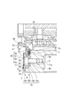
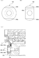
- FIG. 1 It is sectional drawing which shows the structure of the mechanical seal in Example 1 of this invention. It is an expanded sectional view which shows the fixation structure of the adapter by the holder in Example 1.
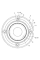
- FIG. It is the top view seen from the machine inner side which shows the fixation structure of the adapter by the holder in Example 1.
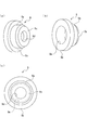
- FIG. (A) And (b) is a perspective view which shows the structure of the holder in Example 1
- (c) is a bottom view similarly. It is a figure which shows the attachment procedure of the adapter by the holder in Example 1.
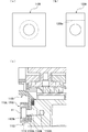
- FIG. (A) And (b) is a bottom view which shows the structure of the holder of the modifications A and B in Example 1
- (c) is an expanded cross section which shows the fixation structure of the adapter by the holder of the modifications A and B FIG.
- (A) And (b) is a bottom view which shows the structure of the holder of modification C, D in Example 1
- (c) is an expanded cross section which shows the fixation structure of the adapter by the holder of the modifications E and F
- FIG. (A) And (b) is a bottom view which shows the structure of the holder of modification G, H in Example 1
- (c) is an expanded section which shows the fixation structure of the adapter by the holder of modification G, H FIG.
- the mechanical seal 1 of this embodiment is provided between a rotary shaft 2 and a seal cover 3 of a rotary machine such as a pump or a compressor, and is connected to the rotary shaft 2 via a sleeve 4.
- An annular rotary seal ring 20, 21 to be fixed, and an annular fixed seal ring 30, 31 fixed to the seal cover 3 and the adapter 5, are constituted by metal bellows members 60, 61.
- the fixed sealing rings 30 and 31 are urged in the axial direction, so that the sliding surfaces 20a and 21a of the rotary sealing rings 20 and 21 and the sliding surfaces 30a and 31a of the fixed sealing rings 30 and 31 are in close contact with each other. It can be moved to seal the sealed fluid in the machine.
- the mechanical seal 1 of the present embodiment is configured as a so-called double-type mechanical seal in which the rotary seal ring 20 and fixed seal ring 30 on the atmosphere side, and the rotary seal ring 21 and fixed seal ring 31 on the inside of the machine face in opposite directions. ing.
- the rotary seal rings 20 and 21 and the fixed seal rings 30 and 31 are typically formed of SiC (hard material) or a combination of SiC (hard material) and carbon (soft material). Any sliding material can be used as long as it is used as a sliding material for a mechanical seal.
- SiC the material which consists of two or more types of phases from which a component and a composition differ, including the sintered compact which used boron, aluminum, carbon, etc. as a sintering auxiliary agent, for example, SiC, SiC with which the graphite particle was disperse
- the carbon resin-molded carbon, sintered carbon, etc. can be used as well as carbon mixed with carbonaceous and graphite.
- a metal material, a resin material, a surface modifying material (coating material), a composite material, and the like are also applicable.
- the seal cover 3 is made of stainless steel, is formed in a substantially cylindrical shape, and a through hole 3b through which the rotary shaft 2 and the sleeve 4 can be inserted is formed inside the cylindrical portion 3a.
- a first annular mounting portion 3g having one end of the bellows member 60 fixed to the atmosphere side, and a cylindrical baffle with a flange on the inner side and the outer diameter side of the first annular mounting portion 3g.
- a second annular attachment portion 3h to which 8 is attached is formed, and the inside of the seal cover 3 is configured in a stepped shape.
- an end surface portion 3c on the inner side of the cylindrical portion 3a is provided with an annular recess 3d recessed toward the atmosphere around the through hole 3b, and extends in the radial direction of the annular recess 3d.
- An annular groove 3e into which an annular squeeze packing 7 is inserted is provided on the inner diameter side of the bottom surface.
- the squeeze packing 7 may be made of an elastic body, and the material may be rubber, resin, graphite, or the like.
- a female screw hole 3f as a screw hole extending in the axial direction toward the atmosphere side is provided on the outer diameter side of the bottom surface extending in the radial direction of the annular recess 3d, that is, on the outer diameter side of the annular groove 3e. .
- the body 11a of the bolt 11 for fixing the adapter 5 to the seal cover 3 is screwed into the female screw hole 3f.
- the housing recess 10 includes an annular bottom surface portion 10a that extends from the opening end portion of the female screw hole 3f, that is, the inner end portion of the female screw hole, perpendicularly to the outer diameter direction, and an inner end extending from the outer diameter side end portion of the bottom surface portion 10a to the inner side.
- a stepped cylindrical space is formed.
- the inner diameter side of the inboard end of the first side surface portion 10b, that is, the through-hole 3b side is connected to the bottom surface extending in the radial direction of the annular recess 3d in the inner diameter direction.
- the accommodating recesses 10 are equally arranged in the circumferential direction of the seal cover 3 together with the female screw holes 3f (see particularly FIG. 3).
- the adapter 5 is made of stainless steel, is formed in a cylindrical shape with a flange, and includes a cylindrical portion 5 a and an annular flange portion 5 b that extends in the outer diameter direction at the atmospheric end of the cylindrical portion 5 a.
- the through-hole 5c which is comprised and can penetrate the rotating shaft 2 is formed inside the cylindrical part 5a.
- an annular mounting portion 5 k is formed on the inside of the machine, to which one end of the bellows member 61 is fixed.
- the adapter 5 is provided with an attachment portion 5 d having a diameter larger than that of the cylindrical portion 5 a at the atmospheric end of the adapter 5, and the outer peripheral dimension of the attachment portion 5 d is the through hole of the seal cover 3.
- the opening end portion of 3b, that is, the inner peripheral size at the inner end portion of the machine is substantially the same.
- the outer diameter portion of the flange portion 5b includes a first outer peripheral surface 5e on the atmosphere side, an annular surface portion 5f on the inner side of the first outer peripheral surface 5e extending in an inner diameter direction from the inner end portion of the first outer peripheral surface 5e and orthogonally connected, and an annular shape
- An annular step portion 5h is formed from the second outer peripheral surface 5g extending from the inner diameter side end of the surface portion 5f to the inside of the machine.
- the atmosphere of the flange portion 5b of the adapter 5 with respect to the bottom surface extending in the radial direction of the annular recess 3d of the seal cover 3 The annular surface portion 5m on the side is in contact with the axial direction.
- the annular step portion 5 h formed on the outer diameter portion of the flange portion 5 b of the adapter 5, that is, the first outer peripheral surface 5 e is continuous with the first side surface portion 10 b of the housing recess 10 of the seal cover 3 in the axial direction. It is configured.
- the machine-side annular surface part 5f constituting the annular step part 5h of the adapter 5 is located in the machine direction in the axial direction by a gap ⁇ relative to the outer edge face part 10c on the outer diameter side constituting the accommodating recess 10 of the seal cover 3. It is formed as follows.
- the holder 9 is made of stainless steel, is formed in a cylindrical shape with a flange, and has a cylindrical portion 9a and an annular outer portion extending in the outer diameter direction at the inner end of the cylindrical portion 9a.
- the holder 9 is inserted into the receiving recess 10 of the seal cover 3 so that the body portion 11a of the bolt 11 is inserted into the through hole 9d and the bolt 11 is held.
- the body 11a of the bolt 11 can be screwed to 3f.
- the holder 9 is formed with an accommodation recess 9e from the cylindrical portion 9a and the machine-side end surface of the bottom 9c, and the head 11b of the bolt 11 can be accommodated in the accommodation recess 9e.
- the diameter of the head 11b of the bolt 11 is configured to be larger than the diameter of the trunk portion 11a
- the diameter of the housing recess 9e is configured to be larger than the diameter of the through hole 9d. Therefore, the bottom portion of the head portion 11b of the bolt 11 housed in the housing recess 9e is obtained by screwing the body portion 11a of the bolt 11 into the female screw hole 3f of the seal cover 3 with the bolt 11 held by the holder 9.
- the end face on the atmosphere side can be pressed against the end face of the bottom portion 9c of the holder 9 in the axial direction.
- the accommodation recessed part 9e of the holder 9 is formed as a cylindrical space, not only this but the shape may be freely formed if it can accommodate the head 11b of the volt
- the flange portion 9b of the holder 9 protrudes to a position where the inner diameter side, that is, the through hole 3b side overlaps the annular step portion 5h of the adapter 5 in the axial direction, the flange portion 9b of the holder 9 and the seal cover 3
- the annular step 5h of the flange portion 5b of the adapter 5 can be sandwiched in the axial direction with the bottom surface extending in the radial direction of the annular recess 3d.
- the squeeze packing 7 disposed between the bottom of the annular recess 3 d of the seal cover 3, that is, between the annular groove 3 e and the flange 5 b of the adapter 5 is compressed in the screwing direction of the bolt 11.
- the assembly procedure of the mechanical seal 1 will be described.
- the bellows member 60 and the fixed sealing ring 30 are fixed to the first annular mounting portion 3 g of the seal cover 3, and the bellows member 61 and the fixed sealing ring 31 are fixed to the annular mounting portion 5 k of the adapter 5.
- the sleeve 4 is inserted into the through hole 3b of the seal cover 3 from the inside of the machine, and the sliding surface 20a of the rotary sealing ring 20 fixed to the holding portion 4a of the sleeve 4 is changed to the sliding surface 30a of the fixed sealing ring 30.
- a squeeze packing 7 coated with a thin molybdenum disulfide grease is inserted into the annular groove 3 e of the seal cover 3.
- the baffle 8 is inserted into the gap between the seal cover 3 and the sleeve 4 from the inside of the machine.
- the relative rotation of the baffle 8 relative to the seal cover 3 is achieved by fitting the locking pin 3m provided in the second annular mounting portion 3h of the seal cover 3 into the notch 8b provided in the flange portion 8a of the baffle 8. Is regulated.
- the mounting portion 5 d of the adapter 5 is inserted into the through hole 3 b of the seal cover 3, and the sliding surface 31 a of the fixed sealing ring 31 fixed to the adapter 5 is fixed to the holding portion 4 a of the sleeve 4.
- the ring 21 is brought into contact with the sliding surface 21a.
- the relative rotation of the adapter 5 with respect to the seal cover 3 is restricted by fitting the locking pin 5n provided in the mounting portion 5d of the adapter 5 into the notch portion 8c provided in the inner end portion of the baffle 8.
- the holder 9 is inserted into the housing recess 10 of the seal cover 3 and the annular step portion 5 h of the adapter 5, and the body portion 11 a of the bolt 11 is inserted into the through hole 9 d of the holder 9.
- the adapter 5 is fixed to the seal cover 3 by screwing the body portion 11a of the bolt 11 into the female screw hole 3f of the seal cover 3 in a state where the seal cover 3 is held.
- a set ring 12 is externally fitted to the atmosphere side end of the sleeve 4 exposed from the through hole 3b of the seal cover 3. After the mechanical seal 1 is assembled, as shown in FIG.
- the mechanical seal 1 is attached to the rotary shaft 2 by inserting the rotary shaft 2 through the screw shaft and evenly fastening the rotary shaft 2 at a plurality of locations in the circumferential direction with the set screw 13.
- the adapter 5 is fixed to the seal cover 3 by the bolts 11 penetrating the through holes 9d of the plurality of holders 9, so that the rotation of the adapter 5 relative to the seal cover 3 is performed.
- the holder 9 receives the rotational force even when a rotational force is applied to the adapter 5, the rotational force is not easily transmitted to the bolt 11, and the bolt 11 can be prevented from loosening.
- the holder 9 is formed with a bottom portion 9c around the through-hole 9d with which an end face on the atmosphere side as a bottom portion of the head portion 11b of the bolt 11 abuts, the head portion 11b of the bolt 11 and the receiving recess of the seal cover 3 Since the holder 9 is pressed against and fixed to the seal cover 3 with the bottom portion 9c of the holder 9 being sandwiched between the bottom surface portion 10a of the holder 10, the holder 9 can be firmly fixed to the seal cover 3. .
- the adapter 5 since the flange portion 5b of the adapter 5 is pressed against and fixed to the annular recess 3d of the seal cover 3 by the inner diameter side of the flange portion 9b of the holder 9, that is, the through hole 3b side, the adapter 5 is firmly attached to the seal cover 3. Can be fixed. Further, if the bolt 11 is tightened until the bottom portion 9c of the holder 9 comes into contact with the bottom surface portion 10a of the housing recess 10 of the seal cover 3, the flange portion 9b of the holder 9 with respect to the annular surface portion 5f of the flange portion 5b of the adapter 5 inside the machine. Since this position becomes the predetermined tightening position, the positioning accuracy in the axial direction is good and the assembly is easy.
- the flange portion 5b of the adapter 5 is sandwiched between the inner diameter side of the flange portion 9b of the holder 9 and the bottom surface extending in the radial direction of the annular recess 3d of the seal cover 3, while the outer diameter of the flange portion 9b of the holder 9 is Since an axial gap ⁇ (see FIG. 2) is formed between the side and the outer edge surface portion 10c of the housing recess 10 of the seal cover 3, the holder 9 is attached to the seal cover 3 when the bolt 11 is tightened. Accordingly, the pressing force for pressing the flange portion 5 b of the adapter 5 between the seal cover 3 and the seal cover 3 can be concentrated on the inner diameter side of the flange portion 9 b of the holder 9.
- the outer diameter side of the flange portion 9b of the holder 9 and the outer edge surface portion 10c of the housing recess 10 of the seal cover 3 may be in contact with each other in the axial direction, that is, the gap ⁇ may not be provided.
- the squeeze packing 7 is disposed between the inner diameter side of the flange portion 9b of the holder 9 in the screwing direction of the bolt 11 and the bottom portion of the annular recess 3d of the seal cover 3, the bolt 11 is tightened.
- the squeeze packing 7 is compressed in the screwing direction of the bolt 11 by the flange portion 5b of the adapter 5 that receives the pressing force of the holder 9, and the sealing performance is high. From this, it becomes possible to constitute a mechanical seal that seals the shaft of a high-pressure sealed fluid using the metal bellows members 60 and 61.
- the squeeze packing 7 is interposed between the adapter 5 and the seal cover 3, friction between the adapter 5 and the seal cover 3 increases, so that the relative rotation of the adapter 5 with respect to the seal cover 3 is suppressed. Can do.
- the holder 9 is provided with an accommodation recess 9e for accommodating the head portion 11b of the bolt 11, the head portion 11b of the bolt 11 does not protrude outward from the holder 9, that is, the inside of the machine, thus saving space. can do.
- the accommodation recessed part 9e of the holder 9 may be comprised so that the head 11b of the volt
- the seal cover 3 is provided with the housing recess 10 for housing the holder 9, the holder 9 does not protrude outward from the end surface portion 3 c on the machine inner side of the seal cover 3, and space can be saved. it can.
- the housing recess 10 of the seal cover 3 may be configured such that a part of the holder 9 slightly protrudes outside the end surface portion 3c on the machine inner side of the seal cover 3, that is, on the machine inner side.
- the holder 9 is formed in a circular shape as viewed in the screwing direction, and the receiving recess 10 of the seal cover 3 is formed in a substantially circular shape as viewed in the screwing direction, and the holder 9 is inserted into the receiving recess 10 of the seal cover 3.
- the holder 9 can rotate relative to the seal cover 3 and the adapter 5, the holder 9 is easily rotated by receiving the rotational force even if a rotational force is applied to the adapter 5, and the rotational force is applied to the bolt 11. Is more difficult to transmit, and the bolt 11 can be prevented from loosening.
- the holder 9 may be configured in a polygonal shape as viewed in the screwing direction, for example, as long as the holder 9 can be rotated in a state of being inserted into the housing recess 10 of the seal cover 3. Further, the holder 9 can be easily assembled / assembled with respect to the accommodating recess 10 of the seal cover 3.
- the holders 9 are located between the holders 9 as compared with the conventional annular thin plate along the circumferential direction of the seal cover 3. Space can be secured in the circumferential direction, and heat transfer from the inside of the machine can be suppressed. Moreover, since the seal cover 3, the adapter 5, and the holder 9 are made of the same stainless steel, stress is relatively difficult to act due to thermal expansion.
- a modified example of the holder 9 in the first embodiment will be described.
- a holder 109 shown in FIG. 6A is formed in a circular shape as viewed in the screwing direction without a flange portion extending in the outer diameter direction.
- the seal cover 103 has an annular recess 103b formed to the outer diameter side.
- the adapter 105 has a flange portion 105 b extending to the outer diameter portion of the annular recess 103 b of the seal cover 103, and an accommodation recess 110 is formed by the flange portion 105 b of the adapter 105 and the annular recess 103 b of the seal cover 103.
- a through hole 105k that penetrates in the axial direction is formed in the flange portion 105b of the adapter 105 at a position corresponding to the female screw hole 103h of the seal cover 103 (see FIG. 6C).
- a holder 209 shown in FIG. 6B is formed in a stadium shape as viewed in the screwing direction without a flange portion extending in the outer diameter direction.
- the holder 209 is notched at the end in the direction orthogonal to the radial direction of the seal cover 103, and the housing recess 209 e is formed in a rectangular parallelepiped shape that opens in a direction orthogonal to the radial direction of the seal cover 103.
- the seal cover and the adapter to which the holder 209 of the modified example B is applied have the same configuration as the seal cover 103 and the adapter 105 described above, and thus description thereof is omitted.
- the “notch” means that it is not necessary to be actually cut and manufactured, and any shape having a notch may be used. The same applies to the following.
- the holders 109 and 209 of the modified examples A and B are formed in a circular shape as viewed in the screwing direction or a stadium shape as viewed in the screwing direction, and the holders 109 and 209 can rotate relative to the seal cover 103 and the adapter 105. Therefore, even if a rotational force is applied to the adapter 105, the holders 109 and 209 are easily rotated by receiving the rotational force, and the rotational force is less easily transmitted to the bolt 11, and the bolt 11 can be prevented from loosening. Further, the assembly / assembly of the holder 9 with respect to the housing recess 110 of the seal cover 103 can be easily performed.
- a holder 309 shown in FIG. 7A is formed in a circular shape when viewed in the screwing direction and substantially corresponds to the inner diameter side and the outer diameter side of the seal cover 303.
- a semicircular flange portion 309b is formed.
- the accommodation recess 310 of the seal cover 303 is formed in a circular shape in the screwing direction in accordance with the shape of the holder 309 (see FIG. 7C).
- a holder 409 shown in FIG. 7B is formed in a stadium shape as viewed in the screwing direction, and corresponds to the inner diameter side and the outer diameter side of the seal cover 303.
- a substantially semi-circular flange portion 409b is formed.
- the holder 409 is notched at the end in the direction orthogonal to the flange portion 409b, and the housing recess 409e is formed in a rectangular parallelepiped shape that opens in the direction orthogonal to the flange portion 409b.
- the seal cover to which the holder 409 of Modification D is applied has the same configuration as the seal cover 303 described above, description thereof is omitted.
- a holder 509 shown in FIG. 8A is formed in a circular shape in the screwing direction, and a flange portion 509 b is formed corresponding to the inner diameter side of the seal cover 503.
- the accommodation recess 510 of the seal cover 503 is formed in a circular shape in the screwing direction in accordance with the shape of the holder 509 (see FIG. 8C).
- a holder 609 shown in FIG. 8B is formed in a stadium shape as viewed in the screwing direction, and corresponds to the inner diameter side and the outer diameter side of the seal cover 503.
- a substantially semicircular flange portion 609b is formed.
- the holder 609 is cut out at the end in the direction orthogonal to the flange portion 609b, and the receiving recess 609e is formed in a rectangular parallelepiped shape that opens in the direction orthogonal to the flange portion 609b.
- the seal cover to which the holder 609 of the modified example F is applied has the same configuration as the seal cover 503 described above, description thereof is omitted.
- the shape of the holders 309, 409, 509, 609 and the receiving recesses 310, 510 of the seal covers 303, 503 are formed in a circular shape as viewed in the screwing direction or a stadium shape as viewed in the screwing direction, and fitted. Therefore, the holders 309, 409, 509, and 609 are inserted into the recesses 310 and 510 of the seal covers 303 and 503, and the holders 309, 409, 509, and 609 are applied even when a rotational force is applied to the adapter 5. Therefore, the rotational force is not transmitted to the bolt 11, and the bolt 11 can be prevented from loosening more reliably. Further, the holders 309, 409, 509, and 609 can be easily assembled / assembled with respect to the housing recesses 310 and 510 of the seal covers 303 and 503.
- a holder 709 shown in FIG. 9A is formed in a square shape in the screwing direction, and has flanges corresponding to the inner diameter side and the outer diameter side of the seal cover 703. Each portion 709b is formed.
- the accommodation recess 710 of the seal cover 703 is formed in a square shape in the screwing direction in accordance with the shape of the holder 709 (see FIG. 9C).
- a holder 809 shown in FIG. 9B is formed in a rectangular shape in the screwing direction and has flanges corresponding to the inner diameter side and the outer diameter side of the seal cover 703. Each portion 809b is formed.
- the accommodation recessed part 809e of the holder 809 is formed in the rectangular parallelepiped shape open
- the seal cover to which the holder 809 of the modified example H is applied has the same configuration as the seal cover 703 described above, and thus the description thereof is omitted.
- a holder 909 shown in FIG. 10A is formed in a square shape in the screwing direction, and a flange portion 909b is formed corresponding to the inner diameter side of the seal cover 903.
- the accommodation recess 910 of the seal cover 903 is formed in a square shape in the screwing direction according to the shape of the holder 909 (see FIG. 10C).
- a holder 1009 shown in FIG. 10B is formed in a rectangular shape in the screwing direction, and a flange portion 1009b is formed corresponding to the inner diameter side of the seal cover 903.
- the accommodation recessed part 1009e of the holder 1009 is formed in the rectangular parallelepiped shape open
- the seal cover to which the holder 1009 of Modification J is applied has the same configuration as the above-described seal cover 903, and thus description thereof is omitted.
- a holder 1109 shown in FIG. 11A is formed in a square in a screwing direction view without a flange portion extending in the outer diameter direction.
- the seal cover 1103 has an annular recess 1103b formed to the outer diameter side.
- the adapter 1105 has a flange portion 1105 b extending to the outer diameter portion of the annular recess 1103 b of the seal cover 1103, and an accommodation recess 1110 is formed by the flange portion 1105 b of the adapter 105 and the annular recess 1103 b of the seal cover 1103. Yes.
- a through hole 1105k that penetrates in the axial direction is formed in the flange portion 1105b of the adapter 1105 at a position corresponding to the female screw hole 1103h of the seal cover 1103 (see FIG. 11C).
- a holder 1209 shown in FIG. 11B is formed in a rectangular shape in the screwing direction as viewed without a flange portion extending in the outer diameter direction.
- the accommodation recessed part 1209e of the holder 1209 is formed in the rectangular parallelepiped shape open
- the seal cover and the adapter to which the holder 1209 of the modified example M is applied have the same configuration as the seal cover 1103 and the adapter 1105 described above, and thus the description thereof is omitted.
- the holders 709, 809, 909, 1009, 1109, 1209 and the receiving recesses 710, 910, 1110 of the seal covers 703, 903, 1103 are formed in a non-circular shape when viewed in the screwing direction, and are fitted Therefore, a rotational force is applied to the adapters 5 and 1105 in a state where the holders 709, 809, 909, 1009, 1109 and 1209 are fitted in the receiving recesses 710, 910 and 1110 of the seal covers 703, 903 and 1103.
- the rotational force of the holders 709, 809, 909, 1009, 1109, 1209 is restricted, the rotational force is not transmitted to the bolt 11, and the loosening of the bolt 11 can be prevented more reliably.
- the rectangular thing was demonstrated as a shape of the accommodation recessed part of the holder and seal cover which are formed in a non-circular view in the screwing direction, it is not limited to this, and is formed as a polygon such as a hexagon or an octagon. Also good.
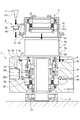
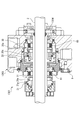
- the mechanical seal 1301 in Example 2 will be described. As shown in FIG. 12, in this embodiment, the mechanical seal 1301 is provided between the rotary shaft 2 of the rotary machine such as a pump or a compressor and the seal cover 1303, and the rotary shaft 2 is interposed via the sleeve 1304.
- the ring-shaped rotary seal rings 20 and 21 fixed to the ring and the ring-shaped fixed seal rings 30 and 31 fixed to the seal cover 1303 and the adapter 1305 are mainly composed of metal bellows members 60 and 61.
- the fixed sealing rings 30 and 31 are urged in the axial direction by the above, so that the sliding surfaces 20a and 21a of the rotary sealing rings 20 and 21 and the sliding surfaces 30a and 31a of the fixed sealing rings 30 and 31 are brought into close contact with each other. It can be slid to seal the sealed fluid.
- the mechanical seal 1301 of the present embodiment is configured as a so-called tandem mechanical seal in which the rotary seal ring 20 and fixed seal ring 30 on the atmosphere side, and the rotary seal ring 21 and fixed seal ring 31 on the inside of the machine face the same direction. ing.
- the holder 9 described in the first embodiment is used for fixing the adapter 1305 to the seal cover 1303 by the holder.
- the holder 9 is not limited to this, and the holder 9 of the first embodiment described above is used.
- the configurations of the modified examples A to M may be applied. It goes without saying that the shapes of the seal cover and the adapter are also changed in accordance with the configuration of the applied holder.
- the holder has been described as being inserted into the housing recess formed in the seal cover or the housing recess formed by the flange portion of the seal cover and the adapter. There is no need to provide an accommodation recess in the flange portion.
- the holders are not limited to four, and a plurality of holders may be arranged in the circumferential direction.
- the adapter may be fixed to the seal cover from the atmosphere side.
- adapter fixing structure using the holder described in the above embodiment may be applied to a single-type mechanical seal.
Landscapes
- Engineering & Computer Science (AREA)
- General Engineering & Computer Science (AREA)
- Mechanical Engineering (AREA)
- Mechanical Sealing (AREA)
Abstract
L'invention concerne un joint mécanique dans lequel une force de rotation a peu de chance d'être transmise à un boulon et dans lequel le desserrage du boulon peut être empêché. Le joint mécanique (1) selon l'invention comprend : des bagues d'étanchéité rotatives (20, 21) qui tournent avec un arbre rotatif (2) ; des bagues d'étanchéité fixes (30, 31) ; et un adaptateur (5) qui maintient les bagues d'étanchéité fixes (30, 31), l'adaptateur (5) étant fixé à un couvercle d'étanchéité (3) par des boulons (11). Le joint mécanique (1) est en outre pourvu d'une pluralité de supports (9) qui sont en contact axial avec l'adaptateur (5) et qui sont pourvus de trous traversants (9d) dans lesquels sont insérés les corps (11a) des boulons (11), en prise avec des trous filetés (3f) dans le couvercle d'étanchéité (3). La pluralité de supports (9) sont agencés pour entourer l'arbre rotatif (2).
Priority Applications (5)
| Application Number | Priority Date | Filing Date | Title |
|---|---|---|---|
| JP2020512247A JP7201666B2 (ja) | 2018-04-03 | 2019-04-02 | メカニカルシール |
| EP19780777.9A EP3779247B1 (fr) | 2018-04-03 | 2019-04-02 | Joint mécanique |
| CN201980019474.1A CN111868423B (zh) | 2018-04-03 | 2019-04-02 | 机械密封 |
| US16/982,026 US11802623B2 (en) | 2018-04-03 | 2019-04-02 | Mechanical seal |
| US18/071,397 US11815183B2 (en) | 2018-04-03 | 2022-11-29 | Mechanical seal |
Applications Claiming Priority (2)
| Application Number | Priority Date | Filing Date | Title |
|---|---|---|---|
| JP2018-071502 | 2018-04-03 | ||
| JP2018071502 | 2018-04-03 |
Related Child Applications (2)
| Application Number | Title | Priority Date | Filing Date |
|---|---|---|---|
| US16/982,026 A-371-Of-International US11802623B2 (en) | 2018-04-03 | 2019-04-02 | Mechanical seal |
| US18/071,397 Division US11815183B2 (en) | 2018-04-03 | 2022-11-29 | Mechanical seal |
Publications (1)
| Publication Number | Publication Date |
|---|---|
| WO2019194154A1 true WO2019194154A1 (fr) | 2019-10-10 |
Family
ID=68100561
Family Applications (1)
| Application Number | Title | Priority Date | Filing Date |
|---|---|---|---|
| PCT/JP2019/014573 WO2019194154A1 (fr) | 2018-04-03 | 2019-04-02 | Joint mécanique |
Country Status (5)
| Country | Link |
|---|---|
| US (2) | US11802623B2 (fr) |
| EP (1) | EP3779247B1 (fr) |
| JP (1) | JP7201666B2 (fr) |
| CN (1) | CN111868423B (fr) |
| WO (1) | WO2019194154A1 (fr) |
Citations (5)
| Publication number | Priority date | Publication date | Assignee | Title |
|---|---|---|---|---|
| JP2006519348A (ja) * | 2003-02-28 | 2006-08-24 | エイ・ダブリュー・チェスタトン・カンパニー | メカニカルシール用自動係脱式スペーシング機構 |
| JP4684421B2 (ja) | 1999-03-22 | 2011-05-18 | ドレッサー、ランド、ソシエテ、アノニム | シャフトシール |
| WO2014034582A1 (fr) * | 2012-08-29 | 2014-03-06 | イーグル工業株式会社 | Garniture mécanique |
| JP2017025994A (ja) * | 2015-07-21 | 2017-02-02 | 株式会社デンソー | 締結装置 |
| JP6196727B2 (ja) | 2013-04-24 | 2017-09-13 | イーグルブルクマン ジャーマニー ゲセルシャフト ミト ベシュレンクテル ハフツング ウント コンパニー コマンディトゲゼルシャフト | 簡易な構造のメカニカルシール |
Family Cites Families (14)
| Publication number | Priority date | Publication date | Assignee | Title |
|---|---|---|---|---|
| US2949143A (en) * | 1956-10-12 | 1960-08-16 | Waldes Kohinoor Inc | Fastening means for panels, sheets and the like |
| US3062253A (en) * | 1958-08-26 | 1962-11-06 | Waldes Kohinoor Inc | Bolt and shear sleeve with shear sleeve retracting means |
| US3218906A (en) * | 1962-06-18 | 1965-11-23 | James N Dupree | Captive screw and washer assembly |
| US3743302A (en) * | 1971-12-29 | 1973-07-03 | Klein Schanzlin & Becker Ag | Sealing arrangement |
| JPS6196727U (fr) | 1984-11-28 | 1986-06-21 | ||
| CN101131210A (zh) | 2006-09-18 | 2008-02-27 | 丹东克隆集团有限责任公司 | 集装式磁力轴密封装置 |
| CN101021270A (zh) | 2007-03-29 | 2007-08-22 | 合肥华升泵阀有限责任公司 | 用于高黏度介质的机械密封装置 |
| CN101158361A (zh) | 2007-09-28 | 2008-04-09 | 贵州宏福实业开发有限总公司 | 磷酸轴流泵干气密封装置 |
| CN101457841B (zh) | 2007-12-13 | 2010-08-25 | 丹东克隆集团有限责任公司 | 波纹管机械密封装置 |
| DE102009018279A1 (de) | 2009-04-21 | 2009-11-19 | Daimler Ag | Schraubverbindung |
| CN104395654B (zh) | 2012-09-11 | 2016-02-17 | 伊格尔工业股份有限公司 | 机械密封 |
| CN103291930A (zh) | 2013-06-27 | 2013-09-11 | 无锡市宏源弹性器材有限公司 | 迷宫式隔水密封装置 |
| US10352454B2 (en) | 2014-11-04 | 2019-07-16 | Eagle Industry Co., Ltd. | Mechanical seal device |
| CN205479358U (zh) | 2016-02-15 | 2016-08-17 | 宜兴市鑫鹏非金属化工设备有限公司 | 一种机械密封用工夹具 |
-
2019
- 2019-04-02 US US16/982,026 patent/US11802623B2/en active Active
- 2019-04-02 CN CN201980019474.1A patent/CN111868423B/zh active Active
- 2019-04-02 WO PCT/JP2019/014573 patent/WO2019194154A1/fr unknown
- 2019-04-02 JP JP2020512247A patent/JP7201666B2/ja active Active
- 2019-04-02 EP EP19780777.9A patent/EP3779247B1/fr active Active
-
2022
- 2022-11-29 US US18/071,397 patent/US11815183B2/en active Active
Patent Citations (5)
| Publication number | Priority date | Publication date | Assignee | Title |
|---|---|---|---|---|
| JP4684421B2 (ja) | 1999-03-22 | 2011-05-18 | ドレッサー、ランド、ソシエテ、アノニム | シャフトシール |
| JP2006519348A (ja) * | 2003-02-28 | 2006-08-24 | エイ・ダブリュー・チェスタトン・カンパニー | メカニカルシール用自動係脱式スペーシング機構 |
| WO2014034582A1 (fr) * | 2012-08-29 | 2014-03-06 | イーグル工業株式会社 | Garniture mécanique |
| JP6196727B2 (ja) | 2013-04-24 | 2017-09-13 | イーグルブルクマン ジャーマニー ゲセルシャフト ミト ベシュレンクテル ハフツング ウント コンパニー コマンディトゲゼルシャフト | 簡易な構造のメカニカルシール |
| JP2017025994A (ja) * | 2015-07-21 | 2017-02-02 | 株式会社デンソー | 締結装置 |
Also Published As
| Publication number | Publication date |
|---|---|
| JPWO2019194154A1 (ja) | 2021-04-08 |
| US20230109060A1 (en) | 2023-04-06 |
| EP3779247A4 (fr) | 2021-12-29 |
| EP3779247B1 (fr) | 2023-09-13 |
| US20210018100A1 (en) | 2021-01-21 |
| EP3779247A1 (fr) | 2021-02-17 |
| US11815183B2 (en) | 2023-11-14 |
| JP7201666B2 (ja) | 2023-01-10 |
| CN111868423A (zh) | 2020-10-30 |
| CN111868423B (zh) | 2022-08-09 |
| US11802623B2 (en) | 2023-10-31 |
Similar Documents
| Publication | Publication Date | Title |
|---|---|---|
| US9243645B2 (en) | Fixture used in rotary machine and method for transporting rotary machine | |
| US4256313A (en) | Universal mechanical seal gland | |
| US5662340A (en) | Fully split cartridge mechanical seal assembly | |
| US4332391A (en) | Universal mechanical seal gland | |
| JPS62270870A (ja) | シ−ル装置 | |
| WO2019194154A1 (fr) | Joint mécanique | |
| US5538257A (en) | Spring device and method for holding a component on a shaft and pusher seal assembly using same | |
| WO2018012330A1 (fr) | Joint mécanique | |
| GB2087514A (en) | A coupling device | |
| US6017036A (en) | Mechanical shaft seal | |
| JP6991943B2 (ja) | 分割型メカニカルシール | |
| JP5839716B2 (ja) | メカニカルシール | |
| JP2023528275A (ja) | メカニカルシールのための一点操作薄型ロックリング | |
| JP7372831B2 (ja) | メカニカルシール | |
| JP7154714B2 (ja) | メカニカルシール | |
| JPH0596552U (ja) | 止め輪を具えた軸と回転体の締結装置 | |
| JP7234073B2 (ja) | ダブル型メカニカルシール | |
| JP7249252B2 (ja) | 軸封装置 | |
| US20200063800A1 (en) | Fixing apparatus for fixing a shaft to a mounting part and actuator of a robot | |
| CN110268184B (zh) | 旋转引入装置和曲轴组件 | |
| JP4076626B2 (ja) | メカニカルシール | |
| JP2024033685A (ja) | メカニカルシール | |
| KR20200024528A (ko) | 베어링 지지 구조 | |
| JP2002089719A (ja) | セグメントシール |
Legal Events
| Date | Code | Title | Description |
|---|---|---|---|
| 121 | Ep: the epo has been informed by wipo that ep was designated in this application |
Ref document number: 19780777 Country of ref document: EP Kind code of ref document: A1 |
|
| ENP | Entry into the national phase |
Ref document number: 2020512247 Country of ref document: JP Kind code of ref document: A |
|
| NENP | Non-entry into the national phase |
Ref country code: DE |
|
| ENP | Entry into the national phase |
Ref document number: 2019780777 Country of ref document: EP Effective date: 20201103 |