WO2019194154A1 - Mechanical seal - Google Patents
Mechanical seal Download PDFInfo
- Publication number
- WO2019194154A1 WO2019194154A1 PCT/JP2019/014573 JP2019014573W WO2019194154A1 WO 2019194154 A1 WO2019194154 A1 WO 2019194154A1 JP 2019014573 W JP2019014573 W JP 2019014573W WO 2019194154 A1 WO2019194154 A1 WO 2019194154A1
- Authority
- WO
- WIPO (PCT)
- Prior art keywords
- holder
- seal cover
- adapter
- seal
- bolt
- Prior art date
Links
- 238000012856 packing Methods 0.000 claims description 11
- 238000007789 sealing Methods 0.000 abstract description 22
- 238000012986 modification Methods 0.000 description 18
- 230000004048 modification Effects 0.000 description 18
- 230000004308 accommodation Effects 0.000 description 16
- 239000000463 material Substances 0.000 description 10
- OKTJSMMVPCPJKN-UHFFFAOYSA-N Carbon Chemical compound [C] OKTJSMMVPCPJKN-UHFFFAOYSA-N 0.000 description 9
- 230000002093 peripheral effect Effects 0.000 description 9
- 229910052799 carbon Inorganic materials 0.000 description 6
- 239000012530 fluid Substances 0.000 description 4
- 229910001220 stainless steel Inorganic materials 0.000 description 4
- 239000010935 stainless steel Substances 0.000 description 4
- 229910002804 graphite Inorganic materials 0.000 description 3
- 239000010439 graphite Substances 0.000 description 3
- 229910052751 metal Inorganic materials 0.000 description 3
- 239000002184 metal Substances 0.000 description 3
- 238000000034 method Methods 0.000 description 2
- 230000000149 penetrating effect Effects 0.000 description 2
- 230000001105 regulatory effect Effects 0.000 description 2
- 239000011347 resin Substances 0.000 description 2
- 229920005989 resin Polymers 0.000 description 2
- ZOXJGFHDIHLPTG-UHFFFAOYSA-N Boron Chemical compound [B] ZOXJGFHDIHLPTG-UHFFFAOYSA-N 0.000 description 1
- 229910052782 aluminium Inorganic materials 0.000 description 1
- XAGFODPZIPBFFR-UHFFFAOYSA-N aluminium Chemical compound [Al] XAGFODPZIPBFFR-UHFFFAOYSA-N 0.000 description 1
- 239000012752 auxiliary agent Substances 0.000 description 1
- 229910052796 boron Inorganic materials 0.000 description 1
- 239000011248 coating agent Substances 0.000 description 1
- 238000000576 coating method Methods 0.000 description 1
- 239000002131 composite material Substances 0.000 description 1
- 239000004519 grease Substances 0.000 description 1
- 238000003780 insertion Methods 0.000 description 1
- 230000037431 insertion Effects 0.000 description 1
- 239000007769 metal material Substances 0.000 description 1
- 239000000203 mixture Substances 0.000 description 1
- CWQXQMHSOZUFJS-UHFFFAOYSA-N molybdenum disulfide Chemical compound S=[Mo]=S CWQXQMHSOZUFJS-UHFFFAOYSA-N 0.000 description 1
- 229910052982 molybdenum disulfide Inorganic materials 0.000 description 1
- 239000002245 particle Substances 0.000 description 1
- 239000005060 rubber Substances 0.000 description 1
- 238000005245 sintering Methods 0.000 description 1
- 239000007779 soft material Substances 0.000 description 1
- 238000012546 transfer Methods 0.000 description 1
Images


Classifications
-
- F—MECHANICAL ENGINEERING; LIGHTING; HEATING; WEAPONS; BLASTING
- F16—ENGINEERING ELEMENTS AND UNITS; GENERAL MEASURES FOR PRODUCING AND MAINTAINING EFFECTIVE FUNCTIONING OF MACHINES OR INSTALLATIONS; THERMAL INSULATION IN GENERAL
- F16J—PISTONS; CYLINDERS; SEALINGS
- F16J15/00—Sealings
- F16J15/16—Sealings between relatively-moving surfaces
- F16J15/34—Sealings between relatively-moving surfaces with slip-ring pressed against a more or less radial face on one member
- F16J15/3464—Mounting of the seal
- F16J15/348—Pre-assembled seals, e.g. cartridge seals
- F16J15/3484—Tandem seals
-
- F—MECHANICAL ENGINEERING; LIGHTING; HEATING; WEAPONS; BLASTING
- F16—ENGINEERING ELEMENTS AND UNITS; GENERAL MEASURES FOR PRODUCING AND MAINTAINING EFFECTIVE FUNCTIONING OF MACHINES OR INSTALLATIONS; THERMAL INSULATION IN GENERAL
- F16J—PISTONS; CYLINDERS; SEALINGS
- F16J15/00—Sealings
- F16J15/16—Sealings between relatively-moving surfaces
- F16J15/34—Sealings between relatively-moving surfaces with slip-ring pressed against a more or less radial face on one member
- F16J15/3464—Mounting of the seal
-
- F—MECHANICAL ENGINEERING; LIGHTING; HEATING; WEAPONS; BLASTING
- F16—ENGINEERING ELEMENTS AND UNITS; GENERAL MEASURES FOR PRODUCING AND MAINTAINING EFFECTIVE FUNCTIONING OF MACHINES OR INSTALLATIONS; THERMAL INSULATION IN GENERAL
- F16B—DEVICES FOR FASTENING OR SECURING CONSTRUCTIONAL ELEMENTS OR MACHINE PARTS TOGETHER, e.g. NAILS, BOLTS, CIRCLIPS, CLAMPS, CLIPS OR WEDGES; JOINTS OR JOINTING
- F16B39/00—Locking of screws, bolts or nuts
- F16B39/22—Locking of screws, bolts or nuts in which the locking takes place during screwing down or tightening
- F16B39/24—Locking of screws, bolts or nuts in which the locking takes place during screwing down or tightening by means of washers, spring washers, or resilient plates that lock against the object
-
- F—MECHANICAL ENGINEERING; LIGHTING; HEATING; WEAPONS; BLASTING
- F16—ENGINEERING ELEMENTS AND UNITS; GENERAL MEASURES FOR PRODUCING AND MAINTAINING EFFECTIVE FUNCTIONING OF MACHINES OR INSTALLATIONS; THERMAL INSULATION IN GENERAL
- F16B—DEVICES FOR FASTENING OR SECURING CONSTRUCTIONAL ELEMENTS OR MACHINE PARTS TOGETHER, e.g. NAILS, BOLTS, CIRCLIPS, CLAMPS, CLIPS OR WEDGES; JOINTS OR JOINTING
- F16B43/00—Washers or equivalent devices; Other devices for supporting bolt-heads or nuts
-
- F—MECHANICAL ENGINEERING; LIGHTING; HEATING; WEAPONS; BLASTING
- F16—ENGINEERING ELEMENTS AND UNITS; GENERAL MEASURES FOR PRODUCING AND MAINTAINING EFFECTIVE FUNCTIONING OF MACHINES OR INSTALLATIONS; THERMAL INSULATION IN GENERAL
- F16B—DEVICES FOR FASTENING OR SECURING CONSTRUCTIONAL ELEMENTS OR MACHINE PARTS TOGETHER, e.g. NAILS, BOLTS, CIRCLIPS, CLAMPS, CLIPS OR WEDGES; JOINTS OR JOINTING
- F16B5/00—Joining sheets or plates, e.g. panels, to one another or to strips or bars parallel to them
- F16B5/02—Joining sheets or plates, e.g. panels, to one another or to strips or bars parallel to them by means of fastening members using screw-thread
Definitions
- the present invention relates to a mechanical seal, particularly a mechanical seal in which an adapter is fixed to a seal cover with bolts.
- a mechanical seal provided between a rotary shaft of a rotary machine such as a pump or a compressor and a seal cover urges a fixed seal ring by a biasing means against a rotary seal ring fixed to the rotary shaft, and rotates.
- the fluid to be sealed is shaft-sealed by relatively rotating the sliding surfaces of the sealing ring and the fixed sealing ring in close contact with each other.
- an adapter is used to fix the fixed sealing ring to the seal cover, and the adapter is held by the adapter, and the adapter is inserted into the recess of the seal cover from the axial direction and fixed, thereby simplifying the assembly. ing.
- an annular thin plate is respectively attached to the side end of the adapter and the side end of the seal cover in a state where the adapter having an O-ring attached to the outer periphery is inserted into the recess of the seal cover from the axial direction.
- the bolt with head is inserted into the through hole of the annular thin plate and screwed into the female thread extending in the axial direction of the seal cover to fix the annular thin plate to the seal cover, and the adapter is positioned and fixed in the axial direction. is doing.
- the adapter since only an O-ring is interposed between the inner periphery of the seal cover and the outer periphery of the adapter, the adapter is easy to rotate with respect to the seal cover, and the sealing performance is low.
- Japanese Patent No. 4684421 page 4, FIGS. 1 to 4
- Japanese Patent No. 6196727 page 4, FIG. 2
- the countersunk screw is configured to be in direct contact with the adapter, and when a rotational force from the rotation shaft is applied to the adapter, the adapter rotates relative to the seal cover. Since the rotational force is directly transmitted to the head of the countersunk screw which is in contact, there is a problem that the flat screw is likely to be loosened.
- the present invention has been made paying attention to such problems, and an object of the present invention is to provide a mechanical seal that is difficult to transmit a rotational force to a bolt and that can prevent the bolt from loosening.
- the mechanical seal of the present invention is A mechanical seal comprising a rotary seal ring that rotates together with a rotary shaft, a fixed seal ring, and an adapter that holds the fixed seal ring, wherein the adapter is fixed to a seal cover by a bolt, A holder that is in axial contact with the adapter and includes a through-hole through which the bolt body screwed into the screw hole of the seal cover passes, the holder surrounding the rotating shaft; It is characterized by being arranged in multiple numbers.
- the adapter since the adapter is fixed to the seal cover by the bolts penetrating the respective through holes of the plurality of holders, the rotation of the adapter relative to the seal cover is suppressed, and the holder can be applied even if a rotational force is applied to the adapter. Since it receives the rotational force, it is difficult to transmit the rotational force to the bolt, and the bolt can be prevented from loosening.
- the holder is formed with an inner collar portion around which the bottom portion of the bolt head abuts around the through hole. According to this, since the holder is pressed against and fixed to the seal cover in a state where the inner flange is sandwiched between the head of the bolt and the seal cover, the positioning accuracy in the axial direction of the holder is good, and The holder can be firmly fixed to the seal cover.
- the contact part of the said holder with respect to the said adapter is an outer collar part extended to an outer-diameter side. According to this, the adapter can be firmly fixed to the seal cover because the adapter is pressed against and fixed to the seal cover by the outer flange portion.
- the holder is provided with a housing recess for housing the head of the bolt. According to this, the amount of the head portion of the bolt that projects outward from the holder is small or does not project outward.
- the seal cover is provided with an accommodating recess for accommodating the holder. According to this, the amount of the holder projecting outward from the seal cover is small or does not project outward.
- the holder and the receiving recess of the seal cover are formed in a circular shape as viewed in the screwing direction and are fitted. According to this, the assembly / assembly of the holder with respect to the housing recess of the seal cover can be easily performed.
- the holder and the receiving recess of the seal cover are formed in a non-circular shape in the screwing direction and are fitted. According to this, since the rotational force of the holder is regulated even if a rotational force is applied to the adapter in a state where the holder is fitted in the housing recess, the rotational force is not transmitted to the bolt. It is possible to reliably prevent the bolts from loosening.
- the adapter is sandwiched between the inner diameter side of the outer flange portion and the seal cover, A gap is formed between the outer diameter side of the outer flange portion and the seal cover. According to this, when the bolt is tightened, the pressing force for pinching the adapter with the seal cover can be concentrated on the inner diameter side of the outer flange portion of the holder.
- a squeeze packing is disposed between the holder and the seal cover in the screwing direction of the bolt. According to this, since the squeeze packing is compressed in the screw insertion direction of the bolt by the adapter pressed by the holder, the sealing performance is high.
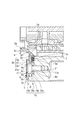
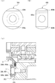
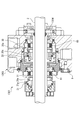
- FIG. 1 It is sectional drawing which shows the structure of the mechanical seal in Example 1 of this invention. It is an expanded sectional view which shows the fixation structure of the adapter by the holder in Example 1.
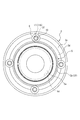
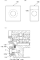
- FIG. It is the top view seen from the machine inner side which shows the fixation structure of the adapter by the holder in Example 1.
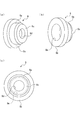
- FIG. (A) And (b) is a perspective view which shows the structure of the holder in Example 1
- (c) is a bottom view similarly. It is a figure which shows the attachment procedure of the adapter by the holder in Example 1.
- FIG. (A) And (b) is a bottom view which shows the structure of the holder of the modifications A and B in Example 1
- (c) is an expanded cross section which shows the fixation structure of the adapter by the holder of the modifications A and B FIG.
- (A) And (b) is a bottom view which shows the structure of the holder of modification C, D in Example 1
- (c) is an expanded cross section which shows the fixation structure of the adapter by the holder of the modifications E and F
- FIG. (A) And (b) is a bottom view which shows the structure of the holder of modification G, H in Example 1
- (c) is an expanded section which shows the fixation structure of the adapter by the holder of modification G, H FIG.
- the mechanical seal 1 of this embodiment is provided between a rotary shaft 2 and a seal cover 3 of a rotary machine such as a pump or a compressor, and is connected to the rotary shaft 2 via a sleeve 4.
- An annular rotary seal ring 20, 21 to be fixed, and an annular fixed seal ring 30, 31 fixed to the seal cover 3 and the adapter 5, are constituted by metal bellows members 60, 61.
- the fixed sealing rings 30 and 31 are urged in the axial direction, so that the sliding surfaces 20a and 21a of the rotary sealing rings 20 and 21 and the sliding surfaces 30a and 31a of the fixed sealing rings 30 and 31 are in close contact with each other. It can be moved to seal the sealed fluid in the machine.
- the mechanical seal 1 of the present embodiment is configured as a so-called double-type mechanical seal in which the rotary seal ring 20 and fixed seal ring 30 on the atmosphere side, and the rotary seal ring 21 and fixed seal ring 31 on the inside of the machine face in opposite directions. ing.
- the rotary seal rings 20 and 21 and the fixed seal rings 30 and 31 are typically formed of SiC (hard material) or a combination of SiC (hard material) and carbon (soft material). Any sliding material can be used as long as it is used as a sliding material for a mechanical seal.
- SiC the material which consists of two or more types of phases from which a component and a composition differ, including the sintered compact which used boron, aluminum, carbon, etc. as a sintering auxiliary agent, for example, SiC, SiC with which the graphite particle was disperse
- the carbon resin-molded carbon, sintered carbon, etc. can be used as well as carbon mixed with carbonaceous and graphite.
- a metal material, a resin material, a surface modifying material (coating material), a composite material, and the like are also applicable.
- the seal cover 3 is made of stainless steel, is formed in a substantially cylindrical shape, and a through hole 3b through which the rotary shaft 2 and the sleeve 4 can be inserted is formed inside the cylindrical portion 3a.
- a first annular mounting portion 3g having one end of the bellows member 60 fixed to the atmosphere side, and a cylindrical baffle with a flange on the inner side and the outer diameter side of the first annular mounting portion 3g.
- a second annular attachment portion 3h to which 8 is attached is formed, and the inside of the seal cover 3 is configured in a stepped shape.
- an end surface portion 3c on the inner side of the cylindrical portion 3a is provided with an annular recess 3d recessed toward the atmosphere around the through hole 3b, and extends in the radial direction of the annular recess 3d.
- An annular groove 3e into which an annular squeeze packing 7 is inserted is provided on the inner diameter side of the bottom surface.
- the squeeze packing 7 may be made of an elastic body, and the material may be rubber, resin, graphite, or the like.
- a female screw hole 3f as a screw hole extending in the axial direction toward the atmosphere side is provided on the outer diameter side of the bottom surface extending in the radial direction of the annular recess 3d, that is, on the outer diameter side of the annular groove 3e. .
- the body 11a of the bolt 11 for fixing the adapter 5 to the seal cover 3 is screwed into the female screw hole 3f.
- the housing recess 10 includes an annular bottom surface portion 10a that extends from the opening end portion of the female screw hole 3f, that is, the inner end portion of the female screw hole, perpendicularly to the outer diameter direction, and an inner end extending from the outer diameter side end portion of the bottom surface portion 10a to the inner side.
- a stepped cylindrical space is formed.
- the inner diameter side of the inboard end of the first side surface portion 10b, that is, the through-hole 3b side is connected to the bottom surface extending in the radial direction of the annular recess 3d in the inner diameter direction.
- the accommodating recesses 10 are equally arranged in the circumferential direction of the seal cover 3 together with the female screw holes 3f (see particularly FIG. 3).
- the adapter 5 is made of stainless steel, is formed in a cylindrical shape with a flange, and includes a cylindrical portion 5 a and an annular flange portion 5 b that extends in the outer diameter direction at the atmospheric end of the cylindrical portion 5 a.
- the through-hole 5c which is comprised and can penetrate the rotating shaft 2 is formed inside the cylindrical part 5a.
- an annular mounting portion 5 k is formed on the inside of the machine, to which one end of the bellows member 61 is fixed.
- the adapter 5 is provided with an attachment portion 5 d having a diameter larger than that of the cylindrical portion 5 a at the atmospheric end of the adapter 5, and the outer peripheral dimension of the attachment portion 5 d is the through hole of the seal cover 3.
- the opening end portion of 3b, that is, the inner peripheral size at the inner end portion of the machine is substantially the same.
- the outer diameter portion of the flange portion 5b includes a first outer peripheral surface 5e on the atmosphere side, an annular surface portion 5f on the inner side of the first outer peripheral surface 5e extending in an inner diameter direction from the inner end portion of the first outer peripheral surface 5e and orthogonally connected, and an annular shape
- An annular step portion 5h is formed from the second outer peripheral surface 5g extending from the inner diameter side end of the surface portion 5f to the inside of the machine.
- the atmosphere of the flange portion 5b of the adapter 5 with respect to the bottom surface extending in the radial direction of the annular recess 3d of the seal cover 3 The annular surface portion 5m on the side is in contact with the axial direction.
- the annular step portion 5 h formed on the outer diameter portion of the flange portion 5 b of the adapter 5, that is, the first outer peripheral surface 5 e is continuous with the first side surface portion 10 b of the housing recess 10 of the seal cover 3 in the axial direction. It is configured.
- the machine-side annular surface part 5f constituting the annular step part 5h of the adapter 5 is located in the machine direction in the axial direction by a gap ⁇ relative to the outer edge face part 10c on the outer diameter side constituting the accommodating recess 10 of the seal cover 3. It is formed as follows.
- the holder 9 is made of stainless steel, is formed in a cylindrical shape with a flange, and has a cylindrical portion 9a and an annular outer portion extending in the outer diameter direction at the inner end of the cylindrical portion 9a.
- the holder 9 is inserted into the receiving recess 10 of the seal cover 3 so that the body portion 11a of the bolt 11 is inserted into the through hole 9d and the bolt 11 is held.
- the body 11a of the bolt 11 can be screwed to 3f.
- the holder 9 is formed with an accommodation recess 9e from the cylindrical portion 9a and the machine-side end surface of the bottom 9c, and the head 11b of the bolt 11 can be accommodated in the accommodation recess 9e.
- the diameter of the head 11b of the bolt 11 is configured to be larger than the diameter of the trunk portion 11a
- the diameter of the housing recess 9e is configured to be larger than the diameter of the through hole 9d. Therefore, the bottom portion of the head portion 11b of the bolt 11 housed in the housing recess 9e is obtained by screwing the body portion 11a of the bolt 11 into the female screw hole 3f of the seal cover 3 with the bolt 11 held by the holder 9.
- the end face on the atmosphere side can be pressed against the end face of the bottom portion 9c of the holder 9 in the axial direction.
- the accommodation recessed part 9e of the holder 9 is formed as a cylindrical space, not only this but the shape may be freely formed if it can accommodate the head 11b of the volt
- the flange portion 9b of the holder 9 protrudes to a position where the inner diameter side, that is, the through hole 3b side overlaps the annular step portion 5h of the adapter 5 in the axial direction, the flange portion 9b of the holder 9 and the seal cover 3
- the annular step 5h of the flange portion 5b of the adapter 5 can be sandwiched in the axial direction with the bottom surface extending in the radial direction of the annular recess 3d.
- the squeeze packing 7 disposed between the bottom of the annular recess 3 d of the seal cover 3, that is, between the annular groove 3 e and the flange 5 b of the adapter 5 is compressed in the screwing direction of the bolt 11.
- the assembly procedure of the mechanical seal 1 will be described.
- the bellows member 60 and the fixed sealing ring 30 are fixed to the first annular mounting portion 3 g of the seal cover 3, and the bellows member 61 and the fixed sealing ring 31 are fixed to the annular mounting portion 5 k of the adapter 5.
- the sleeve 4 is inserted into the through hole 3b of the seal cover 3 from the inside of the machine, and the sliding surface 20a of the rotary sealing ring 20 fixed to the holding portion 4a of the sleeve 4 is changed to the sliding surface 30a of the fixed sealing ring 30.
- a squeeze packing 7 coated with a thin molybdenum disulfide grease is inserted into the annular groove 3 e of the seal cover 3.
- the baffle 8 is inserted into the gap between the seal cover 3 and the sleeve 4 from the inside of the machine.
- the relative rotation of the baffle 8 relative to the seal cover 3 is achieved by fitting the locking pin 3m provided in the second annular mounting portion 3h of the seal cover 3 into the notch 8b provided in the flange portion 8a of the baffle 8. Is regulated.
- the mounting portion 5 d of the adapter 5 is inserted into the through hole 3 b of the seal cover 3, and the sliding surface 31 a of the fixed sealing ring 31 fixed to the adapter 5 is fixed to the holding portion 4 a of the sleeve 4.
- the ring 21 is brought into contact with the sliding surface 21a.
- the relative rotation of the adapter 5 with respect to the seal cover 3 is restricted by fitting the locking pin 5n provided in the mounting portion 5d of the adapter 5 into the notch portion 8c provided in the inner end portion of the baffle 8.
- the holder 9 is inserted into the housing recess 10 of the seal cover 3 and the annular step portion 5 h of the adapter 5, and the body portion 11 a of the bolt 11 is inserted into the through hole 9 d of the holder 9.
- the adapter 5 is fixed to the seal cover 3 by screwing the body portion 11a of the bolt 11 into the female screw hole 3f of the seal cover 3 in a state where the seal cover 3 is held.
- a set ring 12 is externally fitted to the atmosphere side end of the sleeve 4 exposed from the through hole 3b of the seal cover 3. After the mechanical seal 1 is assembled, as shown in FIG.
- the mechanical seal 1 is attached to the rotary shaft 2 by inserting the rotary shaft 2 through the screw shaft and evenly fastening the rotary shaft 2 at a plurality of locations in the circumferential direction with the set screw 13.
- the adapter 5 is fixed to the seal cover 3 by the bolts 11 penetrating the through holes 9d of the plurality of holders 9, so that the rotation of the adapter 5 relative to the seal cover 3 is performed.
- the holder 9 receives the rotational force even when a rotational force is applied to the adapter 5, the rotational force is not easily transmitted to the bolt 11, and the bolt 11 can be prevented from loosening.
- the holder 9 is formed with a bottom portion 9c around the through-hole 9d with which an end face on the atmosphere side as a bottom portion of the head portion 11b of the bolt 11 abuts, the head portion 11b of the bolt 11 and the receiving recess of the seal cover 3 Since the holder 9 is pressed against and fixed to the seal cover 3 with the bottom portion 9c of the holder 9 being sandwiched between the bottom surface portion 10a of the holder 10, the holder 9 can be firmly fixed to the seal cover 3. .
- the adapter 5 since the flange portion 5b of the adapter 5 is pressed against and fixed to the annular recess 3d of the seal cover 3 by the inner diameter side of the flange portion 9b of the holder 9, that is, the through hole 3b side, the adapter 5 is firmly attached to the seal cover 3. Can be fixed. Further, if the bolt 11 is tightened until the bottom portion 9c of the holder 9 comes into contact with the bottom surface portion 10a of the housing recess 10 of the seal cover 3, the flange portion 9b of the holder 9 with respect to the annular surface portion 5f of the flange portion 5b of the adapter 5 inside the machine. Since this position becomes the predetermined tightening position, the positioning accuracy in the axial direction is good and the assembly is easy.
- the flange portion 5b of the adapter 5 is sandwiched between the inner diameter side of the flange portion 9b of the holder 9 and the bottom surface extending in the radial direction of the annular recess 3d of the seal cover 3, while the outer diameter of the flange portion 9b of the holder 9 is Since an axial gap ⁇ (see FIG. 2) is formed between the side and the outer edge surface portion 10c of the housing recess 10 of the seal cover 3, the holder 9 is attached to the seal cover 3 when the bolt 11 is tightened. Accordingly, the pressing force for pressing the flange portion 5 b of the adapter 5 between the seal cover 3 and the seal cover 3 can be concentrated on the inner diameter side of the flange portion 9 b of the holder 9.
- the outer diameter side of the flange portion 9b of the holder 9 and the outer edge surface portion 10c of the housing recess 10 of the seal cover 3 may be in contact with each other in the axial direction, that is, the gap ⁇ may not be provided.
- the squeeze packing 7 is disposed between the inner diameter side of the flange portion 9b of the holder 9 in the screwing direction of the bolt 11 and the bottom portion of the annular recess 3d of the seal cover 3, the bolt 11 is tightened.
- the squeeze packing 7 is compressed in the screwing direction of the bolt 11 by the flange portion 5b of the adapter 5 that receives the pressing force of the holder 9, and the sealing performance is high. From this, it becomes possible to constitute a mechanical seal that seals the shaft of a high-pressure sealed fluid using the metal bellows members 60 and 61.
- the squeeze packing 7 is interposed between the adapter 5 and the seal cover 3, friction between the adapter 5 and the seal cover 3 increases, so that the relative rotation of the adapter 5 with respect to the seal cover 3 is suppressed. Can do.
- the holder 9 is provided with an accommodation recess 9e for accommodating the head portion 11b of the bolt 11, the head portion 11b of the bolt 11 does not protrude outward from the holder 9, that is, the inside of the machine, thus saving space. can do.
- the accommodation recessed part 9e of the holder 9 may be comprised so that the head 11b of the volt
- the seal cover 3 is provided with the housing recess 10 for housing the holder 9, the holder 9 does not protrude outward from the end surface portion 3 c on the machine inner side of the seal cover 3, and space can be saved. it can.
- the housing recess 10 of the seal cover 3 may be configured such that a part of the holder 9 slightly protrudes outside the end surface portion 3c on the machine inner side of the seal cover 3, that is, on the machine inner side.
- the holder 9 is formed in a circular shape as viewed in the screwing direction, and the receiving recess 10 of the seal cover 3 is formed in a substantially circular shape as viewed in the screwing direction, and the holder 9 is inserted into the receiving recess 10 of the seal cover 3.
- the holder 9 can rotate relative to the seal cover 3 and the adapter 5, the holder 9 is easily rotated by receiving the rotational force even if a rotational force is applied to the adapter 5, and the rotational force is applied to the bolt 11. Is more difficult to transmit, and the bolt 11 can be prevented from loosening.
- the holder 9 may be configured in a polygonal shape as viewed in the screwing direction, for example, as long as the holder 9 can be rotated in a state of being inserted into the housing recess 10 of the seal cover 3. Further, the holder 9 can be easily assembled / assembled with respect to the accommodating recess 10 of the seal cover 3.
- the holders 9 are located between the holders 9 as compared with the conventional annular thin plate along the circumferential direction of the seal cover 3. Space can be secured in the circumferential direction, and heat transfer from the inside of the machine can be suppressed. Moreover, since the seal cover 3, the adapter 5, and the holder 9 are made of the same stainless steel, stress is relatively difficult to act due to thermal expansion.
- a modified example of the holder 9 in the first embodiment will be described.
- a holder 109 shown in FIG. 6A is formed in a circular shape as viewed in the screwing direction without a flange portion extending in the outer diameter direction.
- the seal cover 103 has an annular recess 103b formed to the outer diameter side.
- the adapter 105 has a flange portion 105 b extending to the outer diameter portion of the annular recess 103 b of the seal cover 103, and an accommodation recess 110 is formed by the flange portion 105 b of the adapter 105 and the annular recess 103 b of the seal cover 103.
- a through hole 105k that penetrates in the axial direction is formed in the flange portion 105b of the adapter 105 at a position corresponding to the female screw hole 103h of the seal cover 103 (see FIG. 6C).
- a holder 209 shown in FIG. 6B is formed in a stadium shape as viewed in the screwing direction without a flange portion extending in the outer diameter direction.
- the holder 209 is notched at the end in the direction orthogonal to the radial direction of the seal cover 103, and the housing recess 209 e is formed in a rectangular parallelepiped shape that opens in a direction orthogonal to the radial direction of the seal cover 103.
- the seal cover and the adapter to which the holder 209 of the modified example B is applied have the same configuration as the seal cover 103 and the adapter 105 described above, and thus description thereof is omitted.
- the “notch” means that it is not necessary to be actually cut and manufactured, and any shape having a notch may be used. The same applies to the following.
- the holders 109 and 209 of the modified examples A and B are formed in a circular shape as viewed in the screwing direction or a stadium shape as viewed in the screwing direction, and the holders 109 and 209 can rotate relative to the seal cover 103 and the adapter 105. Therefore, even if a rotational force is applied to the adapter 105, the holders 109 and 209 are easily rotated by receiving the rotational force, and the rotational force is less easily transmitted to the bolt 11, and the bolt 11 can be prevented from loosening. Further, the assembly / assembly of the holder 9 with respect to the housing recess 110 of the seal cover 103 can be easily performed.
- a holder 309 shown in FIG. 7A is formed in a circular shape when viewed in the screwing direction and substantially corresponds to the inner diameter side and the outer diameter side of the seal cover 303.
- a semicircular flange portion 309b is formed.
- the accommodation recess 310 of the seal cover 303 is formed in a circular shape in the screwing direction in accordance with the shape of the holder 309 (see FIG. 7C).
- a holder 409 shown in FIG. 7B is formed in a stadium shape as viewed in the screwing direction, and corresponds to the inner diameter side and the outer diameter side of the seal cover 303.
- a substantially semi-circular flange portion 409b is formed.
- the holder 409 is notched at the end in the direction orthogonal to the flange portion 409b, and the housing recess 409e is formed in a rectangular parallelepiped shape that opens in the direction orthogonal to the flange portion 409b.
- the seal cover to which the holder 409 of Modification D is applied has the same configuration as the seal cover 303 described above, description thereof is omitted.
- a holder 509 shown in FIG. 8A is formed in a circular shape in the screwing direction, and a flange portion 509 b is formed corresponding to the inner diameter side of the seal cover 503.
- the accommodation recess 510 of the seal cover 503 is formed in a circular shape in the screwing direction in accordance with the shape of the holder 509 (see FIG. 8C).
- a holder 609 shown in FIG. 8B is formed in a stadium shape as viewed in the screwing direction, and corresponds to the inner diameter side and the outer diameter side of the seal cover 503.
- a substantially semicircular flange portion 609b is formed.
- the holder 609 is cut out at the end in the direction orthogonal to the flange portion 609b, and the receiving recess 609e is formed in a rectangular parallelepiped shape that opens in the direction orthogonal to the flange portion 609b.
- the seal cover to which the holder 609 of the modified example F is applied has the same configuration as the seal cover 503 described above, description thereof is omitted.
- the shape of the holders 309, 409, 509, 609 and the receiving recesses 310, 510 of the seal covers 303, 503 are formed in a circular shape as viewed in the screwing direction or a stadium shape as viewed in the screwing direction, and fitted. Therefore, the holders 309, 409, 509, and 609 are inserted into the recesses 310 and 510 of the seal covers 303 and 503, and the holders 309, 409, 509, and 609 are applied even when a rotational force is applied to the adapter 5. Therefore, the rotational force is not transmitted to the bolt 11, and the bolt 11 can be prevented from loosening more reliably. Further, the holders 309, 409, 509, and 609 can be easily assembled / assembled with respect to the housing recesses 310 and 510 of the seal covers 303 and 503.
- a holder 709 shown in FIG. 9A is formed in a square shape in the screwing direction, and has flanges corresponding to the inner diameter side and the outer diameter side of the seal cover 703. Each portion 709b is formed.
- the accommodation recess 710 of the seal cover 703 is formed in a square shape in the screwing direction in accordance with the shape of the holder 709 (see FIG. 9C).
- a holder 809 shown in FIG. 9B is formed in a rectangular shape in the screwing direction and has flanges corresponding to the inner diameter side and the outer diameter side of the seal cover 703. Each portion 809b is formed.
- the accommodation recessed part 809e of the holder 809 is formed in the rectangular parallelepiped shape open
- the seal cover to which the holder 809 of the modified example H is applied has the same configuration as the seal cover 703 described above, and thus the description thereof is omitted.
- a holder 909 shown in FIG. 10A is formed in a square shape in the screwing direction, and a flange portion 909b is formed corresponding to the inner diameter side of the seal cover 903.
- the accommodation recess 910 of the seal cover 903 is formed in a square shape in the screwing direction according to the shape of the holder 909 (see FIG. 10C).
- a holder 1009 shown in FIG. 10B is formed in a rectangular shape in the screwing direction, and a flange portion 1009b is formed corresponding to the inner diameter side of the seal cover 903.
- the accommodation recessed part 1009e of the holder 1009 is formed in the rectangular parallelepiped shape open
- the seal cover to which the holder 1009 of Modification J is applied has the same configuration as the above-described seal cover 903, and thus description thereof is omitted.
- a holder 1109 shown in FIG. 11A is formed in a square in a screwing direction view without a flange portion extending in the outer diameter direction.
- the seal cover 1103 has an annular recess 1103b formed to the outer diameter side.
- the adapter 1105 has a flange portion 1105 b extending to the outer diameter portion of the annular recess 1103 b of the seal cover 1103, and an accommodation recess 1110 is formed by the flange portion 1105 b of the adapter 105 and the annular recess 1103 b of the seal cover 1103. Yes.
- a through hole 1105k that penetrates in the axial direction is formed in the flange portion 1105b of the adapter 1105 at a position corresponding to the female screw hole 1103h of the seal cover 1103 (see FIG. 11C).
- a holder 1209 shown in FIG. 11B is formed in a rectangular shape in the screwing direction as viewed without a flange portion extending in the outer diameter direction.
- the accommodation recessed part 1209e of the holder 1209 is formed in the rectangular parallelepiped shape open
- the seal cover and the adapter to which the holder 1209 of the modified example M is applied have the same configuration as the seal cover 1103 and the adapter 1105 described above, and thus the description thereof is omitted.
- the holders 709, 809, 909, 1009, 1109, 1209 and the receiving recesses 710, 910, 1110 of the seal covers 703, 903, 1103 are formed in a non-circular shape when viewed in the screwing direction, and are fitted Therefore, a rotational force is applied to the adapters 5 and 1105 in a state where the holders 709, 809, 909, 1009, 1109 and 1209 are fitted in the receiving recesses 710, 910 and 1110 of the seal covers 703, 903 and 1103.
- the rotational force of the holders 709, 809, 909, 1009, 1109, 1209 is restricted, the rotational force is not transmitted to the bolt 11, and the loosening of the bolt 11 can be prevented more reliably.
- the rectangular thing was demonstrated as a shape of the accommodation recessed part of the holder and seal cover which are formed in a non-circular view in the screwing direction, it is not limited to this, and is formed as a polygon such as a hexagon or an octagon. Also good.
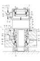
- the mechanical seal 1301 in Example 2 will be described. As shown in FIG. 12, in this embodiment, the mechanical seal 1301 is provided between the rotary shaft 2 of the rotary machine such as a pump or a compressor and the seal cover 1303, and the rotary shaft 2 is interposed via the sleeve 1304.
- the ring-shaped rotary seal rings 20 and 21 fixed to the ring and the ring-shaped fixed seal rings 30 and 31 fixed to the seal cover 1303 and the adapter 1305 are mainly composed of metal bellows members 60 and 61.
- the fixed sealing rings 30 and 31 are urged in the axial direction by the above, so that the sliding surfaces 20a and 21a of the rotary sealing rings 20 and 21 and the sliding surfaces 30a and 31a of the fixed sealing rings 30 and 31 are brought into close contact with each other. It can be slid to seal the sealed fluid.
- the mechanical seal 1301 of the present embodiment is configured as a so-called tandem mechanical seal in which the rotary seal ring 20 and fixed seal ring 30 on the atmosphere side, and the rotary seal ring 21 and fixed seal ring 31 on the inside of the machine face the same direction. ing.
- the holder 9 described in the first embodiment is used for fixing the adapter 1305 to the seal cover 1303 by the holder.
- the holder 9 is not limited to this, and the holder 9 of the first embodiment described above is used.
- the configurations of the modified examples A to M may be applied. It goes without saying that the shapes of the seal cover and the adapter are also changed in accordance with the configuration of the applied holder.
- the holder has been described as being inserted into the housing recess formed in the seal cover or the housing recess formed by the flange portion of the seal cover and the adapter. There is no need to provide an accommodation recess in the flange portion.
- the holders are not limited to four, and a plurality of holders may be arranged in the circumferential direction.
- the adapter may be fixed to the seal cover from the atmosphere side.
- adapter fixing structure using the holder described in the above embodiment may be applied to a single-type mechanical seal.
Abstract
Provided is a mechanical seal in which a rotational force is unlikely to be transmitted to a bolt and in which the bolt can be prevented from loosening. This mechanical seal 1 is provided with: rotating sealing rings 20, 21 which rotate with a rotating shaft 2; stationary sealing rings 30, 31; and an adaptor 5 which holds the stationary sealing rings 30, 31, the adaptor 5 being affixed to a seal cover 3 by bolts 11. The mechanical seal 1 is further provided with a plurality of holders 9 which are in axial contact with the adapter 5, and which are provided with through-holes 9d into which the bodies 11a of the bolts 11 engaged with threaded holes 3f in the seal cover 3 are inserted. The plurality of holders 9 are arranged to surround the rotating shaft 2.
Description
本発明は、メカニカルシール、特にボルトによりアダプタがシールカバーに固定されるメカニカルシールに関する。
The present invention relates to a mechanical seal, particularly a mechanical seal in which an adapter is fixed to a seal cover with bolts.
従来、ポンプやコンプレッサ等の回転機械の回転軸とシールカバーとの間に設けられるメカニカルシールは、回転軸に固定される回転密封環に対して固定密封環を付勢手段によって付勢し、回転密封環と固定密封環の摺動面を互いに密接させた状態で相対回転させることにより、被密封流体を軸封している。また、固定密封環のシールカバーへの固定には、アダプタを用い、アダプタに固定密封環を保持させるとともにアダプタをシールカバーの凹部に軸方向から挿入して固定することで、組み立てが簡単になっている。
Conventionally, a mechanical seal provided between a rotary shaft of a rotary machine such as a pump or a compressor and a seal cover urges a fixed seal ring by a biasing means against a rotary seal ring fixed to the rotary shaft, and rotates. The fluid to be sealed is shaft-sealed by relatively rotating the sliding surfaces of the sealing ring and the fixed sealing ring in close contact with each other. In addition, an adapter is used to fix the fixed sealing ring to the seal cover, and the adapter is held by the adapter, and the adapter is inserted into the recess of the seal cover from the axial direction and fixed, thereby simplifying the assembly. ing.
例えば、特許文献1のメカニカルシールにあっては、外周にOリングを装着したアダプタをシールカバーの凹部に軸方向から挿入した状態で、環状薄板をアダプタの側端とシールカバーの側端にそれぞれ当接させて、頭部付きのボルトを環状薄板の貫通孔に挿通しシールカバーの軸方向に延びる雌ネジ部に螺合させて環状薄板をシールカバーに固定し、アダプタを軸方向に位置決め固定している。しかし、シールカバーの内周とアダプタの外周との間には、Oリングが介在しているだけであるため、シールカバーに対してアダプタが回転しやすく、シール性が低いものであった。
For example, in the mechanical seal of Patent Document 1, an annular thin plate is respectively attached to the side end of the adapter and the side end of the seal cover in a state where the adapter having an O-ring attached to the outer periphery is inserted into the recess of the seal cover from the axial direction. The bolt with head is inserted into the through hole of the annular thin plate and screwed into the female thread extending in the axial direction of the seal cover to fix the annular thin plate to the seal cover, and the adapter is positioned and fixed in the axial direction. is doing. However, since only an O-ring is interposed between the inner periphery of the seal cover and the outer periphery of the adapter, the adapter is easy to rotate with respect to the seal cover, and the sealing performance is low.
一方、特許文献2のメカニカルシールにあっては、シールカバーの凹部の側端にOリングを装着した後、外周にOリングを装着したアダプタをシールカバーの凹部に軸方向から挿入した状態で、皿ネジをシールカバーの軸方向に延びる雌ネジ部に螺合させ該皿ネジの頭部の一部でアダプタを軸方向に押し込むことでシールカバーの凹部の側端のOリングを潰した状態で位置決め固定し、アダプタの回転を抑制しつつシールカバーとアダプタとのシール性を高めている。
On the other hand, in the mechanical seal of Patent Document 2, after attaching an O-ring to the side end of the concave portion of the seal cover, an adapter having an O-ring attached to the outer periphery is inserted into the concave portion of the seal cover from the axial direction. In a state in which the O-ring at the side end of the concave portion of the seal cover is crushed by screwing the countersunk screw into the female screw portion extending in the axial direction of the seal cover and pushing the adapter axially with a part of the head of the countersunk screw Positioning and fixing are performed to improve the sealing performance between the seal cover and the adapter while suppressing the rotation of the adapter.
しかしながら、特許文献2にあっては、皿ネジはアダプタに直接接触する構成であって、アダプタに回転軸からの回転力が加わると、シールカバーに対してアダプタが相対回転することにより、アダプタに当接している皿ネジの頭部に対して回転力が直接伝わってしまうため、皿ネジに緩みが生じやすいという問題があった。
However, in Patent Document 2, the countersunk screw is configured to be in direct contact with the adapter, and when a rotational force from the rotation shaft is applied to the adapter, the adapter rotates relative to the seal cover. Since the rotational force is directly transmitted to the head of the countersunk screw which is in contact, there is a problem that the flat screw is likely to be loosened.
本発明は、このような問題点に着目してなされたもので、ボルトに対して回転力が伝わり難く、かつボルトの緩みを防止することができるメカニカルシールを提供することを目的とする。
The present invention has been made paying attention to such problems, and an object of the present invention is to provide a mechanical seal that is difficult to transmit a rotational force to a bolt and that can prevent the bolt from loosening.
前記課題を解決するために、本発明のメカニカルシールは、
回転軸とともに回転する回転密封環と、固定密封環と、前記固定密封環を保持するアダプタと、を備え、ボルトにより前記アダプタがシールカバーに固定されるメカニカルシールであって、
前記アダプタに軸方向に当接し、前記シールカバーのネジ孔に対して螺挿される前記ボルトの胴部が貫通する貫通孔が設けられているホルダを備え、前記ホルダは、前記回転軸を取り囲むように複数配置されていることを特徴としている。
この特徴によれば、アダプタが複数のホルダのそれぞれの貫通孔を貫通するボルトによりシールカバーに固定されるため、シールカバーに対するアダプタの回転が抑制されるとともに、アダプタに回転力が加わってもホルダが回転力を受けるため、ボルトに対して回転力が伝わり難く、ボルトの緩みを防止することができる。 In order to solve the above problems, the mechanical seal of the present invention is
A mechanical seal comprising a rotary seal ring that rotates together with a rotary shaft, a fixed seal ring, and an adapter that holds the fixed seal ring, wherein the adapter is fixed to a seal cover by a bolt,
A holder that is in axial contact with the adapter and includes a through-hole through which the bolt body screwed into the screw hole of the seal cover passes, the holder surrounding the rotating shaft; It is characterized by being arranged in multiple numbers.
According to this feature, since the adapter is fixed to the seal cover by the bolts penetrating the respective through holes of the plurality of holders, the rotation of the adapter relative to the seal cover is suppressed, and the holder can be applied even if a rotational force is applied to the adapter. Since it receives the rotational force, it is difficult to transmit the rotational force to the bolt, and the bolt can be prevented from loosening.
好適には、前記ホルダは、前記貫通孔の周りに前記ボルトの頭部の底部が当接する内鍔部が形成されている。
これによれば、ボルトの頭部とシールカバーとの間に内鍔部が挟まれた状態で、ホルダをシールカバーに対して押さえつけて固定するため、ホルダの軸方向の位置決め精度がよく、かつホルダをシールカバーに強固に固定することができる。 Preferably, the holder is formed with an inner collar portion around which the bottom portion of the bolt head abuts around the through hole.
According to this, since the holder is pressed against and fixed to the seal cover in a state where the inner flange is sandwiched between the head of the bolt and the seal cover, the positioning accuracy in the axial direction of the holder is good, and The holder can be firmly fixed to the seal cover.
好適には、前記アダプタに対する前記ホルダの当接部は、外径側に延びる外鍔部である。
これによれば、外鍔部によりアダプタをシールカバーに対して押さえつけて固定するため、アダプタをシールカバーに強固に固定することができる。 Suitably, the contact part of the said holder with respect to the said adapter is an outer collar part extended to an outer-diameter side.
According to this, the adapter can be firmly fixed to the seal cover because the adapter is pressed against and fixed to the seal cover by the outer flange portion.
好適には、前記ホルダには、前記ボルトの頭部を収容する収容凹部が設けられている。
これによれば、ボルトの頭部がホルダよりも外側に張り出す量が少ない、または外側に張り出さない。 Preferably, the holder is provided with a housing recess for housing the head of the bolt.
According to this, the amount of the head portion of the bolt that projects outward from the holder is small or does not project outward.
これによれば、ボルトの頭部がホルダよりも外側に張り出す量が少ない、または外側に張り出さない。 Preferably, the holder is provided with a housing recess for housing the head of the bolt.
According to this, the amount of the head portion of the bolt that projects outward from the holder is small or does not project outward.
好適には、前記シールカバーには、前記ホルダを収容する収容凹部が設けられている。
これによれば、ホルダがシールカバーよりも外側に張り出す量が少ない、または外側に張り出さない。 Preferably, the seal cover is provided with an accommodating recess for accommodating the holder.
According to this, the amount of the holder projecting outward from the seal cover is small or does not project outward.
これによれば、ホルダがシールカバーよりも外側に張り出す量が少ない、または外側に張り出さない。 Preferably, the seal cover is provided with an accommodating recess for accommodating the holder.
According to this, the amount of the holder projecting outward from the seal cover is small or does not project outward.
好適には、前記ホルダと前記シールカバーの前記収容凹部とは、螺挿方向視円形に形成されており、かつ嵌合されている。
これによれば、シールカバーの収容凹部に対するホルダの組み付け/組み立てを簡単に行うことができる。 Preferably, the holder and the receiving recess of the seal cover are formed in a circular shape as viewed in the screwing direction and are fitted.
According to this, the assembly / assembly of the holder with respect to the housing recess of the seal cover can be easily performed.
好適には、前記ホルダと前記シールカバーの前記収容凹部とは、螺挿方向視非円形に形成されており、かつ嵌合されている。
これによれば、ホルダがシールカバーの収容凹部に嵌合された状態でアダプタに回転力が加わってもホルダの回転力が規制されるため、ボルトに対して回転力が伝わることがなく、より確実にボルトの緩みを防止することができる。 Preferably, the holder and the receiving recess of the seal cover are formed in a non-circular shape in the screwing direction and are fitted.
According to this, since the rotational force of the holder is regulated even if a rotational force is applied to the adapter in a state where the holder is fitted in the housing recess, the rotational force is not transmitted to the bolt. It is possible to reliably prevent the bolts from loosening.
好適には、前記外鍔部の内径側と前記シールカバーとの間には、前記アダプタが挟まれ、
前記外鍔部の外径側と前記シールカバーとの間には、間隙が形成されている。
これによれば、ボルトを締め付けたときに、シールカバーとの間でアダプタを挟圧するための押圧力をホルダの外鍔部の内径側に集中させることができる。 Preferably, the adapter is sandwiched between the inner diameter side of the outer flange portion and the seal cover,
A gap is formed between the outer diameter side of the outer flange portion and the seal cover.
According to this, when the bolt is tightened, the pressing force for pinching the adapter with the seal cover can be concentrated on the inner diameter side of the outer flange portion of the holder.
好適には、前記ボルトの螺挿方向における前記ホルダと前記シールカバーとの間には、スクイズパッキンが配置されている。
これによれば、ホルダにより押圧されるアダプタによってスクイズパッキンがボルトの螺挿方向に圧縮されるため、シール性が高い。 Preferably, a squeeze packing is disposed between the holder and the seal cover in the screwing direction of the bolt.
According to this, since the squeeze packing is compressed in the screw insertion direction of the bolt by the adapter pressed by the holder, the sealing performance is high.
本発明に係るメカニカルシールを実施するための形態を実施例に基づいて以下に説明する。
Embodiments for carrying out the mechanical seal according to the present invention will be described below based on examples.
実施例1に係るメカニカルシールにつき、図1から図5を参照して説明する。尚、本実施例においては、紙面右側を大気側、紙面左側を機内側として説明する。
The mechanical seal according to the first embodiment will be described with reference to FIGS. In the present embodiment, the right side of the paper will be described as the atmosphere side and the left side of the paper will be described as the inside of the apparatus.
図1に示されるように、本実施例のメカニカルシール1は、ポンプやコンプレッサ等の回転機械の回転軸2とシールカバー3との間に設けられており、スリーブ4を介して回転軸2に固定される円環状の回転密封環20,21と、シールカバー3およびアダプタ5に固定された円環状の固定密封環30,31と、から主に構成され、金属製のベローズ部材60,61によって固定密封環30,31がそれぞれ軸方向に付勢されることにより、回転密封環20,21の摺動面20a,21aと固定密封環30,31の摺動面30a,31aとを互いに密接摺動させ、機内の被密封流体を軸封できるようになっている。尚、本実施のメカニカルシール1は、大気側の回転密封環20および固定密封環30と、機内側の回転密封環21および固定密封環31が反対方向を向く、いわゆるダブル形メカニカルシールとして構成されている。
As shown in FIG. 1, the mechanical seal 1 of this embodiment is provided between a rotary shaft 2 and a seal cover 3 of a rotary machine such as a pump or a compressor, and is connected to the rotary shaft 2 via a sleeve 4. An annular rotary seal ring 20, 21 to be fixed, and an annular fixed seal ring 30, 31 fixed to the seal cover 3 and the adapter 5, are constituted by metal bellows members 60, 61. The fixed sealing rings 30 and 31 are urged in the axial direction, so that the sliding surfaces 20a and 21a of the rotary sealing rings 20 and 21 and the sliding surfaces 30a and 31a of the fixed sealing rings 30 and 31 are in close contact with each other. It can be moved to seal the sealed fluid in the machine. The mechanical seal 1 of the present embodiment is configured as a so-called double-type mechanical seal in which the rotary seal ring 20 and fixed seal ring 30 on the atmosphere side, and the rotary seal ring 21 and fixed seal ring 31 on the inside of the machine face in opposite directions. ing.
回転密封環20,21および固定密封環30,31は、代表的にはSiC(硬質材料)同士またはSiC(硬質材料)とカーボン(軟質材料)の組み合わせで形成されるが、これに限らず、摺動材料はメカニカルシール用摺動材料として使用されているものであれば適用可能である。尚、SiCとしては、ボロン、アルミニウム、カーボン等を焼結助剤とした焼結体をはじめ、成分、組成の異なる2種類以上の相からなる材料、例えば、黒鉛粒子の分散したSiC、SiCとSiからなる反応焼結SiC、SiC-TiC、SiC-TiN等があり、カーボンとしては、炭素質と黒鉛質の混合したカーボンをはじめ、樹脂成形カーボン、焼結カーボン等が利用できる。また、上記摺動材料以外では、金属材料、樹脂材料、表面改質材料(コーティング材料)、複合材料等も適用可能である。
The rotary seal rings 20 and 21 and the fixed seal rings 30 and 31 are typically formed of SiC (hard material) or a combination of SiC (hard material) and carbon (soft material). Any sliding material can be used as long as it is used as a sliding material for a mechanical seal. In addition, as SiC, the material which consists of two or more types of phases from which a component and a composition differ, including the sintered compact which used boron, aluminum, carbon, etc. as a sintering auxiliary agent, for example, SiC, SiC with which the graphite particle was disperse | distributed There are reaction-sintered SiC, SiC-TiC, SiC-TiN, and the like made of Si. As the carbon, resin-molded carbon, sintered carbon, etc. can be used as well as carbon mixed with carbonaceous and graphite. In addition to the sliding material, a metal material, a resin material, a surface modifying material (coating material), a composite material, and the like are also applicable.
図1に示されるように、シールカバー3は、ステンレス鋼からなり、略円筒状に形成され、円筒部3aの内側に回転軸2およびスリーブ4を挿通可能な貫通孔3bが形成されている。シールカバー3の内径側には、大気側にベローズ部材60の一端が固定される第1環状取付部3gと、第1環状取付部3gよりも機内側かつ外径側にフランジ付き円筒状のバッフル8が取り付けられる第2環状取付部3hが形成されており、シールカバー3の内側は段付き状に構成されている。
As shown in FIG. 1, the seal cover 3 is made of stainless steel, is formed in a substantially cylindrical shape, and a through hole 3b through which the rotary shaft 2 and the sleeve 4 can be inserted is formed inside the cylindrical portion 3a. On the inner diameter side of the seal cover 3, a first annular mounting portion 3g having one end of the bellows member 60 fixed to the atmosphere side, and a cylindrical baffle with a flange on the inner side and the outer diameter side of the first annular mounting portion 3g. A second annular attachment portion 3h to which 8 is attached is formed, and the inside of the seal cover 3 is configured in a stepped shape.
図1および図2に示されるように、円筒部3aの機内側の端面部3cには、貫通孔3bの周りに大気側へ凹む環状凹部3dが設けられ、この環状凹部3dの径方向に延びる底面の内径側には、円環状のスクイズパッキン7が挿嵌される環状溝部3eが設けられている。尚、スクイズパッキン7は、弾性体からなるものであればよく、素材はゴム、樹脂、黒鉛等であってもよい。また、環状凹部3dの径方向に延びる底面の外径側、すなわち環状溝部3eよりも外径側には、大気側に向けて軸方向に延びるネジ孔としての雌ネジ孔3fが設けられている。尚、雌ネジ孔3fには、シールカバー3に対してアダプタ5を固定するためのボルト11の胴部11aが螺合される。
As shown in FIGS. 1 and 2, an end surface portion 3c on the inner side of the cylindrical portion 3a is provided with an annular recess 3d recessed toward the atmosphere around the through hole 3b, and extends in the radial direction of the annular recess 3d. An annular groove 3e into which an annular squeeze packing 7 is inserted is provided on the inner diameter side of the bottom surface. The squeeze packing 7 may be made of an elastic body, and the material may be rubber, resin, graphite, or the like. A female screw hole 3f as a screw hole extending in the axial direction toward the atmosphere side is provided on the outer diameter side of the bottom surface extending in the radial direction of the annular recess 3d, that is, on the outer diameter side of the annular groove 3e. . The body 11a of the bolt 11 for fixing the adapter 5 to the seal cover 3 is screwed into the female screw hole 3f.
また、図2および図3に示されるように、円筒部3aの機内側の端面部3cには、雌ネジ孔3fを中心にホルダ9が挿嵌される収容凹部10、いわゆる座ぐり穴が形成されている。収容凹部10は、雌ネジ孔3fの開口端部、すなわち機内側端部から外径方向に直交して連なる環状の底面部10aと、底面部10aの外径側端部から機内側へ延びる第1側面部10bと、第1側面部10bの機内側端部の外径側から直交する方向に延びて連なる外縁面部10cと、外縁面部10cの外径側端部から機内側へ延びる第2側面部10dとにより区画されることにより、段付き円筒状の空間として構成されている。また、第1側面部10bの機内側端部の内径側、すなわち貫通孔3b側は、内径方向において環状凹部3dの径方向に延びる底面と直交して連なっている。尚、収容凹部10は、雌ネジ孔3fとともにシールカバー3の周方向に4等配されている(特に図3参照)。
Further, as shown in FIGS. 2 and 3, a housing recess 10 into which the holder 9 is fitted around a female screw hole 3 f, a so-called counterbore, is formed in the end surface portion 3 c on the machine inner side of the cylindrical portion 3 a. Has been. The housing recess 10 includes an annular bottom surface portion 10a that extends from the opening end portion of the female screw hole 3f, that is, the inner end portion of the female screw hole, perpendicularly to the outer diameter direction, and an inner end extending from the outer diameter side end portion of the bottom surface portion 10a to the inner side. A first side surface portion 10b, an outer edge surface portion 10c extending in a direction orthogonal to the outer diameter side of the inner side edge portion of the first side surface portion 10b, and a second side surface extending inward from the outer diameter side end portion of the outer edge surface portion 10c. By being partitioned by the portion 10d, a stepped cylindrical space is formed. Further, the inner diameter side of the inboard end of the first side surface portion 10b, that is, the through-hole 3b side, is connected to the bottom surface extending in the radial direction of the annular recess 3d in the inner diameter direction. The accommodating recesses 10 are equally arranged in the circumferential direction of the seal cover 3 together with the female screw holes 3f (see particularly FIG. 3).
図1に示されるように、アダプタ5は、ステンレス鋼からなり、フランジ付き円筒状に形成され、円筒部5aと、円筒部5aの大気側端部において外径方向に延びる環状のフランジ部5bから構成され、円筒部5aの内側に回転軸2を挿通可能な貫通孔5cが形成されている。アダプタ5の内径側には、機内側にベローズ部材61の一端が固定される環状取付部5kが形成されている。
As shown in FIG. 1, the adapter 5 is made of stainless steel, is formed in a cylindrical shape with a flange, and includes a cylindrical portion 5 a and an annular flange portion 5 b that extends in the outer diameter direction at the atmospheric end of the cylindrical portion 5 a. The through-hole 5c which is comprised and can penetrate the rotating shaft 2 is formed inside the cylindrical part 5a. On the inner diameter side of the adapter 5, an annular mounting portion 5 k is formed on the inside of the machine, to which one end of the bellows member 61 is fixed.
図1および図2に示されるように、アダプタ5の大気側端部には、円筒部5aよりも大径の取付部5dが設けられ、取付部5dの外周寸法は、シールカバー3の貫通孔3bの開口端部、すなわち機内側端部における内周寸法と略同一に構成されている。また、フランジ部5bの外径部には、大気側の第1外周面5eと、第1外周面5eの機内側端部から内径方向に延び直交して連なる機内側の環状面部5fと、環状面部5fの内径側端部から機内側へ延びる第2外周面5gと、から環状段部5hが形成されている。
As shown in FIG. 1 and FIG. 2, the adapter 5 is provided with an attachment portion 5 d having a diameter larger than that of the cylindrical portion 5 a at the atmospheric end of the adapter 5, and the outer peripheral dimension of the attachment portion 5 d is the through hole of the seal cover 3. The opening end portion of 3b, that is, the inner peripheral size at the inner end portion of the machine is substantially the same. Further, the outer diameter portion of the flange portion 5b includes a first outer peripheral surface 5e on the atmosphere side, an annular surface portion 5f on the inner side of the first outer peripheral surface 5e extending in an inner diameter direction from the inner end portion of the first outer peripheral surface 5e and orthogonally connected, and an annular shape An annular step portion 5h is formed from the second outer peripheral surface 5g extending from the inner diameter side end of the surface portion 5f to the inside of the machine.
また、シールカバー3の貫通孔3bに対してアダプタ5の取付部5dが挿嵌された状態では、シールカバー3の環状凹部3dの径方向に延びる底面に対してアダプタ5のフランジ部5bの大気側の環状面部5mが軸方向に当接している。このとき、アダプタ5のフランジ部5bの外径部に形成される環状段部5h、すなわち第1外周面5eは、シールカバー3の収容凹部10の第1側面部10bと軸方向に連続するように構成されている。また、アダプタ5の環状段部5hを構成する機内側の環状面部5fは、シールカバー3の収容凹部10を構成する外径側の外縁面部10cよりも間隙Δだけ軸方向位置が機内側となるように形成されている。
Further, in a state where the attachment portion 5d of the adapter 5 is inserted into the through hole 3b of the seal cover 3, the atmosphere of the flange portion 5b of the adapter 5 with respect to the bottom surface extending in the radial direction of the annular recess 3d of the seal cover 3 The annular surface portion 5m on the side is in contact with the axial direction. At this time, the annular step portion 5 h formed on the outer diameter portion of the flange portion 5 b of the adapter 5, that is, the first outer peripheral surface 5 e is continuous with the first side surface portion 10 b of the housing recess 10 of the seal cover 3 in the axial direction. It is configured. In addition, the machine-side annular surface part 5f constituting the annular step part 5h of the adapter 5 is located in the machine direction in the axial direction by a gap Δ relative to the outer edge face part 10c on the outer diameter side constituting the accommodating recess 10 of the seal cover 3. It is formed as follows.
次いで、ホルダ9について詳しく説明する。図1~図4に示されるように、ホルダ9は、ステンレス鋼からなり、フランジ付き円筒状に形成され、円筒部9aと、円筒部9aの機内側端部において外径方向に延びる環状の外鍔部および当接部としてのフランジ部9bから構成され、円筒部9aの大気側、すなわちシールカバー3側の内鍔部としての底部9cの径方向の中心には、軸方向に貫通する貫通孔9dが形成されている。また、ホルダ9は、シールカバー3の収容凹部10に挿嵌されることにより、貫通孔9dにボルト11の胴部11aを挿通させてボルト11を保持した状態で、シールカバー3の雌ネジ孔3fに対してボルト11の胴部11aを螺合させることができるようになっている。
Next, the holder 9 will be described in detail. As shown in FIGS. 1 to 4, the holder 9 is made of stainless steel, is formed in a cylindrical shape with a flange, and has a cylindrical portion 9a and an annular outer portion extending in the outer diameter direction at the inner end of the cylindrical portion 9a. A through hole that is formed of a flange portion 9b as a flange portion and a contact portion, and penetrates in the axial direction at the center of the cylindrical portion 9a in the radial direction of the bottom portion 9c as an inner flange portion on the seal cover 3 side. 9d is formed. Further, the holder 9 is inserted into the receiving recess 10 of the seal cover 3 so that the body portion 11a of the bolt 11 is inserted into the through hole 9d and the bolt 11 is held. The body 11a of the bolt 11 can be screwed to 3f.
また、ホルダ9には、円筒部9aと、底部9cの機内側端面とから収容凹部9eが形成され、収容凹部9eには、ボルト11の頭部11bが収容可能となっている。また、ボルト11の頭部11bの径は、胴部11aの径よりも大きく構成され、また、収容凹部9eの径は、貫通孔9dの径よりも大きく構成されている。そのため、ホルダ9によりボルト11を保持した状態で、シールカバー3の雌ネジ孔3fにボルト11の胴部11aを螺合させることにより、収容凹部9eに収容されたボルト11の頭部11bの底部としての大気側端面をホルダ9の底部9cの機内側端面に対して軸方向に圧接させることができる。尚、ホルダ9の収容凹部9eは、円筒状の空間として形成されているが、これに限らず、ボルト11の頭部11bを収容できるものであれば、形状は自由に形成されてよい。
Also, the holder 9 is formed with an accommodation recess 9e from the cylindrical portion 9a and the machine-side end surface of the bottom 9c, and the head 11b of the bolt 11 can be accommodated in the accommodation recess 9e. Moreover, the diameter of the head 11b of the bolt 11 is configured to be larger than the diameter of the trunk portion 11a, and the diameter of the housing recess 9e is configured to be larger than the diameter of the through hole 9d. Therefore, the bottom portion of the head portion 11b of the bolt 11 housed in the housing recess 9e is obtained by screwing the body portion 11a of the bolt 11 into the female screw hole 3f of the seal cover 3 with the bolt 11 held by the holder 9. The end face on the atmosphere side can be pressed against the end face of the bottom portion 9c of the holder 9 in the axial direction. In addition, although the accommodation recessed part 9e of the holder 9 is formed as a cylindrical space, not only this but the shape may be freely formed if it can accommodate the head 11b of the volt | bolt 11. FIG.
さらに、ホルダ9のフランジ部9bは、内径側、すなわち貫通孔3b側がアダプタ5の環状段部5hと軸方向に重なる位置まで張り出しているため、ホルダ9のフランジ部9bの内径側とシールカバー3の環状凹部3dの径方向に延びる底面とでアダプタ5のフランジ部5bの環状段部5hを軸方向に挟み込むことができる。このとき、シールカバー3の環状凹部3dの底部、すなわち環状溝部3eとアダプタ5のフランジ部5bとの間に配置されるスクイズパッキン7がボルト11の螺挿方向に圧縮される。
Further, since the flange portion 9b of the holder 9 protrudes to a position where the inner diameter side, that is, the through hole 3b side overlaps the annular step portion 5h of the adapter 5 in the axial direction, the flange portion 9b of the holder 9 and the seal cover 3 The annular step 5h of the flange portion 5b of the adapter 5 can be sandwiched in the axial direction with the bottom surface extending in the radial direction of the annular recess 3d. At this time, the squeeze packing 7 disposed between the bottom of the annular recess 3 d of the seal cover 3, that is, between the annular groove 3 e and the flange 5 b of the adapter 5 is compressed in the screwing direction of the bolt 11.
次いで、メカニカルシール1の組立手順について説明する。図5に示されるように、先ず、シールカバー3の第1環状取付部3gにベローズ部材60および固定密封環30を固定するとともに、アダプタ5の環状取付部5kにベローズ部材61および固定密封環31を固定する。次に、シールカバー3の貫通孔3bに機内側からスリーブ4を挿通し、スリーブ4の保持部4aに固定される回転密封環20の摺動面20aを固定密封環30の摺動面30aに当接させる。また、シールカバー3の環状溝部3eには、二硫化モリブデングリスを薄く塗布したスクイズパッキン7を挿嵌する。
Next, the assembly procedure of the mechanical seal 1 will be described. As shown in FIG. 5, first, the bellows member 60 and the fixed sealing ring 30 are fixed to the first annular mounting portion 3 g of the seal cover 3, and the bellows member 61 and the fixed sealing ring 31 are fixed to the annular mounting portion 5 k of the adapter 5. To fix. Next, the sleeve 4 is inserted into the through hole 3b of the seal cover 3 from the inside of the machine, and the sliding surface 20a of the rotary sealing ring 20 fixed to the holding portion 4a of the sleeve 4 is changed to the sliding surface 30a of the fixed sealing ring 30. Make contact. Further, a squeeze packing 7 coated with a thin molybdenum disulfide grease is inserted into the annular groove 3 e of the seal cover 3.
次に、バッフル8を機内側からシールカバー3とスリーブ4との間の隙間に挿入する。このとき、バッフル8のフランジ部8aに設けられる切欠部8bに対してシールカバー3の第2環状取付部3hに設けられる係止ピン3mを嵌入させることにより、シールカバー3に対するバッフル8の相対回転が規制される。
Next, the baffle 8 is inserted into the gap between the seal cover 3 and the sleeve 4 from the inside of the machine. At this time, the relative rotation of the baffle 8 relative to the seal cover 3 is achieved by fitting the locking pin 3m provided in the second annular mounting portion 3h of the seal cover 3 into the notch 8b provided in the flange portion 8a of the baffle 8. Is regulated.
次に、アダプタ5の取付部5dをシールカバー3の貫通孔3bに挿嵌し、アダプタ5に固定される固定密封環31の摺動面31aをスリーブ4の保持部4aに固定される回転密封環21の摺動面21aに当接させる。このとき、バッフル8の機内側端部に設けられる切欠部8cに対してアダプタ5の取付部5dに設けられる係止ピン5nを嵌入させることにより、シールカバー3に対するアダプタ5の相対回転が規制される。
Next, the mounting portion 5 d of the adapter 5 is inserted into the through hole 3 b of the seal cover 3, and the sliding surface 31 a of the fixed sealing ring 31 fixed to the adapter 5 is fixed to the holding portion 4 a of the sleeve 4. The ring 21 is brought into contact with the sliding surface 21a. At this time, the relative rotation of the adapter 5 with respect to the seal cover 3 is restricted by fitting the locking pin 5n provided in the mounting portion 5d of the adapter 5 into the notch portion 8c provided in the inner end portion of the baffle 8. The
最後に、シールカバー3の収容凹部10およびアダプタ5の環状段部5hに対してホルダ9を挿嵌し、ホルダ9の貫通孔9dにボルト11の胴部11aを挿通してホルダ9によりボルト11を保持した状態で、シールカバー3の雌ネジ孔3fに対してボルト11の胴部11aを螺合させることにより、シールカバー3に対してアダプタ5が固定される。
Finally, the holder 9 is inserted into the housing recess 10 of the seal cover 3 and the annular step portion 5 h of the adapter 5, and the body portion 11 a of the bolt 11 is inserted into the through hole 9 d of the holder 9. The adapter 5 is fixed to the seal cover 3 by screwing the body portion 11a of the bolt 11 into the female screw hole 3f of the seal cover 3 in a state where the seal cover 3 is held.
尚、シールカバー3の貫通孔3bから露出するスリーブ4の大気側端部には、セットリング12が外嵌されており、メカニカルシール1を組み立てた後、図1に示されるように、スリーブ4に回転軸2を挿通し、セットスクリュ13により周方向に複数箇所で均等に締結することにより、回転軸2に対してメカニカルシール1が取り付けられる。
A set ring 12 is externally fitted to the atmosphere side end of the sleeve 4 exposed from the through hole 3b of the seal cover 3. After the mechanical seal 1 is assembled, as shown in FIG. The mechanical seal 1 is attached to the rotary shaft 2 by inserting the rotary shaft 2 through the screw shaft and evenly fastening the rotary shaft 2 at a plurality of locations in the circumferential direction with the set screw 13.
これによれば、本実施例のメカニカルシール1は、アダプタ5が複数のホルダ9のそれぞれの貫通孔9dを貫通するボルト11によりシールカバー3に固定されるため、シールカバー3に対するアダプタ5の回転が抑制されるとともに、アダプタ5に回転力が加わってもホルダ9が回転力を受けるため、ボルト11に対して回転力が伝わり難く、ボルト11の緩みを防止することができる。
According to this, in the mechanical seal 1 of the present embodiment, the adapter 5 is fixed to the seal cover 3 by the bolts 11 penetrating the through holes 9d of the plurality of holders 9, so that the rotation of the adapter 5 relative to the seal cover 3 is performed. In addition, since the holder 9 receives the rotational force even when a rotational force is applied to the adapter 5, the rotational force is not easily transmitted to the bolt 11, and the bolt 11 can be prevented from loosening.
また、ホルダ9は、貫通孔9dの周りにボルト11の頭部11bの底部としての大気側端面が当接する底部9cが形成されているため、ボルト11の頭部11bとシールカバー3の収容凹部10の底面部10aとの間にホルダ9の底部9cが挟まれた状態で、ホルダ9をシールカバー3に対して押さえつけて固定するため、ホルダ9をシールカバー3に強固に固定することができる。
Further, since the holder 9 is formed with a bottom portion 9c around the through-hole 9d with which an end face on the atmosphere side as a bottom portion of the head portion 11b of the bolt 11 abuts, the head portion 11b of the bolt 11 and the receiving recess of the seal cover 3 Since the holder 9 is pressed against and fixed to the seal cover 3 with the bottom portion 9c of the holder 9 being sandwiched between the bottom surface portion 10a of the holder 10, the holder 9 can be firmly fixed to the seal cover 3. .
また、ホルダ9のフランジ部9bの内径側、すなわち貫通孔3b側によりアダプタ5のフランジ部5bをシールカバー3の環状凹部3dに対して押さえつけて固定するため、アダプタ5をシールカバー3に強固に固定することができる。また、シールカバー3の収容凹部10の底面部10aにホルダ9の底部9cが当接するまでボルト11を締め付ければ、アダプタ5のフランジ部5bの機内側の環状面部5fに対するホルダ9のフランジ部9bの位置が所定の締め付け位置となるため、軸方向の位置決め精度がよく、組み付けが簡単である。
Further, since the flange portion 5b of the adapter 5 is pressed against and fixed to the annular recess 3d of the seal cover 3 by the inner diameter side of the flange portion 9b of the holder 9, that is, the through hole 3b side, the adapter 5 is firmly attached to the seal cover 3. Can be fixed. Further, if the bolt 11 is tightened until the bottom portion 9c of the holder 9 comes into contact with the bottom surface portion 10a of the housing recess 10 of the seal cover 3, the flange portion 9b of the holder 9 with respect to the annular surface portion 5f of the flange portion 5b of the adapter 5 inside the machine. Since this position becomes the predetermined tightening position, the positioning accuracy in the axial direction is good and the assembly is easy.
さらに、ホルダ9のフランジ部9bの内径側とシールカバー3の環状凹部3dの径方向に延びる底面とには、アダプタ5のフランジ部5bが挟まれる一方で、ホルダ9のフランジ部9bの外径側とシールカバー3の収容凹部10の外縁面部10cとの間には、軸方向の間隙Δ(図2参照)が形成されているため、ボルト11を締め付けたときに、ホルダ9をシールカバー3に対して押さえつけてシールカバー3との間でアダプタ5のフランジ部5bを挟圧するための押圧力をホルダ9のフランジ部9bの内径側に集中させることができる。尚、ホルダ9のフランジ部9bの外径側とシールカバー3の収容凹部10の外縁面部10cとは、軸方向に当接していてもよい、すなわち間隙Δを設けなくともよい。
Further, the flange portion 5b of the adapter 5 is sandwiched between the inner diameter side of the flange portion 9b of the holder 9 and the bottom surface extending in the radial direction of the annular recess 3d of the seal cover 3, while the outer diameter of the flange portion 9b of the holder 9 is Since an axial gap Δ (see FIG. 2) is formed between the side and the outer edge surface portion 10c of the housing recess 10 of the seal cover 3, the holder 9 is attached to the seal cover 3 when the bolt 11 is tightened. Accordingly, the pressing force for pressing the flange portion 5 b of the adapter 5 between the seal cover 3 and the seal cover 3 can be concentrated on the inner diameter side of the flange portion 9 b of the holder 9. The outer diameter side of the flange portion 9b of the holder 9 and the outer edge surface portion 10c of the housing recess 10 of the seal cover 3 may be in contact with each other in the axial direction, that is, the gap Δ may not be provided.
また、ボルト11の螺挿方向におけるホルダ9のフランジ部9bの内径側とシールカバー3の環状凹部3dの底部との間には、スクイズパッキン7が配置されているため、ボルト11を締め付けたときのホルダ9の押圧力を受けたアダプタ5のフランジ部5bによってスクイズパッキン7がボルト11の螺挿方向に圧縮され、シール性が高い。このことから、金属製のベローズ部材60,61を用いるような高圧の被密封流体の軸封を行うメカニカルシールを構成することが可能となる。また、アダプタ5とシールカバー3との間にスクイズパッキン7が介在することにより、アダプタ5とシールカバー3との間の摩擦が大きくなるため、シールカバー3に対するアダプタ5の相対回転を抑制することができる。
Further, since the squeeze packing 7 is disposed between the inner diameter side of the flange portion 9b of the holder 9 in the screwing direction of the bolt 11 and the bottom portion of the annular recess 3d of the seal cover 3, the bolt 11 is tightened. The squeeze packing 7 is compressed in the screwing direction of the bolt 11 by the flange portion 5b of the adapter 5 that receives the pressing force of the holder 9, and the sealing performance is high. From this, it becomes possible to constitute a mechanical seal that seals the shaft of a high-pressure sealed fluid using the metal bellows members 60 and 61. In addition, since the squeeze packing 7 is interposed between the adapter 5 and the seal cover 3, friction between the adapter 5 and the seal cover 3 increases, so that the relative rotation of the adapter 5 with respect to the seal cover 3 is suppressed. Can do.
また、ホルダ9には、ボルト11の頭部11bを収容する収容凹部9eが設けられているため、ボルト11の頭部11bがホルダ9よりも外側、すなわち機内側に張り出さず、省スペース化することができる。尚、ホルダ9の収容凹部9eは、ボルト11の頭部11bがホルダ9よりも外側、すなわち機内側に僅かに張り出すように構成されていてもよい。
Further, since the holder 9 is provided with an accommodation recess 9e for accommodating the head portion 11b of the bolt 11, the head portion 11b of the bolt 11 does not protrude outward from the holder 9, that is, the inside of the machine, thus saving space. can do. In addition, the accommodation recessed part 9e of the holder 9 may be comprised so that the head 11b of the volt | bolt 11 may protrude slightly outside the holder 9, ie, an inside of a machine.
また、シールカバー3には、ホルダ9を収容する収容凹部10が設けられているため、ホルダ9がシールカバー3の機内側の端面部3cよりも外側に張り出さず、省スペース化することができる。尚、シールカバー3の収容凹部10は、ホルダ9の一部がシールカバー3の機内側の端面部3cよりも外側すなわち機内側に僅かに張り出すように構成されていてもよい。
Further, since the seal cover 3 is provided with the housing recess 10 for housing the holder 9, the holder 9 does not protrude outward from the end surface portion 3 c on the machine inner side of the seal cover 3, and space can be saved. it can. The housing recess 10 of the seal cover 3 may be configured such that a part of the holder 9 slightly protrudes outside the end surface portion 3c on the machine inner side of the seal cover 3, that is, on the machine inner side.
また、ホルダ9は螺挿方向視円形に形成され、シールカバー3の収容凹部10は、螺挿方向視略円形に形成されており、ホルダ9がシールカバー3の収容凹部10に挿嵌された状態で、ホルダ9がシールカバー3およびアダプタ5に対して相対回転可能であるため、アダプタ5に回転力が加わってもホルダ9が回転力を受けて回転しやすく、ボルト11に対して回転力がより伝わり難く、ボルト11の緩みを防止することができる。尚、ホルダ9は、シールカバー3の収容凹部10に挿嵌された状態で回転可能であれば、例えば螺挿方向視で多角形状に構成されてもよい。また、シールカバー3の収容凹部10に対するホルダ9の組み付け/組み立てを簡単に行うことができる。
The holder 9 is formed in a circular shape as viewed in the screwing direction, and the receiving recess 10 of the seal cover 3 is formed in a substantially circular shape as viewed in the screwing direction, and the holder 9 is inserted into the receiving recess 10 of the seal cover 3. In this state, since the holder 9 can rotate relative to the seal cover 3 and the adapter 5, the holder 9 is easily rotated by receiving the rotational force even if a rotational force is applied to the adapter 5, and the rotational force is applied to the bolt 11. Is more difficult to transmit, and the bolt 11 can be prevented from loosening. Note that the holder 9 may be configured in a polygonal shape as viewed in the screwing direction, for example, as long as the holder 9 can be rotated in a state of being inserted into the housing recess 10 of the seal cover 3. Further, the holder 9 can be easily assembled / assembled with respect to the accommodating recess 10 of the seal cover 3.
また、シールカバー3の周方向に複数設けられる収容凹部10にそれぞれホルダ9を設けることにより、従来のようなシールカバー3の周方向に沿って連続する環状薄板に比べてホルダ9同士の間に周方向に空間を確保することができ、機内側からの伝熱を抑制することができる。また、シールカバー3、アダプタ5、ホルダ9は、同じステンレス鋼を素材としているため、熱膨張によって相対的に応力が作用し難くなっている。
Further, by providing the holders 9 in the housing recesses 10 provided in a plurality in the circumferential direction of the seal cover 3, the holders 9 are located between the holders 9 as compared with the conventional annular thin plate along the circumferential direction of the seal cover 3. Space can be secured in the circumferential direction, and heat transfer from the inside of the machine can be suppressed. Moreover, since the seal cover 3, the adapter 5, and the holder 9 are made of the same stainless steel, stress is relatively difficult to act due to thermal expansion.
次いで、実施例1におけるホルダ9の変形例について説明する。実施例1におけるホルダ9の変形例Aとして、図6(a)に示されるホルダ109は、外径方向に延びるフランジ部を有さない螺挿方向視円形に形成されている。また、シールカバー103は、環状凹部103bが外径側まで形成されている。また、アダプタ105は、フランジ部105bがシールカバー103の環状凹部103bの外径部まで延びており、アダプタ105のフランジ部105bとシールカバー103の環状凹部103bとにより、収容凹部110が形成されている。また、アダプタ105のフランジ部105bには、シールカバー103の雌ネジ孔103hに対応する位置に軸方向に貫通する貫通孔105kが形成されている(図6(c)参照)。
Next, a modified example of the holder 9 in the first embodiment will be described. As a modified example A of the holder 9 in the first embodiment, a holder 109 shown in FIG. 6A is formed in a circular shape as viewed in the screwing direction without a flange portion extending in the outer diameter direction. Further, the seal cover 103 has an annular recess 103b formed to the outer diameter side. The adapter 105 has a flange portion 105 b extending to the outer diameter portion of the annular recess 103 b of the seal cover 103, and an accommodation recess 110 is formed by the flange portion 105 b of the adapter 105 and the annular recess 103 b of the seal cover 103. Yes. A through hole 105k that penetrates in the axial direction is formed in the flange portion 105b of the adapter 105 at a position corresponding to the female screw hole 103h of the seal cover 103 (see FIG. 6C).
また、実施例1におけるホルダ9の変形例Bとして、図6(b)に示されるホルダ209は、外径方向に延びるフランジ部を有さない螺挿方向視スタジアム形に形成されている。また、ホルダ209は、シールカバー103の径方向と直交する方向の端部がそれぞれ切り欠かれており、収容凹部209eは、シールカバー103の径方向と直交する方向に開放する直方体形状に形成されている。尚、変形例Bのホルダ209が適用されるシールカバーおよびアダプタは、前述したシールカバー103およびアダプタ105と同一構成であるため、説明を省略する。また、「切り欠き」は実際に切り欠かれて製造される必要はなく切り欠かれた形状であればよいとう意味である。以下においても同様である。
Further, as a modified example B of the holder 9 in the first embodiment, a holder 209 shown in FIG. 6B is formed in a stadium shape as viewed in the screwing direction without a flange portion extending in the outer diameter direction. In addition, the holder 209 is notched at the end in the direction orthogonal to the radial direction of the seal cover 103, and the housing recess 209 e is formed in a rectangular parallelepiped shape that opens in a direction orthogonal to the radial direction of the seal cover 103. ing. Note that the seal cover and the adapter to which the holder 209 of the modified example B is applied have the same configuration as the seal cover 103 and the adapter 105 described above, and thus description thereof is omitted. Further, the “notch” means that it is not necessary to be actually cut and manufactured, and any shape having a notch may be used. The same applies to the following.
これによれば、変形例A,Bのホルダ109,209は螺挿方向視円形または螺挿方向視スタジアム形に形成され、ホルダ109,209がシールカバー103およびアダプタ105に対して相対回転可能であるため、アダプタ105に回転力が加わってもホルダ109,209が回転力を受けて回転しやすく、ボルト11に対して回転力がより伝わり難く、ボルト11の緩みを防止することができる。また、シールカバー103の収容凹部110に対するホルダ9の組み付け/組み立てを簡単に行うことができる。
According to this, the holders 109 and 209 of the modified examples A and B are formed in a circular shape as viewed in the screwing direction or a stadium shape as viewed in the screwing direction, and the holders 109 and 209 can rotate relative to the seal cover 103 and the adapter 105. Therefore, even if a rotational force is applied to the adapter 105, the holders 109 and 209 are easily rotated by receiving the rotational force, and the rotational force is less easily transmitted to the bolt 11, and the bolt 11 can be prevented from loosening. Further, the assembly / assembly of the holder 9 with respect to the housing recess 110 of the seal cover 103 can be easily performed.
また、実施例1におけるホルダ9の変形例Cとして、図7(a)に示されるホルダ309は、螺挿方向視円形に形成され、シールカバー303の内径側および外径側に対応して略半円状のフランジ部309bがそれぞれ形成されている。また、シールカバー303の収容凹部310は、ホルダ309の形状に合わせて螺挿方向視円形に形成されている(図7(c)参照)。
Further, as a modification C of the holder 9 in the first embodiment, a holder 309 shown in FIG. 7A is formed in a circular shape when viewed in the screwing direction and substantially corresponds to the inner diameter side and the outer diameter side of the seal cover 303. A semicircular flange portion 309b is formed. The accommodation recess 310 of the seal cover 303 is formed in a circular shape in the screwing direction in accordance with the shape of the holder 309 (see FIG. 7C).
また、実施例1におけるホルダ9の変形例Dとして、図7(b)に示されるホルダ409は、螺挿方向視スタジアム形に形成され、シールカバー303の内径側および外径側に対応して略半円状のフランジ部409bがそれぞれ形成されている。また、ホルダ409は、フランジ部409bと直交する方向の端部がそれぞれ切り欠かれるとともに、収容凹部409eは、フランジ部409bと直交する方向に開放する直方体形状に形成されている。尚、変形例Dのホルダ409が適用されるシールカバーは、前述したシールカバー303と同一構成であるため、説明を省略する。
Further, as a variation D of the holder 9 in the first embodiment, a holder 409 shown in FIG. 7B is formed in a stadium shape as viewed in the screwing direction, and corresponds to the inner diameter side and the outer diameter side of the seal cover 303. A substantially semi-circular flange portion 409b is formed. In addition, the holder 409 is notched at the end in the direction orthogonal to the flange portion 409b, and the housing recess 409e is formed in a rectangular parallelepiped shape that opens in the direction orthogonal to the flange portion 409b. In addition, since the seal cover to which the holder 409 of Modification D is applied has the same configuration as the seal cover 303 described above, description thereof is omitted.
また、実施例1におけるホルダ9の変形例Eとして、図8(a)に示されるホルダ509は、螺挿方向視円形に形成され、シールカバー503の内径側に対応してフランジ部509bが形成されている。また、シールカバー503の収容凹部510は、ホルダ509の形状に合わせて螺挿方向視円形に形成されている(図8(c)参照)。
Further, as a variation E of the holder 9 in the first embodiment, a holder 509 shown in FIG. 8A is formed in a circular shape in the screwing direction, and a flange portion 509 b is formed corresponding to the inner diameter side of the seal cover 503. Has been. The accommodation recess 510 of the seal cover 503 is formed in a circular shape in the screwing direction in accordance with the shape of the holder 509 (see FIG. 8C).
また、実施例1におけるホルダ9の変形例Fとして、図8(b)に示されるホルダ609は、螺挿方向視スタジアム形に形成され、シールカバー503の内径側および外径側に対応して略半円状のフランジ部609bがそれぞれ形成されている。また、ホルダ609は、フランジ部609bと直交する方向の端部がそれぞれ切り欠かれるとともに、収容凹部609eは、フランジ部609bと直交する方向に開放する直方体形状に形成されている。尚、変形例Fのホルダ609が適用されるシールカバーは、前述したシールカバー503と同一構成であるため、説明を省略する。
Further, as a variation F of the holder 9 in the first embodiment, a holder 609 shown in FIG. 8B is formed in a stadium shape as viewed in the screwing direction, and corresponds to the inner diameter side and the outer diameter side of the seal cover 503. A substantially semicircular flange portion 609b is formed. In addition, the holder 609 is cut out at the end in the direction orthogonal to the flange portion 609b, and the receiving recess 609e is formed in a rectangular parallelepiped shape that opens in the direction orthogonal to the flange portion 609b. In addition, since the seal cover to which the holder 609 of the modified example F is applied has the same configuration as the seal cover 503 described above, description thereof is omitted.
これによれば、ホルダ309,409,509,609の形状とシールカバー303,503の収容凹部310,510とは、螺挿方向視円形または螺挿方向視スタジアム形に形成されており、かつ嵌合されているため、ホルダ309,409,509,609がシールカバー303,503の収容凹部310,510に嵌合された状態でアダプタ5に回転力が加わってもホルダ309,409,509,609の回転力が規制されるため、ボルト11に対して回転力が伝わることがなく、より確実にボルト11の緩みを防止することができる。また、シールカバー303,503の収容凹部310,510に対するホルダ309,409,509,609の組み付け/組み立てを簡単に行うことができる。
According to this, the shape of the holders 309, 409, 509, 609 and the receiving recesses 310, 510 of the seal covers 303, 503 are formed in a circular shape as viewed in the screwing direction or a stadium shape as viewed in the screwing direction, and fitted. Therefore, the holders 309, 409, 509, and 609 are inserted into the recesses 310 and 510 of the seal covers 303 and 503, and the holders 309, 409, 509, and 609 are applied even when a rotational force is applied to the adapter 5. Therefore, the rotational force is not transmitted to the bolt 11, and the bolt 11 can be prevented from loosening more reliably. Further, the holders 309, 409, 509, and 609 can be easily assembled / assembled with respect to the housing recesses 310 and 510 of the seal covers 303 and 503.
また、実施例1におけるホルダ9の変形例Gとして、図9(a)に示されるホルダ709は、螺挿方向視正方形に形成され、シールカバー703の内径側および外径側に対応してフランジ部709bがそれぞれ形成されている。また、シールカバー703の収容凹部710は、ホルダ709の形状に合わせて螺挿方向視正方形に形成されている(図9(c)参照)。
Further, as a modification G of the holder 9 in the first embodiment, a holder 709 shown in FIG. 9A is formed in a square shape in the screwing direction, and has flanges corresponding to the inner diameter side and the outer diameter side of the seal cover 703. Each portion 709b is formed. The accommodation recess 710 of the seal cover 703 is formed in a square shape in the screwing direction in accordance with the shape of the holder 709 (see FIG. 9C).
また、実施例1におけるホルダ9の変形例Hとして、図9(b)に示されるホルダ809は、螺挿方向視長方形に形成され、シールカバー703の内径側および外径側に対応してフランジ部809bがそれぞれ形成されている。尚、ホルダ809の収容凹部809eは、フランジ部809bと直交する方向に開放する直方体形状に形成されている。尚、変形例Hのホルダ809が適用されるシールカバーは、前述したシールカバー703と同一構成であるため、説明を省略する。
Further, as a modification H of the holder 9 in the first embodiment, a holder 809 shown in FIG. 9B is formed in a rectangular shape in the screwing direction and has flanges corresponding to the inner diameter side and the outer diameter side of the seal cover 703. Each portion 809b is formed. In addition, the accommodation recessed part 809e of the holder 809 is formed in the rectangular parallelepiped shape open | released in the direction orthogonal to the flange part 809b. Note that the seal cover to which the holder 809 of the modified example H is applied has the same configuration as the seal cover 703 described above, and thus the description thereof is omitted.
また、実施例1におけるホルダ9の変形例Iとして、図10(a)に示されるホルダ909は、螺挿方向視正方形に形成され、シールカバー903の内径側に対応してフランジ部909bが形成されている。また、シールカバー903の収容凹部910は、ホルダ909の形状に合わせて螺挿方向視正方形に形成されている(図10(c)参照)。
Further, as a variation I of the holder 9 in the first embodiment, a holder 909 shown in FIG. 10A is formed in a square shape in the screwing direction, and a flange portion 909b is formed corresponding to the inner diameter side of the seal cover 903. Has been. In addition, the accommodation recess 910 of the seal cover 903 is formed in a square shape in the screwing direction according to the shape of the holder 909 (see FIG. 10C).
また、実施例1におけるホルダ9の変形例Jとして、図10(b)に示されるホルダ1009は、螺挿方向視長方形に形成され、シールカバー903の内径側に対応してフランジ部1009bが形成されている。尚、ホルダ1009の収容凹部1009eは、フランジ部1009bと直交する方向に開放する直方体形状に形成されている。尚、変形例Jのホルダ1009が適用されるシールカバーは、前述したシールカバー903と同一構成であるため、説明を省略する。
Further, as a variation J of the holder 9 in the first embodiment, a holder 1009 shown in FIG. 10B is formed in a rectangular shape in the screwing direction, and a flange portion 1009b is formed corresponding to the inner diameter side of the seal cover 903. Has been. In addition, the accommodation recessed part 1009e of the holder 1009 is formed in the rectangular parallelepiped shape open | released in the direction orthogonal to the flange part 1009b. Note that the seal cover to which the holder 1009 of Modification J is applied has the same configuration as the above-described seal cover 903, and thus description thereof is omitted.
また、実施例1におけるホルダ9の変形例Kとして、図11(a)に示されるホルダ1109は、外径方向に延びるフランジ部を有さない螺挿方向視正方形に形成されている。また、シールカバー1103は、環状凹部1103bが外径側まで形成されている。また、アダプタ1105は、フランジ部1105bがシールカバー1103の環状凹部1103bの外径部まで延びており、アダプタ105のフランジ部1105bとシールカバー1103の環状凹部1103bとにより、収容凹部1110が形成されている。また、アダプタ1105のフランジ部1105bには、シールカバー1103の雌ネジ孔1103hに対応する位置に軸方向に貫通する貫通孔1105kが形成されている(図11(c)参照)。
Further, as a modified example K of the holder 9 in the first embodiment, a holder 1109 shown in FIG. 11A is formed in a square in a screwing direction view without a flange portion extending in the outer diameter direction. Further, the seal cover 1103 has an annular recess 1103b formed to the outer diameter side. The adapter 1105 has a flange portion 1105 b extending to the outer diameter portion of the annular recess 1103 b of the seal cover 1103, and an accommodation recess 1110 is formed by the flange portion 1105 b of the adapter 105 and the annular recess 1103 b of the seal cover 1103. Yes. A through hole 1105k that penetrates in the axial direction is formed in the flange portion 1105b of the adapter 1105 at a position corresponding to the female screw hole 1103h of the seal cover 1103 (see FIG. 11C).
また、実施例1におけるホルダ9の変形例Mとして、図11(b)に示されるホルダ1209は、外径方向に延びるフランジ部を有さない螺挿方向視長方形に形成されている。尚、ホルダ1209の収容凹部1209eは、短手方向に開放する直方体形状に形成されている。尚、変形例Mのホルダ1209が適用されるシールカバーおよびアダプタは、前述したシールカバー1103およびアダプタ1105と同一構成であるため、説明を省略する。
Also, as a modification M of the holder 9 in the first embodiment, a holder 1209 shown in FIG. 11B is formed in a rectangular shape in the screwing direction as viewed without a flange portion extending in the outer diameter direction. In addition, the accommodation recessed part 1209e of the holder 1209 is formed in the rectangular parallelepiped shape open | released in a transversal direction. Note that the seal cover and the adapter to which the holder 1209 of the modified example M is applied have the same configuration as the seal cover 1103 and the adapter 1105 described above, and thus the description thereof is omitted.
これによれば、ホルダ709,809,909,1009,1109,1209とシールカバー703,903,1103の収容凹部710,910,1110とは、螺挿方向視非円形に形成されており、かつ嵌合されているため、ホルダ709,809,909,1009,1109,1209がシールカバー703,903,1103の収容凹部710,910,1110に嵌合された状態でアダプタ5,1105に回転力が加わってもホルダ709,809,909,1009,1109,1209の回転力が規制されるため、ボルト11に対して回転力が伝わることがなく、より確実にボルト11の緩みを防止することができる。尚、螺挿方向視非円形に形成されるホルダおよびシールカバーの収容凹部の形状として四角形のものについて説明したが、これに限らず、例えば六角形、八角形等の多角形として形成されていてもよい。
According to this, the holders 709, 809, 909, 1009, 1109, 1209 and the receiving recesses 710, 910, 1110 of the seal covers 703, 903, 1103 are formed in a non-circular shape when viewed in the screwing direction, and are fitted Therefore, a rotational force is applied to the adapters 5 and 1105 in a state where the holders 709, 809, 909, 1009, 1109 and 1209 are fitted in the receiving recesses 710, 910 and 1110 of the seal covers 703, 903 and 1103. However, since the rotational force of the holders 709, 809, 909, 1009, 1109, 1209 is restricted, the rotational force is not transmitted to the bolt 11, and the loosening of the bolt 11 can be prevented more reliably. In addition, although the rectangular thing was demonstrated as a shape of the accommodation recessed part of the holder and seal cover which are formed in a non-circular view in the screwing direction, it is not limited to this, and is formed as a polygon such as a hexagon or an octagon. Also good.
次に、実施例2に係るメカニカルシールにつき、図12を参照して説明する。尚、前記実施例に示される構成部分と同一構成部分については同一符号を付して重複する説明を省略する。
Next, a mechanical seal according to Example 2 will be described with reference to FIG. Note that the same components as those shown in the embodiment are given the same reference numerals and redundant description is omitted.
実施例2におけるメカニカルシール1301について説明する。図12に示されるように、本実施例において、メカニカルシール1301は、ポンプやコンプレッサ等の回転機械の回転軸2とシールカバー1303との間に設けられており、スリーブ1304を介して回転軸2に固定される円環状の回転密封環20,21と、シールカバー1303およびアダプタ1305に固定された円環状の固定密封環30,31と、から主に構成され、金属製のベローズ部材60,61によって固定密封環30,31がそれぞれ軸方向に付勢されることにより、回転密封環20,21の摺動面20a,21aと固定密封環30,31の摺動面30a,31aとを互いに密接摺動させ、被密封流体を軸封できるようになっている。尚、本実施のメカニカルシール1301は、大気側の回転密封環20および固定密封環30と、機内側の回転密封環21および固定密封環31が同じ方向を向く、いわゆるタンデム形メカニカルシールとして構成されている。
The mechanical seal 1301 in Example 2 will be described. As shown in FIG. 12, in this embodiment, the mechanical seal 1301 is provided between the rotary shaft 2 of the rotary machine such as a pump or a compressor and the seal cover 1303, and the rotary shaft 2 is interposed via the sleeve 1304. The ring-shaped rotary seal rings 20 and 21 fixed to the ring and the ring-shaped fixed seal rings 30 and 31 fixed to the seal cover 1303 and the adapter 1305 are mainly composed of metal bellows members 60 and 61. The fixed sealing rings 30 and 31 are urged in the axial direction by the above, so that the sliding surfaces 20a and 21a of the rotary sealing rings 20 and 21 and the sliding surfaces 30a and 31a of the fixed sealing rings 30 and 31 are brought into close contact with each other. It can be slid to seal the sealed fluid. The mechanical seal 1301 of the present embodiment is configured as a so-called tandem mechanical seal in which the rotary seal ring 20 and fixed seal ring 30 on the atmosphere side, and the rotary seal ring 21 and fixed seal ring 31 on the inside of the machine face the same direction. ing.
尚、図12においては、ホルダによるシールカバー1303に対するアダプタ1305の固定に実施例1で説明したホルダ9が使用されているが、これに限らず、ホルダとしては、前述した実施例1のホルダ9の変形例A~Mの構成が適用されてもよい。また、適用されるホルダの構成に合わせてシールカバーおよびアダプタの形状も変更されることは言うまでもない。
In FIG. 12, the holder 9 described in the first embodiment is used for fixing the adapter 1305 to the seal cover 1303 by the holder. However, the holder 9 is not limited to this, and the holder 9 of the first embodiment described above is used. The configurations of the modified examples A to M may be applied. It goes without saying that the shapes of the seal cover and the adapter are also changed in accordance with the configuration of the applied holder.
以上、本発明の実施例を図面により説明してきたが、具体的な構成はこれら実施例に限られるものではない。
Although the embodiments of the present invention have been described with reference to the drawings, the specific configuration is not limited to these embodiments.
例えば、前記実施例において、ホルダは、シールカバーに形成される収容凹部、またはシールカバーとアダプタのフランジ部により形成される収容凹部に対して挿嵌されるものとして説明したが、シールカバーまたはアダプタのフランジ部に収容凹部が設けられる必要はない。
For example, in the above embodiment, the holder has been described as being inserted into the housing recess formed in the seal cover or the housing recess formed by the flange portion of the seal cover and the adapter. There is no need to provide an accommodation recess in the flange portion.
また、ホルダは、4等配されるものに限らず、周方向に複数配置されていればよい。
Further, the holders are not limited to four, and a plurality of holders may be arranged in the circumferential direction.
また、アダプタは、大気側からシールカバーに対して固定されるものであってもよい。
Further, the adapter may be fixed to the seal cover from the atmosphere side.
また、前記実施例で説明したホルダによるアダプタの固定構造は、シングル形メカニカルシールに適用されてもよい。
Further, the adapter fixing structure using the holder described in the above embodiment may be applied to a single-type mechanical seal.
1 メカニカルシール
2 回転軸
3 シールカバー
3f 雌ネジ孔(ネジ孔)
4 スリーブ
5 アダプタ
5b フランジ部
5e 第1外周面
5f 環状面部
5g 第2外周面
5h 環状段部
7 スクイズパッキン
8 バッフル
9 ホルダ
9a 円筒部
9b フランジ部(外鍔部,当接部)
9c 底部(内鍔部)
9d 貫通孔
9e 収容凹部
10 収容凹部
10a 底面部
10b 第1側面部
10c 外縁面部
10d 第2側面部
11 ボルト
11a 胴部
11b 頭部
20,21 回転密封環
20a,21a 摺動面
30,31 固定密封環
30a,31a 摺動面
60,61 ベローズ部材 DESCRIPTION OFSYMBOLS 1 Mechanical seal 2 Rotating shaft 3 Seal cover 3f Female screw hole (screw hole)
4Sleeve 5 Adapter 5b Flange portion 5e First outer peripheral surface 5f Annular surface portion 5g Second outer peripheral surface 5h Annular step portion 7 Squeeze packing 8 Baffle 9 Holder 9a Cylindrical portion 9b Flange portion (outer flange portion, contact portion)
9c Bottom (inner collar)
9d Throughhole 9e Housing recess 10 Housing recess 10a Bottom surface portion 10b First side surface portion 10c Outer edge surface portion 10d Second side surface portion 11 Bolt 11a Body portion 11b Head 20, 21 Rotating seal ring 20a, 21a Sliding surfaces 30, 31 Fixed sealing Ring 30a, 31a Sliding surface 60, 61 Bellows member
2 回転軸
3 シールカバー
3f 雌ネジ孔(ネジ孔)
4 スリーブ
5 アダプタ
5b フランジ部
5e 第1外周面
5f 環状面部
5g 第2外周面
5h 環状段部
7 スクイズパッキン
8 バッフル
9 ホルダ
9a 円筒部
9b フランジ部(外鍔部,当接部)
9c 底部(内鍔部)
9d 貫通孔
9e 収容凹部
10 収容凹部
10a 底面部
10b 第1側面部
10c 外縁面部
10d 第2側面部
11 ボルト
11a 胴部
11b 頭部
20,21 回転密封環
20a,21a 摺動面
30,31 固定密封環
30a,31a 摺動面
60,61 ベローズ部材 DESCRIPTION OF
4
9c Bottom (inner collar)
9d Through
Claims (9)
- 回転軸とともに回転する回転密封環と、固定密封環と、前記固定密封環を保持するアダプタと、を備え、ボルトにより前記アダプタがシールカバーに固定されるメカニカルシールであって、
前記アダプタに軸方向に当接し、前記シールカバーのネジ孔に対して螺挿される前記ボルトの胴部が貫通する貫通孔が設けられているホルダを備え、前記ホルダは、前記回転軸を取り囲むように複数配置されていることを特徴とするメカニカルシール。 A mechanical seal comprising a rotary seal ring that rotates together with a rotary shaft, a fixed seal ring, and an adapter that holds the fixed seal ring, wherein the adapter is fixed to a seal cover by a bolt,
A holder that is in axial contact with the adapter and includes a through-hole through which the bolt body screwed into the screw hole of the seal cover passes, the holder surrounding the rotating shaft; A plurality of mechanical seals are arranged on the surface. - 前記ホルダは、前記貫通孔の周りに前記ボルトの頭部の底部が当接する内鍔部が形成されている請求項1に記載のメカニカルシール。 2. The mechanical seal according to claim 1, wherein the holder has an inner collar portion with which a bottom portion of the head of the bolt abuts around the through hole.
- 前記アダプタに対する前記ホルダの当接部は、外径側に延びる外鍔部である請求項1または2に記載のメカニカルシール。 The mechanical seal according to claim 1 or 2, wherein a contact portion of the holder with respect to the adapter is an outer flange portion extending toward an outer diameter side.
- 前記ホルダには、前記ボルトの頭部を収容する収容凹部が設けられている請求項1ないし3のいずれかに記載のメカニカルシール。 The mechanical seal according to any one of claims 1 to 3, wherein the holder is provided with a housing recess for housing the head of the bolt.
- 前記シールカバーには、前記ホルダを収容する収容凹部が設けられている請求項1ないし4のいずれかに記載のメカニカルシール。 The mechanical seal according to any one of claims 1 to 4, wherein the seal cover is provided with an accommodating recess for accommodating the holder.
- 前記ホルダと前記シールカバーの前記収容凹部とは、螺挿方向視円形に形成されており、かつ嵌合されている請求項5に記載のメカニカルシール。 6. The mechanical seal according to claim 5, wherein the holder and the receiving recess of the seal cover are formed in a circular shape as viewed in the screwing direction and are fitted.
- 前記ホルダと前記シールカバーの前記収容凹部とは、螺挿方向視非円形に形成されており、かつ嵌合されている請求項5に記載のメカニカルシール。 The mechanical seal according to claim 5, wherein the holder and the receiving recess of the seal cover are formed in a non-circular shape when viewed in the screwing direction and are fitted.
- 前記外鍔部の内径側と前記シールカバーとの間には、前記アダプタが挟まれ、
前記外鍔部の外径側と前記シールカバーとの間には、間隙が形成されている請求項3ないし7のいずれかに記載のメカニカルシール。 The adapter is sandwiched between the inner diameter side of the outer flange portion and the seal cover,
The mechanical seal according to any one of claims 3 to 7, wherein a gap is formed between an outer diameter side of the outer flange portion and the seal cover. - 前記ボルトの螺挿方向における前記ホルダと前記シールカバーとの間には、スクイズパッキンが配置されている請求項1ないし8のいずれかに記載のメカニカルシール。 The mechanical seal according to any one of claims 1 to 8, wherein a squeeze packing is disposed between the holder and the seal cover in a screwing direction of the bolt.
Priority Applications (5)
| Application Number | Priority Date | Filing Date | Title |
|---|---|---|---|
| EP19780777.9A EP3779247B1 (en) | 2018-04-03 | 2019-04-02 | Mechanical seal |
| JP2020512247A JP7201666B2 (en) | 2018-04-03 | 2019-04-02 | mechanical seal |
| US16/982,026 US11802623B2 (en) | 2018-04-03 | 2019-04-02 | Mechanical seal |
| CN201980019474.1A CN111868423B (en) | 2018-04-03 | 2019-04-02 | Mechanical seal |
| US18/071,397 US11815183B2 (en) | 2018-04-03 | 2022-11-29 | Mechanical seal |
Applications Claiming Priority (2)
| Application Number | Priority Date | Filing Date | Title |
|---|---|---|---|
| JP2018-071502 | 2018-04-03 | ||
| JP2018071502 | 2018-04-03 |
Related Child Applications (2)
| Application Number | Title | Priority Date | Filing Date |
|---|---|---|---|
| US16/982,026 A-371-Of-International US11802623B2 (en) | 2018-04-03 | 2019-04-02 | Mechanical seal |
| US18/071,397 Division US11815183B2 (en) | 2018-04-03 | 2022-11-29 | Mechanical seal |
Publications (1)
| Publication Number | Publication Date |
|---|---|
| WO2019194154A1 true WO2019194154A1 (en) | 2019-10-10 |
Family
ID=68100561
Family Applications (1)
| Application Number | Title | Priority Date | Filing Date |
|---|---|---|---|
| PCT/JP2019/014573 WO2019194154A1 (en) | 2018-04-03 | 2019-04-02 | Mechanical seal |
Country Status (5)
| Country | Link |
|---|---|
| US (2) | US11802623B2 (en) |
| EP (1) | EP3779247B1 (en) |
| JP (1) | JP7201666B2 (en) |
| CN (1) | CN111868423B (en) |
| WO (1) | WO2019194154A1 (en) |
Citations (5)
| Publication number | Priority date | Publication date | Assignee | Title |
|---|---|---|---|---|
| JP2006519348A (en) * | 2003-02-28 | 2006-08-24 | エイ・ダブリュー・チェスタトン・カンパニー | Automatic detachable spacing mechanism for mechanical seal |
| JP4684421B2 (en) | 1999-03-22 | 2011-05-18 | ドレッサー、ランド、ソシエテ、アノニム | Shaft seal |
| WO2014034582A1 (en) * | 2012-08-29 | 2014-03-06 | イーグル工業株式会社 | Mechanical seal |
| JP2017025994A (en) * | 2015-07-21 | 2017-02-02 | 株式会社デンソー | Fastener |
| JP6196727B2 (en) | 2013-04-24 | 2017-09-13 | イーグルブルクマン ジャーマニー ゲセルシャフト ミト ベシュレンクテル ハフツング ウント コンパニー コマンディトゲゼルシャフト | Mechanical seal with simple structure |
Family Cites Families (14)
| Publication number | Priority date | Publication date | Assignee | Title |
|---|---|---|---|---|
| US2949143A (en) * | 1956-10-12 | 1960-08-16 | Waldes Kohinoor Inc | Fastening means for panels, sheets and the like |
| US3062253A (en) * | 1958-08-26 | 1962-11-06 | Waldes Kohinoor Inc | Bolt and shear sleeve with shear sleeve retracting means |
| US3218906A (en) * | 1962-06-18 | 1965-11-23 | James N Dupree | Captive screw and washer assembly |
| US3743302A (en) * | 1971-12-29 | 1973-07-03 | Klein Schanzlin & Becker Ag | Sealing arrangement |
| JPS6196727U (en) | 1984-11-28 | 1986-06-21 | ||
| CN101131210A (en) | 2006-09-18 | 2008-02-27 | 丹东克隆集团有限责任公司 | Packaging type magnetic shaft sealing device |
| CN101021270A (en) | 2007-03-29 | 2007-08-22 | 合肥华升泵阀有限责任公司 | Mechanical sealing device for high-viscosity medium |
| CN101158361A (en) | 2007-09-28 | 2008-04-09 | 贵州宏福实业开发有限总公司 | Phosphoric acid axial-flow pump dry gas sealing device |
| CN101457841B (en) | 2007-12-13 | 2010-08-25 | 丹东克隆集团有限责任公司 | Mechanical seal device for rubber bellows |
| DE102009018279A1 (en) | 2009-04-21 | 2009-11-19 | Daimler Ag | Screw connection for attaching holder to framework of vehicle, has screw and/or nut with supporting regions and insertion elements that have outside diameter corresponding to inside diameter of boreholes and are arranged in boreholes |
| CN104395654B (en) | 2012-09-11 | 2016-02-17 | 伊格尔工业股份有限公司 | Mechanical seal |
| CN103291930A (en) | 2013-06-27 | 2013-09-11 | 无锡市宏源弹性器材有限公司 | Labyrinth type waterproof sealing device |
| US10352454B2 (en) | 2014-11-04 | 2019-07-16 | Eagle Industry Co., Ltd. | Mechanical seal device |
| CN205479358U (en) | 2016-02-15 | 2016-08-17 | 宜兴市鑫鹏非金属化工设备有限公司 | Clamping apparatus for mechanical seal |
-
2019
- 2019-04-02 JP JP2020512247A patent/JP7201666B2/en active Active
- 2019-04-02 US US16/982,026 patent/US11802623B2/en active Active
- 2019-04-02 WO PCT/JP2019/014573 patent/WO2019194154A1/en unknown
- 2019-04-02 EP EP19780777.9A patent/EP3779247B1/en active Active
- 2019-04-02 CN CN201980019474.1A patent/CN111868423B/en active Active
-
2022
- 2022-11-29 US US18/071,397 patent/US11815183B2/en active Active
Patent Citations (5)
| Publication number | Priority date | Publication date | Assignee | Title |
|---|---|---|---|---|
| JP4684421B2 (en) | 1999-03-22 | 2011-05-18 | ドレッサー、ランド、ソシエテ、アノニム | Shaft seal |
| JP2006519348A (en) * | 2003-02-28 | 2006-08-24 | エイ・ダブリュー・チェスタトン・カンパニー | Automatic detachable spacing mechanism for mechanical seal |
| WO2014034582A1 (en) * | 2012-08-29 | 2014-03-06 | イーグル工業株式会社 | Mechanical seal |
| JP6196727B2 (en) | 2013-04-24 | 2017-09-13 | イーグルブルクマン ジャーマニー ゲセルシャフト ミト ベシュレンクテル ハフツング ウント コンパニー コマンディトゲゼルシャフト | Mechanical seal with simple structure |
| JP2017025994A (en) * | 2015-07-21 | 2017-02-02 | 株式会社デンソー | Fastener |
Also Published As
| Publication number | Publication date |
|---|---|
| EP3779247A4 (en) | 2021-12-29 |
| US11815183B2 (en) | 2023-11-14 |
| EP3779247A1 (en) | 2021-02-17 |
| JP7201666B2 (en) | 2023-01-10 |
| CN111868423B (en) | 2022-08-09 |
| JPWO2019194154A1 (en) | 2021-04-08 |
| CN111868423A (en) | 2020-10-30 |
| EP3779247B1 (en) | 2023-09-13 |
| US11802623B2 (en) | 2023-10-31 |
| US20210018100A1 (en) | 2021-01-21 |
| US20230109060A1 (en) | 2023-04-06 |
Similar Documents
| Publication | Publication Date | Title |
|---|---|---|
| US9243645B2 (en) | Fixture used in rotary machine and method for transporting rotary machine | |
| US4256313A (en) | Universal mechanical seal gland | |
| US5662340A (en) | Fully split cartridge mechanical seal assembly | |
| US4332391A (en) | Universal mechanical seal gland | |
| JPS62270870A (en) | Sealing device | |
| WO2019194154A1 (en) | Mechanical seal | |
| US5538257A (en) | Spring device and method for holding a component on a shaft and pusher seal assembly using same | |
| WO2018012330A1 (en) | Mechanical seal | |
| GB2087514A (en) | A coupling device | |
| US6017036A (en) | Mechanical shaft seal | |
| JP6991943B2 (en) | Split mechanical seal | |
| JP5839716B2 (en) | mechanical seal | |
| JP2023528275A (en) | Single point action low profile lockring for mechanical seals | |
| JP7372831B2 (en) | mechanical seal | |
| JP7154714B2 (en) | mechanical seal | |
| JPH0596552U (en) | Fastening device for shaft and rotating body with retaining ring | |
| JP7234073B2 (en) | double mechanical seal | |
| JP7249252B2 (en) | Shaft seal device | |
| US20200063800A1 (en) | Fixing apparatus for fixing a shaft to a mounting part and actuator of a robot | |
| CN110268184B (en) | Rotary lead-in device and crankshaft assembly | |
| JP4076626B2 (en) | mechanical seal | |
| JP2024033685A (en) | mechanical seal | |
| KR20200024528A (en) | Bearing Support Structure | |
| JP2002089719A (en) | Segment seal |
Legal Events
| Date | Code | Title | Description |
|---|---|---|---|
| 121 | Ep: the epo has been informed by wipo that ep was designated in this application |
Ref document number: 19780777 Country of ref document: EP Kind code of ref document: A1 |
|
| ENP | Entry into the national phase |
Ref document number: 2020512247 Country of ref document: JP Kind code of ref document: A |
|
| NENP | Non-entry into the national phase |
Ref country code: DE |
|
| ENP | Entry into the national phase |
Ref document number: 2019780777 Country of ref document: EP Effective date: 20201103 |