WO2019193895A1 - 加熱炉用搬送ローラー - Google Patents
加熱炉用搬送ローラー Download PDFInfo
- Publication number
- WO2019193895A1 WO2019193895A1 PCT/JP2019/008476 JP2019008476W WO2019193895A1 WO 2019193895 A1 WO2019193895 A1 WO 2019193895A1 JP 2019008476 W JP2019008476 W JP 2019008476W WO 2019193895 A1 WO2019193895 A1 WO 2019193895A1
- Authority
- WO
- WIPO (PCT)
- Prior art keywords
- roller
- outer peripheral
- peripheral surface
- roller body
- heat
- Prior art date
Links
Images


Classifications
-
- B—PERFORMING OPERATIONS; TRANSPORTING
- B65—CONVEYING; PACKING; STORING; HANDLING THIN OR FILAMENTARY MATERIAL
- B65H—HANDLING THIN OR FILAMENTARY MATERIAL, e.g. SHEETS, WEBS, CABLES
- B65H5/00—Feeding articles separated from piles; Feeding articles to machines
- B65H5/06—Feeding articles separated from piles; Feeding articles to machines by rollers or balls, e.g. between rollers
- B65H5/066—Feeding articles separated from piles; Feeding articles to machines by rollers or balls, e.g. between rollers the articles resting on rollers or balls
-
- B—PERFORMING OPERATIONS; TRANSPORTING
- B65—CONVEYING; PACKING; STORING; HANDLING THIN OR FILAMENTARY MATERIAL
- B65G—TRANSPORT OR STORAGE DEVICES, e.g. CONVEYORS FOR LOADING OR TIPPING, SHOP CONVEYOR SYSTEMS OR PNEUMATIC TUBE CONVEYORS
- B65G39/00—Rollers, e.g. drive rollers, or arrangements thereof incorporated in roller-ways or other types of mechanical conveyors
- B65G39/02—Adaptations of individual rollers and supports therefor
- B65G39/07—Other adaptations of sleeves
-
- B—PERFORMING OPERATIONS; TRANSPORTING
- B65—CONVEYING; PACKING; STORING; HANDLING THIN OR FILAMENTARY MATERIAL
- B65H—HANDLING THIN OR FILAMENTARY MATERIAL, e.g. SHEETS, WEBS, CABLES
- B65H5/00—Feeding articles separated from piles; Feeding articles to machines
- B65H5/06—Feeding articles separated from piles; Feeding articles to machines by rollers or balls, e.g. between rollers
-
- C—CHEMISTRY; METALLURGY
- C21—METALLURGY OF IRON
- C21D—MODIFYING THE PHYSICAL STRUCTURE OF FERROUS METALS; GENERAL DEVICES FOR HEAT TREATMENT OF FERROUS OR NON-FERROUS METALS OR ALLOYS; MAKING METAL MALLEABLE, e.g. BY DECARBURISATION OR TEMPERING
- C21D1/00—General methods or devices for heat treatment, e.g. annealing, hardening, quenching or tempering
-
- C—CHEMISTRY; METALLURGY
- C21—METALLURGY OF IRON
- C21D—MODIFYING THE PHYSICAL STRUCTURE OF FERROUS METALS; GENERAL DEVICES FOR HEAT TREATMENT OF FERROUS OR NON-FERROUS METALS OR ALLOYS; MAKING METAL MALLEABLE, e.g. BY DECARBURISATION OR TEMPERING
- C21D9/00—Heat treatment, e.g. annealing, hardening, quenching or tempering, adapted for particular articles; Furnaces therefor
- C21D9/52—Heat treatment, e.g. annealing, hardening, quenching or tempering, adapted for particular articles; Furnaces therefor for wires; for strips ; for rods of unlimited length
- C21D9/54—Furnaces for treating strips or wire
- C21D9/56—Continuous furnaces for strip or wire
- C21D9/562—Details
- C21D9/563—Rolls; Drums; Roll arrangements
-
- F—MECHANICAL ENGINEERING; LIGHTING; HEATING; WEAPONS; BLASTING
- F27—FURNACES; KILNS; OVENS; RETORTS
- F27B—FURNACES, KILNS, OVENS, OR RETORTS IN GENERAL; OPEN SINTERING OR LIKE APPARATUS
- F27B9/00—Furnaces through which the charge is moved mechanically, e.g. of tunnel type; Similar furnaces in which the charge moves by gravity
- F27B9/14—Furnaces through which the charge is moved mechanically, e.g. of tunnel type; Similar furnaces in which the charge moves by gravity characterised by the path of the charge during treatment; characterised by the means by which the charge is moved during treatment
- F27B9/20—Furnaces through which the charge is moved mechanically, e.g. of tunnel type; Similar furnaces in which the charge moves by gravity characterised by the path of the charge during treatment; characterised by the means by which the charge is moved during treatment the charge moving in a substantially straight path tunnel furnace
- F27B9/24—Furnaces through which the charge is moved mechanically, e.g. of tunnel type; Similar furnaces in which the charge moves by gravity characterised by the path of the charge during treatment; characterised by the means by which the charge is moved during treatment the charge moving in a substantially straight path tunnel furnace being carried by a conveyor
- F27B9/2407—Furnaces through which the charge is moved mechanically, e.g. of tunnel type; Similar furnaces in which the charge moves by gravity characterised by the path of the charge during treatment; characterised by the means by which the charge is moved during treatment the charge moving in a substantially straight path tunnel furnace being carried by a conveyor the conveyor being constituted by rollers (roller hearth furnace)
-
- F—MECHANICAL ENGINEERING; LIGHTING; HEATING; WEAPONS; BLASTING
- F27—FURNACES; KILNS; OVENS; RETORTS
- F27D—DETAILS OR ACCESSORIES OF FURNACES, KILNS, OVENS, OR RETORTS, IN SO FAR AS THEY ARE OF KINDS OCCURRING IN MORE THAN ONE KIND OF FURNACE
- F27D3/00—Charging; Discharging; Manipulation of charge
- F27D3/02—Skids or tracks for heavy objects
- F27D3/026—Skids or tracks for heavy objects transport or conveyor rolls for furnaces; roller rails
-
- B—PERFORMING OPERATIONS; TRANSPORTING
- B65—CONVEYING; PACKING; STORING; HANDLING THIN OR FILAMENTARY MATERIAL
- B65G—TRANSPORT OR STORAGE DEVICES, e.g. CONVEYORS FOR LOADING OR TIPPING, SHOP CONVEYOR SYSTEMS OR PNEUMATIC TUBE CONVEYORS
- B65G2201/00—Indexing codes relating to handling devices, e.g. conveyors, characterised by the type of product or load being conveyed or handled
- B65G2201/02—Articles
- B65G2201/0214—Articles of special size, shape or weigh
- B65G2201/022—Flat
-
- B—PERFORMING OPERATIONS; TRANSPORTING
- B65—CONVEYING; PACKING; STORING; HANDLING THIN OR FILAMENTARY MATERIAL
- B65H—HANDLING THIN OR FILAMENTARY MATERIAL, e.g. SHEETS, WEBS, CABLES
- B65H2301/00—Handling processes for sheets or webs
- B65H2301/40—Type of handling process
- B65H2301/44—Moving, forwarding, guiding material
- B65H2301/443—Moving, forwarding, guiding material by acting on surface of handled material
- B65H2301/4432—Moving, forwarding, guiding material by acting on surface of handled material by means having an operating surface contacting only one face of the material, e.g. roller
- B65H2301/44324—Rollers
-
- B—PERFORMING OPERATIONS; TRANSPORTING
- B65—CONVEYING; PACKING; STORING; HANDLING THIN OR FILAMENTARY MATERIAL
- B65H—HANDLING THIN OR FILAMENTARY MATERIAL, e.g. SHEETS, WEBS, CABLES
- B65H2701/00—Handled material; Storage means
- B65H2701/10—Handled articles or webs
- B65H2701/17—Nature of material
- B65H2701/173—Metal
Definitions
- the present invention relates to a transport roller for a heating furnace that uses a transport roller to receive a cold object to be heated in a heating furnace and to carry the heated object to the outside of the heating furnace, and particularly suppresses deformation of the transport roller.
- a transport roller for a heating furnace that uses a transport roller to receive a cold object to be heated in a heating furnace and to carry the heated object to the outside of the heating furnace, and particularly suppresses deformation of the transport roller.
- the heated object is carried into the heating furnace while supporting the heated object at room temperature.
- it is a heating furnace conveying member described in Patent Document 1.
- the thermal shock resistance proposed in Patent Document 2 is relatively It is said that the thermal shock resistance and thermal deformability are high as compared with a transport roller consisting of a low ceramic outer tube and a steel tube or an inner tube made of a heat-resistant alloy.
- red heat of about 900 ° C. to 1000 ° C. is obtained by intermittent conveyance. It may be desired to heat to temperature.
- the high-temperature transport roller installed in the furnace accepts the object to be heated in a cold state. For example, when the object to be heated is heated to a high temperature in a stop period of about 30 seconds. The operation of carrying out rotation out of the furnace is repeated.
- the present invention has been made against the background of the above circumstances, and an object of the present invention is to provide a conveying roller for a heating furnace having local deformation resistance.
- the present inventors have found that the transport roller used in the furnace is in a high temperature state, whereas the heated object carried into the furnace is cold at room temperature. Because of the state, it was assumed that the rapid cooling of the transport roller was the cause of local deformation. And in order to suppress heat transfer, the support roller is provided with a support protrusion protruding to the outer peripheral side to reduce the contact area with the object to be heated, and in order to suppress radiation cooling, the outer peripheral surface of the transfer roller is provided between the support protrusions. It has been found that when a covering shielding member is provided, the occurrence of local deformation in the circumferential direction on the outer peripheral surface of the transport roller is suppressed. The present invention has been made based on such findings.
- the gist of the present invention is that the both ends are supported outside the heating furnace in a state in which a longitudinal shape is formed and the middle part in the longitudinal direction is positioned in the heating furnace.
- a transport roller for a heating furnace for transporting while supporting a heated object a roller body composed of a metal tube made of a heat-resistant alloy, and a predetermined interval in the longitudinal direction of the roller body on the outer peripheral surface of the roller body
- a shielding member covering the space.
- the gist of the second invention is that, in the first invention, the support protrusions are made of a plurality of heat-resistant alloys welded to a plurality of positions at predetermined intervals in the longitudinal direction of the roller body on the outer peripheral surface of the roller body.
- An annular wire or a tubular overlay welding material is an annular wire or a tubular overlay welding material.
- the gist of the third invention is that, in the first invention, the support protrusion is one spiral wire or a spiral overlay welding material made of a heat-resistant alloy that is spirally welded to the outer peripheral surface of the roller body. Consists of
- the gist of the fourth invention is that, in the first invention or the second invention, the shielding member has a thickness equal to or less than a height of the support protrusion from the outer peripheral surface of the roller main body, and the outer periphery of the roller main body. It is composed of one or two or more heat-resistant alloy short tubes fitted between the support protrusions with a predetermined play on the surface.
- the gist of the fifth invention is that, in the first invention or the second invention, the shielding member has a height equal to or less than a height of the support protrusion from the outer peripheral surface of the roller body so as to cover the outer peripheral surface of the roller body. It is comprised from the heat insulating material wound between the said support protrusions by thickness.
- a gist of a sixth invention is that in the third invention, the shielding member has a thickness equal to or less than a height of the support protrusion from the outer peripheral surface of the roller body so as to cover the outer peripheral surface of the roller main body. It is comprised from the heat insulating material wound between the wire-like wire or the said spiral build-up welding material.
- the object to be heated is a support made of a heat-resistant alloy that protrudes higher than the shielding member at a plurality of predetermined intervals in the longitudinal direction of the roller body on the outer peripheral surface of the roller body. It is supported or transported in a state of being supported exclusively by the protrusions. At this time, the support protrusion made of the heat-resistant alloy comes into contact with the cold object to be heated with a slight contact area, so there is little heat transfer from the high temperature roller body to the object to be heated, and heat radiation is generated from the high temperature roller body.
- a shielding member is interposed between the steel plate and the roller body, and radiation cooling from the high-temperature roller body is suppressed by the shielding member, so local deformation that rises continuously in the circumferential direction on the outer peripheral surface of the roller body is suitable. To be suppressed.
- the support protrusions are a plurality of annular shapes made of a heat-resistant alloy that are welded to a plurality of positions at predetermined intervals in the longitudinal direction of the roller body on the outer peripheral surface of the roller body. It consists of a wire or an annular overlay welding material.
- the support protrusion is composed of one spiral wire made of a heat-resistant alloy spirally welded to the outer peripheral surface of the roller body or a spiral overlay welding material. Is done.
- a to-be-heated material is supported by a roller main body exclusively through one spiral wire or a spiral build-up welding material, a cold to-be-heated material may contact the outer peripheral surface of a roller main body directly. This eliminates the deformation of the outer peripheral surface of the roller body.
- a plurality of annular wires are formed because a spiral wire or a helical overlay welding material is formed by continuously welding one heat-resistant metal wire to the outer peripheral surface of the roller body. In comparison, the manufacture becomes easier.
- the shielding member has a thickness not more than the height of the support protrusion from the outer peripheral surface of the roller main body, and has a predetermined play on the outer peripheral surface of the roller main body.
- the shielding member has a thickness not more than a height from the outer peripheral surface of the roller main body so as to cover the outer peripheral surface of the roller main body. It is comprised from the heat insulating material wound around. Thereby, it can be easily configured by winding at least one turn of a belt-shaped heat insulating material woven from fibers of a heat insulating material such as ceramic fiber such as fused silica or alumina and sewing the ends of the belt-shaped heat insulating material.
- the shielding member has a thickness equal to or less than the height of the support protrusion from the outer peripheral surface of the roller body so as to cover the outer peripheral surface of the roller body. Or it is formed in the spiral tubular form from the heat insulating material wound between the said spiral build-up welding materials.
- a belt-shaped heat insulating material woven from a fiber of a heat insulating material such as ceramic fiber such as fused silica or alumina is wound at least once between the spiral wire or the spiral overlay welding material to stop the end of the belt-shaped heat insulating material. Therefore, it can be configured more easily.
- FIG. 2 is a sectional view taken along the line II-II of the intermittent conveyance type steel sheet heating furnace of FIG. It is a figure which expands by notching a part in the longitudinal direction about the conveyance roller for heating furnaces applied to the intermittent conveyance type steel plate heating furnace of FIG. It is an enlarged view which expands and shows a part of conveyance roller for heating furnaces of FIG. It is a figure which expands further the conveyance roller for heating furnaces of FIG. 3 or FIG. 4, and cuts off a part of shielding member, and is demonstrated.
- the outer peripheral surface of the heat-resistant alloy roller body is made of a ceramic film such as oxide, nitride, or carbide to which a coating material is attached using a technique such as spraying, sputtering, or vapor deposition.
- a coating material is attached using a technique such as spraying, sputtering, or vapor deposition.
- the surface is coated. For this reason, the durability of the outer tubular member is enhanced, and adhesion and contamination of the metal oxide or the like to the object to be heated are prevented.
- the roller body made of the heat-resistant alloy, the plurality of annular wires made of the heat-resistant alloy, the one helical wire, and the cylindrical member made of the heat-resistant alloy constituting the short tube Is made of a heat-resistant alloy such as a metal having heat resistance and corrosion resistance, such as stainless steel represented by SUS310S, molybdenum steel, chromium molybdenum steel, ferritic heat-resistant steel, nickel-base alloy, and cobalt alloy.
- a heat-resistant alloy such as a metal having heat resistance and corrosion resistance, such as stainless steel represented by SUS310S, molybdenum steel, chromium molybdenum steel, ferritic heat-resistant steel, nickel-base alloy, and cobalt alloy.
- FIG. 1 is a side view of a heating furnace, for example, an intermittently conveying steel plate heating furnace 12, provided with a heating furnace conveying roller (hereinafter referred to as a conveying roller) 10 according to an embodiment of the present invention.
- 2 is a cross-sectional view taken along the line II-II of the intermittent conveying steel plate heating furnace 12 of FIG.
- the intermittent conveying steel plate heating furnace 12 supports a longitudinal furnace body 18 composed of a heat insulating material 14 that keeps the inside of the furnace in a high temperature state, a casing 16 that covers the heat insulating material 14, and a steel plate 20 that is an object to be heated.
- a plurality of transport rollers 10 arranged in parallel at a predetermined interval to transport from one end of the furnace body 18 to the other end in the longitudinal direction, and a transport roller support that rotatably supports both ends of the transport roller 10
- a device 22 a roller drive device (not shown) that intermittently drives the transport roller 10 rotatably supported by the transport roller support device 22 at a predetermined cycle, for example, a cycle of several tens of seconds, and the interior of the furnace body 18 are heated to a high temperature.
- the furnace body 18 includes a furnace chamber 26 formed in a tunnel shape by being covered by the heat insulating material 14, inlets 28 and outlets 30 formed at both ends in the longitudinal direction of the furnace chamber 26, and conveyance of the steel plate 20. It has a shutter (not shown) that is driven so that the inlet 28 and the outlet 30 are closed when the conveyance roller 10 stops rotating.
- the furnace body 18 of the intermittent conveyance type steel plate heating furnace 12 is parallel to each other in the vicinity of the central part in the vertical direction of both side walls so that the conveyance rollers 10 are penetrated, and a pair of center lines on the both side walls are concentric.
- the furnace body 18 has a cross-sectional view that connects the outside of the furnace body 18 and the furnace chamber 26 under the same condition as the through hole 38 at least above the through hole 38 on both side walls.
- a plurality of circular through holes 40 are provided.
- the transport roller 10 is installed on a base 32 placed horizontally via the roller driving device. Further, for example, a steel plate 20 that has been subjected to a pre-process such as a punching process using a press from a fixed-size high-tensile steel plate is transported to the inlet 28 of the furnace body 18, or is subjected to heat treatment in the furnace chamber 26 and from the outlet 30 of the furnace body 18
- the conveyance stand 36 provided with the conveyance roller 34 which conveys the conveyed steel plate 20 to the next process is intermittently conveyed so that the contact point between the conveyance roller 10 and the conveyance roller 34 and the steel plate 20 is substantially on the same plane.
- the steel plate heating furnace 12 is installed adjacent to both ends in the longitudinal direction.
- the roller drive device has a roller drive motor (not shown) and an output shaft on which a drive sprocket around which a chain 66 (described later) is wound is fixed. Further, the transport roller 34 is preferably configured similarly to the transport roller 10.
- the steel plate 20 transported from the punching process of the high-tensile steel plate by a press to the inlet 28 of the furnace chamber 26 of the intermittent transport steel plate heating furnace 12 by the transport base 36 is carried through the inlet 28 where the shutter is opened, and is heated by the heater 24.
- Heat treatment is performed to heat the steel plate 20 to about 900 ° C. to 1000 ° C. while being intermittently conveyed in a predetermined cycle in the direction of the outlet 30 while being supported by the conveying roller 10 in the furnace chamber 26 heated to a high temperature.
- the steel plate 20 that has been transported by the transport roller 10 to the vicinity of the exit of the furnace chamber 26 and has been heat-treated is intermittently carried out to the outside of the furnace body 18 through the exit 30 where the shutter is opened.
- the unloaded steel plate 20 is transported to the next process, for example, a press process by the transport table 36.
- the plurality of transport rollers 10 are arranged in the vicinity of the lower end in the vertical direction of the furnace chamber 26 with both ends protruding from the plurality of pairs of through holes 38 of the furnace body 18.
- the plurality of transport rollers 10 have a longitudinal shape in the longitudinal direction of the furnace body 18, that is, the direction orthogonal to the transport direction of the steel plate 20, and are arranged in a row in a row in a row in a direction orthogonal to the transport direction.
- the plurality of heaters 24 are respectively fixed to the vicinity of the upper and lower ends in the vertical direction in the furnace chamber 26 with both end portions protruding from the plurality of pairs of through holes 40.
- the plurality of heaters 24 are fixed at regular intervals in a horizontal row in a parallel state in a direction perpendicular to the transfer direction above and below the transport roller 10. Note that a plate-like heater may be used instead of the plurality of heaters 24.
- the transport roller support device 22 includes a support column 42 that is erected adjacent to both side walls of the furnace body 18, and a longitudinal member 44 that is supported by the support column 42 and that is disposed parallel and horizontally to the side wall of the furnace body 18.
- the longitudinal support plate 46 is fixed by being fitted in and fixed to a recess formed by the upper end surface of the longitudinal member 44 being depressed downward leaving both side edges in the longitudinal direction, and the width direction of the support plate 46.
- a plurality of pairs of ball bearings 48 fitted in positions corresponding to the extended lines connecting the plurality of pairs of through holes 38 in the vicinity of the center, and a longitudinal shape rotatably supported in a cantilever manner by the ball bearings 48.
- a pair of support shafts 50 are provided.
- the columnar tip portions 52 of the pair of longitudinal support shafts 50 are fitted into both end portions of the cylindrical conveyance roller 10 in the axial direction, so that the conveyance roller 10 is rotatably supported.
- the end portion 52 of the support shaft 50 fitted with the one end portion is formed in a direction substantially perpendicular to the axial center of the support shaft 50.
- a pin 56 is inserted into the pin hole 54 (see FIG. 3 described later).
- the sprocket wheel (not shown) provided on the output shaft of the roller driving device and the one end side of the conveying roller 10, that is, the base end portion 62 of the support shaft 50 on the side where the pin 56 is inserted are provided.
- a chain 66 is wound around the sprocket wheel 64.
- the transport roller 10 supported by the transport roller support device 22 via the support shaft 50 so as to be rotatable about the axis of the support shaft 50 is driven by the roller via the support shaft 50 and the chain 66 on one end side.
- the steel plate 20 that is rotationally driven by the motor and placed on the transport roller 10 is transported.
- FIG. 3 to 5 are diagrams for explaining in detail the transport roller 10 rotatably supported by the transport roller support device 22.
- FIG. 3 is a diagram for explaining a part of the transport roller 10 applied to the intermittent transport steel plate heating furnace 12 of FIG.
- FIG. 4 is an enlarged view showing a part of the conveyance roller 10 in FIG. 3 in the longitudinal direction.
- FIG. 5 is a view showing the transport roller 10 of FIG. 3 or FIG. 4 with a part of a shielding member attached thereto cut away.
- the conveying roller 10 includes, for example, a roller main body 68 made of a heat-resistant alloy metal tube having a length of about 2200 mm and an outer diameter of about 38.5 mm, and an outer peripheral surface of the roller main body 68.
- a heat-resistant alloy-made support protrusion 70 that protrudes at a plurality of predetermined positions in the longitudinal direction of the roller body 68 and supports the steel plate 20, and a height h of the support protrusion 70 from the outer peripheral surface of the roller body 68 or less.
- a shielding member 72 that covers between the support projections 70 of the roller body 68.
- the length and diameter of the roller body 68 can be appropriately changed as necessary.
- the supporting protrusions 70 are welded at a plurality of positions at predetermined intervals in the longitudinal direction of the roller body 68 on the outer peripheral surface of the roller body 68, respectively, and a plurality of circular cross sections made of a heat resistant alloy having a diameter or thickness of about 1.6 mm ⁇ , for example. Alternatively, it is composed of an annular wire having a rectangular cross section. That is, the height h of the support protrusion 70 from the outer peripheral surface of the roller body 68 is, for example, about 1.6 mm, but is not limited to this value.
- the shielding member 72 has a value less than or less than the height h of the support protrusion 70 from the outer peripheral surface of the roller main body 68, for example, a thickness t of 1.6 mm, and has a predetermined play on the outer peripheral surface of the roller main body 68. It is a heat-resistant alloy short tube fitted between the support protrusions 70. As shown in FIG. 4, the shielding member 72 may be composed of one short tube between the support protrusions 70, or may be composed of two or more short tubes. The total length of the short pipe is, for example, about 10 mm, and is set sufficiently shorter than the interval between the support protrusions 70.
- the inner diameter of the short tube is, for example, about 39 mm, which is sufficiently larger than the outer diameter of the roller body 68, and is preferably set to be equal to or smaller than the outer diameter of the support protrusion 70.
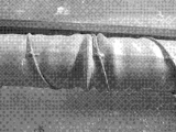
- FIG. 6 is a photograph showing an example of the transport roller 10 configured as described above.
- the present inventors provide an annular support protrusion 70 by welding a SUS310S roller body 68 and a SUS310S wire at an interval of 20 mm to the outer peripheral surface of the roller body 68, and between the support protrusions 70 SUS310S 4 and FIG. 5, and a transfer roller of an embodiment product equivalent to the transfer roller 10 of FIG. 4 and FIG. 5 was prototyped and applied to the above-mentioned intermittent transfer type steel plate heating furnace 12. After the square pipe that has been processed and circulated water in place of the steel plate 20, it is carried on the transport roller in the intermittent transport steel plate heating furnace 12 heated to 900 ° C.
- the conventional type ie, substantially the same as the conveyance roller of the comparative example product 1 with the roller main body 68, which is constructed from a circular tube made of SUS310S with the same length and diameter as the conveyance roller of the above-described example product, similarly SUS310S.
- FIG. 7 is a photograph of Comparative Example Product 1 and a photograph of Comparative Example Product 2.
- FIG. 8 local deformations in which protrusions are formed in the circumferential direction on the surface of the transport roller occurred.
- the conveyance roller of the product of the above example was used, no deformation was observed even after 72 hours.
- the steel plate 20 is protruded higher than the shielding member 72 at a plurality of predetermined positions in the longitudinal direction of the roller body 68 on the outer peripheral surface of the roller body 68. It is conveyed in a state of being supported exclusively by the support protrusions 70 made of a heat resistant alloy.
- the support protrusion 70 made of a heat-resistant alloy comes into contact with the cold-steeled steel plate 20 that is brought in with a small contact area, so that there is little heat transfer from the roller main body 68 to the steel plate 20, and from the high-temperature roller main body 68
- This radiation cooling is shielded by the shielding member 72 provided between the support protrusions 70, so that the rapid cooling of the roller body 68 is suppressed, and the local deformation of the outer peripheral surface of the roller body 68 is suppressed.
- transformation of the outer peripheral surface of the roller main body 68 is suppressed, there will be no deformation
- the steel plate 20 and the outer peripheral surface of the roller body 68 are Since the direct contact is eliminated and the shielding member 72 is interposed between the cold steel plate 20 and the roller body 68, and radiation cooling from the high temperature roller body 68 is suppressed by the shielding member 72, the roller Local deformation that rises in the circumferential direction on the outer peripheral surface of the main body 68 is preferably suppressed.
- the support protrusions 70 are a plurality of annular shapes made of a heat-resistant alloy that are welded to a plurality of positions at predetermined intervals in the longitudinal direction of the roller body 68 on the outer peripheral surface of the roller body 68. Composed of wire.
- the shielding member 72 has a thickness not more than a height h from the outer peripheral surface of the roller main body 68 of the support protrusion 70, and a predetermined play is provided on the outer peripheral surface of the roller main body 68. 1 or two or more heat-resistant alloy short tubes fitted between the annular wires. Thereby, the short pipe can be easily cut by cutting a fixed-size pipe having a thickness not more than the height h from the outer peripheral surface of the roller main body 68 of the support protrusion 70 and an inner diameter larger than the outer diameter of the roller main body 68. Can be configured.
- FIG. 9 is a view corresponding to FIG. 5 showing the transport roller 110 in another embodiment of the present invention.
- the shielding member 72 is a heat-resistant alloy short tube, but instead of the heat-resistant alloy short tube as shown in FIG. 9, the outer peripheral surface of the roller main body 68 between the support protrusions 70. It may be comprised from the heat insulating material wound by the thickness below the height h from the outer peripheral surface of the roller main body 68 of the support protrusion 70 so that it may cover.
- This heat insulating material is comprised from the strip
- the shielding member 172 preferably has a thickness equal to or less than the height h of the support protrusion 70 from the outer peripheral surface of the roller main body 68 so as to cover the outer peripheral surface of the roller main body 68. It is comprised from the heat insulating material wound between the annular wires.
- the shielding member 172 is easily configured by winding at least one turn of a belt-shaped heat insulating material woven from a fiber of a heat insulating material such as a ceramic fiber such as fused silica or alumina and sewing the ends of the belt-shaped heat insulating material. it can.
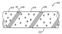
- FIG. 10 is a view corresponding to FIG. 4 showing a main part of the transport roller 210 in another embodiment of the present invention.
- the support protrusion 270 is composed of one spiral wire made of a heat-resistant alloy that is spirally welded to the outer peripheral surface of the roller body 68.
- the shielding member 272 has a thickness not more than a height h from the outer circumferential surface of the roller body 68 of the support projection 270 so as to cover the outer circumferential surface of the roller body 68. It is formed in a spiral tubular shape from the installed heat insulating material.
- the shielding member 272 can be easily configured by winding at least one turn of a belt-shaped heat insulating material woven from a fiber of a heat insulating material such as ceramic fiber such as fused silica or alumina and sewing the ends of the belt-shaped heat insulating material.
- the support protrusion 270 is composed of one spiral wire made of a heat-resistant alloy that is spirally welded to the outer peripheral surface of the roller body 68, so that the steel plate 20 is exclusively used. Since it is supported by the roller body 68 via one spiral wire, it is eliminated that the red-heated steel plate 20 is in direct contact with the outer peripheral surface of the roller main body 68, and deformation of the outer peripheral surface of the roller main body 68 is suppressed. The In addition, since a spiral wire is formed by continuously welding one heat-resistant metal wire to the outer peripheral surface of the roller body 68, compared to the case where a plurality of annular wires are formed, the manufacturing is easier. It becomes easy.
- FIG. 11 is a view corresponding to FIG. 4 showing a main part of the transport roller 310 in another embodiment of the present invention.
- the support protrusion 370 is made of an annular overlay welding material formed on the outer peripheral surface of the roller main body 68 using, for example, laser welding.
- two shielding members 72 each made of a heat-resistant alloy short tube are disposed between the support protrusions 370. Also in this embodiment, the same effects as those of the above-described embodiment can be obtained.
- the transport rollers 10, 110, 210, and 310 of the above-described embodiments have been used in the intermittent transport steel plate heating furnace 12, but other types of heating such as a batch steel plate heating furnace and a continuous steel plate heating furnace. It may also be applied to a furnace.
- the support protrusions 70, 270, and 370 in the above-described embodiment are configured by continuously welding a wire made of a heat-resistant alloy in a ring shape or a spiral shape, but may be discontinuous.
- protrusions such as rivets or pins may be continuously arranged in a circumferential direction or a spiral direction.
- the shielding members 72, 172, and 272 of the above-described embodiments are made of a heat-resistant alloy short tube, a band-shaped heat insulating material or a band-shaped heat insulating material woven from fibers of a heat insulating material such as ceramic fiber such as fused silica or alumina. However, it may be a ceramic short tube.
- the steel plate 20 is used as the object to be heated, but a rectangular parallelepiped steel piece, a sintered alloy part, or the like may be used.
- the support protrusion 270 is composed of a spiral wire welded to the outer peripheral surface of the roller body 68, but may be composed of a spiral overlay welding material.
- Conveying roller Conveying roller for heating furnace
- 12 Intermittent conveying type steel plate heating furnace (heating furnace)
- 20 Steel plate 68: Roller body 70, 270, 370: Support protrusion 72, 172, 272: Shielding member
Landscapes
- Engineering & Computer Science (AREA)
- Mechanical Engineering (AREA)
- Chemical & Material Sciences (AREA)
- General Engineering & Computer Science (AREA)
- Physics & Mathematics (AREA)
- Thermal Sciences (AREA)
- Crystallography & Structural Chemistry (AREA)
- Materials Engineering (AREA)
- Metallurgy (AREA)
- Organic Chemistry (AREA)
- Tunnel Furnaces (AREA)
- Heat Treatments In General, Especially Conveying And Cooling (AREA)
Abstract
耐局所変形性を備えた加熱炉用搬送ローラーを提供する。 鋼板は、ローラー本体68の外周面のローラー本体68の長手方向の所定間隔の複数位置において遮蔽部材72よりも高く突設された耐熱合金製の支持突起70によって専ら支持された状態で搬送される。耐熱合金製の支持突起70は、搬入された冷間状態の鋼板と僅かな接触面積で接触するので、ローラー本体68から鋼板への熱伝動が少なく、高温のローラー本体68からの放射冷却が支持突起70間に設けられた遮蔽部材72によって遮蔽されることによりローラー本体68の急速冷却が抑制され、ローラー本体68の外周面の局所的変形が抑制される。これにより、支持突起70の変形がなく、鋼板の搬送に支障が生じることが解消される。
Description
本発明は、搬送ローラーを用いて冷間の被加熱物を加熱炉内に受け入れ、加熱後の被加熱物を加熱炉外へ搬出する加熱炉用搬送ローラーに関し、特に、搬送ローラーの変形を抑制する技術に関する。
従来、鋼板、焼結合金製成形物などの被加熱物を赤熱させる加熱処理を行なう加熱炉内に、常温の被加熱物を支持しつつ加熱炉内に搬入し、加熱後の被加熱物を搬出するものとして、長手状を成し、長手方向の中間部が加熱炉内に位置させられた状態で両端部がその加熱炉外で支持される、耐熱衝撃性および耐熱変形性の高い搬送ローラーが提案されている。たとえば特許文献1に記載の加熱炉用搬送部材がそれである。これによれば、相対的に耐熱衝撃性および耐腐食性の高い耐熱合金から構成された外側管状部材と、該外側管状部材の内側に位置して、相対的に耐熱変形性の高いセラミックスから構成された内側管状部材とが、耐熱性断熱材から構成された中間部材を介して一体的に重ねられた二重管構造であるため、特許文献2で提案されている、耐熱衝撃性が相対的に低いセラミックス製の外管と鋼管や耐熱合金から成る内管とからなる搬送ローラーと比較して、耐熱衝撃性および熱変形性が高いとされている。
ところで、たとえば高張力鋼製鋼板のプレス前の加熱用として加熱炉が用いられる場合、炉長を短くして工場内に設置スペースを小さくするために、間欠搬送によって900℃~1000℃程度の赤熱温度まで加熱することが望まれる場合がある。このような用途の加熱炉においては、炉内に設置された高温の搬送ローラーは、冷間状態の被加熱物を受け入れ、たとえば30秒程度の停止区間で被加熱物が高温に加熱されると、回転駆動されることで炉外へ搬出するという作動が繰り返えされる。このようにして炉内に用いられる搬送ローラーは、比較的長時間に使用されると、搬送ローラーの外周面に周方向に連なって盛り上がる局所的変形が発生し、被加熱物の搬送に支障が生じるという問題があった。たとえば、被加熱物の搬送方向がずれて定位置に送り出し位置が変化したり、被加熱物が炉壁に干渉して搬送詰まりが発生するなどの問題があった。この問題は、搬送ローラーに内管が設けられていなくても発生する。
本発明は、以上の事情を背景として為されたものであり、その目的とするところは、耐局所変形性を備えた加熱炉用搬送ローラーを提供することにある。
本発明者等は、以上の事情を背景として種々検討を重ねた結果、炉内に用いられる搬送ローラーは高温状態であるのに対して、炉内に搬入された被加熱物は常温で冷間状態にあることから、搬送ローラーが急速冷却されることが局所的変形の原因であると仮定した。そして、熱伝動を抑制するために搬送ローラーに外周側に突き出す支持突起を設けて被加熱物との接触面積を小さくし、放射冷却を抑制するために上記支持突起間に搬送ローラーの外周面を覆う遮蔽部材を設けると、搬送ローラーの外周面に周方向に連なる局所的変形の発生が抑制されることを見いだした。本発明はこのような知見に基づいて為されたものである。
すなわち、本発明の要旨とするところは、長手状を成し、長手方向の中間部が加熱炉内に位置させられた状態で両端部が該加熱炉外で支持され、該加熱炉内において被加熱物を支持しつつ搬送するための加熱炉用搬送ローラーであって、耐熱合金製の金属管から構成されたローラー本体と、前記ローラー本体の外周面の前記ローラー本体の長手方向の所定間隔の複数位置に突設されて前記被加熱物を支持する耐熱合金製の支持突起と、前記支持突起の前記ローラー本体の外周面からの高さ以下の厚みを有し、前記ローラー本体の前記支持突起間を覆う遮蔽部材とを、含むことにある。
第2発明の要旨とするところは、第1発明において、前記支持突起は、前記ローラー本体の外周面の前記ローラー本体の長手方向の所定間隔の複数位置にそれぞれ溶接された耐熱合金製の複数本の環状ワイヤー又は管状肉盛溶接材から構成される。
第3発明の要旨とするところは、第1発明において、前記支持突起は、前記ローラー本体の外周面に螺旋状に溶接された耐熱合金製の1本の螺旋状ワイヤー又は螺旋状肉盛溶接材から構成される。
第4発明の要旨とするところは、第1発明または第2発明において、前記遮蔽部材は、前記支持突起の前記ローラー本体の外周面からの高さ以下の厚みを有し、前記ローラー本体の外周面に所定の遊びを持って前記支持突起間に嵌合された1又は2以上の耐熱合金製短管から構成されたものである。
第5発明の要旨とするところは、第1発明または第2発明において、前記遮蔽部材は、前記ローラー本体の外周面を覆うように前記支持突起の前記ローラー本体の外周面からの高さ以下の厚みで前記支持突起間に巻き付けられた断熱材から構成されたものである。
第6発明の要旨とするところは、第3発明において、前記遮蔽部材は、前記ローラー本体の外周面を覆うように前記支持突起の前記ローラー本体の外周面からの高さ以下の厚みで前記螺旋状ワイヤー又は前記螺旋状肉盛溶接材間に巻き付けられた断熱材から構成されたものである。
第1発明の加熱炉用搬送ローラーによれば、被加熱物は、ローラー本体の外周面のローラー本体の長手方向の所定間隔の複数位置に遮蔽部材よりも高く突設された耐熱合金製の支持突起によって専ら支持された状態で支持され或いは搬送される。このとき、耐熱合金製の支持突起は、冷間の被加熱物と僅かな接触面積で接触するので、高温のローラー本体から被加熱物への熱伝動が少なく、高温のローラー本体から熱放射が支持突起間に設けられた遮蔽部材によって遮蔽されることによりローラー本体の急速冷却が抑制され、ローラー本体の外周面の局所的変形が抑制される。このように、ローラー本体の外周面の局所的変形が抑制されるので、支持突起の変形もなく、被加熱物の搬送に支障が生じることが解消される。特に、間欠搬送の停止区間において冷間の鋼板を回転停止した状態で支持する高温の搬送ローラーでは、冷間の鋼板がローラー本体の外周面に直接接触することが解消されるとともに、冷間の鋼板とローラー本体との間に遮蔽部材が介在しており、高温のローラー本体からの放射冷却が遮蔽部材により抑制されるので、ローラー本体の外周面に周方向に連なって盛り上がる局所的変形が好適に抑制される。
第2発明の加熱炉用搬送ローラーによれば、前記支持突起は、前記ローラー本体の外周面の前記ローラー本体の長手方向の所定間隔の複数位置にそれぞれ溶接された耐熱合金製の複数本の環状ワイヤー又は環状肉盛溶接材から構成される。これにより、被加熱物が専ら複数本の環状ワイヤー又は環状肉盛溶接材を介してローラー本体により支持されるので、冷間の被加熱物がローラー本体の外周面に直接接触することが解消され、ローラー本体の外周面の変形が抑制される。
第3発明の加熱炉用搬送ローラーによれば、前記支持突起は、前記ローラー本体の外周面に螺旋状に溶接された耐熱合金製の1本の螺旋状ワイヤー又は螺旋状肉盛溶接材から構成される。これにより、被加熱物が専ら1本の螺旋状ワイヤー又は螺旋状肉盛溶接材を介してローラー本体により支持されるので、冷間の被加熱物がローラー本体の外周面に直接接触することが解消され、ローラー本体の外周面の変形が抑制される。また、1本の耐熱金属製のワイヤーをローラー本体の外周面に連続的に溶接することにより螺旋状ワイヤー又は螺旋状肉盛溶接材が形成されるので、複数本の環状ワイヤーを構成する場合に比較して、製造が容易となる。
第4発明の加熱炉用搬送ローラーによれば、前記遮蔽部材は、前記支持突起の前記ローラー本体の外周面からの高さ以下の厚みを有し、前記ローラー本体の外周面に所定の遊びを持って前記支持突起間に嵌合された1又は2以上の耐熱合金製短管である。これにより、前記支持突起の前記ローラー本体の外周面からの高さ以下の厚みを有し且つ前記ローラー本体の外径より大きい内径を有する定寸の管材を切断することで短管を容易に構成することができる。
第5発明の加熱炉用搬送ローラーによれば、前記遮蔽部材は、前記ローラー本体の外周面を覆うように前記支持突起の前記ローラー本体の外周面からの高さ以下の厚みで前記支持突起間に巻き付けられた断熱材から構成されたものである。これにより、溶融シリカやアルミナ等のセラミック繊維などの断熱材料の繊維から織られた帯状断熱材を少なくとも1周巻き付けて帯状断熱材の端を縫い合わせることで、容易に構成できる。
第6発明の加熱炉用搬送ローラーによれば、前記遮蔽部材は、前記ローラー本体の外周面を覆うように前記支持突起の前記ローラー本体の外周面からの高さ以下の厚みで前記螺旋状ワイヤー又は前記螺旋状肉盛溶接材間に巻き付けらされた断熱材から螺旋管状に形成されたものである。これにより、溶融シリカやアルミナ等のセラミック繊維などの断熱材料の繊維から織られた帯状断熱材を螺旋状ワイヤー又は前記螺旋状肉盛溶接材間に少なくとも1回巻き付けて帯状断熱材の端を止めることで、一層容易に構成できる。
本発明の一実施形態において、前記耐熱合金製のローラー本体の外周面は、溶射、スパッタ、蒸着などの手法を用いて被膜原料を付着させた酸化物、窒化物、炭化物などのセラミックスの膜によりその表面がコーティングされたものである。このため、外側管状部材の耐久性が高められるとともに、被加熱物に対する金属酸化物などの付着や汚れが防止される。
また、本発明の一実施形態において、前記耐熱合金製のローラー本体、前記耐熱合金製の複数本の環状ワイヤー、前記1本の螺旋状ワイヤー、および前記短管を構成する耐熱合金製円筒状部材は、たとえばSUS310Sに代表されるステンレス鋼、モリブデン鋼、クロムモリブデン鋼、フェライト系耐熱鋼、ニッケル基合金、コバルト合金などの耐熱性、耐腐食性を有する金属などの耐熱合金から構成される。
以下、本発明の被加熱物を加熱する加熱炉に用いられる加熱炉用搬送ローラーの一実施例について図面を参照して詳細に説明する。
図1は本発明の一実施例の加熱炉用搬送ローラー(以下、搬送ローラーという)10を備える加熱炉たとえば間欠搬送式鋼板加熱炉12の側面図である。図2は、図1の間欠搬送式鋼板加熱炉12のII-II視断面図である。間欠搬送式鋼板加熱炉12は、炉内を高温状態に保つ断熱材14と、断熱材14を覆うケーシング16とから成る長手状の炉体18と、被加熱物である鋼板20を支持しながら炉体18の長手方向の一端部から他端部へと搬送するために所定間隔で平行に配置された複数本の搬送ローラー10と、搬送ローラー10の両端部を回転可能に支持する搬送ローラー支持装置22と、搬送ローラー支持装置22により回転可能に支持された搬送ローラー10を所定の周期たとえば数十秒の周期で間欠的に回転駆動する図示しないローラー駆動装置と、炉体18内部を高温に加熱する長手状のヒーター24とを備えている。炉体18は、断熱材14により四方が覆われることでトンネル状に形成された炉室26と、炉室26の長手方向の両端部に形成された入口28および出口30と、鋼板20の搬送停止時すなわち搬送ローラー10の回転停止時に入口28および出口30が閉じられるように駆動させられる図示しないシャッターとを有している。
間欠搬送式鋼板加熱炉12の炉体18は、搬送ローラー10を貫通させるために、両側壁の上下方向中央部付近において、互いに平行に且つその両側壁における一対の中心線が同心となるように長手方向に所定の間隔で炉体18外部と炉室26とを繋ぐように炉体18の両側壁を貫通して形成された断面略円形状の複数対の貫通穴38を備えている。また、炉体18は、ヒーター24を貫通させるために、両側壁の少なくとも上記貫通穴38よりも上方において、上記貫通穴38と同様の条件で炉体18外部と炉室26とを繋ぐ断面略円形状の複数対の貫通穴40を備えている。
図1に詳しく示すように、搬送ローラー10は、水平に置かれた基台32の上に前記ローラー駆動装置を介して設置される。また、たとえば定寸の高張力鋼板からプレスによる打ち抜き工程など前工程を経た鋼板20を炉体18の入口28へと搬送する、あるいはたとえば炉室26において熱処理が施され炉体18の出口30から搬出された鋼板20を次工程へと搬送する搬送ローラー34を備えた搬送台36が、搬送ローラー10および搬送ローラー34と鋼板20との間の接触点が略同一面上になるように間欠搬送式鋼板加熱炉12の長手方向の両端部に隣接して設置されている。なお、上記ローラー駆動装置は、図示しないローラー駆動モータおよび後述のチェーン66が巻き掛けられた駆動スプロケットが固定された出力軸とを有している。また、搬送ローラー34は、好適には、搬送ローラー10と同様に構成される。
たとえばプレスによる高張力鋼板の打ち抜き工程から搬送台36により間欠搬送式鋼板加熱炉12の炉室26の入口28まで搬送された鋼板20は、シャッターが開けられた入口28を通じて搬入され、ヒーター24により高温に昇温された炉室26内を、搬送ローラー10により支持されながら出口30方向へ所定の周期で間欠的に搬送されつつ900℃~1000℃程度に鋼板20を加熱する熱処理が施される。炉室26の出口付近まで搬送ローラー10により搬送され熱処理が終了した鋼板20は、シャッターの開けられた出口30を通じて炉体18外部へと間欠的に搬出される。搬出された鋼板20は搬送台36により次工程たとえばプレス工程へと搬送される。
図2において示されるように、複数本の搬送ローラー10は、その両端部が炉体18の複数対の貫通穴38のそれぞれから突き出した状態で炉室26の上下方向下端部付近に配置されている。これら複数本の搬送ローラー10は、炉体18の長手方向すなわち鋼板20の移送方向と直交する方向へ長手状を成し、移送方向と直交する方向へ並列状態で横一列に一定間隔で配列されている。また、複数本のヒーター24はその両端部が複数対の貫通穴40のそれぞれから突き出した状態で、炉室26内の上下方向上端部付近および下端部付近にそれぞれ固設されている。これら複数本のヒーター24は搬送ローラー10の上方および下方において移送方向と直交する方向へ並列状態で横一列に一定間隔で固設されている。なお、これら複数本のヒーター24に替えて、プレート状のヒーターが用いられてもよい。
搬送ローラー支持装置22は、炉体18の両側壁に隣接して立設された支柱42と、支柱42によって支えられ、炉体18の側壁に平行且つ水平に配設された長手状部材44と、長手状部材44の上端面が長手方向両側縁部を残して下方向へ陥入して形成された凹部に嵌めこまれて固定された長手状の支持板46と、支持板46の幅方向中央部付近における複数対の貫通穴38のそれぞれを結ぶ延長線上に対応する位置に嵌め着けられた複数対のボールベアリング48と、そのボールベアリング48によって片持状に回転可能に支持された長手状の一対の支持軸50とを備えている。
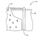
長手状の一対の支持軸50の円柱状の先端部52が円筒状の搬送ローラー10の両端部にそれぞれ軸心方向へ嵌め入れられることにより、搬送ローラー10が回転可能に支持されている。そして、搬送ローラー10の一端部においては、その一端部と嵌合された支持軸50の先端部52における長手方向中央側付近とに支持軸50の軸心と略垂直方向へ貫通して形成されたピン穴54(後述の図3参照)にピン56が挿し込まれている。また、前記ローラー駆動装置の前記出力軸に設けられた図示しないスプロケットホイールと搬送ローラー10の一端部側、すなわちピン56が挿し込まれている側の支持軸50の基端部62に設けられたスプロケットホイール64との間にはチェーン66が巻き掛けられている。
これにより、搬送ローラー支持装置22により支持軸50を介して支持軸50の軸心まわりに回転可能に支持された搬送ローラー10は、その一端部側の支持軸50およびチェーン66を介してローラー駆動モータにより回転駆動され、搬送ローラー10の上に載置された鋼板20を搬送する。
図3乃至図5は、搬送ローラー支持装置22により回転可能に支持された搬送ローラー10について詳しく説明する図である。図3は図1の間欠搬送式鋼板加熱炉12に適用された搬送ローラー10についてその長手方向の一部を切断して説明する図である。図4は、図3における搬送ローラー10の長手方向の一部を拡大して示す図である。図5は、図3または図4の搬送ローラー10を、それに装着された遮蔽部材の一部を切り欠いて示す図である。
図3乃至図5において、搬送ローラー10は、たとえば、2200mm程度の長さおよび38.5mm程度の外径を有する耐熱合金製の金属管から構成されたローラー本体68と、ローラー本体68の外周面においてローラー本体68の長手方向の所定間隔の複数位置に突設されて鋼板20を支持する耐熱合金製の支持突起70と、支持突起70のローラー本体68の外周面からの高さh以下或いは未満の厚みtを有し、ローラー本体68の支持突起70間を覆う遮蔽部材72とを、備えている。上記ローラー本体68の長さおよび径は、必要に応じて適宜変更され得る。
支持突起70は、ローラー本体68の外周面においてローラー本体68の長手方向の所定間隔の複数位置においてそれぞれ溶接された、たとえば1.6mmΦ程度の径或いは厚みを有する耐熱合金製の複数本の断面円形或いは断面矩形の環状ワイヤーから構成される。すなわち、支持突起70のローラー本体68の外周面からの高さhは、たとえば1.6mm程度であるが、この値に限定されない。
遮蔽部材72は、支持突起70のローラー本体68の外周面からの高さh以下或いは未満の値、たとえば1.6mmの厚みtを有し、ローラー本体68の外周面に所定の遊びを持って支持突起70の間に嵌合された耐熱合金製短管である。遮蔽部材72は、支持突起70の間において、図4に示されるように1個の短管から構成されてもよいし、2個以上の短管から構成されてもよい。短管の全長は、たとえば10mm程度であり、支持突起70の間隔よりも十分に短く設定される。また、短管の内径は、たとえば39mm程度であり、ローラー本体68の外径よりも十分に大きく、好適には、支持突起70の外径以下に設定される。図6は、このように構成された搬送ローラー10の一例を示す写真である。
[搬送試験]
本発明者等は、SUS310S製のローラー本体68と、そのローラー本体68の外周面に20mm間隔でSUS310S製のワイヤーを溶接することで環状の支持突起70を設け、それら支持突起70間にSUS310S製の短管を嵌め入れることで構成した、図4,図5の搬送ローラー10と同等の実施例品の搬送ローラーを試作して前述の間欠搬送式鋼板加熱炉12に適用し、コの字形に加工されて内部に水を循環させた角パイプを、鋼板20に替えて、900℃以上に加熱された間欠搬送式鋼板加熱炉12内の搬送ローラ上に搬入して30秒停止させた後、間欠搬送式鋼板加熱炉12から搬出するという搬送動作を、搬入搬出時間が10秒、停止時間が30秒の合計である40秒タクトで繰り返す、実際よりも厳しい条件の加速搬送試験を行なった。また、SUS310S製の円管から上記実施例品の搬送ローラーと同様の長さおよび径で構成された従来形式すなわち実質的にローラー本体68のままの比較例品1の搬送ローラーと、同様にSUS310S製の円管から上記実施例品の搬送ローラーと同様の長さおよび径で構成されたローラー本体68の外周面に、螺旋状に溶接された耐熱合金製の1本の螺旋状ワイヤーから構成される支持突起70を設け、遮蔽部材72を備えない比較例品2の搬送ローラーとを作製し、それら比較例品1の搬送ローラーおよび比較例品2の搬送ローラーを用いて上記の加速搬送試験と同様の条件で搬送試験を行なった。
本発明者等は、SUS310S製のローラー本体68と、そのローラー本体68の外周面に20mm間隔でSUS310S製のワイヤーを溶接することで環状の支持突起70を設け、それら支持突起70間にSUS310S製の短管を嵌め入れることで構成した、図4,図5の搬送ローラー10と同等の実施例品の搬送ローラーを試作して前述の間欠搬送式鋼板加熱炉12に適用し、コの字形に加工されて内部に水を循環させた角パイプを、鋼板20に替えて、900℃以上に加熱された間欠搬送式鋼板加熱炉12内の搬送ローラ上に搬入して30秒停止させた後、間欠搬送式鋼板加熱炉12から搬出するという搬送動作を、搬入搬出時間が10秒、停止時間が30秒の合計である40秒タクトで繰り返す、実際よりも厳しい条件の加速搬送試験を行なった。また、SUS310S製の円管から上記実施例品の搬送ローラーと同様の長さおよび径で構成された従来形式すなわち実質的にローラー本体68のままの比較例品1の搬送ローラーと、同様にSUS310S製の円管から上記実施例品の搬送ローラーと同様の長さおよび径で構成されたローラー本体68の外周面に、螺旋状に溶接された耐熱合金製の1本の螺旋状ワイヤーから構成される支持突起70を設け、遮蔽部材72を備えない比較例品2の搬送ローラーとを作製し、それら比較例品1の搬送ローラーおよび比較例品2の搬送ローラーを用いて上記の加速搬送試験と同様の条件で搬送試験を行なった。
上記の搬送試験において、比較例品1の搬送ローラーおよび比較例品2の搬送ローラーでは、搬送時間が36時間経過すると、比較例品1の写真である図7および比較例品2の写真である図8にそれぞれ示すように、搬送ローラーの表面に凸条が周方向に形成される局所的な変形がそれぞれ発生した。これに対して、上記実施例品の搬送ローラーを用いた場合には、72時間経過しても変形は観察されなかった。
上述のように、本実施例の搬送ローラー10によれば、鋼板20は、ローラー本体68の外周面のローラー本体68の長手方向の所定間隔の複数位置において遮蔽部材72よりも高く突設された耐熱合金製の支持突起70によって専ら支持された状態で搬送される。このとき、耐熱合金製の支持突起70は、搬入された冷間状態の鋼板20と僅かな接触面積で接触するので、ローラー本体68から鋼板20への熱伝動が少なく、高温のローラー本体68からの放射冷却が支持突起70間に設けられた遮蔽部材72によって遮蔽されることによりローラー本体68の急速冷却が抑制され、ローラー本体68の外周面の局所的変形が抑制される。このように、ローラー本体68の外周面の局所的変形が抑制されるので、支持突起70の変形がなく、鋼板20の搬送に支障が生じることが解消される。特に、本実施例のように、間欠搬送の停止区間において、搬入された冷間の鋼板20を回転停止した状態で支持する高温の搬送ローラー10では、鋼板20とローラー本体68の外周面との直接接触が解消されるとともに、冷間の鋼板20とローラー本体68との間に遮蔽部材72が介在しており、高温のローラー本体68からの放射冷却が遮蔽部材72により抑制されるので、ローラー本体68の外周面に周方向に連なって盛り上がる局所的変形が好適に抑制される。
また、本実施例の搬送ローラー10によれば、支持突起70は、ローラー本体68の外周面のローラー本体68の長手方向の所定間隔の複数位置にそれぞれ溶接された耐熱合金製の複数本の環状ワイヤーから構成される。これにより、鋼板20が専ら複数本の環状ワイヤーを介してローラー本体68により支持されるので、赤熱された鋼板20がローラー本体68の外周面に直接接触することが解消され、ローラー本体68の外周面の変形が抑制される。
また、本実施例の搬送ローラー10によれば、遮蔽部材72は、支持突起70のローラー本体68の外周面からの高さh以下の厚みを有し、ローラー本体68の外周面に所定の遊びを持って前記環状ワイヤー間に嵌合された1又は2以上の耐熱合金製短管である。これにより、支持突起70のローラー本体68の外周面からの高さh以下の厚みを有し且つローラー本体68の外径より大きい内径を有する定寸の管材を切断することで短管を容易に構成することができる。
次に、本発明の他の実施例を説明する。なお、以下の実施例において前記実施例と実質的に共通する部分には同一の符号を付して詳しい説明を省略する。
図9は、本発明の他の実施例における搬送ローラー110を示す図5に相当する図である。図5では、遮蔽部材72は耐熱合金製短管であったが、図9に示す遮蔽部材172のように、耐熱合金製短管に替えて、支持突起70の間においてローラー本体68の外周面を覆うように支持突起70のローラー本体68の外周面からの高さh以下の厚みで巻き付けられた断熱材から構成されてもよい。この断熱材は、たとえば、溶融シリカやアルミナ等のセラミック繊維などの断熱材料の繊維から織られた帯状断熱材から構成される。
本実施例の搬送ローラー110によれば、遮蔽部材172は、好適には、ローラー本体68の外周面を覆うように支持突起70のローラー本体68の外周面からの高さh以下の厚みで前記環状ワイヤー間に巻き付けられた断熱材から構成されたものである。この場合には、遮蔽部材172は、溶融シリカやアルミナ等のセラミック繊維などの断熱材料の繊維から織られた帯状断熱材を少なくとも1周巻き付けて帯状断熱材の端を縫い合わせることで、容易に構成できる。
図10は、本発明の他の実施例における搬送ローラー210の要部を示す図4に相当する図である。図10において、支持突起270は、ローラー本体68の外周面に螺旋状に溶接された耐熱合金製の1本の螺旋状ワイヤーから構成されている。また、ローラー本体68の長手方向において、遮蔽部材272は、ローラー本体68の外周面を覆うように支持突起270のローラー本体68の外周面からの高さh以下の厚みで前記螺旋状ワイヤー間に装着された断熱材から螺旋管状に形成されている。この遮蔽部材272は、溶融シリカやアルミナ等のセラミック繊維などの断熱材料の繊維から織られた帯状断熱材を少なくとも1周巻き付けて帯状断熱材の端を縫い合わせることで、容易に構成できる。
本実施例の搬送ローラー210によれば、支持突起270は、ローラー本体68の外周面に螺旋状に溶接された耐熱合金製の1本の螺旋状ワイヤーから構成されることにより、鋼板20が専ら1本の螺旋状ワイヤーを介してローラー本体68により支持されるので、赤熱された鋼板20がローラー本体68の外周面に直接接触することが解消され、ローラー本体68の外周面の変形が抑制される。また、1本の耐熱金属製のワイヤーをローラー本体68の外周面に連続的に溶接することにより螺旋状ワイヤーが形成されるので、複数本の環状ワイヤーを構成する場合に比較して、製造が容易となる。
図11は、本発明の他の実施例における搬送ローラー310の要部を示す図4に相当する図である。図10において、支持突起370は、ローラー本体68の外周面にたとえばレーザー溶接を用いて形成された環状肉盛溶接材から構成されている。本実施例では、耐熱合金製短管から構成された遮蔽部材72が支持突起370の間に2つずつ配設されている。本実施例においても、前述の実施例と同様の効果が得られる。
以上、本発明を表及び図面を参照して詳細に説明したが、本発明は更に別の態様でも実施でき、その主旨を逸脱しない範囲で種々変更を加え得るものである。
たとえば、前述の実施例の搬送ローラー10、110、210、310は、間欠搬送式鋼板加熱炉12に用いられていたが、バッチ式鋼板加熱炉、連続式鋼板加熱炉などの他の形式の加熱炉にも適用されてもよい。
また、前述の実施例の支持突起70、270、370は、耐熱合金製のワイヤーが環状に或いは螺旋状に連続して溶接されることで構成されていたが、不連続であっても差し支えない。また、ワイヤーに替えて、リベット或いはピンなどの突起が連続的に周方向或いは螺旋方向に配列されたものでもよい。
また、前述の実施例の遮蔽部材72、172、272は、耐熱合金製短管、溶融シリカやアルミナ等のセラミック繊維などの断熱材料の繊維から織られた帯状断熱材や帯状断熱材から構成されたものであったが、セラミック製の短管であってもよい。
また、前述の実施例では、被加熱物として、鋼板20が用いられていたが、直方体状の鋼片、焼結合金製部品などであってもよい。
また、前述の図10の実施例において、支持突起270はローラー本体68の外周面に溶接された螺旋状ワイヤーから構成されていたが、螺旋状肉盛溶接材から構成されてもよい。
なお、上述したのはあくまでも本発明の一実施例であり、本発明はその趣旨を逸脱しない範囲において種々変更が加えられ得るものである。
10、110、210、310:搬送ローラー(加熱炉用搬送ローラー) 12:間欠搬送式鋼板加熱炉(加熱炉) 20:鋼板 68:ローラー本体 70、270、370:支持突起 72、172、272:遮蔽部材
Claims (6)
- 長手状を成し、長手方向の中間部が加熱炉内に位置させられた状態で両端部が前記加熱炉外で支持され、前記加熱炉内において被加熱物を支持しつつ搬送するための加熱炉用搬送ローラーであって、
耐熱合金製の金属管から構成されたローラー本体と、
前記ローラー本体の外周面の前記ローラー本体の長手方向の所定間隔の複数位置に突設されて前記被加熱物を支持する耐熱合金製の支持突起と、
前記支持突起の前記ローラー本体の外周面からの高さ以下の厚みを有し、前記ローラー本体の前記支持突起間を覆う遮蔽部材と
を、含むことを特徴とする加熱炉用搬送ローラー。 - 前記支持突起は、前記ローラー本体の外周面の前記ローラー本体の長手方向の所定間隔の複数位置にそれぞれ溶接された耐熱合金製の複数本の環状ワイヤー又は環状肉盛溶接材から構成されている
ことを特徴とする請求項1の加熱炉用搬送ローラー。 - 前記支持突起は、前記ローラー本体の外周面に螺旋状に溶接された耐熱合金製の1本の螺旋状ワイヤー又は螺旋状肉盛溶接材から構成されている
ことを特徴とする請求項1の加熱炉用搬送ローラー。 - 前記遮蔽部材は、前記支持突起の前記ローラー本体の外周面からの高さ以下の厚みを有し、前記ローラー本体の外周面に所定の遊びを持って前記支持突起間に嵌合された1又は2以上の耐熱合金製短管から構成されている
ことを特徴とする請求項1または2の加熱炉用搬送ローラー。 - 前記遮蔽部材は、前記ローラー本体の外周面を覆うように前記支持突起の前記ローラー本体の外周面からの高さ以下の厚みで前記支持突起間に巻き付けられた断熱材から構成されている
ことを特徴とする請求項1または2の加熱炉用搬送ローラー。 - 前記遮蔽部材は、前記ローラー本体の外周面を覆うように前記支持突起の前記ローラー本体の外周面からの高さ以下の厚みで前記螺旋状ワイヤー又は前記螺旋状肉盛溶接材間に巻き付けられた断熱材から構成されている
ことを特徴とする請求項3の加熱炉用搬送ローラー。
Priority Applications (5)
| Application Number | Priority Date | Filing Date | Title |
|---|---|---|---|
| KR1020207027593A KR20200139144A (ko) | 2018-04-02 | 2019-03-04 | 가열로용 반송 롤러 |
| EP19781193.8A EP3778929A4 (en) | 2018-04-02 | 2019-03-04 | Conveyance roller for heating furnace |
| US16/981,235 US20210061575A1 (en) | 2018-04-02 | 2019-03-04 | Conveyance roller for heating furnace |
| CN201980024105.1A CN111971401A (zh) | 2018-04-02 | 2019-03-04 | 加热炉用运送辊 |
| JP2020511655A JPWO2019193895A1 (ja) | 2018-04-02 | 2019-03-04 | 加熱炉用搬送ローラー |
Applications Claiming Priority (2)
| Application Number | Priority Date | Filing Date | Title |
|---|---|---|---|
| JP2018071213 | 2018-04-02 | ||
| JP2018-071213 | 2018-04-02 |
Publications (1)
| Publication Number | Publication Date |
|---|---|
| WO2019193895A1 true WO2019193895A1 (ja) | 2019-10-10 |
Family
ID=68100211
Family Applications (1)
| Application Number | Title | Priority Date | Filing Date |
|---|---|---|---|
| PCT/JP2019/008476 WO2019193895A1 (ja) | 2018-04-02 | 2019-03-04 | 加熱炉用搬送ローラー |
Country Status (6)
| Country | Link |
|---|---|
| US (1) | US20210061575A1 (ja) |
| EP (1) | EP3778929A4 (ja) |
| JP (1) | JPWO2019193895A1 (ja) |
| KR (1) | KR20200139144A (ja) |
| CN (1) | CN111971401A (ja) |
| WO (1) | WO2019193895A1 (ja) |
Cited By (1)
| Publication number | Priority date | Publication date | Assignee | Title |
|---|---|---|---|---|
| EP4080147A1 (en) | 2021-04-19 | 2022-10-26 | Noritake Co., Limited | Transport roller for heating furnaces |
Families Citing this family (1)
| Publication number | Priority date | Publication date | Assignee | Title |
|---|---|---|---|---|
| DE102021134319A1 (de) * | 2021-12-22 | 2023-06-22 | Schwartz Gmbh | Rollenherdofen mit konturierter Transportrolle |
Citations (9)
| Publication number | Priority date | Publication date | Assignee | Title |
|---|---|---|---|---|
| JPS6425962A (en) * | 1987-07-20 | 1989-01-27 | Tokushu Denkyoku Kk | Hearth roller |
| JPH07173525A (ja) * | 1993-07-09 | 1995-07-11 | Stein Heurtey | 冷却ローラ |
| WO1996005018A1 (en) * | 1994-08-09 | 1996-02-22 | Alphatech, Inc. | Heat treating, annealing and tunnel furnace rolls |
| JPH0972668A (ja) * | 1995-09-04 | 1997-03-18 | Kubota Corp | 熱処理炉の被加熱物搬送ローラー |
| JPH10263774A (ja) * | 1997-03-19 | 1998-10-06 | Kubota Corp | スラブ搬送用タイヤローラ |
| JP2000065482A (ja) * | 1998-08-21 | 2000-03-03 | Kubota Corp | スラブ搬送用ローラおよび断熱スリーブの製造方法 |
| JP2002172452A (ja) * | 2000-09-22 | 2002-06-18 | Sms Demag Ag | 特にローラ・ハース炉のための冷却可能な炉ローラ機構 |
| JP2008105085A (ja) | 2006-10-27 | 2008-05-08 | Kyocera Corp | 搬送用ローラ |
| JP2015127617A (ja) | 2013-12-27 | 2015-07-09 | 株式会社ノリタケカンパニーリミテド | 加熱炉用搬送部材 |
Family Cites Families (9)
| Publication number | Priority date | Publication date | Assignee | Title |
|---|---|---|---|---|
| US5362230A (en) * | 1993-03-24 | 1994-11-08 | Italimpianti Of America, Inc. | Rolls for high temperature roller hearth furnaces |
| US6435867B1 (en) * | 2000-11-10 | 2002-08-20 | Bricmont, Inc. | Furnace roller and cast tire therefor |
| WO2010107810A2 (en) * | 2009-03-17 | 2010-09-23 | Bricmont, Inc. | Furnace roller assembly |
| CN202363430U (zh) * | 2011-11-18 | 2012-08-01 | 晶澳(扬州)太阳能科技有限公司 | 一种用于多晶制绒机上料台上的减震辊轮 |
| CN103121578A (zh) * | 2011-11-19 | 2013-05-29 | 付金水 | 一种平行托辊 |
| JP2015083845A (ja) * | 2012-02-08 | 2015-04-30 | 旭硝子株式会社 | 熱処理装置、及び熱処理方法 |
| CN102618716B (zh) * | 2012-04-18 | 2013-04-17 | 武汉钢铁(集团)公司 | Csp加热炉用高温炉辊 |
| CN203923311U (zh) * | 2014-06-05 | 2014-11-05 | 河北钢铁股份有限公司唐山分公司 | 一种长寿命的加热炉钢坯输送辊道 |
| CN205500039U (zh) * | 2016-03-30 | 2016-08-24 | 合肥美亚光电技术股份有限公司 | 一种托板装置 |
-
2019
- 2019-03-04 US US16/981,235 patent/US20210061575A1/en not_active Abandoned
- 2019-03-04 JP JP2020511655A patent/JPWO2019193895A1/ja active Pending
- 2019-03-04 CN CN201980024105.1A patent/CN111971401A/zh active Pending
- 2019-03-04 EP EP19781193.8A patent/EP3778929A4/en active Pending
- 2019-03-04 WO PCT/JP2019/008476 patent/WO2019193895A1/ja unknown
- 2019-03-04 KR KR1020207027593A patent/KR20200139144A/ko unknown
Patent Citations (9)
| Publication number | Priority date | Publication date | Assignee | Title |
|---|---|---|---|---|
| JPS6425962A (en) * | 1987-07-20 | 1989-01-27 | Tokushu Denkyoku Kk | Hearth roller |
| JPH07173525A (ja) * | 1993-07-09 | 1995-07-11 | Stein Heurtey | 冷却ローラ |
| WO1996005018A1 (en) * | 1994-08-09 | 1996-02-22 | Alphatech, Inc. | Heat treating, annealing and tunnel furnace rolls |
| JPH0972668A (ja) * | 1995-09-04 | 1997-03-18 | Kubota Corp | 熱処理炉の被加熱物搬送ローラー |
| JPH10263774A (ja) * | 1997-03-19 | 1998-10-06 | Kubota Corp | スラブ搬送用タイヤローラ |
| JP2000065482A (ja) * | 1998-08-21 | 2000-03-03 | Kubota Corp | スラブ搬送用ローラおよび断熱スリーブの製造方法 |
| JP2002172452A (ja) * | 2000-09-22 | 2002-06-18 | Sms Demag Ag | 特にローラ・ハース炉のための冷却可能な炉ローラ機構 |
| JP2008105085A (ja) | 2006-10-27 | 2008-05-08 | Kyocera Corp | 搬送用ローラ |
| JP2015127617A (ja) | 2013-12-27 | 2015-07-09 | 株式会社ノリタケカンパニーリミテド | 加熱炉用搬送部材 |
Non-Patent Citations (1)
| Title |
|---|
| See also references of EP3778929A4 |
Cited By (1)
| Publication number | Priority date | Publication date | Assignee | Title |
|---|---|---|---|---|
| EP4080147A1 (en) | 2021-04-19 | 2022-10-26 | Noritake Co., Limited | Transport roller for heating furnaces |
Also Published As
| Publication number | Publication date |
|---|---|
| JPWO2019193895A1 (ja) | 2021-04-08 |
| EP3778929A4 (en) | 2021-12-29 |
| CN111971401A (zh) | 2020-11-20 |
| EP3778929A1 (en) | 2021-02-17 |
| KR20200139144A (ko) | 2020-12-11 |
| US20210061575A1 (en) | 2021-03-04 |
Similar Documents
| Publication | Publication Date | Title |
|---|---|---|
| TWI425584B (zh) | 熱處理爐 | |
| CN101256946B (zh) | 热处理炉和立式热处理装置 | |
| WO2019193895A1 (ja) | 加熱炉用搬送ローラー | |
| US8134100B2 (en) | Heat processing furnace and method of manufacturing the same | |
| US7888622B2 (en) | Heat-processing furnace and manufacturing method thereof | |
| JP6068753B2 (ja) | 加熱炉用搬送部材 | |
| JPH10233277A (ja) | 熱処理装置 | |
| JP3362620B2 (ja) | 炉内搬送ロール | |
| JP6376342B2 (ja) | ハースロール、連続焼鈍設備および連続焼鈍方法 | |
| CN105308405B (zh) | 气体供给管及热处理装置 | |
| KR101782824B1 (ko) | 가스 공급관 및 열처리 장치 | |
| JP2006152336A (ja) | 金属ストリップの連続熱処理炉の炉内搬送装置 | |
| JP5497860B2 (ja) | 熱処理炉及び熱処理炉用支持体 | |
| JP5114933B2 (ja) | チューブの変形を防止できる熱処理炉のチューブヒータ | |
| US20020048740A1 (en) | Water-coolable furnace roller for conveying continuous-cast strip material workpieces through a roller hearth furnace | |
| JP2017074607A (ja) | リング圧延装置およびリング圧延方法 | |
| SU1712759A1 (ru) | Печной ролик | |
| JP2002048476A (ja) | 加熱炉及びその運転方法 | |
| JPH11153385A (ja) | 高温炉用マッフルチューブ支持具 | |
| JP5037210B2 (ja) | 連続式熱処理炉の炉内搬送ロールの冷却装置 | |
| JP2003176144A (ja) | 板ガラスの曲げ成形装置及び板ガラスの曲げ成形装置用ローラアッセンブリ | |
| JPH01176021A (ja) | 耐高温用ロール | |
| JP2005067967A (ja) | 陰極線管用ガラス溶着体の除歪方法及びその装置 | |
| JPS624830A (ja) | 大径溶接鋼管の熱処理方法 | |
| JPH10244342A (ja) | 鍛造用素材の複合加熱装置 |
Legal Events
| Date | Code | Title | Description |
|---|---|---|---|
| 121 | Ep: the epo has been informed by wipo that ep was designated in this application |
Ref document number: 19781193 Country of ref document: EP Kind code of ref document: A1 |
|
| ENP | Entry into the national phase |
Ref document number: 2020511655 Country of ref document: JP Kind code of ref document: A |
|
| NENP | Non-entry into the national phase |
Ref country code: DE |
|
| ENP | Entry into the national phase |
Ref document number: 2019781193 Country of ref document: EP Effective date: 20201102 |