WO2019189407A1 - 化粧材 - Google Patents
化粧材 Download PDFInfo
- Publication number
- WO2019189407A1 WO2019189407A1 PCT/JP2019/013271 JP2019013271W WO2019189407A1 WO 2019189407 A1 WO2019189407 A1 WO 2019189407A1 JP 2019013271 W JP2019013271 W JP 2019013271W WO 2019189407 A1 WO2019189407 A1 WO 2019189407A1
- Authority
- WO
- WIPO (PCT)
- Prior art keywords
- pattern
- inclined surface
- sheet
- decorative material
- ridge line
- Prior art date
- Legal status (The legal status is an assumption and is not a legal conclusion. Google has not performed a legal analysis and makes no representation as to the accuracy of the status listed.)
- Ceased
Links
Images








Classifications
-
- B—PERFORMING OPERATIONS; TRANSPORTING
- B44—DECORATIVE ARTS
- B44C—PRODUCING DECORATIVE EFFECTS; MOSAICS; TARSIA WORK; PAPERHANGING
- B44C1/00—Processes, not specifically provided for elsewhere, for producing decorative surface effects
- B44C1/24—Pressing or stamping ornamental designs on surfaces
-
- B—PERFORMING OPERATIONS; TRANSPORTING
- B32—LAYERED PRODUCTS
- B32B—LAYERED PRODUCTS, i.e. PRODUCTS BUILT-UP OF STRATA OF FLAT OR NON-FLAT, e.g. CELLULAR OR HONEYCOMB, FORM
- B32B15/00—Layered products comprising a layer of metal
- B32B15/04—Layered products comprising a layer of metal comprising metal as the main or only constituent of a layer, which is next to another layer of the same or of a different material
- B32B15/08—Layered products comprising a layer of metal comprising metal as the main or only constituent of a layer, which is next to another layer of the same or of a different material of synthetic resin
- B32B15/082—Layered products comprising a layer of metal comprising metal as the main or only constituent of a layer, which is next to another layer of the same or of a different material of synthetic resin comprising vinyl resins; comprising acrylic resins
-
- B—PERFORMING OPERATIONS; TRANSPORTING
- B32—LAYERED PRODUCTS
- B32B—LAYERED PRODUCTS, i.e. PRODUCTS BUILT-UP OF STRATA OF FLAT OR NON-FLAT, e.g. CELLULAR OR HONEYCOMB, FORM
- B32B15/00—Layered products comprising a layer of metal
- B32B15/04—Layered products comprising a layer of metal comprising metal as the main or only constituent of a layer, which is next to another layer of the same or of a different material
- B32B15/08—Layered products comprising a layer of metal comprising metal as the main or only constituent of a layer, which is next to another layer of the same or of a different material of synthetic resin
- B32B15/085—Layered products comprising a layer of metal comprising metal as the main or only constituent of a layer, which is next to another layer of the same or of a different material of synthetic resin comprising polyolefins
-
- B—PERFORMING OPERATIONS; TRANSPORTING
- B32—LAYERED PRODUCTS
- B32B—LAYERED PRODUCTS, i.e. PRODUCTS BUILT-UP OF STRATA OF FLAT OR NON-FLAT, e.g. CELLULAR OR HONEYCOMB, FORM
- B32B15/00—Layered products comprising a layer of metal
- B32B15/04—Layered products comprising a layer of metal comprising metal as the main or only constituent of a layer, which is next to another layer of the same or of a different material
- B32B15/08—Layered products comprising a layer of metal comprising metal as the main or only constituent of a layer, which is next to another layer of the same or of a different material of synthetic resin
- B32B15/09—Layered products comprising a layer of metal comprising metal as the main or only constituent of a layer, which is next to another layer of the same or of a different material of synthetic resin comprising polyesters
-
- B—PERFORMING OPERATIONS; TRANSPORTING
- B32—LAYERED PRODUCTS
- B32B—LAYERED PRODUCTS, i.e. PRODUCTS BUILT-UP OF STRATA OF FLAT OR NON-FLAT, e.g. CELLULAR OR HONEYCOMB, FORM
- B32B15/00—Layered products comprising a layer of metal
- B32B15/04—Layered products comprising a layer of metal comprising metal as the main or only constituent of a layer, which is next to another layer of the same or of a different material
- B32B15/08—Layered products comprising a layer of metal comprising metal as the main or only constituent of a layer, which is next to another layer of the same or of a different material of synthetic resin
- B32B15/092—Layered products comprising a layer of metal comprising metal as the main or only constituent of a layer, which is next to another layer of the same or of a different material of synthetic resin comprising epoxy resins
-
- B—PERFORMING OPERATIONS; TRANSPORTING
- B32—LAYERED PRODUCTS
- B32B—LAYERED PRODUCTS, i.e. PRODUCTS BUILT-UP OF STRATA OF FLAT OR NON-FLAT, e.g. CELLULAR OR HONEYCOMB, FORM
- B32B15/00—Layered products comprising a layer of metal
- B32B15/04—Layered products comprising a layer of metal comprising metal as the main or only constituent of a layer, which is next to another layer of the same or of a different material
- B32B15/08—Layered products comprising a layer of metal comprising metal as the main or only constituent of a layer, which is next to another layer of the same or of a different material of synthetic resin
- B32B15/095—Layered products comprising a layer of metal comprising metal as the main or only constituent of a layer, which is next to another layer of the same or of a different material of synthetic resin comprising polyurethanes
-
- B—PERFORMING OPERATIONS; TRANSPORTING
- B32—LAYERED PRODUCTS
- B32B—LAYERED PRODUCTS, i.e. PRODUCTS BUILT-UP OF STRATA OF FLAT OR NON-FLAT, e.g. CELLULAR OR HONEYCOMB, FORM
- B32B15/00—Layered products comprising a layer of metal
- B32B15/04—Layered products comprising a layer of metal comprising metal as the main or only constituent of a layer, which is next to another layer of the same or of a different material
- B32B15/08—Layered products comprising a layer of metal comprising metal as the main or only constituent of a layer, which is next to another layer of the same or of a different material of synthetic resin
- B32B15/098—Layered products comprising a layer of metal comprising metal as the main or only constituent of a layer, which is next to another layer of the same or of a different material of synthetic resin comprising condensation resins of aldehydes, e.g. with phenols, ureas or melamines
-
- B—PERFORMING OPERATIONS; TRANSPORTING
- B32—LAYERED PRODUCTS
- B32B—LAYERED PRODUCTS, i.e. PRODUCTS BUILT-UP OF STRATA OF FLAT OR NON-FLAT, e.g. CELLULAR OR HONEYCOMB, FORM
- B32B21/00—Layered products comprising a layer of wood, e.g. wood board, veneer, wood particle board
- B32B21/04—Layered products comprising a layer of wood, e.g. wood board, veneer, wood particle board comprising wood as the main or only constituent of a layer, which is next to another layer of the same or of a different material
- B32B21/08—Layered products comprising a layer of wood, e.g. wood board, veneer, wood particle board comprising wood as the main or only constituent of a layer, which is next to another layer of the same or of a different material of synthetic resin
-
- B—PERFORMING OPERATIONS; TRANSPORTING
- B32—LAYERED PRODUCTS
- B32B—LAYERED PRODUCTS, i.e. PRODUCTS BUILT-UP OF STRATA OF FLAT OR NON-FLAT, e.g. CELLULAR OR HONEYCOMB, FORM
- B32B27/00—Layered products comprising a layer of synthetic resin
- B32B27/06—Layered products comprising a layer of synthetic resin as the main or only constituent of a layer, which is next to another layer of the same or of a different material
- B32B27/10—Layered products comprising a layer of synthetic resin as the main or only constituent of a layer, which is next to another layer of the same or of a different material of paper or cardboard
-
- B—PERFORMING OPERATIONS; TRANSPORTING
- B32—LAYERED PRODUCTS
- B32B—LAYERED PRODUCTS, i.e. PRODUCTS BUILT-UP OF STRATA OF FLAT OR NON-FLAT, e.g. CELLULAR OR HONEYCOMB, FORM
- B32B27/00—Layered products comprising a layer of synthetic resin
- B32B27/12—Layered products comprising a layer of synthetic resin next to a fibrous or filamentary layer
-
- B—PERFORMING OPERATIONS; TRANSPORTING
- B32—LAYERED PRODUCTS
- B32B—LAYERED PRODUCTS, i.e. PRODUCTS BUILT-UP OF STRATA OF FLAT OR NON-FLAT, e.g. CELLULAR OR HONEYCOMB, FORM
- B32B27/00—Layered products comprising a layer of synthetic resin
- B32B27/18—Layered products comprising a layer of synthetic resin characterised by the use of special additives
- B32B27/20—Layered products comprising a layer of synthetic resin characterised by the use of special additives using fillers, pigments, thixotroping agents
-
- B—PERFORMING OPERATIONS; TRANSPORTING
- B32—LAYERED PRODUCTS
- B32B—LAYERED PRODUCTS, i.e. PRODUCTS BUILT-UP OF STRATA OF FLAT OR NON-FLAT, e.g. CELLULAR OR HONEYCOMB, FORM
- B32B27/00—Layered products comprising a layer of synthetic resin
- B32B27/30—Layered products comprising a layer of synthetic resin comprising vinyl (co)polymers; comprising acrylic (co)polymers
- B32B27/302—Layered products comprising a layer of synthetic resin comprising vinyl (co)polymers; comprising acrylic (co)polymers comprising aromatic vinyl (co)polymers, e.g. styrenic (co)polymers
-
- B—PERFORMING OPERATIONS; TRANSPORTING
- B32—LAYERED PRODUCTS
- B32B—LAYERED PRODUCTS, i.e. PRODUCTS BUILT-UP OF STRATA OF FLAT OR NON-FLAT, e.g. CELLULAR OR HONEYCOMB, FORM
- B32B27/00—Layered products comprising a layer of synthetic resin
- B32B27/30—Layered products comprising a layer of synthetic resin comprising vinyl (co)polymers; comprising acrylic (co)polymers
- B32B27/304—Layered products comprising a layer of synthetic resin comprising vinyl (co)polymers; comprising acrylic (co)polymers comprising vinyl halide (co)polymers, e.g. PVC, PVDC, PVF, PVDF
-
- B—PERFORMING OPERATIONS; TRANSPORTING
- B32—LAYERED PRODUCTS
- B32B—LAYERED PRODUCTS, i.e. PRODUCTS BUILT-UP OF STRATA OF FLAT OR NON-FLAT, e.g. CELLULAR OR HONEYCOMB, FORM
- B32B27/00—Layered products comprising a layer of synthetic resin
- B32B27/30—Layered products comprising a layer of synthetic resin comprising vinyl (co)polymers; comprising acrylic (co)polymers
- B32B27/308—Layered products comprising a layer of synthetic resin comprising vinyl (co)polymers; comprising acrylic (co)polymers comprising acrylic (co)polymers
-
- B—PERFORMING OPERATIONS; TRANSPORTING
- B32—LAYERED PRODUCTS
- B32B—LAYERED PRODUCTS, i.e. PRODUCTS BUILT-UP OF STRATA OF FLAT OR NON-FLAT, e.g. CELLULAR OR HONEYCOMB, FORM
- B32B27/00—Layered products comprising a layer of synthetic resin
- B32B27/32—Layered products comprising a layer of synthetic resin comprising polyolefins
-
- B—PERFORMING OPERATIONS; TRANSPORTING
- B32—LAYERED PRODUCTS
- B32B—LAYERED PRODUCTS, i.e. PRODUCTS BUILT-UP OF STRATA OF FLAT OR NON-FLAT, e.g. CELLULAR OR HONEYCOMB, FORM
- B32B27/00—Layered products comprising a layer of synthetic resin
- B32B27/36—Layered products comprising a layer of synthetic resin comprising polyesters
-
- B—PERFORMING OPERATIONS; TRANSPORTING
- B32—LAYERED PRODUCTS
- B32B—LAYERED PRODUCTS, i.e. PRODUCTS BUILT-UP OF STRATA OF FLAT OR NON-FLAT, e.g. CELLULAR OR HONEYCOMB, FORM
- B32B27/00—Layered products comprising a layer of synthetic resin
- B32B27/38—Layered products comprising a layer of synthetic resin comprising epoxy resins
-
- B—PERFORMING OPERATIONS; TRANSPORTING
- B32—LAYERED PRODUCTS
- B32B—LAYERED PRODUCTS, i.e. PRODUCTS BUILT-UP OF STRATA OF FLAT OR NON-FLAT, e.g. CELLULAR OR HONEYCOMB, FORM
- B32B27/00—Layered products comprising a layer of synthetic resin
- B32B27/40—Layered products comprising a layer of synthetic resin comprising polyurethanes
-
- B—PERFORMING OPERATIONS; TRANSPORTING
- B32—LAYERED PRODUCTS
- B32B—LAYERED PRODUCTS, i.e. PRODUCTS BUILT-UP OF STRATA OF FLAT OR NON-FLAT, e.g. CELLULAR OR HONEYCOMB, FORM
- B32B27/00—Layered products comprising a layer of synthetic resin
- B32B27/42—Layered products comprising a layer of synthetic resin comprising condensation resins of aldehydes, e.g. with phenols, ureas or melamines
-
- B—PERFORMING OPERATIONS; TRANSPORTING
- B32—LAYERED PRODUCTS
- B32B—LAYERED PRODUCTS, i.e. PRODUCTS BUILT-UP OF STRATA OF FLAT OR NON-FLAT, e.g. CELLULAR OR HONEYCOMB, FORM
- B32B3/00—Layered products comprising a layer with external or internal discontinuities or unevennesses, or a layer of non-planar shape; Layered products comprising a layer having particular features of form
- B32B3/26—Layered products comprising a layer with external or internal discontinuities or unevennesses, or a layer of non-planar shape; Layered products comprising a layer having particular features of form characterised by a particular shape of the outline of the cross-section of a continuous layer; characterised by a layer with cavities or internal voids ; characterised by an apertured layer
- B32B3/30—Layered products comprising a layer with external or internal discontinuities or unevennesses, or a layer of non-planar shape; Layered products comprising a layer having particular features of form characterised by a particular shape of the outline of the cross-section of a continuous layer; characterised by a layer with cavities or internal voids ; characterised by an apertured layer characterised by a layer formed with recesses or projections, e.g. hollows, grooves, protuberances, ribs
-
- B—PERFORMING OPERATIONS; TRANSPORTING
- B32—LAYERED PRODUCTS
- B32B—LAYERED PRODUCTS, i.e. PRODUCTS BUILT-UP OF STRATA OF FLAT OR NON-FLAT, e.g. CELLULAR OR HONEYCOMB, FORM
- B32B33/00—Layered products characterised by particular properties or particular surface features, e.g. particular surface coatings; Layered products designed for particular purposes not covered by another single class
-
- B—PERFORMING OPERATIONS; TRANSPORTING
- B32—LAYERED PRODUCTS
- B32B—LAYERED PRODUCTS, i.e. PRODUCTS BUILT-UP OF STRATA OF FLAT OR NON-FLAT, e.g. CELLULAR OR HONEYCOMB, FORM
- B32B5/00—Layered products characterised by the non- homogeneity or physical structure, i.e. comprising a fibrous, filamentary, particulate or foam layer; Layered products characterised by having a layer differing constitutionally or physically in different parts
- B32B5/02—Layered products characterised by the non- homogeneity or physical structure, i.e. comprising a fibrous, filamentary, particulate or foam layer; Layered products characterised by having a layer differing constitutionally or physically in different parts characterised by structural features of a fibrous or filamentary layer
- B32B5/022—Non-woven fabric
-
- B—PERFORMING OPERATIONS; TRANSPORTING
- B32—LAYERED PRODUCTS
- B32B—LAYERED PRODUCTS, i.e. PRODUCTS BUILT-UP OF STRATA OF FLAT OR NON-FLAT, e.g. CELLULAR OR HONEYCOMB, FORM
- B32B5/00—Layered products characterised by the non- homogeneity or physical structure, i.e. comprising a fibrous, filamentary, particulate or foam layer; Layered products characterised by having a layer differing constitutionally or physically in different parts
- B32B5/02—Layered products characterised by the non- homogeneity or physical structure, i.e. comprising a fibrous, filamentary, particulate or foam layer; Layered products characterised by having a layer differing constitutionally or physically in different parts characterised by structural features of a fibrous or filamentary layer
- B32B5/024—Woven fabric
-
- B—PERFORMING OPERATIONS; TRANSPORTING
- B32—LAYERED PRODUCTS
- B32B—LAYERED PRODUCTS, i.e. PRODUCTS BUILT-UP OF STRATA OF FLAT OR NON-FLAT, e.g. CELLULAR OR HONEYCOMB, FORM
- B32B5/00—Layered products characterised by the non- homogeneity or physical structure, i.e. comprising a fibrous, filamentary, particulate or foam layer; Layered products characterised by having a layer differing constitutionally or physically in different parts
- B32B5/02—Layered products characterised by the non- homogeneity or physical structure, i.e. comprising a fibrous, filamentary, particulate or foam layer; Layered products characterised by having a layer differing constitutionally or physically in different parts characterised by structural features of a fibrous or filamentary layer
- B32B5/026—Knitted fabric
-
- B—PERFORMING OPERATIONS; TRANSPORTING
- B44—DECORATIVE ARTS
- B44C—PRODUCING DECORATIVE EFFECTS; MOSAICS; TARSIA WORK; PAPERHANGING
- B44C5/00—Processes for producing special ornamental bodies
- B44C5/04—Ornamental plaques, e.g. decorative panels, decorative veneers
-
- B—PERFORMING OPERATIONS; TRANSPORTING
- B44—DECORATIVE ARTS
- B44C—PRODUCING DECORATIVE EFFECTS; MOSAICS; TARSIA WORK; PAPERHANGING
- B44C5/00—Processes for producing special ornamental bodies
- B44C5/06—Natural ornaments; Imitations thereof
-
- B—PERFORMING OPERATIONS; TRANSPORTING
- B44—DECORATIVE ARTS
- B44F—SPECIAL DESIGNS OR PICTURES
- B44F9/00—Designs imitating natural patterns
-
- B—PERFORMING OPERATIONS; TRANSPORTING
- B44—DECORATIVE ARTS
- B44F—SPECIAL DESIGNS OR PICTURES
- B44F9/00—Designs imitating natural patterns
- B44F9/04—Designs imitating natural patterns of stone surfaces, e.g. marble
-
- B—PERFORMING OPERATIONS; TRANSPORTING
- B32—LAYERED PRODUCTS
- B32B—LAYERED PRODUCTS, i.e. PRODUCTS BUILT-UP OF STRATA OF FLAT OR NON-FLAT, e.g. CELLULAR OR HONEYCOMB, FORM
- B32B2260/00—Layered product comprising an impregnated, embedded, or bonded layer wherein the layer comprises an impregnation, embedding, or binder material
- B32B2260/02—Composition of the impregnated, bonded or embedded layer
- B32B2260/021—Fibrous or filamentary layer
-
- B—PERFORMING OPERATIONS; TRANSPORTING
- B32—LAYERED PRODUCTS
- B32B—LAYERED PRODUCTS, i.e. PRODUCTS BUILT-UP OF STRATA OF FLAT OR NON-FLAT, e.g. CELLULAR OR HONEYCOMB, FORM
- B32B2260/00—Layered product comprising an impregnated, embedded, or bonded layer wherein the layer comprises an impregnation, embedding, or binder material
- B32B2260/02—Composition of the impregnated, bonded or embedded layer
- B32B2260/028—Paper layer
-
- B—PERFORMING OPERATIONS; TRANSPORTING
- B32—LAYERED PRODUCTS
- B32B—LAYERED PRODUCTS, i.e. PRODUCTS BUILT-UP OF STRATA OF FLAT OR NON-FLAT, e.g. CELLULAR OR HONEYCOMB, FORM
- B32B2260/00—Layered product comprising an impregnated, embedded, or bonded layer wherein the layer comprises an impregnation, embedding, or binder material
- B32B2260/04—Impregnation, embedding, or binder material
- B32B2260/046—Synthetic resin
-
- B—PERFORMING OPERATIONS; TRANSPORTING
- B32—LAYERED PRODUCTS
- B32B—LAYERED PRODUCTS, i.e. PRODUCTS BUILT-UP OF STRATA OF FLAT OR NON-FLAT, e.g. CELLULAR OR HONEYCOMB, FORM
- B32B2262/00—Composition or structural features of fibres which form a fibrous or filamentary layer or are present as additives
- B32B2262/02—Synthetic macromolecular fibres
-
- B—PERFORMING OPERATIONS; TRANSPORTING
- B32—LAYERED PRODUCTS
- B32B—LAYERED PRODUCTS, i.e. PRODUCTS BUILT-UP OF STRATA OF FLAT OR NON-FLAT, e.g. CELLULAR OR HONEYCOMB, FORM
- B32B2262/00—Composition or structural features of fibres which form a fibrous or filamentary layer or are present as additives
- B32B2262/10—Inorganic fibres
- B32B2262/101—Glass fibres
-
- B—PERFORMING OPERATIONS; TRANSPORTING
- B32—LAYERED PRODUCTS
- B32B—LAYERED PRODUCTS, i.e. PRODUCTS BUILT-UP OF STRATA OF FLAT OR NON-FLAT, e.g. CELLULAR OR HONEYCOMB, FORM
- B32B2274/00—Thermoplastic elastomer material
-
- B—PERFORMING OPERATIONS; TRANSPORTING
- B32—LAYERED PRODUCTS
- B32B—LAYERED PRODUCTS, i.e. PRODUCTS BUILT-UP OF STRATA OF FLAT OR NON-FLAT, e.g. CELLULAR OR HONEYCOMB, FORM
- B32B2307/00—Properties of the layers or laminate
- B32B2307/40—Properties of the layers or laminate having particular optical properties
- B32B2307/402—Coloured
- B32B2307/4026—Coloured within the layer by addition of a colorant, e.g. pigments, dyes
-
- B—PERFORMING OPERATIONS; TRANSPORTING
- B32—LAYERED PRODUCTS
- B32B—LAYERED PRODUCTS, i.e. PRODUCTS BUILT-UP OF STRATA OF FLAT OR NON-FLAT, e.g. CELLULAR OR HONEYCOMB, FORM
- B32B2307/00—Properties of the layers or laminate
- B32B2307/40—Properties of the layers or laminate having particular optical properties
- B32B2307/412—Transparent
-
- B—PERFORMING OPERATIONS; TRANSPORTING
- B32—LAYERED PRODUCTS
- B32B—LAYERED PRODUCTS, i.e. PRODUCTS BUILT-UP OF STRATA OF FLAT OR NON-FLAT, e.g. CELLULAR OR HONEYCOMB, FORM
- B32B2307/00—Properties of the layers or laminate
- B32B2307/70—Other properties
- B32B2307/732—Dimensional properties
-
- B—PERFORMING OPERATIONS; TRANSPORTING
- B32—LAYERED PRODUCTS
- B32B—LAYERED PRODUCTS, i.e. PRODUCTS BUILT-UP OF STRATA OF FLAT OR NON-FLAT, e.g. CELLULAR OR HONEYCOMB, FORM
- B32B2419/00—Buildings or parts thereof
-
- B—PERFORMING OPERATIONS; TRANSPORTING
- B32—LAYERED PRODUCTS
- B32B—LAYERED PRODUCTS, i.e. PRODUCTS BUILT-UP OF STRATA OF FLAT OR NON-FLAT, e.g. CELLULAR OR HONEYCOMB, FORM
- B32B2451/00—Decorative or ornamental articles
-
- B—PERFORMING OPERATIONS; TRANSPORTING
- B32—LAYERED PRODUCTS
- B32B—LAYERED PRODUCTS, i.e. PRODUCTS BUILT-UP OF STRATA OF FLAT OR NON-FLAT, e.g. CELLULAR OR HONEYCOMB, FORM
- B32B2479/00—Furniture
-
- B—PERFORMING OPERATIONS; TRANSPORTING
- B32—LAYERED PRODUCTS
- B32B—LAYERED PRODUCTS, i.e. PRODUCTS BUILT-UP OF STRATA OF FLAT OR NON-FLAT, e.g. CELLULAR OR HONEYCOMB, FORM
- B32B2605/00—Vehicles
-
- E—FIXED CONSTRUCTIONS
- E04—BUILDING
- E04F—FINISHING WORK ON BUILDINGS, e.g. STAIRS, FLOORS
- E04F13/00—Coverings or linings, e.g. for walls or ceilings
- E04F13/07—Coverings or linings, e.g. for walls or ceilings composed of covering or lining elements; Sub-structures therefor; Fastening means therefor
- E04F13/08—Coverings or linings, e.g. for walls or ceilings composed of covering or lining elements; Sub-structures therefor; Fastening means therefor composed of a plurality of similar covering or lining elements
Definitions
- the present invention relates to a cosmetic material.
- Patent Document 1 to Patent Document 3 There are a wide variety of design expressions in decorative materials.
- a decorative material that expresses the irregular pattern of the wall shape of the scar.
- an object of the present invention is to provide a cosmetic material having a structure capable of giving a different texture and enhancing added value.
- the inventor has studied a cosmetic material imitating the surface unevenness of a wall surface shape (such as wrinkles) by a plastered surface of a stone material, a plaster such as cement or gypsum, and as a result, the gradation of height in the uneven shape is, for example,
- the present inventors have found that there are only two gradations of high and low, and even if there is an inclined surface, there is only one kind of inclination angle, so that it is monotonous. Based on this finding, the present invention was completed by embodying a pattern form different from the conventional one visually and tactilely. The present invention will be described below.
- One aspect is a decorative material having a concavo-convex pattern formed on a surface thereof, and has a base material and a concavo-convex pattern formed on one surface of the base material. , Having a first inclined surface and a second inclined surface, and by connecting one end of the first inclined surface and one end of the second inclined surface, the top of the convex portion forms a ridge line,
- the decorative material includes a concavo-convex pattern in which an inclination angle formed with the sheet surface is smaller than an inclination angle formed between the second inclined surface and the sheet surface.
- You may comprise so that the surface roughness of the 1st inclined surface in a ridgeline part may become larger than the surface roughness of the 1st inclined surface in the valley line part of the recessed part adjacent to a ridgeline.
- a pattern layer may be further laminated on the substrate.
- a transparent protective layer may be further laminated on the substrate or the pattern layer.
- the pattern layer may have a stone-tone pattern.
- the ridgeline may form a trace pattern.
- the ridgeline may form a stone-like pattern.
- a plurality of ridges may be arranged on at least one of the first inclined surface and the second inclined surface.
- the present invention it is possible to realize a cosmetic material having a pattern that expresses a design appearance that is different from the conventional visual and tactile sensations in which the gradation of height in the uneven pattern is diversified compared to the conventional one. It becomes possible.
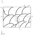
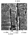
- FIG. 1 is an enlarged plan view showing a part of the surface of the decorative material 10.
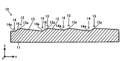
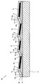
- FIG. 2 is a partial cross-sectional view of the decorative material 10.
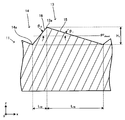
- FIG. 3 is an enlarged view of a part of FIG.
- FIG. 4 is a diagram illustrating ⁇ 1 and ⁇ 2 in the uneven pattern including the first inclined surface and the second inclined surface constituting the uneven pattern of the decorative material.
- FIG. 5 is a plan view illustrating the relationship between the surface roughness at the ridge line portion and the valley line portion.
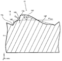
- FIG. 6 is a cross-sectional view for explaining the relationship between the surface roughness at the ridge line portion and the valley line portion.
- FIG. 7 is a diagram illustrating an example in which ⁇ 1 , ⁇ 2 , Ra 1 , and Ra 2 are measured.
- FIG. 1 is an enlarged plan view showing a part of the surface of the decorative material 10.
- FIG. 2 is a partial cross-sectional view of the decorative material 10.
- FIG. 3 is an enlarged view of a
- FIG. 8 is a cross-sectional view of the decorative material 20.
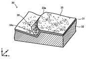
- FIG. 9 is a perspective view of a part of the decorative material 30.
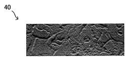
- FIG. 10 is a plan view of the decorative material 40.
- FIG. 11 is a perspective view of a part of the decorative material 40.
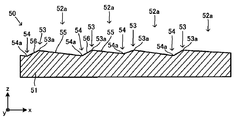
- FIG. 12 is an enlarged plan view showing a part of the surface of the decorative material 50.
- FIG. 13 is a cross-sectional view of the decorative material 50.
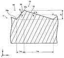
- FIG. 14 is an enlarged view of a part of FIG.
- FIG. 15 is a plan view of the decorative material 60.
- FIG. 16 is a cross-sectional view of a part of the decorative material 60.
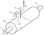
- FIG. 17 is a diagram illustrating a scene in which unevenness is formed on a mold by a laser.
- FIG. 18 is an example of the embossed plate, and is a plan view of a part of the embossed plate for producing the decorative material 40.
- FIG. 19 illustrates the layer structure of the decorative material 10 ′.
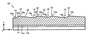
- FIG. 20 illustrates the layer structure of the decorative material 10 ′′.
- FIG. 1 is the figure (plan view) which expanded a part of cosmetic material 10 concerning a 1st form, and planarly viewed from the uneven
- FIG. 1 also shows arrows (x, y, z) representing directions, that is, coordinate systems.
- the xy direction is the in-plane direction of the decorative material 10
- the z direction is the thickness direction, that is, the normal direction of the in-plane direction (xy plane). Therefore, FIG. 1 is a view of the decorative material 10 viewed from the z direction (normal direction) which is the uneven pattern side.
- the decorative material 10 of this embodiment is provided with an uneven pattern on the surface of a wall coating processed with a pestle or the like using cement, wall soil, plaster or the like by a plasterer.
- FIG. 2 shows a cross section in the thickness direction of the decorative material 10 along the line indicated by II-II in FIG. 1 (that is, a surface cut along one surface parallel to the zx plane).
- This figure is a cross section cut in a straight line so as to cross the ridge line 13 a formed by the top of the convex portion 13 in the concave-convex shape of the substrate 11.
- Such a cross section may be referred to as a main cut surface.
- 3 is a part of FIG. 2 and an enlarged view focusing on the periphery of the ridge line 13a formed by the top of one convex portion 13 and the valley line 14a formed by the bottom of one concave portion 14. expressed.
- the decorative material 10 of the present embodiment has a concavo-convex shape in which the convex portion 13 and the concave portion 14 are repeated on the surface, and the ridge line 13 a and the concave portion 14 formed by the top of the convex portion 13.
- the valley line 14a formed by the valley bottom represents a three-dimensional relief pattern with a scarlet tone by the plasterer.
- the decorative material 10 has a base material 11, and has a concavo-convex pattern composed of convex portions 13 and concave portions 14 on the surface of one surface of the base material 11.
- a concavo-convex pattern composed of convex portions 13 and concave portions 14 on the surface of one surface of the base material 11.
- the base material 11 is a member having a function of imparting strength to the decorative material 10 while supporting an uneven pattern.
- the form of the substrate 11 may be any of a film, a sheet, or a plate.
- the film is called film, sheet, and plate in order from a relatively thin thickness.
- the difference depending on the thickness of the base material is not an essential matter but an important matter. Absent. Therefore, in the present specification, any of the terms film, sheet, and plate is appropriately replaced with other terms, and the essence of the present invention and the interpretation of the claims are unchanged.
- the base material 11 has only to have the same function as a conventionally known decorative material, the material is not particularly limited.
- the base material is usually polyethylene, polypropylene, olefinic thermoplastic elastomers, polyolefin resins such as ionomers, acrylic resins such as polymethyl methacrylate and polybutyl methacrylate, thermoplastics such as polyethylene terephthalate and polybutylene terephthalate.
- Polyester resin thermoplastic urethane resin, vinyl chloride resin, ABS resin (acrylonitrile-butadiene-styrene copolymer), thermoplastic resin such as styrene resin, melamine resin, unsaturated polyester resin, two-component curable urethane resin, epoxy resin
- thermosetting resins such as radical polymerization type acrylate type or cationic polymerization type epoxy type monomers and prepolymers, etc., which are cured with ionizing radiation (ultraviolet rays, electron beams, etc.) It is needed.
- ionizing radiation ultraviolet rays, electron beams, etc.
- paper, non-woven fabric, metal, wood and the like can be used by appropriately laminating with the above resin material in the form of a sheet, a plate, a three-dimensional object or the like.
- a paper sheet or a fibrous sheet such as a nonwoven fabric, a woven fabric, or a knitted fabric made of synthetic resin or glass fiber, melamine resin, phenol resin, urethane resin, epoxy resin, unsaturated polyester resin, diallyl phthalate
- a composite in which a thermosetting resin such as a resin is impregnated and cured can also be used.
- thickness of a base material in the case of a sheet-like base material or a film-like base material, thickness is 20 micrometers or more and about 1000 micrometers or less, for example, in the case of a plate-shaped base material, it is about 1 mm or more and about 20 mm or less. Things can be used.
- the concavo-convex pattern is formed by repeating the convex portions 13 and the concave portions 14.
- the convex portion 13 is formed by connecting one end of the first inclined surface 15 and one end of the second inclined surface 16 at the top, and this top forms the ridge line 13a.
- the recess 14 is formed by connecting the other end of the first inclined surface 15 and the other end of the second inclined surface 16 at a valley bottom, and this valley bottom forms a valley line 14a.
- the convex part 13 and the recessed part 14 are repeated alternately, and the ridgeline 13a and the trough line 14a are repeated alternately.
- the ridgeline 13a and the valley line 14a extend as shown in FIG.
- the first inclined surface 15 is a sheet surface in-plane direction on the sheet surface P Sheet (P 2 Sheet shown in FIG. 3), that is, the xy plane in FIG. 2 and FIG. And an inclination angle of ⁇ 1 with respect to a direction parallel to a virtual plane parallel to the axis.
- the second inclined surface 16 has an inclination angle of ⁇ 2 with respect to a direction parallel to the in-sheet direction in the sheet surface P Sheet .
- a cross section in the sheet plane direction is indicated by a dotted line extending in parallel to the x direction.
- the angle between the seat surface P Sheet and the first inclined surface 15 it is referred to as a tilt angle theta 1 or abbreviated inclination angle theta 1 with the first inclined surface 15.
- an angle formed between the sheet surface P Sheet and the second inclined surface 16 is referred to as an inclination angle ⁇ 2 of the second inclined surface 16 or an inclination angle ⁇ 2 for short.
- the inclination angle ⁇ 1 and the inclination angle ⁇ 2 may be collectively referred to as an inclination angle or inclination angles ⁇ 1 and ⁇ 2 .
- sheet surface P Sheet refers to a surface that represents a direction extending (expanding) in a plane when the cosmetic material is viewed as a whole.
- the surface obtained by smoothing the envelope surface of the surface of the concavo-convex pattern by the least square method or the like is often a flat surface.
- a plane obtained by smoothing the envelope surface and an arbitrary plane parallel to the plane correspond to the sheet surface.
- the surface opposite to the uneven pattern of the decorative material is smoothed and any arbitrary parallel to this surface.
- the surface can be a sheet surface.
- the envelope surface once smoothed or the opposite surface once smoothed is further added.
- the surface planarized by the least square method or the like is defined as the sheet surface.
- the sheet surface P Sheet serving as a measurement standard for defining the inclination angle a sheet surface that intersects both the first inclined surface 15 and the second inclined surface 16 is selected. Among them, the difference in inclination angle between the first inclined surface 15 and the second inclined surface 16 has the largest influence on the visual and tactile sensation in the vicinity of the ridge line 13a (top), and therefore the inclination angle ⁇ 1 and the inclination angle ⁇ 2.
- a surface close to the ridge line 13a can be selected. Considering this point, the sheet surface P Sheet to be used as the measurement standard for the inclination angle is selected as in the following (1) to (6), and the inclination angle ⁇ 1 and the inclination angle ⁇ 2 are obtained.
- P 2 Sheet is a sheet surface that intersects the two sides of the first inclined surface 15 and the second inclined surface 16 as represented by P 2 Sheet 3 based on the revealed the above magnitude relationship. Specifically, this is done as follows.
- the triangular prism formed of the first inclined surface 15, the second inclined surface 16, and the specific sheet surface P 2 Sheet is the triangular prism on the main cutting plane of the ridge line 13a (in the drawing, the zx plane or a plane parallel thereto). And a triangle formed by intersecting the orthogonal plane.
- An internal angle formed by a base corresponding to the specific sheet surface P 2 Sheet in the triangle and a side corresponding to the first inclined surface 15 is defined as an inclination angle ⁇ 1 of the first inclined surface 15.
- an inner angle formed by a base corresponding to the specific sheet surface P 2 Sheet in the triangle and a side corresponding to the second inclined surface 16 is defined as an inclination angle ⁇ 2 of the second inclined surface 16.
- a surface obtained by smoothing the first inclined surface 15 is referred to as a smoothed first inclined surface 15S
- a surface obtained by smoothing the second inclined surface 16 is referred to as a smoothed first inclined surface 16S.
- the smoothed first inclined surface 15S and the smoothed second inclined surface 16S Based on the properties of the smoothed first inclined surface 15S and the smoothed second inclined surface 16S, the following is considered.
- the smoothed first inclined surface 15S or the smoothed first inclined surface 16S is a non-planar surface such as a curved surface
- the following is performed.
- the ridge line 13a (a point (vertex) corresponding to) and a trough line 14a (a point corresponding to) are formed as shown in FIG. Connect and determine a plane perpendicular to the main cutting plane. In the main cutting plane as shown in FIG. 4, this corresponds to drawing a straight line connecting a point corresponding to the ridge line 13a and a point corresponding to the valley line 14a.
- planarized smoothed first inclined surface 15P and a planarized second smoothed inclined surface 16P This is referred to as a planarized smoothed first inclined surface 15P and a planarized second smoothed inclined surface 16P.
- the smoothed first inclined surface 15S or the smoothed second inclined surface 16S that is non-planar is replaced with the smoothed first inclined surface 15P or the flattened second smoothed inclined surface 16P.
- the inclination angle ⁇ 1 or the inclination angle ⁇ 2 is obtained by the same method as in the case where the inclined surface is a plane.
- the uneven pattern drives out value of the inclination angle theta 1 and the inclination angle theta 2 may be the inclination angle theta 1 and the inclination angle theta 2 represent.
- the specific sheet surface P 2 Sheet to be used as the measurement standard for the tilt angle definition is selected, and the tilt angle ⁇ 1 and the tilt angle ⁇ 2 are obtained.
- ⁇ 1 is configured to have a smaller relationship than ⁇ 2 .
- inclination-angle (theta) 1 can be larger than 0 degree and 10 degrees or less.
- the inclination angle theta 2 may be less 80 ° larger than 10 °.
- the difference between the inclination angle ⁇ 1 and the inclination angle ⁇ 2 is not particularly limited, but the larger one is more effective from the viewpoint of visual and tactile sensation. The difference can be 5 ° or more and 70 ° or less.
- the interval between the adjacent convex portions 13 (corresponding to the sum (L 15 + L 16 ) of the length of the orthogonal projection of the inclined surface 15 and the inclined surface 16 in FIG. 3 with respect to the sheet surface P sheet (P 2 sheet )) is Since it differs depending on the pattern to be expressed, there is no particularly preferable range, and the size necessary for expression can be set as appropriate, and it may be regular or irregular. However, from the viewpoint of reproducing the appearance of an ordinary crease-like and stone-like concavo-convex pattern, the interval between the convex portions 13 can be in the range of 5 mm to 200 mm.
- a large difference in height can be obtained in terms of sufficient visibility of the pattern formed on the decorative material, appearance of the design, and reproducibility of the touch.
- the height difference can be reduced from the viewpoint of ease of forming the uneven pattern on the substrate 11. That is, in general, as the height difference increases, it becomes more difficult to manufacture the plate and faithfully shape the uneven pattern of the plate to the base material.
- the minimum thickness of the base material which can shape a concavo-convex pattern also increases. Therefore, it is possible to set the viewpoint of compatibility between the reproducibility and ease of shaping the design appearance, the height difference H 1 to the extent more than 1000 ⁇ m or less 1 [mu] m.
- the fan-like finish by the scars by the plasterer is exemplified as the uneven pattern.
- the so-called surface uneven pattern formed on the surface of the finished surface of cement, plaster, wall soil, etc. is simulated by plastering work represented by uneven patterns such as stucco-like, wave finishing, fan finishing, etc.
- uneven patterns such as stucco-like, wave finishing, fan finishing, etc.
- the uneven surface pattern of the cleavage surface of the polycrystalline stone plate such as granite
- the uneven surface pattern of the stone fracture surface of the surface of various stone plates such as limestone, marble (crystalline limestone), sandstone, etc.
- the concavo-convex pattern expressed in the present invention does not necessarily have the same concavo-convex shape or concavo-convex structure as the actual concavo-convex pattern. In short, in the present invention, it is only necessary that the observer can perceive the design appearance and / or tactile sensation similar to the uneven pattern to be expressed.
- FIG. 5 and FIG. 6 show diagrams for explanation.
- FIG. 5 is an enlarged plan view showing the range indicated by V in FIG. 1
- FIG. 6 is a sectional view from the same viewpoint as FIG.
- a in FIG. 5 and FIG. 6 the surface roughness Ra in a linear range of a predetermined length in the direction along the ridge line 13 a in the portion near the ridge line 13 a in the first inclined surface 15 in the uneven pattern.
- Ra 1 is assumed.
- the valley line is formed on the first inclined surface 15 at a portion near the valley line 14 a across the edge line 13 a close to A and the valley line 14 a adjacent thereto in the uneven pattern.
- the ridge line side is preferably a relatively rough surface rather than the valley side (near the valley line 14a).
- an effective and rich expression can be made when expressing the appearance and tactile sensation of the scratched surface uneven pattern of plastering work or the cleaved surface of the polycrystalline stone plate surface.
- the surface roughnesses Ra 1 and Ra 2 are measured as follows. As in the case of the inclination angle theta 2 of the first inclined surface 15 inclined angle theta 1 and the second inclined surface 16 of the, degree of influence of the difference in surface roughness on the visual and tactile sensation ridge 13a (top) is the largest near Therefore, the position of the measurement reference surface roughness Ra 1 and Ra 2 are preferably chosen surface near the ridge line 13a. However, the influence on the visual and tactile sensations is slightly different between the inclination angle and the surface roughness. Considering this point, the measurement positions and measurement conditions for the surface roughness Ra 1 and Ra 2 are selected as follows.
- the surface roughness Ra ( ⁇ m) means the arithmetic average roughness in JIS B 0601-2001.
- the surface roughness Ra 1 near the ridge line 13a of the first inclined surface 15 has a distance (L A ) within 2 mm on the first inclined surface 15 from the ridge line 13a. the straight line in the area to the measured length L C 4 mm, a value measured at 0.8mm cutoff value.
- the measured length L D 4 mm a value measured at 0.8mm cutoff value.
- the distance from the edge line 13a (L A) is, ( 1/2) ⁇ L short or less, more preferably, (1/4) in a straight line in the following areas ⁇ L short, 4 mm measurement length L C, a value measured at 0.8mm cutoff value .
- the distance (L B ) from the valley line 14 a is (1 ⁇ 2) ⁇ L short on the first inclined surface 15. or less, more preferably, (1/4) in a straight line in the following areas ⁇ L short, 4 mm measured length L D, a value measured at 0.8mm cutoff value.
- Ra 1 and Ra 2 are not particularly limited, Ra 1 may be less 20 ⁇ m or 0.02 [mu] m.
- Ra 2 can be set to 0.005 ⁇ m or more and 5 ⁇ m or less.
- the difference between Ra 1 and Ra 2 is not particularly limited, but the larger one is more effective from the viewpoint of visual and tactile sensations.
- the difference can be 0.02 ⁇ m or more, 0.5 ⁇ m or more, and further 5 ⁇ m or more.
- theta 2 of the inclination angle theta 1 and the second inclined surface of the first inclined surface for decorative material was produced. Further, the surface roughness was measured Ra 2 of the surface roughness Ra 1 and valley portions of the ridge portion.
- FIG. 7 the figure which expanded a part among the top views of the cosmetics made into the measuring object was represented. Among these, the part enclosed by P and Q was made into the measuring object.
- the cosmetic material produced for the measurement was a single layer base material made of a white polyvinyl chloride sheet having a thickness of 300 ⁇ m and a plasticizer part of 20 parts by mass added with a white pigment made of titanium dioxide particles. is there. This is formed by forming the concavo-convex pattern having the features of the concavo-convex shape shown in Table 1 on the surface of one side thereof as shown in FIG.
- ⁇ Measurement of ⁇ 1 and ⁇ 2 > ⁇ 1 and ⁇ 2 were measured according to the method described above by inputting a three-dimensional shape with a three-dimensional measuring device (Keyence Corporation, VR-3000).
- a cosmetic material in this manner could be obtained.
- the cosmetic material has a different texture from the viewpoint of visual and tactile sensations.
- FIG. 8 shows a diagram for explaining the decorative material 20 of the second form.
- FIG. 8 is a view from the same viewpoint as FIG.
- symbol is attached
- the pattern forming layer 12 is a layer that is laminated on one surface of the base material 11 and imparts a pattern to the decorative material. In this embodiment, the pattern forming layer 12 has a predetermined uneven shape to form an uneven pattern.
- the concavo-convex pattern is directly formed on the base material 11 without providing the pattern forming layer 12 separately from the base material 11.
- a pattern forming pattern can be adopted.
- the pattern layer 21 is a layer on which a pattern (design) is applied, and is laminated on the first inclined surface 15 in this embodiment.
- the concrete pattern in the pattern layer 21 is a grain pattern represented by wood grain, stucco, fan finish, etc., cleaved surface of a rock plate such as granite, marble, sandstone, etc.
- Various patterns such as tones, color patterns, photographs, paintings, drawings or geometric patterns, fabrics typified by various fabrics and non-woven fabrics, genuine leather, artificial leather, wrinkle resins, etc. be able to. For example, if a pattern with a predetermined expression (in the present embodiment, a scarlet tone) is formed by the pattern forming layer 12, a pattern matched to this pattern can be obtained.
- corrugation of the pattern formation layer 12 may be sufficient, and the pattern different from the unevenness
- Such a design of the pattern layer 21 can be formed by an ink layer formed by printing such as gravure printing, silk screen printing, and ink jet printing.
- ink which comprises the pattern layer 21 according to the color tone of a pattern and the required physical property from well-known things.
- the ink binder resin for example, an acrylic resin, a vinyl chloride-vinyl acetate copolymer, a cellulose resin, a urethane resin, a polyester resin, or the like can be used alone or in combination of two or more.
- colorants include white colorants such as titanium white and zinc white, black colorants such as carbon black (black), iron black, and azomethine azo pigments, yellow lead, titanium yellow, and polyazo.
- Yellow colorants such as yellow, isoindolinone yellow, nickel azo complex, red colorants such as petals, cadmium red, polyazo red, quinacridone red, blue colorants such as ultramarine, cobalt blue, phthalocyanine blue, aluminum, brass, etc.
- a colorant such as a metallic pigment comprising a flake-like foil piece, a pearlescent pigment comprising a scaly foil piece such as titanium dioxide-coated mica and basic lead carbonate can be used.
- an appropriate amount of various additives such as a plasticizer, a surfactant, a heat stabilizer, an ultraviolet absorber, a light stabilizer, and a lubricant can be added as necessary.
- the transparent protective layer 22 is a layer that protects the pattern layer 21 and the pattern forming layer 12 from contamination, scratches, and the like, and can be made of a transparent resin, transparent glass, or the like.
- a transparent resin for example, a layer made of a thermoplastic resin or a cured resin can be exemplified. Note that the transparent protective layer 22 is omitted when the substrate 11, the pattern forming layer 12, and the pattern layer 21 alone can ensure sufficient surface durability such as contamination resistance and scratch resistance in the intended application. be able to.
- thermoplastic resin examples include acrylic resins such as polymethyl (meth) acrylate and polyethyl (meth) acrylate, polyolefin resins such as polypropylene and polyethylene, fluorine resins such as polyvinyl fluoride and polyvinylidene fluoride, polyethylene terephthalate ( PET), polyester resins such as polybutylene terephthalate (PBT), polyethylene naphthalate (PEN), polycarbonate resin, vinyl chloride resin, acrylonitrile-butadiene-styrene resin (ABS resin), acrylonitrile-styrene-acrylic ester resin, etc. Can be mentioned. Note that “(meth) acryl” means acrylic or methacrylic.
- the layer made of curable resin is a layer obtained by curing the curable resin composition, and the curable resin composition is a composition containing a curable resin.
- the curable resin composition include a thermosetting resin composition containing a thermosetting resin, an ionizing radiation curable resin composition containing an ionizing radiation curable resin, and the like.
- the thermosetting resin include unsaturated polyester resin, polyurethane resin (including two-component curable polyurethane), epoxy resin, amino alkyd resin, phenol resin, urea resin, diallyl phthalate resin, melamine resin, guanamine resin, Examples include melamine-urea cocondensation resin, silicon resin, polysiloxane resin, and the like.
- thermosetting resin composition contains components involved in the curing reaction of the thermosetting resin, for example, a catalyst, a curing agent (including a crosslinking agent, a polymerization initiator, a polymerization accelerator, etc.) and the like as necessary. May be.
- An ionizing radiation curable resin is a resin that undergoes a crosslinking polymerization reaction upon irradiation with ionizing radiation and changes to a three-dimensional polymer structure. Ionizing radiation has energy quanta that can polymerize or crosslink among electromagnetic waves and charged particle beams.
- UV and electron beams (EB) electromagnetic waves such as X-rays and ⁇ -rays, ⁇
- UV ultraviolet rays
- EB electron beams
- the electron beam curable resin can be made solvent-free, does not require a photopolymerization initiator, and provides stable curing characteristics.
- the ionizing radiation curable resin include one type of monomers, oligomers, prepolymers, etc. having polymerizable unsaturated bonds such as (meth) acryloyl groups that can be cross-linked by irradiation of ionizing radiation, epoxy groups, etc. in the molecule.
- a composition containing the above can be used.
- the thickness of the transparent protective layer 22 is not particularly limited, but can be 0.1 ⁇ m or more and 20 ⁇ m or less. If it is thin, durability due to bending is high, but scratch resistance is weak, and if it is thick, it is strong against scratches and scratches, but weak against deformation such as bending, and cracks occur.
- the transparent protective layer 22 can be used. For example, it can be 1 ⁇ m or more and 10 ⁇ m or less.
- the cosmetic material 20 as described above has an effect similar to that of the cosmetic material 10 by providing the relationship in which the inclination angle ⁇ 1 is smaller than the inclination angle ⁇ 2 .
- FIG. 9 shows a diagram for explaining the decorative material 30 according to the third embodiment.
- FIG. 9 is a perspective view in which a part of the ridge line 33a and the valley line 34a is partially cut out from the decorative material 30.
- the decorative material 30 of this embodiment has a pattern forming layer 32 having a stone-like pattern.
- the pattern forming layer 32 also has a stone tone in the direction in which the ridge line 33a and the valley line 34a extend, following the pattern formation layer 12.
- the pattern forming layer 32 also has a first inclined surface 35 and a second inclined surface 36 following the pattern forming layer 12 to form a ridge line 33a and a valley line 34a, and the inclination angle of the first inclined surface 35 is the second angle.
- the relationship between the surface roughness in the vicinity of the ridge line 33a and the surface roughness in the vicinity of the valley line 34a is also formed so that the surface roughness in the vicinity of the ridge line is larger than the surface roughness in the vicinity of the valley line, following the pattern forming layer. May be.
- a monotonous expression is avoided, and a cosmetic material having a rich appearance and less discomfort close to the actual texture can be obtained.
- it is a different cosmetic material from the viewpoint of tactile sensation.
- the pattern forming layer 32 also serves as a base material, and a pattern layer 31 that expresses the design appearance of the wall surface using colored plaster made of colored ink on one surface of the single pattern forming layer 32.
- the transparent protective layer is omitted.
- the pattern of the pattern layer is a stone-tone pattern composed of a colored ink layer having a design appearance that matches the pattern of irregularities of a scarlet tone and having a color gradation distributed in the plane. Applied.
- the uneven pattern of the pattern forming layer 32 and the pattern of the pattern layer may be different.
- FIGS. 10 and 11 are views for explaining the decorative material 40 according to the fourth embodiment.
- FIG. 10 is a plan view of the decorative material 40 corresponding to FIG. 1
- FIG. 11 is a perspective view showing a part of the decorative material 40.
- the decorative material 40 of this embodiment is an example having a stone-like uneven pattern on one surface of the substrate 11.
- the concavo-convex pattern is used to represent the texture of the concavo-convex pattern of the decorative material 10 in the direction in which the ridge line 43a and the valley line 44a extend.
- the first inclined surface 45 and the second inclined surface 46 are formed to follow the concavo-convex pattern of the decorative material 10 to form a ridge line 43 a and a valley line 44 a, and the first inclined surface 45 is inclined. It has an uneven shape so that the angle is smaller than the inclination angle of the second inclined surface 46. Further, the relationship between the surface roughness in the vicinity of the ridge line 43a and the surface roughness in the vicinity of the valley line 44a follows the uneven pattern of the decorative material 10, so that the surface roughness in the vicinity of the ridge line is larger than the surface roughness in the vicinity of the valley line. You may form in.
- a concavo-convex pattern is formed on one surface of the base material 11, and a pattern (not shown) that expresses a design outer wall of the wall surface using colored plaster made of colored ink on one surface of the concavo-convex pattern
- the transparent protective layer is omitted.
- FIG. 12 is an enlarged view of a part of the decorative material 50 according to the fifth embodiment, and is a plan view (plan view) from the uneven pattern side.
- the decorative material 50 of the present embodiment is a decorative material having a grainy tone, and among them, a surface irregularity pattern of a granite cleaved surface tone.
- FIG. 13 shows a cross section in the thickness direction of the decorative material 50 along the line indicated by XII-XII in FIG. 12 (that is, a surface cut along one surface parallel to the zx plane).
- This figure is a figure corresponding to FIG. 2, which is a cross-section cut in a straight line so as to cross the ridge line 53 a formed by the top of the convex part 53 in the concavo-convex shape of the base material 51, and is a main cut surface.
- FIG. 13 is a conceptual diagram, and does not accurately represent the XII-XII cross section.
- FIG. 14 is a part of FIG.
- FIG. 4 is a diagram corresponding to FIG. 3.
- a plurality of regions 52a are arranged in the xy in-plane direction so as to include a closed region 52a in plan view, and the convex portion 53 and the concave portion 54 are formed on the surface thereof.
- the ridgeline 53a which the top part of the convex part 53 forms, and the trough line 54a which the trough bottom of the recessed part 54 forms are comprised, and the ridgeline 53a forms the outline of the area
- the decorative material 50 includes a base material 51, and has a concavo-convex pattern including a convex portion 53 and a concave portion 54 on the surface of one surface of the base material 51.
- the base material 51 can be considered in the same manner as the base material 11 described above.
- the concavo-convex pattern is formed by repeating convex portions 53 and concave portions 54.
- the convex portion 53 is formed by connecting one end of the first inclined surface 55 and one end of the second inclined surface 56 at the top portion, and the top portion forms a ridge line 53a.
- the recess 54 is formed by connecting the other end of the first inclined surface 15 and the other end of the second inclined surface 56 at the bottom of the valley, and this valley bottom forms a valley line 54a.
- the convex part 53 and the recessed part 54 are repeated alternately, and the ridgeline 53a and the trough line 54a are repeated alternately.
- the ridge line 53a and the valley line 54a extend to form a closed region 52a as shown in FIG.
- a plurality of regions 52a are included in the xy plane as shown in FIG.
- the inclination angle ⁇ 1 and the inclination angle ⁇ 2 shown in FIG. 14 can be considered in the same manner as in the description of the decorative material 10.
- ⁇ 1 is smaller than ⁇ 2 .
- the interval between the adjacent regions 52a varies depending on the tone of the stone to be expressed, so there is no particularly preferable range thereof, and the size necessary for the expression can be set as appropriate. There may be. However, from the viewpoint of reproducing the appearance of a normal stone-patterned concavo-convex pattern, the interval between adjacent regions 52a can be set in a range of 5 mm to 200 mm.
- the height difference in terms of sufficient visibility of the pattern formed on the decorative material, appearance of the design, and reproducibility of the tactile sensation, the height difference can be generally increased.
- the height difference is reduced from the viewpoint of ease of forming the uneven pattern on the base material 51. That is, in general, as the height difference increases, it becomes difficult to manufacture a plate and to faithfully shape a plate with a concavo-convex pattern. And the minimum thickness of the base material which can shape a concavo-convex pattern also increases. Therefore, from the viewpoint of achieving both the reproducibility of the design appearance and the ease of shaping, this difference can be about 1 ⁇ m to 1000 ⁇ m.
- uneven pattern expressed here does not necessarily have the same uneven shape or uneven structure as the actual uneven pattern. In short, it is only necessary that the observer can perceive the design appearance and / or tactile sensation similar to the uneven pattern to be expressed.
- the decorative material 50 of the present embodiment adopts the form described with reference to FIG. 8 and may be provided with a pattern forming layer, a picture layer, and a transparent protective layer.
- FIGS. 15 and 16 are views for explaining the decorative material 60 according to the sixth embodiment.
- FIG. 6 is a plan view corresponding to FIG.
- FIG. 16 shows a cross-sectional view in which one region 52a focuses on the region 52a having the ridges 61.
- the decorative material 60 of the present embodiment has a plurality of line-shaped ridges 61 arranged in a partial region 52 a.
- parts that can be considered in the same manner as the decorative material 50 are denoted by the same reference numerals as those of the decorative material 50.
- the ridges 61 have a predetermined cross section (in the present embodiment, a rectangular cross section) and extend in one direction within the region 52a, and a plurality of the ridges 61 are arranged at intervals in the region 52a in a direction different from the extending direction. .
- the ridge 61 is formed on the first inclined surface 55 having a small inclination.
- the present invention is not limited to this, and the ridges 61 may be arranged only in the second inclined surface 56 or in both directions of the first inclined surface 55 and the second inclined surface 56.
- the region 52a in which the ridges 61 are arranged and the region 52a in which the ridges 61 are not arranged are mixed, but not limited to this, even if the ridges 61 are arranged in all the regions 52a. Good.
- the protrusions 61 arranged in the plurality of regions 52a are not necessarily required to have the same height, pitch, width, and extending direction, and at least any one of the regions 52a is different. You can also Even with such a decorative material 60, in addition to the above-described effects, it is possible to make a different visual sense and touch feel.
- the manufacturing method described below includes a step of producing a block image, a step of producing a plate, and a step of forming an uneven pattern.
- a pattern in plan view to be expressed on the surface of the substrate 11 is acquired as an image density (light / dark), and this is used as the block image.
- the artwork image is preferably digital data, if it is not digital data, it can be obtained by using a scanner to read the original document such as a stone, surface of a plastered finish, etc. or a photograph of the original document with a scanner. Pixels are arranged in a two-dimensional coordinate plane (x, y), and digital data in which each pixel has a unique density value is obtained. Further, when a pattern is designed from the beginning using digital data using CAD or the like, the digital data can be used. Thus, a block image is obtained as digital data.
- a linear binary image pattern is generated in the continuous tone density image based on the obtained continuous tone image having the pattern density.
- Some of the pixels become pixels constituting a ridge line or a valley line, and a ridge line and a valley line in the block image are obtained as digital data.
- the present invention is not limited only to the decorative material obtained by the following method. That is, the rate of change in image density is calculated as the position coordinates increase in each direction within the plane.
- the pixel at the maximum point where the image density changes from increasing to decreasing as the coordinates increase is defined as the pixel of the ridge line 13a.
- the pixel of the minimum point where the image density is changed from the decrease to the increase with the increase of the coordinates is set as the pixel of the valley line 14a.
- the density value gradually increases toward the point corresponding to the ridge line 13a in the direction orthogonal to the line corresponding to the ridge line 13a in the two-dimensional coordinate plane, and the point corresponding to the ridge line 13a.
- the image data has a feature that the density value becomes maximum and gradually decreases from the point corresponding to the ridge line 13a.
- the density value gradually decreases toward the point corresponding to the valley line 14a in the direction orthogonal to the line corresponding to the valley line 14a in the two-dimensional coordinate plane, and the valley line 14a.
- the image data has a feature that the density value becomes minimum at a point corresponding to, and the density value gradually increases as the point gradually departs from the point corresponding to the valley line 14a.
- the uneven pattern of obtaining the decorative material to be manufactured the inclination angle theta 2 of the inclination angle of the first inclined surface 15 theta 1 and the angle between the second inclined surface 16 the second inclined surface 16, "theta 1 is theta
- the design value of “area ratio ⁇ with respect to the total area of the decorative material having an area satisfying the relationship smaller than 2 ” is set to a desired value.
- the difference in density gradient before and after the ridge line 13a is calculated, and the difference in average density gradient in the regions on both sides sandwiching the ridge line 13a is confirmed.
- the density value at each position coordinate is obtained while gradually advancing a predetermined distance toward the ridge line 13a in a direction orthogonal to the ridge line 13a, and an average density gradient along the advanced path and distance is calculated.
- the predetermined distance is a distance from the adjacent valley line 14a to the ridge line 13a when the valley line 14a and the ridge line 13a are adjacent to each other.
- the density value at each position coordinate is obtained while moving forward from the ridge line 13a toward the adjacent valley line 14a along the forward path, and the average density gradient along the forward path and distance is calculated.
- the length of the portion of the ridge line 13a that satisfies the condition that the average density gradient on both sides of the ridge line 13a is different among the pixels on the entire ridge line 13a is set to the entire region of the continuous tone density image.
- An integral value S integrated over the whole is obtained.
- the integrated value S is compared with the area ratio ⁇ set as the design value. And whether or not the error of both has converged within a preset allowable range e, that is,
- ⁇ e Check whether the condition is satisfied. If this has converged, the composition image creation is terminated. On the other hand, if it does not converge, the density of each pixel in the continuous tone density image is adjusted so that it converges.
- the ridge line generated in this way corresponds to the ridge line in the decorative material, and the area up to the adjacent valley line on one side selected by the image forming image creator with the ridge line as a reference. Is assigned to the first inclined surface, and the region up to the adjacent valley line on the other side is assigned to the second inclined surface.
- the uneven pattern of the reverse unevenness of the uneven pattern formed by converting the grayscale image (darkness of density value) in the plan view shape pattern into the plate depth based on the image under the plate
- An embossed plate (molding die for decorative material) on the surface is prepared.
- the manufacturing process of the concavo-convex pattern includes the following procedures (A) to (E).
- a metal roll 70 for embossing engraving as shown in FIG. 17 is prepared.
- the metal roll 70 is obtained by plating a copper layer on the surface of a hollow iron cylinder having rotational drive shafts (shafts) 71 at both ends in the axial direction.
- the surface of the metal roll 70 is polished and roughened with a grindstone, and a process for preventing a decrease in engraving efficiency due to mirror reflection of the engraving laser beam is performed.
- a laser beam direct engraving machine is used to engrave the surface of the metal roll 70 prepared in step (B) based on the uneven pattern image data created in step (A).
- a concave-convex shape having the same planar view shape as the concave-convex pattern on the surface of the decorative material as shown in FIG. . Therefore, the shape to be provided in the uneven pattern in the embossed plate is an aspect in which the uneven relation of the uneven pattern in the decorative material described above is reversed, and can be considered in the same manner.
- the metal roll 70 is driven by an electric motor through the rotation drive shaft 71 and rotates around the rotation drive shaft 71 as a central axis.
- the entire surface of the metal roll 70 is scanned with fiber laser light L having an oscillation wavelength of 1024 nm, a laser spot diameter of 10 ⁇ m, and an output of 600 W emitted from the laser head 72.
- the laser light is switched ON / OFF (irradiation or non-irradiation switching) according to the density value of the concavo-convex pattern image data created in the step (A), and the irradiation position is obtained by a single laser light irradiation.
- a recess having a depth of 10 ⁇ m is formed by evaporation of the metal.
- the scanning with respect to the metal roll surface by such laser light is repeated 10 times. Further, in order to prevent the evaporated metal from becoming a powder and remaining or adhering to the surface of the metal roll 70, the engraving liquid T was sprayed from the engraving liquid discharge port 73 to the laser light irradiation region on the surface of the metal roll 70. Laser light irradiation is performed in the state. At that time, for example, in the position coordinates of the image density corresponding to the plate depth of 50 ⁇ m on the concavo-convex pattern image data, the laser beam is irradiated (ON) only for the first five out of a total of 10 scans, and the remaining 5 The batch is controlled so that the laser beam is not irradiated (OFF).
- the engraving control program of the laser beam direct engraving machine is set so that the distribution width of the image density on the uneven pattern image data corresponds to the distribution width of the plate depth.
- the maximum density is set to the maximum plate depth (maximum engraving amount) and the minimum Program the density to correspond to the minimum plate depth (minimum engraving amount).
- the scanning of the laser beam is completed, and a desired uneven shape is formed on the surface of the metal roll 70.
- FIG. 18 shows a plan view of a part of the embossed plate thus obtained.
- This embossed plate is an embossed plate for molding the decorative material 40 described above.
- the decorative material 10 is obtained by embossing the base material 11 using the produced plate (embossed plate).
- the embossing may be performed by an appropriate known method and is not particularly limited.
- a typical embossing method is, for example, as follows.
- a resin sheet made of a thermoplastic resin such as a polyolefin resin is used as the substrate.
- the substrate is heated and softened, and an embossed plate is pressed on the surface thereof to form an uneven pattern on the surface of the resin sheet on the surface of the resin sheet.
- the resin sheet is cooled and solidified to fix the uneven pattern on the resin sheet.
- the resin sheet with the uneven pattern is released from the embossed plate.
- the various embossing methods will be further described. For example, there are the following methods (a) to (e).
- a resin sheet to be a base material is heated and softened, and an embossed plate is pressed and embossed.
- B Embossing and laminating by heat-sealing a resin sheet (base material) to be a surface sheet and a resin sheet (second base material) to be a base sheet by hot pressure when pressing the embossing plate Are embossed by the doubling embossing method.
- C A resin sheet (base material) to be used as a surface sheet is melt-extruded from a T-die and brought into contact with a cylindrical embossing plate that also serves as a cooling roller, and embossed simultaneously with the formation of the surface sheet.
- a resin sheet (second base material) serving as a base sheet inserted further on the back surface side of the top sheet is thermally fused to perform doubling embossing simultaneously with film formation.
- an uncured liquid material of ionizing radiation curable resin is applied to the surface of a cylindrical embossed plate. Furthermore, an uncured liquid material is cured by irradiating with ionizing radiation in a state where a base sheet made of a resin sheet or the like is stacked thereon to obtain a cured product.
- An impregnated paper obtained by impregnating a paper such as titanium paper with an uncured material of a thermosetting resin such as a melamine resin is placed on a backing material such as a core paper or a wood plywood.
- the layers are laminated and integrated by hot press molding the layers to produce a thermosetting resin decorative material.
- an embossed plate is inserted on the surface of the impregnated paper, and when the thermosetting resin is impregnated and cured to make a decorative material, the surface is embossed simultaneously with the hot press.
- the base material used in the embossing methods (a) to (c) is typically a thermoplastic resin, and the base material used in the embossing method (d) is representative.
- An ionizing radiation curable resin is used, and a thermosetting resin is typically used as the base material used in the embossing method of (e).
- the cosmetic material 10 can be obtained as described above.
- 19 and 20 show the layer structure. These modified examples are modified examples based on the decorative material 10, but can be similarly applied to the other decorative materials described above.
- the decorative material 10 ′ has a configuration in which a decorative layer 11 a is formed on the back side of the base material 11.
- a transparent resin sheet is used as the base material 11 so that the decorative layer 11 a can be seen through, and the decorative layer is formed on the back surface of the base material 11.
- embossing may be performed by softening by heating and pressing the embossed plate on the front side.
- the decorative material 10 '' having the configuration shown in FIG. 20 has another base material 11b having a base sheet on the opposite side of the surface of the decorative layer 11a from the side on which the concavo-convex pattern is arranged.
- the decorative layer 11a is printed on the surface of the base 11b made of a colored opaque thermoplastic resin sheet as a base sheet, What is necessary is just to emboss a desired uneven
- the use of the decorative material described above is not particularly limited.
- interior materials for buildings such as walls, floors, and ceilings, exterior walls of buildings, roofs, gates, fences, fences, and other exterior materials, doors, windows Frames, door frames and other fittings, surrounding materials, surface materials for construction members such as baseboards, handrails, television receivers, refrigerators and other household appliances and copiers, etc.
- Surface materials of containers, surface materials of containers such as boxes and resin bottles, interior materials or exterior materials of vehicles, and interior materials or exterior materials of ships.
Landscapes
- Engineering & Computer Science (AREA)
- Textile Engineering (AREA)
- Architecture (AREA)
- Civil Engineering (AREA)
- Structural Engineering (AREA)
- Life Sciences & Earth Sciences (AREA)
- Wood Science & Technology (AREA)
- Finishing Walls (AREA)
Abstract
基材と、基材の一方の面に形成された凹凸模様と、を有し、凹凸模様を形成する凸部が、第一傾斜面と第二傾斜面とを有し、第一傾斜面の一端と第二傾斜面の一端とが連結することにより、凸部の頂部が稜線を成し、第一傾斜面とシート面とのなす傾斜角が、第二傾斜面とシート面との成す傾斜角よりも小さい前記凹凸模様を含む、化粧材。
Description
本発明は化粧材に関する。
化粧材における意匠表現は多岐に亘るが、例えば特許文献1乃至特許文献3のように、表面に石材の劈開面を模して表現したいわゆる石目調の模様や、セメントや石膏等の左官による鏝痕の壁面形状の凹凸模様が表現された化粧材がある。
化粧材の分野では、近年における嗜好の多様化や、よりリアルであったり、新しい視覚的、触感的な表面形態であったりする要求があり、かかる観点からより付加価値の高い意匠外観及び触感を発現する化粧材を提供することが望まれている。
そこで本発明は、これまでとは異なる質感を与え付加価値を高めることができる構造を具備した化粧材を提供することを課題とする。
発明者は、従来における石材の劈開面、セメントや石膏等の左官による壁面形状(鏝痕等)の表面凹凸を模した化粧材を検討した結果、その凹凸形状における高さの階調が、例えば、高低の2階調のみであったり、傾斜面があっても傾斜角が1種類のみであったり等であるため単調となっているという知見を得た。この知見に基づいて、視覚的、触感的にこれまでとは異なる模様の形態を具体化して本発明を完成させた。以下、本発明について説明する。
1つの態様は、表面に凹凸模様が形成されてなる化粧材であって、基材と、基材の一方の面に形成された凹凸模様と、を有し、凹凸模様を形成する凸部が、第一傾斜面と第二傾斜面とを有し、第一傾斜面の一端と第二傾斜面の一端とが連結することにより、凸部の頂部が稜線を成し、第一傾斜面とシート面とのなす傾斜角が、第二傾斜面とシート面との成す傾斜角よりも小さい凹凸模様を含む、化粧材である。
稜線部分における第一傾斜面の表面粗さが、稜線に隣接する凹部の谷線部分における第一傾斜面の表面粗さよりも大きくなるように構成してもよい。
基材上にはさらに絵柄層が積層されてもよい。
基材上又は絵柄層上にはさらに透明保護層が積層されていてもよい。
絵柄層が石目調の絵柄を備えていてもよい。
稜線が延びる形状により、該稜線が鏝痕調の模様を形成していてもよい。
稜線が延びる形状により、該稜線が石目調の模様を形成していてもよい。
第一傾斜面及び第二傾斜面の少なくとも一方には、凸条が複数配列されていてもよい。
本発明によれば、従来に対してその凹凸模様における高さの階調が多様化し、視覚的、触感的にこれまでとは異なる意匠外観を表現する模様を有した化粧材を実現することが可能となる。
以下、各形態を図面に基づき説明する。ただし、本発明はこれら形態に限定されるものではない。なお、以下に示す図面では分かりやすさのため部材の大きさや比率を変更または誇張して記載することがある。また、見やすさのため説明上不要な部分の図示や繰り返しとなる符号は省略することがある。
図1は第一の形態にかかる化粧材10の一部を拡大し、凹凸模様側から平面視した図(平面図)である。図1には便宜のため、方向を表す矢印(x、y、z)、即ち座標系も併せて表記した。ここでxy方向は化粧材10における面内方向、z方向は厚さ方向、即ち面内方向(xy平面)の法線方向である。従って図1は化粧材10を凹凸模様側であるz方向(法線方向)から視た図である。
図1からわかるように本形態の化粧材10は、左官によるセメント、壁土、石膏等を用いて鏝等により加工した壁塗りの表面凹凸の凹凸模様が付されたものである。
図1からわかるように本形態の化粧材10は、左官によるセメント、壁土、石膏等を用いて鏝等により加工した壁塗りの表面凹凸の凹凸模様が付されたものである。
図2には、図1にII-IIで示した線に沿った化粧材10の厚さ方向断面(即ちzx面に平行な1つの面に沿って切断した面)を示した。この図は基材11における凹凸形状のうち凸部13の頂部が形成する稜線13aを横切るように一直線で切断した断面である。かかる断面を主切断面と記載することがある。
また、図3には図2の一部であり、1つの凸部13の頂部が形成する稜線13a、及び1つの凹部14の谷底が形成する谷線14aの周辺に注目して拡大した図を表した。
また、図3には図2の一部であり、1つの凸部13の頂部が形成する稜線13a、及び1つの凹部14の谷底が形成する谷線14aの周辺に注目して拡大した図を表した。
図1乃至図3からわかるように、本形態の化粧材10では、その表面において凸部13及び凹部14が繰り返される凹凸形状を有するとともに、凸部13の頂部が形成する稜線13a及び凹部14の谷底が形成する谷線14aにより、左官による鏝痕調の立体的な凹凸模様が表現されている。
具体的に化粧材10は、基材11を有し、該基材11の一方の面の表面に凸部13及び凹部14からなる凹凸模様を有している。以下、各構成について詳しく説明する。
基材11は、凹凸模様を担持するとともに化粧材10に強度を付与する機能を有する部材である。基材11の形態としてはフィルム、シート、或いは板の何れでもよい。一般的には、厚みが比較的薄いものから、順次、フィルム、シート、板と呼称されるが、本形態においては、これら基材の厚み形態による差異は本質的な事項では無く重要な事項でもない。そのため、本明細書中においてはフィルム、シート、及び板の何れかの用語は適宜他の用語に読み換えても本発明の本質も特許請求の範囲の解釈も不変である。
基材11は従来公知の化粧材と同様の機能を有するものであればよいので、その材料は特に限定されない。例えば、基材の材料としては、通常、ポリエチレン、ポリプロピレン、オレフィン系熱可塑性エラストマー、アイオノマー等のポリオレフィン系樹脂、ポリメチルメタクリレート、ポリブチルメタクリレート等のアクリル樹脂、ポリエチレンテレフタレート、ポリブチレンテレフタレート等の熱可塑性ポリエステル樹脂、熱可塑性ウレタン樹脂、塩化ビニル樹脂、ABS樹脂(アクリロニトリル-ブタジエン-スチレン共重合体)、スチレン樹脂等の熱可塑性樹脂、メラミン樹脂、不飽和ポリエステル樹脂、2液硬化型ウレタン樹脂、エポキシ樹脂等の熱硬化性樹脂、或いは、ラジカル重合型のアクリレート系やカチオン重合型のエポキシ系等の単量体やプレポリマーで電離放射線(紫外線、電子線等)で硬化する電離放射線硬化性樹脂等が用いられる。なお、基材の材料が樹脂の場合、公知の着色剤で着色しても良い。この他、紙、不織布、金属、木等もシート、板、立体物等の形状で、適宜上記樹脂材料と積層させて、使用することもできる。
また、基材11として、紙、或いは合成樹脂や硝子の繊維から成る不織布、織布、又は編物等の繊維質シートにメラミン樹脂、フェノール樹脂、ウレタン樹脂、エポキシ樹脂、不飽和ポリエステル樹脂、ジアリルフタレート樹脂等の熱硬化性樹脂を含侵させて硬化させた複合体(いわゆる、熱硬化性樹脂化粧材、FRP等)を使用することもできる。
基材の厚さには特に制限は無いが、シート状基材又はフィルム状基材の場合は例えば、厚さ20μm以上1000μm以下程度、板状基材の場合は例えば、1mm以上20mm以下程度のものが使用できる。
図2、図3からわかるように、凹凸模様は、凸部13及び凹部14が繰り返してなる。
凸部13は、第一傾斜面15の一端と第二傾斜面16の一端とが頂部で接続することで形成され、この頂部が稜線13aを成している。一方、凹部14は、第一傾斜面15の他端と第二傾斜面16の他端とが谷底部で接続することで形成され、この谷底部が谷線14aを成している。これにより凸部13と凹部14とが交互に繰り返され、稜線13aと谷線14aとが交互に繰り返されている。
そして、この稜線13a及び谷線14aがシート面内方向において所定の形状で延びることにより、所望の模様を有する形態となる。本形態では、図1のように稜線13a及び谷線14aが延びることにより左官による鏝痕調の模様とされている。
凸部13は、第一傾斜面15の一端と第二傾斜面16の一端とが頂部で接続することで形成され、この頂部が稜線13aを成している。一方、凹部14は、第一傾斜面15の他端と第二傾斜面16の他端とが谷底部で接続することで形成され、この谷底部が谷線14aを成している。これにより凸部13と凹部14とが交互に繰り返され、稜線13aと谷線14aとが交互に繰り返されている。
そして、この稜線13a及び谷線14aがシート面内方向において所定の形状で延びることにより、所望の模様を有する形態となる。本形態では、図1のように稜線13a及び谷線14aが延びることにより左官による鏝痕調の模様とされている。
ここで、第一傾斜面15は、図3に示したようにシート面PSheet(図3に示したP2
Sheet)におけるシート面内方向、即ち、図2、図3においてはxy平面乃至これと平行な仮想平面に平行である方向に対してθ1の傾斜角を有している。一方、第二傾斜面16は、図3に示したようにシート面PSheetにおけるシート面内方向に平行である方向に対してθ2の傾斜角を有している。同図においては、シート面内方向の断面をx方向に平行に延びる点線で表示している。
なお、以降、シート面PSheetと第一傾斜面15とのなす角を、第一傾斜面15の傾斜角θ1或いは略して傾斜角θ1と呼称する。又、シート面PSheetと第二傾斜面16とのなす角を第二傾斜面16の傾斜角θ2或いは略して傾斜角θ2と呼称する。更に、傾斜角θ1と傾斜角θ2とを総称して、傾斜角或いは傾斜角θ1、θ2と記載することもある。
なお、以降、シート面PSheetと第一傾斜面15とのなす角を、第一傾斜面15の傾斜角θ1或いは略して傾斜角θ1と呼称する。又、シート面PSheetと第二傾斜面16とのなす角を第二傾斜面16の傾斜角θ2或いは略して傾斜角θ2と呼称する。更に、傾斜角θ1と傾斜角θ2とを総称して、傾斜角或いは傾斜角θ1、θ2と記載することもある。
ここで、「シート面PSheet」とは化粧材を大局的に全体として視た時に、平面内において延在する(広がっている)方向を代表する面を言う。通常の化粧材の場合は、凹凸模様の表面の包絡面を最小二乗法等により平滑化した面が平面となる場合が多い。この場合には、かかる包絡面を平滑化して得られる平面及びこれと平行な任意の平面がシート面に相当する。なお、図3の如く、化粧材の凹凸模様とは反対側の面(裏面)が平滑な平面となる場合は該化粧材の凹凸模様の反対面を平滑化した面及びこれと平行な任意の面をシート面とすることができる。
なお、これら包絡面を平滑化した面又は凹凸模様の反対面を平滑化した面が曲面に代表される非平面の場合は、かかる一度平滑化した包絡面又は一度平滑化した反対面を、更に、最小二乗法等により平面化した面をもってシート面と定義する。
なお、これら包絡面を平滑化した面又は凹凸模様の反対面を平滑化した面が曲面に代表される非平面の場合は、かかる一度平滑化した包絡面又は一度平滑化した反対面を、更に、最小二乗法等により平面化した面をもってシート面と定義する。
ここで、傾斜角を定義する測定基準となるシート面PSheetは、第一傾斜面15及び第二傾斜面16の両面と交差するシート面を選ぶ。その中でも、第一傾斜面15と第二傾斜面16との傾斜角の差異が視覚及び触感に及ぼす影響度は稜線13a(頂部)近傍が一番大きいため、傾斜角θ1及び傾斜角θ2を定義する測定基準となるシート面PSheetは稜線13aに近い面を選ぶことができる。この点を考慮して、以下の(1)乃至(6)のように傾斜角定義の測定基準とすべきシート面PSheet選定するとともに傾斜角θ1、傾斜角θ2を得る。
(1)
先ず、傾斜角θ1及び傾斜角θ2の測定対象とすべき特定の凸部13について、その第一傾斜面15と第二傾斜面16のうちで、シート面方向への延在距離L15乃至L16(これは、傾斜面のシート面PSheetへの正射影についての傾斜方向(同図ではx方向)の長さに相当する。)のうち、より短い距離Lshort(=min(L15、L16))となる方の傾斜面を選ぶ。ここで、min(a、b)は、aとbの2つの数値のうちで、より小さい方の数値を選ぶことを意味する。図3の場合は、
Lshort=min(L15、L16)=L16
となるため、第二傾斜面16が選択される。
先ず、傾斜角θ1及び傾斜角θ2の測定対象とすべき特定の凸部13について、その第一傾斜面15と第二傾斜面16のうちで、シート面方向への延在距離L15乃至L16(これは、傾斜面のシート面PSheetへの正射影についての傾斜方向(同図ではx方向)の長さに相当する。)のうち、より短い距離Lshort(=min(L15、L16))となる方の傾斜面を選ぶ。ここで、min(a、b)は、aとbの2つの数値のうちで、より小さい方の数値を選ぶことを意味する。図3の場合は、
Lshort=min(L15、L16)=L16
となるため、第二傾斜面16が選択される。
(2)
次いで、Lshortと4/3mm(=1.33333…mm)との大小関係を明らかにする。4/3mmの実測上の有效桁数であるが、汎用測定機器での測定精度及び目視と触感における差異検知の判別閾値を考慮して1.3mmとすれば十分である。
次いで、Lshortと4/3mm(=1.33333…mm)との大小関係を明らかにする。4/3mmの実測上の有效桁数であるが、汎用測定機器での測定精度及び目視と触感における差異検知の判別閾値を考慮して1.3mmとすれば十分である。
(3)
そして明らかにした上記大小関係に基づいて図3にP2 Sheetで表したように第一傾斜面15及び第二傾斜面16の両面と交差するシート面である特定シート面P2 Sheetを選ぶ。具体的には次のようにしておこなう。
そして明らかにした上記大小関係に基づいて図3にP2 Sheetで表したように第一傾斜面15及び第二傾斜面16の両面と交差するシート面である特定シート面P2 Sheetを選ぶ。具体的には次のようにしておこなう。
(3-1)
Lshortが4/3mm(≒1.3)より大きい場合;
稜線13aを起点として、そこからシート面内方向(同図ではx方向に)に、稜線からのシート面内方向距離が1mmの距離において第一傾斜面15及び第二傾斜面16の両面と交差するシート面を特定シート面P2 Sheetとする。
Lshortが4/3mm(≒1.3)より大きい場合;
稜線13aを起点として、そこからシート面内方向(同図ではx方向に)に、稜線からのシート面内方向距離が1mmの距離において第一傾斜面15及び第二傾斜面16の両面と交差するシート面を特定シート面P2 Sheetとする。
(3-2)
Lshortが4/3mm(≒1.3)以下の場合;
稜線13aを起点として、そこからシート面内方向(同図ではx方向に)に、(1/4)×Lshort≦稜線からのシート面内方向距離≦(3/4)×Lshort、すなわち、稜線からのシート面内方向距離が、(1/4)×Lshort以上(3/4)×Lshort以下である場合において第一傾斜面15及び第二傾斜面16の両面と交差するシート面を特定シート面P2 Sheetとする。
Lshortが4/3mm(≒1.3)以下の場合;
稜線13aを起点として、そこからシート面内方向(同図ではx方向に)に、(1/4)×Lshort≦稜線からのシート面内方向距離≦(3/4)×Lshort、すなわち、稜線からのシート面内方向距離が、(1/4)×Lshort以上(3/4)×Lshort以下である場合において第一傾斜面15及び第二傾斜面16の両面と交差するシート面を特定シート面P2 Sheetとする。
(4)
第一傾斜面15、第二傾斜面16、及び該特定シート面P2 Sheetで構成される3角柱を稜線13aの主切断面(同図ではzx平面乃至これと平行な面)における該3角柱と該直交平面とが交差して形成される3角形を求める。
第一傾斜面15、第二傾斜面16、及び該特定シート面P2 Sheetで構成される3角柱を稜線13aの主切断面(同図ではzx平面乃至これと平行な面)における該3角柱と該直交平面とが交差して形成される3角形を求める。
(5)
そして、該3角形における該特定シート面P2 Sheetに対応する底辺と第一傾斜面15に相当する辺とで形成される内角を第一傾斜面15の傾斜角θ1と定義する。同様に、該3角形における該特定シート面P2 Sheetに対応する底辺と第二傾斜面16に相当する辺とで形成される内角を第二傾斜面16の傾斜角θ2と定義する。
そして、該3角形における該特定シート面P2 Sheetに対応する底辺と第一傾斜面15に相当する辺とで形成される内角を第一傾斜面15の傾斜角θ1と定義する。同様に、該3角形における該特定シート面P2 Sheetに対応する底辺と第二傾斜面16に相当する辺とで形成される内角を第二傾斜面16の傾斜角θ2と定義する。
(5-1)
第一傾斜面15及び第二傾斜面16が図2、図3の如く平面(主切断面においては直線)であり、且つ稜線13aが直線(この形態は図示無し)の場合は、以上の通りである。
第一傾斜面15及び第二傾斜面16が図2、図3の如く平面(主切断面においては直線)であり、且つ稜線13aが直線(この形態は図示無し)の場合は、以上の通りである。
(5-2)
一方、現実の凹凸模様には、第一傾斜面15及び第二傾斜面16の少なくとも一方が、少なくとも一部領域において、非平面(図3に示したように主切断面においては非直線)となる場合の方が寧ろ多い。そこでこのような非平面の場合には次のように考える。
その際、第一傾斜面15又は第二傾斜面16の何れかが表面に微細な凹凸を有して粗面となる場合は、該粗面を最小二乗法等の適宜手法で平滑化した面を求める。この場合には、第一傾斜面15を平滑化した面を平滑化第一傾斜面15Sと呼称し、第二傾斜面16を平滑化した面を平滑化第一傾斜面16Sと呼称する。この平滑化第一傾斜面15S、平滑化第二傾斜面16Sの面の性質により、さらに次のように考える。
(5-2-1)
平滑化第一傾斜面15S又は平滑化第一傾斜面16Sが平面となる場合は、かかる平滑化した傾斜面15S又は傾斜面16Sについて上記した傾斜面が平面の場合と同様の方法にて傾斜角θ1又は傾斜角θ2を求める。
平滑化第一傾斜面15S又は平滑化第一傾斜面16Sが平面となる場合は、かかる平滑化した傾斜面15S又は傾斜面16Sについて上記した傾斜面が平面の場合と同様の方法にて傾斜角θ1又は傾斜角θ2を求める。
(5-2-2)
一方、平滑化第一傾斜面15S又は平滑化第一傾斜面16Sの何れかが曲面等の非平面となる場合は、以下の如くする。
(5-2-2a)
非平面となる平滑化第一傾斜面15S又は平滑化第二傾斜面16Sについて、図4のように、稜線13a(に対応する点(頂点))と谷線14a(に対応する点)とを接続し、主切断面と直交する平面を求める。図4の如き主切断面内においては、稜線13aに対応する点と谷線14aに対応する点とを結ぶ直線を引くことに相当する。これを平面化した平滑化第一傾斜面15P、平面化した第二平滑化傾斜面16Pと呼称する。
(5-2-2b)
しかる後、非平面となる平滑化第一傾斜面15S又は平滑化第二傾斜面16Sを平面化した平滑化第一傾斜面15P又は平面化した第二平滑化傾斜面16Pと置換する。以降は、前記傾斜面が平面の場合と同様の方法にて傾斜角θ1又は傾斜角θ2を求める。
(6)
次に凹凸模様中のシート面内方向における分布の有無を確認し、傾斜角を決める。その際には凹凸模様中の傾斜角の特徴によって次のように考える。
次に凹凸模様中のシート面内方向における分布の有無を確認し、傾斜角を決める。その際には凹凸模様中の傾斜角の特徴によって次のように考える。
(6-1)
もし、凹凸模様中の第一傾斜面15の傾斜角θ1及び第二傾斜面16の傾斜角θ2がシート面内の全域において同一の値を有する場合は、凹凸模様中の任意の点における傾斜角θ1及び傾斜角θ2の値を以ってその凹凸模様を代表する傾斜角θ1及び傾斜角θ2とすればよい。
もし、凹凸模様中の第一傾斜面15の傾斜角θ1及び第二傾斜面16の傾斜角θ2がシート面内の全域において同一の値を有する場合は、凹凸模様中の任意の点における傾斜角θ1及び傾斜角θ2の値を以ってその凹凸模様を代表する傾斜角θ1及び傾斜角θ2とすればよい。
(6-2)
一方、もし凹凸模様中の第一傾斜面15の傾斜角θ1及び第二傾斜面16の傾斜角θ2がシート面内の場所によって異なる場合には、以下の如くとする。
(6-2a)
先ず、凹凸模様中において任意の1条の稜線13aの任意の部分を選択する。該稜線の選択部分の中で、任意の異なる場所10箇所について、前記方法により傾斜角θ1及び傾斜角θ2の値を求め、その10点平均値をもって、当該稜線の当該選択部分の傾斜角θ1及び傾斜角θ2とする。
(6-2b)
次いで、凹凸模様中において他の任意の1条の稜線の任意の部分を選択して同樣に10点平均値として当該稜線の当該選択部分の傾斜角θ1及び傾斜角θ2を求める。
(6-2c)
かかる測定を、傾斜角θ1及び傾斜角θ2の10点平均値の分散が十分収束したと判断される程度に複数の稜線の複数の選択部が5個乃至10個程度揃えれば、該10点平均値の値は収束したとみなし得る。
(6-2d)
かかる後、得られた個数の傾斜角θ1及び傾斜角θ2の10点平均値を、更に、傾斜角θ1、傾斜角θ2別に各々平均した値を以って、当該凹凸模様の傾斜角θ1及び傾斜角θ2の値とする。
以上の(1)乃至(6)により傾斜角定義の測定基準とすべき特定シート面P2
Sheet選定するとともに傾斜角θ1、傾斜角θ2を得る。
本形態ではθ1がθ2より小さい関係を有して構成されている。これにより従来のように凹凸模様における高さの階調が限定的であるため単調となることが避けられ、より実際の左官によるセメントや石膏等の鏝痕に近い豊かな外観の化粧材を得ることができ、外観について違和感が少なくできる。また、触感の観点からも同様の観点からこれまでとは異なる化粧材となる。
具体的な傾斜角θ1及び傾斜角θ2の大きさは特に限定されることはないが、傾斜角θ1は0°より大きく10°以下とすることができる。また、傾斜角θ2は10°より大きく80°以下とすることができる。
また、傾斜角θ1と傾斜角θ2との差は特に限定されることはないが、大きい方が視覚及び触感の観点からその効果が大きくなる。その差を5°以上70°以下とすることができる。
また、傾斜角θ1と傾斜角θ2との差は特に限定されることはないが、大きい方が視覚及び触感の観点からその効果が大きくなる。その差を5°以上70°以下とすることができる。
ここで、隣り合う凸部13の間隔(図3における傾斜面15及び傾斜面16のシート面Psheet(P2
sheet)に対する正射影の長さの和(L15+L16)に相当)は、表現しようとする模様により異なるため特にその好ましい範囲はなく、表現に必要な大きさを適宜設定可能であり、規則的であっても不規則であっても良い。ただし、通常の鏝痕調及び石目調の凹凸模様の外観を再現する観点からは、凸部13の間隔を5mm以上200mm以下の範囲とすることができる。
図3にH1で示した稜線13aと谷線14aとの厚さ方向(z方向)の差、すなわち厚さ方向の高低差(乃至は段差)も特に限定されることはなく傾斜角θ2や凸部13の間隔により決まる。その中でも化粧材に形成された模様の十分な視認性、意匠外観、及び触感の再現性の点で、一般に高低差を大きくとることができる。但し、一方で、基材11への凹凸模様の賦形の容易さの観点からは、高低差を小さくすることができる。すなわち、一般に、高低差が大きくなるに従って版の製造、及び、版の凹凸模様の基材への忠実な賦形が共に難しくなる。且つ、凹凸模様を賦形可能な基材の最低厚みも増大する。よって、意匠外観の再現性と賦形の容易性との両立の観点から、高低差H1を1μm以上1000μm以下程度に設定することができる。
図3にH1で示した稜線13aと谷線14aとの厚さ方向(z方向)の差、すなわち厚さ方向の高低差(乃至は段差)も特に限定されることはなく傾斜角θ2や凸部13の間隔により決まる。その中でも化粧材に形成された模様の十分な視認性、意匠外観、及び触感の再現性の点で、一般に高低差を大きくとることができる。但し、一方で、基材11への凹凸模様の賦形の容易さの観点からは、高低差を小さくすることができる。すなわち、一般に、高低差が大きくなるに従って版の製造、及び、版の凹凸模様の基材への忠実な賦形が共に難しくなる。且つ、凹凸模様を賦形可能な基材の最低厚みも増大する。よって、意匠外観の再現性と賦形の容易性との両立の観点から、高低差H1を1μm以上1000μm以下程度に設定することができる。
第一の形態では凹凸模様として左官による鏝痕による扇仕上調を例示した。但し、これに限らず、いわゆる、スタッコ調、鏝波仕上、扇仕上等の凹凸模様に代表される左官工事によりセメント、石膏、壁土等の仕上面表面に形成された鏝痕表面凹凸模様を模擬することもできる。
また、後で説明するように花崗岩等の多結晶体石板表面の劈開面の凹凸模様、或いは石灰岩、大理石(結晶質石灰岩)、砂岩等の各種石板表面の石材破断面の表面凹凸模様を模擬することもできる。
また、本発明において表現する凹凸模様は、必ずしも実物の凹凸模様と同じ凹凸形状又は凹凸構造を有している必要はない。要するに、本発明では表現対象とする凹凸模様と同様の意匠外観及び/又は触感を観察者が知覚できるように構成されていればよい。
また、後で説明するように花崗岩等の多結晶体石板表面の劈開面の凹凸模様、或いは石灰岩、大理石(結晶質石灰岩)、砂岩等の各種石板表面の石材破断面の表面凹凸模様を模擬することもできる。
また、本発明において表現する凹凸模様は、必ずしも実物の凹凸模様と同じ凹凸形状又は凹凸構造を有している必要はない。要するに、本発明では表現対象とする凹凸模様と同様の意匠外観及び/又は触感を観察者が知覚できるように構成されていればよい。
さらに凹凸模様は次のように構成することができる。図5及び図6に説明のための図を示した。図5は図1にVで示した範囲を拡大して表した平面図、図6は図3と同じ視点による断面図である。
図5、図6にAで示したように、凹凸模様における第一傾斜面15のうち、稜線13aに近い部位で稜線13aに沿った方向の所定の長さの直線範囲における表面粗さRaをRa1とする。
また、図5、図6にBで示したように、凹凸模様においてAに近い稜線13a及びこれに隣接する谷線14aを挟んで当該谷線14aに近い部位の第一傾斜面15で谷線14aに沿った方向の所定の長さの直線範囲における表面粗さRaをRa2とする。
そして、このようなRa1及びRa2では、Ra1がRa2より大きくなるように構成できる。すなわち、相対的に傾斜が緩慢な第一傾斜面15については、谷側(谷線14a近傍)よりも稜線側(稜線13a近傍)の方を、相対的に粗い面とすることが好ましい。これにより、光沢の観点から視覚的にこれまでとは異なるものになるとともに、触感的にもこれまでとは異なるものとなる。特に、左官工事の鏝痕表面凹凸模様、又は多結晶体石板表面の劈開面の凹凸模様の外観及び触感を表現する際に、効果的で豊かな表現ができる。
ここで、表面粗さRa1及びRa2の測定は次のように行われる。
第一傾斜面15の傾斜角θ1及び第二傾斜面16の傾斜角θ2の場合と同様、表面粗さの差異が視覚及び触感に及ぼす影響度は稜線13a(頂部)近傍が一番大きいため、表面粗さRa1及びRa2の測定基準とする位置は稜線13aに近い面を選ぶことが好ましい。但し、傾斜角と表面粗さとでは、その視覚及び触感に与える影響も微妙に異なる。この点を考慮して、表面粗さRa1及びRa2の測定位置と測定条件の選定は以下のようにする。なお、ここで表面粗さRa(μm)は、JIS B 0601-2001における算術平均粗さを意味する。
第一傾斜面15の傾斜角θ1及び第二傾斜面16の傾斜角θ2の場合と同様、表面粗さの差異が視覚及び触感に及ぼす影響度は稜線13a(頂部)近傍が一番大きいため、表面粗さRa1及びRa2の測定基準とする位置は稜線13aに近い面を選ぶことが好ましい。但し、傾斜角と表面粗さとでは、その視覚及び触感に与える影響も微妙に異なる。この点を考慮して、表面粗さRa1及びRa2の測定位置と測定条件の選定は以下のようにする。なお、ここで表面粗さRa(μm)は、JIS B 0601-2001における算術平均粗さを意味する。
傾斜角θ1、傾斜角θ2の測定で説明したように、表面粗さ測定部位において、第一傾斜面15と第二傾斜面16のうちで、シート面方向への延在距離L15及びL16(図3に示した傾斜面のシート面PSheet(P2
sheet)への正射影の傾斜方向長さに相当)のうち、より短い距離Lshortを求める。
Lshortが4mmより大きい場合には、第一傾斜面15の稜線13aに近い部位の表面粗さRa1については、第一傾斜面15上において、稜線13aからの距離(LA)が2mm以内の領域における直線上を、測定長LCを4mm、カットオフ値を0.8mmにて測定した値とする。
一方、第一傾斜面15の谷線14aに近い部位の表面粗さRa2については、第一傾斜面15上において、谷線14aからの距離(LB)が2mm以内の領域における直線上を、測定長LDを4mm、カットオフ値を0.8mmにて測定した値とする。
一方、第一傾斜面15の谷線14aに近い部位の表面粗さRa2については、第一傾斜面15上において、谷線14aからの距離(LB)が2mm以内の領域における直線上を、測定長LDを4mm、カットオフ値を0.8mmにて測定した値とする。
Lshortが4mm以下の場合には、第一傾斜面15の稜線13aに近い部位の表面粗さRa1については、第一傾斜面15上において、稜線13aからの距離(LA)が、(1/2)×Lshort以下、より好ましくは、(1/4)×Lshort以下の領域における直線上を、測定長LCを4mm、カットオフ値を0.8mmにて測定した値とする。
一方、第一傾斜面15の谷線14aに近い部位の表面粗さRa2については、第一傾斜面15上において、谷線14aからの距離(LB)が(1/2)×Lshort以下、より好ましくは、(1/4)×Lshort以下の領域における直線上を、測定長LDを4mm、カットオフ値を0.8mmにて測定した値とする。
具体的なRa1及びRa2の大きさは特に限定されることはないが、Ra1は0.02μm以上20μm以下とすることができる。また、Ra2は0.005μm以上5μm以下とすることができる。
また、Ra1とRa2との差は特に限定されることはないが、大きい方が視覚及び触感の観点からその効果が大きくなる。その差は0.02μm以上とすることができ、0.5μm以上、更には5μm以上としてもよい。
また、Ra1とRa2との差は特に限定されることはないが、大きい方が視覚及び触感の観点からその効果が大きくなる。その差は0.02μm以上とすることができ、0.5μm以上、更には5μm以上としてもよい。
1つの例として、作製した化粧材について第一傾斜面の傾斜角θ1及び第二傾斜面の傾斜角θ2を測定した。さらに、稜線部分の表面粗さRa1及び谷線部分の表面粗さRa2を測定した。図7には、測定対象とした化粧材の平面図のうち一部を拡大した図を表した。このうちP及びQで囲んだ部位を測定対象とした。
<化粧材の形状>
測定にあたり製造した化粧材は、厚さ300μmで、二酸化チタン粒子からなる白色顔料を添加してなる可塑剤部数20質量部の白色ポリ塩化ビニルのシートから成る単層の基材を用いたものである。
これは、その一方の側の表面上に、前記の製法により、図7に平面視形状を図示し、表1に示す凹凸形状の特徴を有する凹凸模様を形成してなる。
測定にあたり製造した化粧材は、厚さ300μmで、二酸化チタン粒子からなる白色顔料を添加してなる可塑剤部数20質量部の白色ポリ塩化ビニルのシートから成る単層の基材を用いたものである。
これは、その一方の側の表面上に、前記の製法により、図7に平面視形状を図示し、表1に示す凹凸形状の特徴を有する凹凸模様を形成してなる。
<θ1、θ2の測定>
θ1及びθ2は、三次元測定器(株式会社キーエンス、VR-3000)にて三次元形状を入力し、上記説明した方法に沿って測定した。
θ1及びθ2は、三次元測定器(株式会社キーエンス、VR-3000)にて三次元形状を入力し、上記説明した方法に沿って測定した。
<Ra1、Ra2の測定>
Ra1及びRa2は、三次元測定器(株式会社キーエンス、VR-3000)にて三次元形状を入力し上記のように測定した。
Ra1及びRa2は、三次元測定器(株式会社キーエンス、VR-3000)にて三次元形状を入力し上記のように測定した。
<結果>
以上の結果表1のような結果を得ることができた。
以上の結果表1のような結果を得ることができた。

このような態様の化粧材を得ることができた。そして、これにより目視及び触感の観点からこれまでとは異なる質感の化粧材となった。
図8には第二の形態の化粧材20を説明する図を示した。図8は図2と同じ視点による図である。なお、ここでは第一形態である化粧材10と同じ構成については同じ符号を付して説明を省略する。
化粧材20では、化粧材10の構成にさらに模様形成層12、絵柄層21、及び透明保護層22が積層されている。
模様形成層12は、基材11の一方の面に積層され、化粧材に模様を付与するする層であり、本形態では所定の凹凸形状を有して凹凸模様を構成している。基材11自体に凹凸模様の賦形性(凹凸模様の受容性)が有る場合には、前述のように、基材11と別に模様形成層12を設けること無く、基材11上に直接凹凸模様を形成する形態を採用できる。
化粧材20では、化粧材10の構成にさらに模様形成層12、絵柄層21、及び透明保護層22が積層されている。
模様形成層12は、基材11の一方の面に積層され、化粧材に模様を付与するする層であり、本形態では所定の凹凸形状を有して凹凸模様を構成している。基材11自体に凹凸模様の賦形性(凹凸模様の受容性)が有る場合には、前述のように、基材11と別に模様形成層12を設けること無く、基材11上に直接凹凸模様を形成する形態を採用できる。
絵柄層21は、絵柄(デザイン)が施された層であり、本形態では第一傾斜面15に積層されている。
絵柄層21における具体的な絵柄は、木目調、スタッコ調や扇仕上等に代表される鏝痕調、花崗岩、大理石、砂岩等の岩石の板の劈開面乃至は破断面に代表される石目調等の各種の模様、色彩パターン、写真、絵画、図画乃至幾何学模様、各種布帛や不織布に代表される布地、本皮、人工皮革、シボ樹脂等、特に限定されることなくここに配置することができる。例えば模様形成層12により所定の表現(本形態では鏝痕調)の模様が形成されていればこの模様に合わせた絵柄とすることができる。その際には、模様形成層12の凹凸に合わせた絵柄であっても良いし、模様形成層12の凹凸とは異なる絵柄であってもよい。
このような絵柄層21のデザインは例えばグラビア印刷、シルクスクリーン印刷、インキジェット印刷等の印刷で形成したインキ層により形成することができる。
絵柄層21を構成するインキとしては、公知のものの中から絵柄の色調及び要求される物性に応じて適宜選択すれば良い。インキのバインダ樹脂としては、例えば、アクリル樹脂、塩化ビニル-酢酸ビニル共重合体、セルロース系樹脂、ウレタン樹脂、ポリエステル樹脂等を1種単独で或いは2種以上混合して用いることができる。
着色剤(顔料、染料等)としては、例えば、チタン白、亜鉛華等の白色着色剤、カーボンブラック(墨)、鉄黒、アゾメチンアゾ系顔料等の黒色着色剤、黄鉛、チタン黄、ポリアゾ系イエロー、イソインドリノンイエロー、ニッケルアゾ錯体等の黄色着色剤、弁柄、カドミウム赤、ポリアゾ系レッド、キナクリドンレッド等の赤色着色剤、群青、コバルトブルー、フタロシアニンブルー等の青色着色剤、アルミニウム、真鍮等の鱗片状箔片からなる金属顔料、二酸化チタン被覆雲母、塩基性炭酸鉛等の鱗片状箔片からなる真珠光沢(パール)顔料等の着色剤を用いることができる。
その他、必要に応じて、可塑剤、界面活性剤、熱安定剤、紫外線吸収剤、光安定剤、滑剤等の各種添加剤を適量添加することができる。
透明保護層22は、絵柄層21及び模様形成層12を汚染や傷等から保護する層であり、透明樹脂、又は透明ガラスなどにより構成することができる。
透明樹脂を用いる場合には、例えば、熱可塑性樹脂、硬化樹脂による層を挙げることができる。
なお、基材11、模様形成層12、及び絵柄層21のみでも目的の用途において十分な耐汚染性、耐擦傷性等の表面耐久性能が確保可能な場合には、透明保護層22は省略することができる。
透明樹脂を用いる場合には、例えば、熱可塑性樹脂、硬化樹脂による層を挙げることができる。
なお、基材11、模様形成層12、及び絵柄層21のみでも目的の用途において十分な耐汚染性、耐擦傷性等の表面耐久性能が確保可能な場合には、透明保護層22は省略することができる。
熱可塑性樹脂としては、例えば、ポリメチル(メタ)アクリレート、ポリエチル(メタ)アクリレート等のアクリル樹脂、ポリプロピレン、ポリエチレン等のポリオレフィン系樹脂、ポリ弗化ビニル、ポリ弗化ビニリデン等の弗素樹脂、ポリエチレンテレフタレート(PET)、ポリブチレンテレフタレート(PBT)、ポリエチレンナフタレート(PEN)等のポリエステル樹脂、ポリカーボネート樹脂、塩化ビニル系樹脂、アクリロニトリル-ブタジエン-スチレン樹脂(ABS樹脂)、アクリロニトリル-スチレン-アクリル酸エステル樹脂等が挙げられる。なお、「(メタ)アクリル」は、アクリル又はメタクリルを意味する。
硬化樹脂による層は、硬化性樹脂組成物が硬化した層であり、硬化性樹脂組成物は、硬化性樹脂を含有する組成物である。硬化性樹脂組成物としては、例えば、熱硬化性樹脂を含有する熱硬化性樹脂組成物、電離放射線硬化性樹脂を含有する電離放射線硬化性樹脂組成物等が挙げられる。
熱硬化性樹脂としては、例えば、不飽和ポリエステル樹脂、ポリウレタン樹脂(2液硬化型ポリウレタンも含む。)、エポキシ樹脂、アミノアルキッド樹脂、フェノール樹脂、尿素樹脂、ジアリルフタレート樹脂、メラミン樹脂、グアナミン樹脂、メラミン-尿素共縮合樹脂、珪素樹脂、ポリシロキサン樹脂等が挙げられる。熱硬化性樹脂組成物は、必要に応じて、熱硬化性樹脂の硬化反応に関与する成分、例えば、触媒、硬化剤(架橋剤、重合開始剤、重合促進剤等を含む)等を含有してもよい。
電離放射線硬化性樹脂は、電離放射線の照射により架橋重合反応を生じ、3次元の高分子構造に変化する樹脂である。電離放射線は、電磁波及び荷電粒子線のうち、分子を重合又は架橋し得るエネルギー量子を有するものであり、紫外線(UV)及び電子線(EB)の他、X線、γ線等の電磁波、α線、イオン線等の荷電粒子線も包含するが、通常、紫外線(UV)又は電子線(EB)が使用される。電離放射線硬化性樹脂の中でも、電子線硬化性樹脂は、無溶剤化が可能であり、光重合用開始剤を必要とせず、安定な硬化特性が得られる。
電離放射線硬化性樹脂としては、例えば、電離放射線の照射により架橋可能な(メタ)アクリロイル基等の重合性不飽和結合、エポキシ基等を分子中に有するモノマー、オリゴマー、或いはプレポリマー等の1種以上を含有する組成物を使用することができる。
透明保護層22の厚さは特に限定されることはないが、0.1μm以上20μm以下とすることができる。薄いと曲げ等による耐久性は高いが耐擦傷性では弱く、厚いと耐擦傷、傷には強いが曲げ等の変形に弱く割れ等が発生するため、上記範囲の厚さとすることによりバランスのよい透明保護層22とすることができる。例えば1μm以上10μm以下とすることができる。
以上のような化粧材20でも、特に傾斜角θ1が傾斜角θ2よりも小さい関係を具備することで化粧材10と同様の効果を有するものとなる。
図9には第三の形態にかかる化粧材30を説明する図を示した。図9は化粧材30のうち、1つの稜線33a及び谷線34aの一部周辺を切り取って表した斜視図である。
本形態の化粧材30は石目調の模様を有する模様形成層32を有している。この模様形成層32も、模様形成層12に倣って、その稜線33a及び谷線34aが延びる方向において石目調が表現されている。
この模様形成層32においても、模様形成層12に倣って第一傾斜面35及び第二傾斜面36を有して稜線33a及び谷線34aをなし、第一傾斜面35の傾斜角が第二傾斜面36の傾斜角よりも小さくなるように凹凸形状を有している。また、稜線33a近傍における表面粗さと谷線34a近傍における表面粗さの関係も模様形成層に倣って、稜線近傍における表面粗さの方が谷線近傍における表面粗さよりも大きくなるように形成されてもよい。
これにより従来とは異なり、単調な表現が回避され、より実際の石目に近い違和感の少ない、豊かな外観の化粧材を得ることができる。また、触感の観点からもこれまでとは異なる化粧材となる。
化粧材30では模様形成層32が基材を兼用しており、模様形成層32単層の一方の面上に着色インキの濃淡から成る着色漆喰を用いた壁面の意匠外観を表現する絵柄層31を有し、透明保護層は省略した構成となっている。
そして本形態では絵柄層の模様として、鏝痕調の凹凸模様と適合する意匠外観的を有する、面内に濃淡の階調を持って色調が分布した着色インキ層から成る石目調のものを適用した。なお、本形態においても、模様形成層32の凹凸模様と絵柄層の絵柄とが異なるものとすることもできる。
そして本形態では絵柄層の模様として、鏝痕調の凹凸模様と適合する意匠外観的を有する、面内に濃淡の階調を持って色調が分布した着色インキ層から成る石目調のものを適用した。なお、本形態においても、模様形成層32の凹凸模様と絵柄層の絵柄とが異なるものとすることもできる。
図10、図11には第四の形態にかかる化粧材40を説明する図を示した。図10は図1に相当する化粧材40の平面図、図11は化粧材40の一部を表した斜視図である。
図10、図11からわかるように、本形態の化粧材40は基材11の一方の面に石目調の凹凸模様を有する例である。この凹凸模様により化粧材10の凹凸模様の鏝痕調に倣って、その稜線43a及び谷線44aが延びる方向において石目調が表現されている。
この化粧材40の凹凸模様においても、化粧材10の凹凸模様に倣って第一傾斜面45及び第二傾斜面46を有して稜線43a及び谷線44aをなし、第一傾斜面45の傾斜角が第二傾斜面46の傾斜角よりも小さくなるように凹凸形状を有している。また、稜線43a近傍における表面粗さと谷線44a近傍における表面粗さの関係も化粧材10の凹凸模様に倣って、稜線近傍における表面粗さの方が谷線近傍における表面粗さよりも大きくなるように形成してもよい。
本形態でも基材11の一方の面に凹凸模様が形成されており、この凹凸模様の一方の面上に着色インキの濃淡から成る着色漆喰を用いた壁面の意匠外觀を表現する不図示の絵柄層を有し、透明保護層は省略した構成となっている。
これにより従来とは異なり、従来のような単調な表現が回避され、より実際の石目に近い豊かな外観の化粧材を得ることができる。また、触感の観点からもこれまでとは異なる化粧材となる。
図12は第五の形態にかかる化粧材50の一部を拡大し、凹凸模様側から平面視した図(平面図)である。図12からわかるように本形態の化粧材50は、石目調で、その中でも花崗岩の劈開面調の表面凹凸の凹凸模様が付された化粧材である。
図13には、図12にXII-XIIで示した線に沿った化粧材50の厚さ方向断面(即ちzx平面に平行な1つの面に沿って切断した面)を示した。この図は図2に相当する図であり、基材51における凹凸形状のうち凸部53の頂部が形成する稜線53aを横切るように一直線で切断した断面であり、主切断面である。図13は概念的に表した図であり、XII-XII断面を精密に表したものではない。
また、図14には図13の一部であり、1つの凸部53の頂部が形成する稜線53a、及び1つの凹部54の谷底が形成する谷線54aの周辺に注目して拡大した図で図3に相当する図である。
また、図14には図13の一部であり、1つの凸部53の頂部が形成する稜線53a、及び1つの凹部54の谷底が形成する谷線54aの周辺に注目して拡大した図で図3に相当する図である。
図12乃至図14からわかるように、本形態の化粧材50では、平面視において閉じた領域52aを含むようにしてこれがxy面内方向に複数配列されているとともに、その表面において凸部53及び凹部54が繰り返される凹凸形状を有している。そして、凸部53の頂部が形成する稜線53a及び凹部54の谷底が形成する谷線54aを具備し、稜線53aが領域52aの外郭を形成している。これにより花崗岩の劈開面調の立体的な凹凸模様が表現されている。
具体的に化粧材50は、基材51を有し、該基材51の一方の面の表面に凸部53及び凹部54からなる凹凸模様を有している。
基材51は、上記した基材11と同様に考えることができる。
図13、図14からわかるように、凹凸模様は、凸部53及び凹部54が繰り返してなる。
凸部53は、第一傾斜面55の一端と第二傾斜面56の一端とが頂部で接続することで形成され、この頂部が稜線53aを成している。一方、凹部54は、第一傾斜面15の他端と第二傾斜面56の他端とが谷底部で接続することで形成され、この谷底部が谷線54aを成している。これにより凸部53と凹部54とが交互に繰り返され、稜線53aと谷線54aとが交互に繰り返されている。
この稜線53a及び谷線54aが延びて図12のように閉じた領域52aを形成している。そして、本形態では、図12のように領域52aがxy平面内に複数含まれることにより石目調、とりわけ花崗岩の劈開面調の模様とされている。
凸部53は、第一傾斜面55の一端と第二傾斜面56の一端とが頂部で接続することで形成され、この頂部が稜線53aを成している。一方、凹部54は、第一傾斜面15の他端と第二傾斜面56の他端とが谷底部で接続することで形成され、この谷底部が谷線54aを成している。これにより凸部53と凹部54とが交互に繰り返され、稜線53aと谷線54aとが交互に繰り返されている。
この稜線53a及び谷線54aが延びて図12のように閉じた領域52aを形成している。そして、本形態では、図12のように領域52aがxy平面内に複数含まれることにより石目調、とりわけ花崗岩の劈開面調の模様とされている。
ここで、図14に示した傾斜角θ1及び傾斜角θ2は、上記化粧材10の説明と同様に考えることができる。
そして、本形態でもθ1がθ2より小さい関係を有して構成されている。これにより従来のように凹凸形状における高さの階調が限定的であるため単調となることが避けられ、より実際の花崗岩の劈開面に近くて違和感が少なく、豊かな外観の化粧材を得ることができる。また、触感の観点からも同様の観点からこれまでとは異なる化粧材となる。
そして、本形態でもθ1がθ2より小さい関係を有して構成されている。これにより従来のように凹凸形状における高さの階調が限定的であるため単調となることが避けられ、より実際の花崗岩の劈開面に近くて違和感が少なく、豊かな外観の化粧材を得ることができる。また、触感の観点からも同様の観点からこれまでとは異なる化粧材となる。
ここで、隣り合う領域52aの間隔は、表現しようとする石目調により異なるため特にその好ましい範囲はなく、表現に必要な大きさを適宜設定可能であり、規則的であっても不規則であっても良い。ただし、通常の石目調の凹凸模様の外観再現の観点から、隣り合う領域52aの間隔を5mm以上200mm以下の範囲とすることができる。
図14にH2で示した稜線53aと谷線54aとの厚さ方向(z方向)の差、即ち厚さ方向の高低差(乃至は段差)も特に限定されることはなく傾斜角θ2や凸部53の間隔により決まる。その中でも化粧材に形成された模様の十分な視認性、意匠外観、及び触感の再現性の点では、一般には高低差を大きくすることができる。但し、一方では、基材51への凹凸模様の賦形の容易さの観点からは、高低差を小さくする。すなわち、一般に、高低差が大きくなるに従って版の製造、及び、版の凹凸模様の基材への忠実な賦形も共に難しくなる。且つ、凹凸模様を賦形可能な基材の最低厚みも増大する。よって、意匠外観の再現性と賦形の容易性との両立の観点から、この差は1μm以上1000μm以下程度とすることができる。
なお、ここで表現する凹凸模様は、必ずしも実物の凹凸模様と同じ凹凸形状又は凹凸構造を有している必要はない。要するに、表現対象とする凹凸模様と同様の意匠外観及び/又は触感を観察者が知覚できるように構成されていればよい。
また、図示は省略するが、図5及び図6を参照しつつ説明した表面粗さRa1及びRa2及びその関係についても本形態の化粧材50に同じように適用することができる。
また、本形態の化粧材50も、図8を参照しつつ説明した形態を採用し、模様形成層、絵柄層、及び透明保護層を設けてもよい。
図15、図16には第六の形態にかかる化粧材60を説明する図を示した。図6は図12に相当する平面図である。また、図16には、1つの領域52aで、凸条61を具備する領域52aに注目した断面図を表した。
図15、図16からわかるように、本形態の化粧材60は一部の領域52aに、複数の万線状の凸条61が配列されている。ここでは化粧材50と同様に考えることができる部位には化粧材50と同じ符号を付している。
図15、図16からわかるように、本形態の化粧材60は一部の領域52aに、複数の万線状の凸条61が配列されている。ここでは化粧材50と同様に考えることができる部位には化粧材50と同じ符号を付している。
凸条61は、所定の断面(本形態では長方形断面)を有して領域52a内において一方向に延び、当該延びる方向とは異なる方向に領域52a内において間隔を有して複数配列されている。本形態では傾斜が小さい第一傾斜面55に凸条61が形成されている。ただしこれに限られることはなく、第二傾斜面56のみ、又は第一傾斜面55及び第二傾斜面56の両方向に凸条61が配置されてもよい。
本形態では凸条61が配列された領域52aと凸条61が配列されていない領域52aとが混在する例であるが、これに限らず、全ての領域52aに凸条61が配置されてもよい。
また、複数の領域52aに配置されるそれぞれの凸条61は、その高さ、ピッチ、幅、及び延びる方向が必ずしも同じである必要はなく、領域52aごとに少なくともいずれか1つが異なるように構成することもできる。
このような化粧材60によっても、上記効果に加えてさらに異なる視覚や触感を感じさせることができる。
このような化粧材60によっても、上記効果に加えてさらに異なる視覚や触感を感じさせることができる。
次に化粧材10を例に化粧材の製造方法の一例を説明する。ただし、化粧材10を製造する方法がこれに限定されることはない。
以下に説明する製造方法には、版下画像を作製する工程、版を作製する工程、凹凸模様を形成する工程を含んでいる。
以下に説明する製造方法には、版下画像を作製する工程、版を作製する工程、凹凸模様を形成する工程を含んでいる。
版下画像を作製する工程では、基材11表面に表現すべき平面視における模様を画像濃度(濃淡)として取得してこれを版下画像とする。版下画像はデジタルデータであることが好ましいため、デジタルデータでない場合には石材、鏝痕調等の左官仕上した表面等の原稿自体或いは原稿の写真をスキャナで読み込みAD変換する手法を用いることにより、2次元座標平面(x、y)内に画素が配列してなり、各画素には各々固有の濃度値が対応して成るデジタルデータを得る。また、初めから模様をCAD等を用いてデジタルデータを利用して設計していた場合にはそのデジタルデータを用いることができる。
これで、デジタルデータとして版下画像が得られる。
これで、デジタルデータとして版下画像が得られる。
この版下画像を作製する工程では、得られた模様の濃度の連続階調画像を基に該連続階調濃度画像中に線状の二値画像パターンを生成して該連続階調濃度画像中の一部の画素が稜線又は谷線を構成する画素となるように配置し、デジタルデータとして版下画像中における稜線及び谷線を得る。
具体的には、例えば以下のような方法を用いる。但し、本発明は下記の方法により得られた化粧材のみに限定される訳ではない。
すなわち、面内の各方向に向かって位置座標の増加に伴い画像濃度が増減の変化率を計算する。そして、画像濃度が座標の増加とともに増加から減少に転じる極大点の画素を稜線13aの画素とする。又、画像濃度が座標の増加とともに減少から増加に転じる極小点の画素を谷線14aの画素とする。
かかる処理を連続階調濃度画像の各画素について実施する事により、連続階調濃度画像中に稜線13a及び谷線14aに対応する線を有する画像データを得る。
すなわち、面内の各方向に向かって位置座標の増加に伴い画像濃度が増減の変化率を計算する。そして、画像濃度が座標の増加とともに増加から減少に転じる極大点の画素を稜線13aの画素とする。又、画像濃度が座標の増加とともに減少から増加に転じる極小点の画素を谷線14aの画素とする。
かかる処理を連続階調濃度画像の各画素について実施する事により、連続階調濃度画像中に稜線13a及び谷線14aに対応する線を有する画像データを得る。
画像データにおいては、2次元座標平面内で稜線13aに相当する線と直交する方向で該稜線13aに対応する点に向って漸次接近するに従い濃度値は増加し、該稜線13aに対応する点で濃度値が極大となり、該稜線13aに対応する点から漸次離脱するに従い濃度値は減少する特徴を有した画像データとなっている。
また、該画像データにおいて、2次元座標平面内で谷線14aに相当する線と直交する方向で該谷線14aに対応する点に向って漸次接近するに従い濃度値は減少し、該谷線14aに対応する点で濃度値が極小となり、該谷線14aに対応する点から漸次離脱するに従い濃度値は増加する特徴を有した画像データとなっている。
また、該画像データにおいて、2次元座標平面内で谷線14aに相当する線と直交する方向で該谷線14aに対応する点に向って漸次接近するに従い濃度値は減少し、該谷線14aに対応する点で濃度値が極小となり、該谷線14aに対応する点から漸次離脱するに従い濃度値は増加する特徴を有した画像データとなっている。
次いで、製造する化粧材に求める凹凸模様において、第一傾斜面15の傾斜角θ1と第二傾斜面16とのなす角を第二傾斜面16の傾斜角θ2について、「θ1がθ2より小さくなる関係を満たす面積の化粧材全面積に対する面積率σ」の設計値を所望の値に設定する。
次いで、以上の如く処理した連続階調濃度画像において、稜線13aの前後における濃度勾配の差を計算し、稜線13aを挟んだ両側の領域における平均濃度勾配の差異を確認する。
具体的には、稜線13aと直交する方向で該稜線13aに向って所定の距離漸次前進しながら各位置座標における濃度値を求め、該前進した経路と距離に沿った平均濃度勾配を計算する。かかる所定の距離としては、谷線14aと稜線13aとが隣接する場合は、該隣接する谷線14aから稜線13aまでの距離とされる。又、かかる前進経路に沿って稜線13aから隣接する谷線14aに向い前進しながら各位置座標における濃度値を求め、該前進した経路と距離に沿った平均濃度勾配を計算する。
具体的には、稜線13aと直交する方向で該稜線13aに向って所定の距離漸次前進しながら各位置座標における濃度値を求め、該前進した経路と距離に沿った平均濃度勾配を計算する。かかる所定の距離としては、谷線14aと稜線13aとが隣接する場合は、該隣接する谷線14aから稜線13aまでの距離とされる。又、かかる前進経路に沿って稜線13aから隣接する谷線14aに向い前進しながら各位置座標における濃度値を求め、該前進した経路と距離に沿った平均濃度勾配を計算する。
次いで、該前進経路に沿った特定稜線13a上の特定画素の両側の平均濃度勾配を比較する。かかる処理を各稜線13a上の各画素について行う。
次いで、該連続階調濃度画像において、全稜線13a上の画素のうちについて、稜線13aの両側の平均濃度勾配が異なる条件を満たす稜線13aの部分の長さを連続階調濃度画像の全領域に亘って積分した積分値Sを求める。
次いで、該積分値Sと設計値として設定した面積率σとを比較する。そして、両者の誤差が予め設定した許容範囲e以内に収束しているか否か、即ち、
|(S-σ)/σ|≦e
を満たす否かを確認する。
これがもし収束していれば、版下画像作成を終了する。一方もし収束していない場合は、収束するように該連続階調濃度画像における各画素の濃度を修整する。
次いで、該積分値Sと設計値として設定した面積率σとを比較する。そして、両者の誤差が予め設定した許容範囲e以内に収束しているか否か、即ち、
|(S-σ)/σ|≦e
を満たす否かを確認する。
これがもし収束していれば、版下画像作成を終了する。一方もし収束していない場合は、収束するように該連続階調濃度画像における各画素の濃度を修整する。
このようにして生成された稜線は、その線分部分が、化粧材における稜線に該当し、該稜線を基準として、版下画像作成者が選択した、一方の側の隣接する谷線までの領域を第一傾斜面に割り当て、他方の側の隣接する谷線までの領域を第二傾斜面に割り当てる。
版を作製する工程では、版下画像に基づいて平面視形状の模様における濃淡画像(濃度値の濃淡)を版深に変換して成る凹凸模樣(高さの高低)の逆凹凸の凹凸模様を表面に有するエンボス版(化粧材用成形型)の作製を行う。
そして具体的には凹凸模様の製造工程は以下の手順(A)~(E)からなる。
そして具体的には凹凸模様の製造工程は以下の手順(A)~(E)からなる。
〔(A)濃淡階調版下画像作成工程〕
以上で得られた図1の凹凸模様に対応する濃淡画像データを得る。この濃淡画像データを凹凸模様画像データともいう。
以上で得られた図1の凹凸模様に対応する濃淡画像データを得る。この濃淡画像データを凹凸模様画像データともいう。
〔(B)金属ロール準備工程〕
上記工程(A)と並行して、図17に示したようなエンボス版彫刻用の金属ロール70を準備する。金属ロール70は、軸方向両端部に回転駆動軸(shaft)71を有する中空の鉄製の円筒の表面に銅層をメッキ形成したものである。砥石で金属ロール70の表面を研磨して粗面化し、彫刻用レーザ光の鏡面反射による彫刻効率の低下を防止する処理をする。
上記工程(A)と並行して、図17に示したようなエンボス版彫刻用の金属ロール70を準備する。金属ロール70は、軸方向両端部に回転駆動軸(shaft)71を有する中空の鉄製の円筒の表面に銅層をメッキ形成したものである。砥石で金属ロール70の表面を研磨して粗面化し、彫刻用レーザ光の鏡面反射による彫刻効率の低下を防止する処理をする。
〔(C)レーザ光彫刻工程〕
図17に模式的に示したように、レーザ光直接彫刻機を用い、工程(B)で用意した金属ロール70の表面を工程(A)で作成した凹凸模様画像データに基づき彫刻する。これによりその表面に図1のような化粧材表面の凹凸模様と同一平面視形状で且つ逆凹凸(化粧材の凸に対応する部分がエンボス版面上では凹となる関係)の凹凸形状を形成する。
従ってエンボス版における凹凸模様が備えるべき形状は、上記した化粧材における凹凸模様の凹凸関係が反転した態様であり、同様に考えることができる。
図17に模式的に示したように、レーザ光直接彫刻機を用い、工程(B)で用意した金属ロール70の表面を工程(A)で作成した凹凸模様画像データに基づき彫刻する。これによりその表面に図1のような化粧材表面の凹凸模様と同一平面視形状で且つ逆凹凸(化粧材の凸に対応する部分がエンボス版面上では凹となる関係)の凹凸形状を形成する。
従ってエンボス版における凹凸模様が備えるべき形状は、上記した化粧材における凹凸模様の凹凸関係が反転した態様であり、同様に考えることができる。
金属ロール70をその回転駆動軸71を介して電動機で駆動し、回転駆動軸71を中心軸として回転する。レーザーヘッド72から出射される発振波長1024nm、レーザスポット径10μm、出力600Wのファイバーレーザ光Lで金属ロール70の表面の全面を走査する。その際には工程(A)で作成した凹凸模様画像データの濃度値に応じてレーザ光をON-OFF切換(照射又は非照射の切換)を行い、照射位置には1回のレーザ光照射による金属の蒸発で深さ10μmの凹部を形成する。かかるレーザ光による金属ロール表面に対する走査を10回繰り返す。また、蒸発した金属が粉体となって金属ロール70の表面に残留又は付着することを防止するため、彫刻液吐出口73から彫刻液Tを金属ロール70の表面のレーザ光照射領域に吹き付けた状態でレーザ光照射を行う。
その際に、例えば、凹凸模様画像データ上で版深50μmに対応する画像濃度の位置座標においては、合計10回の走査のうち、最初の5回分のみレーザ光を照射(ON)し、残り5回分についてはレーザ光は非照射(OFF)となるよう制御する。
その際に、例えば、凹凸模様画像データ上で版深50μmに対応する画像濃度の位置座標においては、合計10回の走査のうち、最初の5回分のみレーザ光を照射(ON)し、残り5回分についてはレーザ光は非照射(OFF)となるよう制御する。
なお、金属ロール70上の各位置座標に対応する凹凸模様画像データ上の画像濃度を彫刻すべき版深に変換するに当たっては、先ず、エンボス上の所望の(設計目標としての)版深の分布幅(最大版深-差意匠版深であり、これはエンボス加工後に得られる化粧材表面の最大の高低差に対応する)を決定する。かかる後、凹凸模様画像データ上の画像濃度の分布幅を版深の分布幅に対応するよう、レーザ光直接彫刻機の彫刻制御プログラムを設定する。
具体的には、凹凸模様画像データ上の画像濃度に対して、画像濃度が大きな部分を版深の大きな部分に対応させる場合は、最大濃度が最大版深(最大彫刻量)に、又、最小濃度が最小版深(最小彫刻量)に対応するようプログラムする。
かかるレーザ光の走査を完了させ、金属ロール70の表面に所望の凹凸形状を形成する。
具体的には、凹凸模様画像データ上の画像濃度に対して、画像濃度が大きな部分を版深の大きな部分に対応させる場合は、最大濃度が最大版深(最大彫刻量)に、又、最小濃度が最小版深(最小彫刻量)に対応するようプログラムする。
かかるレーザ光の走査を完了させ、金属ロール70の表面に所望の凹凸形状を形成する。
〔(D)電界研磨工程〕
彫刻液を洗浄した後、電解研磨を行い、金属ロール70の表面に付着した金属の残渣を除去する。
彫刻液を洗浄した後、電解研磨を行い、金属ロール70の表面に付着した金属の残渣を除去する。
〔(E)クロムメッキ工程〕
工程(D)の後、該金属ロール表面にメッキにより厚さ10μmのクロム層を形成する。
工程(D)の後、該金属ロール表面にメッキにより厚さ10μmのクロム層を形成する。
以上により基材11の表面に形成された凹凸模様の凹凸が反転した凹凸形状を表面に備える版(化粧材用成形型、本形態ではエンボス版)を得ることができる。図18にはこのようにして得られたエンボス版の一部の平面図を表した。なお、このエンボス版は上記した化粧材40を成形するためのエンボス版である。
次に、凹凸模様を形成する工程で、作製された版(エンボス版)を用いて、基材11にエンボス加工を行えば化粧材10が得られる。エンボス加工は、適宜な公知の方法によれば良く、特に制限はない。エンボス加工の代表的な方法は例えば次のようなものである。
基材としてポリオレフィン系樹脂等の熱可塑性樹脂からなる樹脂シートを用いる。この基材を加熱軟化させ、その表面にエンボス版を押圧して該樹脂シート表面にエンボス版表面の凹凸模様を賦形する。そして樹脂シートを冷却して固化させて樹脂シート上の凹凸模様を固定する。その後に凹凸模様が賦形された樹脂シートをエンボス版から離型する。
ここで、各種エンボス加工法について、さらに説明すると例えば次の(a)乃至(e)のような方法がある。
基材としてポリオレフィン系樹脂等の熱可塑性樹脂からなる樹脂シートを用いる。この基材を加熱軟化させ、その表面にエンボス版を押圧して該樹脂シート表面にエンボス版表面の凹凸模様を賦形する。そして樹脂シートを冷却して固化させて樹脂シート上の凹凸模様を固定する。その後に凹凸模様が賦形された樹脂シートをエンボス版から離型する。
ここで、各種エンボス加工法について、さらに説明すると例えば次の(a)乃至(e)のような方法がある。
(a)基材となる樹脂シートを加熱軟化させ、エンボス版を押圧して、エンボス加工する。
(b)エンボス版を押圧する時の熱圧で表面シートとなる樹脂シート(基材)とベースシートとする樹脂シート(第2の基材)とを熱融着することにより、エンボス加工とラミネートとを同時に行うダブリングエンボス法によりエンボス加工する。
(c)表面シートとする樹脂シート(基材)を、Tダイから溶融押出しをし、冷却ローラを兼ねるシリンダ状のエンボス版上に接触させて表面シートの成膜と同時にエンボス加工する。このとき、さらに表面シートの裏面側に挿入したベースシートとする樹脂シート(第2の基材)を熱融着させてダブリングエンボスを成膜と同時に行う。
(d)特開昭57-87318号公報、特開平7-32476号公報等に開示の如く、シリンダ状のエンボス版の表面に電離放射線硬化性樹脂の未硬化液状物を塗工する。さらにその上に、樹脂シート等からなるベースシートを重ねた状態で電離放射線を照射して未硬化液状物を硬化させて硬化物とする。その際、該硬化物をベースシートと接着させた後、エンボス版から離型して、ベースシートと該ベースシート上の硬化物とからなる基材とすることで、基材にエンボス加工する。
(e)チタン紙等の紙にメラミン樹脂等の熱硬化性樹脂の未硬化物を含浸した含浸紙を、コア紙、木材合板上等の裏打材上に載置して、これら載置した複数層を熱プレス成形することによって各層を積層一体化して熱硬化性樹脂化粧材を作製する。そのとき、含浸紙表面側にエンボス版を挿入することによって、熱硬化性樹脂を含浸硬化させて化粧材とする際にその表面に熱プレスと同時にエンボス加工する。
なお、(a)乃至(c)のエンボス加工法で用いる基材の材料としては代表的には熱可塑性樹脂が使用され、(d)のエンボス加工法で用いる基材の材料としては代表的には電離放射線硬化性樹脂が使用され、(e)のエンボス加工法で用いる基材の材料としては代表的には熱硬化性樹脂が使用される。
以上のようにして化粧材10を得ることができる。
次に、化粧材の変形例を説明する。図19、図20に層構成を示した。なお、これら変形例は化粧材10に基づく変形例であるが、上記した他の化粧材についても同様に適用することができる。
図19の構成の化粧材10’は、基材11の裏側に装飾層11aを形成した構成である。この様な構成の化粧材10’を作製するには、例えば、基材11としては装飾層11aが透視できる様に透明な樹脂シートを使用し、この基材11の裏側とする面に装飾層11aを印刷形成した後、加熱軟化させてエンボス版を表側とする面に押圧するエンボス加工を行えば良い。
図20の構成の化粧材10’’は、図19の構成に対して、さらに装飾層11aの面のうち凹凸模様が配置される側とは反対側にもベースシートとする他の基材11bを積層した例である。この様な構成の化粧材10’’を作製するには、ベースシートとする着色した不透明な熱可塑性樹脂シートからなる基材11bの表側とする面に、装飾層11aを印刷形成した後、このベースシートと、表面シートとする透明な熱可塑性樹脂シートからなる基材11とを、ダブリングエンボス法で熱融着によって積層すると同時に基材11の表面に所望の凹凸模様をエンボス加工すればよい。
以上説明した化粧材の用途は特に制限は無いが、例えば、壁、床、天井等の建築物の内装材、建築物の外壁、屋根、門扉、塀、柵等の外裝材、扉、窓枠、扉枠等の建具、廻り縁、幅木、手摺等の造作部材の表面材、テレビ受像機、冷蔵庫等の家電製品や複写機等の事務機器の筐体の表面材、箪笥等の家具の表面材、箱、樹脂瓶等の容器の表面材、車両等の内装材又は外裝材、船舶の内装材又は外裝材等である。
10、20、30、40、50、60 化粧材
11、51 基材
12 模様形成層
13、53 凸部
13a、53a 稜線
14、54 凹部
14a、54a 谷線
11、51 基材
12 模様形成層
13、53 凸部
13a、53a 稜線
14、54 凹部
14a、54a 谷線
Claims (8)
- 表面に凹凸模様が形成されてなる化粧材であって、
基材と、前記基材の一方の面に形成された凹凸模様と、を有し、
前記凹凸模様を形成する凸部が、第一傾斜面と第二傾斜面とを有し、前記第一傾斜面の一端と前記第二傾斜面の一端とが連結することにより、前記凸部の頂部が稜線を成し、
前記第一傾斜面とシート面とのなす傾斜角が、前記第二傾斜面とシート面との成す傾斜角よりも小さい前記凹凸模様を含む、化粧材。 - 前記稜線部分における第一傾斜面の表面粗さが、前記稜線に隣接する凹部の谷線部分における第一傾斜面の表面粗さよりも大きい、請求項1に記載の化粧材。
- 前記基材上にはさらに絵柄層が積層されている、請求項1又は2に記載の化粧材。
- 前記基材上又は絵柄層上にはさらに透明保護層が積層されている、請求項1乃至3のいずれかに記載の化粧材。
- 前記絵柄層が石目調の絵柄を備えている請求項3又は4記載の化粧材。
- 前記稜線が延びる形状により、該稜線が鏝痕調の模様を形成する請求項1乃至5のいずれかに記載の化粧材。
- 前記稜線が延びる形状により、該稜線が石目調の模様を形成する請求項1乃至5のいずれかに記載の化粧材。
- 前記第一傾斜面及び前記第二傾斜面の少なくとも一方には、凸条が複数配列されている、請求項1乃至7のいずれかに記載の化粧材。
Priority Applications (1)
| Application Number | Priority Date | Filing Date | Title |
|---|---|---|---|
| US17/041,718 US20210122138A1 (en) | 2018-03-27 | 2019-03-27 | Decorative material |
Applications Claiming Priority (4)
| Application Number | Priority Date | Filing Date | Title |
|---|---|---|---|
| JP2018-060608 | 2018-03-27 | ||
| JP2018060608A JP7402600B2 (ja) | 2018-03-27 | 2018-03-27 | 化粧材 |
| JP2018-065847 | 2018-03-29 | ||
| JP2018065847A JP2019171820A (ja) | 2018-03-29 | 2018-03-29 | 化粧材 |
Publications (1)
| Publication Number | Publication Date |
|---|---|
| WO2019189407A1 true WO2019189407A1 (ja) | 2019-10-03 |
Family
ID=68062032
Family Applications (1)
| Application Number | Title | Priority Date | Filing Date |
|---|---|---|---|
| PCT/JP2019/013271 Ceased WO2019189407A1 (ja) | 2018-03-27 | 2019-03-27 | 化粧材 |
Country Status (2)
| Country | Link |
|---|---|
| US (1) | US20210122138A1 (ja) |
| WO (1) | WO2019189407A1 (ja) |
Cited By (4)
| Publication number | Priority date | Publication date | Assignee | Title |
|---|---|---|---|---|
| JP2020157551A (ja) * | 2019-03-26 | 2020-10-01 | 大日本印刷株式会社 | 化粧材 |
| US20220305756A1 (en) * | 2019-12-27 | 2022-09-29 | Alps Alpine Co., Ltd. | Decorating Sheet and Display Unit |
| JP2023105668A (ja) * | 2022-01-19 | 2023-07-31 | 津田工業株式会社 | 部材 |
| CN117082769A (zh) * | 2022-05-10 | 2023-11-17 | 比亚迪股份有限公司 | 一种装饰基板及其制备方法和应用 |
Families Citing this family (1)
| Publication number | Priority date | Publication date | Assignee | Title |
|---|---|---|---|---|
| USD995125S1 (en) * | 2020-12-11 | 2023-08-15 | Kimberly-Clark Worldwide, Inc. | Tissue |
Citations (5)
| Publication number | Priority date | Publication date | Assignee | Title |
|---|---|---|---|---|
| JPH05263485A (ja) * | 1991-06-28 | 1993-10-12 | Nomitsuku:Kk | 内装パネルとその製造方法 |
| JPH06316998A (ja) * | 1991-07-10 | 1994-11-15 | Showa Touen:Kk | 明暗を構成する反射面を設けたタイル |
| JP2000234430A (ja) * | 1999-02-15 | 2000-08-29 | Nichiha Corp | 建築板 |
| JP2004188911A (ja) * | 2002-12-13 | 2004-07-08 | Tokuyama Corp | 化粧用シート及びその製造方法 |
| JP2015086607A (ja) * | 2013-10-31 | 2015-05-07 | ケイミュー株式会社 | 建築板 |
-
2019
- 2019-03-27 WO PCT/JP2019/013271 patent/WO2019189407A1/ja not_active Ceased
- 2019-03-27 US US17/041,718 patent/US20210122138A1/en not_active Abandoned
Patent Citations (5)
| Publication number | Priority date | Publication date | Assignee | Title |
|---|---|---|---|---|
| JPH05263485A (ja) * | 1991-06-28 | 1993-10-12 | Nomitsuku:Kk | 内装パネルとその製造方法 |
| JPH06316998A (ja) * | 1991-07-10 | 1994-11-15 | Showa Touen:Kk | 明暗を構成する反射面を設けたタイル |
| JP2000234430A (ja) * | 1999-02-15 | 2000-08-29 | Nichiha Corp | 建築板 |
| JP2004188911A (ja) * | 2002-12-13 | 2004-07-08 | Tokuyama Corp | 化粧用シート及びその製造方法 |
| JP2015086607A (ja) * | 2013-10-31 | 2015-05-07 | ケイミュー株式会社 | 建築板 |
Cited By (6)
| Publication number | Priority date | Publication date | Assignee | Title |
|---|---|---|---|---|
| JP2020157551A (ja) * | 2019-03-26 | 2020-10-01 | 大日本印刷株式会社 | 化粧材 |
| US20220305756A1 (en) * | 2019-12-27 | 2022-09-29 | Alps Alpine Co., Ltd. | Decorating Sheet and Display Unit |
| US12508792B2 (en) * | 2019-12-27 | 2025-12-30 | Alps Alpine Co., Ltd. | Decorating sheet and display unit |
| JP2023105668A (ja) * | 2022-01-19 | 2023-07-31 | 津田工業株式会社 | 部材 |
| JP7762078B2 (ja) | 2022-01-19 | 2025-10-29 | 津田工業株式会社 | 部材 |
| CN117082769A (zh) * | 2022-05-10 | 2023-11-17 | 比亚迪股份有限公司 | 一种装饰基板及其制备方法和应用 |
Also Published As
| Publication number | Publication date |
|---|---|
| US20210122138A1 (en) | 2021-04-29 |
Similar Documents
| Publication | Publication Date | Title |
|---|---|---|
| US20210122138A1 (en) | Decorative material | |
| WO2019066026A1 (ja) | 化粧材、及び該化粧材のための型 | |
| CN114423620B (zh) | 装饰材料 | |
| JP7294408B2 (ja) | 化粧材 | |
| WO2019194202A1 (ja) | 化粧材の製造方法 | |
| JP2024180630A (ja) | 転写シート及びこれを用いた化粧材の製造方法 | |
| JP2020157551A (ja) | 化粧材 | |
| JP7386594B2 (ja) | 化粧材、化粧材の製造方法 | |
| JP7402600B2 (ja) | 化粧材 | |
| JP2021142743A (ja) | 化粧材 | |
| JP7501730B2 (ja) | 化粧材 | |
| KR20200130860A (ko) | 화장재, 화장재의 제조 방법 | |
| JP7067203B2 (ja) | 化粧材 | |
| JP2019171820A (ja) | 化粧材 | |
| JP7230406B2 (ja) | 化粧材、賦形シート | |
| JP7654947B2 (ja) | 化粧材 | |
| JP7543678B2 (ja) | 化粧材 | |
| WO2020196707A1 (ja) | 化粧材 | |
| JP7155509B2 (ja) | 化粧材 | |
| WO2020203251A1 (ja) | 化粧材及び化粧材の製造方法 | |
| JP2019177686A (ja) | 化粧材 | |
| JP6911704B2 (ja) | 化粧材 | |
| JP7386593B2 (ja) | 化粧材、化粧材の製造方法 | |
| JP2024075728A (ja) | 化粧材 | |
| JP7069619B2 (ja) | 化粧材、及び該化粧材のための型 |
Legal Events
| Date | Code | Title | Description |
|---|---|---|---|
| 121 | Ep: the epo has been informed by wipo that ep was designated in this application |
Ref document number: 19778329 Country of ref document: EP Kind code of ref document: A1 |
|
| NENP | Non-entry into the national phase |
Ref country code: DE |
|
| 122 | Ep: pct application non-entry in european phase |
Ref document number: 19778329 Country of ref document: EP Kind code of ref document: A1 |