WO2019189054A1 - Corps moulé en résine annulaire et élément composite - Google Patents
Corps moulé en résine annulaire et élément composite Download PDFInfo
- Publication number
- WO2019189054A1 WO2019189054A1 PCT/JP2019/012654 JP2019012654W WO2019189054A1 WO 2019189054 A1 WO2019189054 A1 WO 2019189054A1 JP 2019012654 W JP2019012654 W JP 2019012654W WO 2019189054 A1 WO2019189054 A1 WO 2019189054A1
- Authority
- WO
- WIPO (PCT)
- Prior art keywords
- annular
- molded body
- resin
- resin molded
- rib
- Prior art date
Links
Images


Classifications
-
- B—PERFORMING OPERATIONS; TRANSPORTING
- B29—WORKING OF PLASTICS; WORKING OF SUBSTANCES IN A PLASTIC STATE IN GENERAL
- B29C—SHAPING OR JOINING OF PLASTICS; SHAPING OF MATERIAL IN A PLASTIC STATE, NOT OTHERWISE PROVIDED FOR; AFTER-TREATMENT OF THE SHAPED PRODUCTS, e.g. REPAIRING
- B29C45/00—Injection moulding, i.e. forcing the required volume of moulding material through a nozzle into a closed mould; Apparatus therefor
- B29C45/14—Injection moulding, i.e. forcing the required volume of moulding material through a nozzle into a closed mould; Apparatus therefor incorporating preformed parts or layers, e.g. injection moulding around inserts or for coating articles
-
- B—PERFORMING OPERATIONS; TRANSPORTING
- B29—WORKING OF PLASTICS; WORKING OF SUBSTANCES IN A PLASTIC STATE IN GENERAL
- B29D—PRODUCING PARTICULAR ARTICLES FROM PLASTICS OR FROM SUBSTANCES IN A PLASTIC STATE
- B29D15/00—Producing gear wheels or similar articles with grooves or projections, e.g. control knobs
-
- F—MECHANICAL ENGINEERING; LIGHTING; HEATING; WEAPONS; BLASTING
- F16—ENGINEERING ELEMENTS AND UNITS; GENERAL MEASURES FOR PRODUCING AND MAINTAINING EFFECTIVE FUNCTIONING OF MACHINES OR INSTALLATIONS; THERMAL INSULATION IN GENERAL
- F16H—GEARING
- F16H55/00—Elements with teeth or friction surfaces for conveying motion; Worms, pulleys or sheaves for gearing mechanisms
- F16H55/02—Toothed members; Worms
- F16H55/06—Use of materials; Use of treatments of toothed members or worms to affect their intrinsic material properties
-
- F—MECHANICAL ENGINEERING; LIGHTING; HEATING; WEAPONS; BLASTING
- F16—ENGINEERING ELEMENTS AND UNITS; GENERAL MEASURES FOR PRODUCING AND MAINTAINING EFFECTIVE FUNCTIONING OF MACHINES OR INSTALLATIONS; THERMAL INSULATION IN GENERAL
- F16H—GEARING
- F16H55/00—Elements with teeth or friction surfaces for conveying motion; Worms, pulleys or sheaves for gearing mechanisms
- F16H55/32—Friction members
- F16H55/36—Pulleys
- F16H55/48—Pulleys manufactured exclusively or in part of non-metallic material, e.g. plastics
Definitions
- the present invention relates to an annular resin molded body and a composite member including the annular resin molded body.
- annular composite members such as resin pulleys and resin gears have been used in industrial machines and automobiles in order to reduce weight and cost.
- a resin pulley is used for guiding a driving belt for driving engine accessories and the like, and a synthetic resin integrally formed on the outer periphery of a rolling bearing is known.
- Such a resin pulley is manufactured by disposing a rolling bearing in an injection mold and filling molten resin into a cavity formed on the outer peripheral portion of the outer ring of the rolling bearing.
- the shape accuracy of the outer peripheral surface is important, and high molding accuracy is required for the annular resin molded body constituting the outer peripheral portion.
- a technique in which the position of the gate at the time of injection molding is devised is known.
- Patent Document 1 discloses a resin pulley including a bearing and a resin part body integrally formed on the outer periphery of the bearing.
- the resin portion main body includes a disc-shaped base, a cylindrical inner diameter portion and an outer diameter portion that are formed to extend in the thickness direction of the base portion along the inner peripheral portion and the outer peripheral portion of the base portion, and the inner periphery of the base portion. And a large number of ribs extending radially from the outer periphery to the outer peripheral portion and projecting in the substantially thickness direction of the base portion.
- each of the plurality of pin gates is arranged at substantially equal intervals along the circumferential direction of one end face of the inner diameter side cylindrical portion between adjacent ribs, thereby achieving high molding accuracy. We are trying to improve.
- the present invention has been made in view of such circumstances, and provides an annular resin molded body in which occurrence of short shots is suppressed and excellent in molding accuracy, and a composite member including the annular resin molded body. Objective.
- the annular resin molded body of the present invention includes an inner diameter cylindrical portion, an outer diameter cylindrical portion, a disk portion provided between the inner diameter cylindrical portion and the outer diameter cylindrical portion, and a radial portion provided on the disk portion.
- a ring-shaped resin molded body provided with a plurality of ribs wherein the ring-shaped resin molded body is an injection-molded body formed by injection molding a resin composition, and the plurality of ribs are arranged in a circumferential direction. It is evenly extended from the inner diameter cylindrical portion to the outer diameter cylindrical portion, and has a gate mark at substantially the center in the radial direction of at least one of the plurality of ribs.
- the rib having the gate trace has a bulging portion formed at a substantially central portion in the radial direction and having a circumferential width larger than other portions of the rib, and the gate is formed on an axial end surface of the bulging portion. A scar is formed.
- the rib having the gate mark is formed in a substantially V shape in the axial cross section, and the axial end face of the rib has a pair of inclined surfaces inclined toward the radial center. .
- the plurality of ribs are composed of a rib A having the gate mark and a rib B having no gate mark, and the rib A and the rib B are alternately arranged in the circumferential direction. To do.
- the composite member of the present invention includes an annular metal member and the annular resin molded body of the present invention integrally formed on the outer periphery of the annular metal member, and a convex portion and a concave portion on the outer peripheral surface of the annular metal member. Is formed along the circumferential direction, and the inner peripheral surface of the inner diameter cylindrical portion of the annular resin molded body is engaged with the convex portion or the concave portion.
- the composite member of the present invention includes an annular resin member and the annular resin molded body of the present invention integrally molded on the inner periphery of the annular resin member, and a convex portion on the inner peripheral surface of the annular resin member. And at least one of the recesses is formed along a circumferential direction, and an outer peripheral surface of an outer diameter cylindrical portion of the annular resin molded body is engaged with the protrusion or the recess.
- the convex portion is formed on the inner peripheral surface of the annular resin member, the outer peripheral surface of the outer cylindrical portion of the annular resin molded body is engaged with the convex portion, and the convex portion is the composite member. At least one of the side surfaces of the convex portion in the axial direction has an inclined surface in which the axial length of the convex portion increases radially outward.
- the composite member of the present invention includes an annular metal member, an annular resin member, an outer periphery of the annular metal member, and an annular resin molding of the present invention integrally formed on the inner periphery of the annular resin member. And at least one of a convex portion and a concave portion is formed on the outer peripheral surface of the annular metal member, and the inner peripheral surface of the inner diameter cylindrical portion of the annular resin molded body is engaged with the convex portion or the concave portion. And at least one of a convex portion and a concave portion is formed on the inner peripheral surface of the annular resin member, and the outer peripheral surface of the outer diameter cylindrical portion of the annular resin molded body is engaged with the convex portion or the concave portion. It is characterized by being.
- the annular resin molded body of the present invention includes a plurality of ribs provided radially on the disk portion, and the plurality of ribs extend evenly in the circumferential direction from the inner diameter cylindrical portion to the outer diameter cylindrical portion.
- the gate mark is provided at approximately the center in the radial direction of at least one of the plurality of ribs, the molten resin can smoothly flow into every corner in the cavity during injection molding. As a result, a short shot is prevented from occurring in the inner diameter cylindrical portion of the molded body, and a short shot is prevented from occurring in the outer diameter cylindrical portion of the molded body, thereby obtaining an annular resin molded body excellent in molding accuracy. It is done.
- the rib When a gate is provided on a rib in injection molding, for example, if the gate trace and the width of the rib are the same, when the molded product is taken out from the molding die, the rib does not break and does not have the desired shape. Is concerned.
- the rib having the gate trace has a bulging portion having a large circumferential width at the substantially center in the radial direction, and the gate trace is formed on the axial end surface of the bulging portion. Therefore, an annular resin molded body having a desired shape can be obtained without causing problems such as part of the ribs being broken even when the molded body is taken out.
- the rib having the gate trace is formed in a substantially V shape in the axial section, and the axial end surface of the rib has a pair of inclined surfaces inclined toward the center in the radial direction. It is formed in a recessed portion of the rib, is not conspicuous, and does not interfere with various operations.
- the plurality of ribs are composed of a rib A having a gate trace and a rib B having no gate trace, and are arranged alternately in the circumferential direction with the rib A and the rib B. Since a certain weld portion is formed on the rib B having no gate trace, a decrease in strength due to the weld portion can be suppressed.
- the composite member of the present invention is formed by integrally forming the annular resin molded body of the present invention and an annular metal member or an annular resin member, and is formed on the annular metal member or the annular resin member. Since the cylindrical portion of the annular resin molded body is engaged with at least one of the convex portion and the concave portion, a composite member in which the respective members are reliably integrated is obtained. Specifically, when the annular metal member or the annular resin member is mounted in the cavity of the molding die and the molten resin is poured into the cavity, the molten resin flows around the convex portion or the concave portion. Thus, for example, each member is held, and each member can be prevented from being detached from the annular resin molded body.
- the composite member of the present invention is an annular resin molded body and an annular resin member that are integrally molded, and a convex portion is formed on the inner peripheral surface of the annular resin member.
- the outer peripheral surface of the outer diameter cylindrical portion is engaged with the convex portion, and the convex portion is at least one of the side surfaces of the convex portion in the axial direction of the composite member, and the axis of the convex portion is directed radially outward. Since it has an inclined surface whose direction length increases, filling the resin along the inclined surface makes it easy for air to be pushed out during injection molding, thereby suppressing the generation of voids (nests).
- the composite member of the present invention is formed by integrally molding the annular resin molded body, the annular metal member, and the annular resin member of the present invention, and each of the annular metal member and the annular resin member. Since the cylindrical portion of the annular resin molded body is engaged with at least one of the formed convex portion and concave portion, a composite member in which the respective members are reliably integrated is obtained. In addition, by configuring with three members, for example, an annular metal part in which strength is important and an annular resin member in which wear resistance and slidability are important are interposed via an annular resin molded body. By combining the annular metal member on the inner side and the annular resin member on the outer side with an annular resin molded body, a composite member corresponding to special characteristics can be obtained.
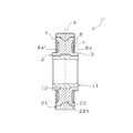
- FIG. 2 is a cross-sectional view taken along line AA of the composite member of FIG.
- FIG. 2 is a cross-sectional view of the composite member of FIG. 1 taken along line BB.
- FIG. 1 is a plan view of a composite member of the present invention
- FIG. 2 is a bottom view thereof
- FIGS. 3 and 4 are axial cross-sectional views cut along respective lines.
- the composite member 1 includes a metal member 11 constituting a bearing portion, an outer resin member 21 interlocking with other members and the like, and an inner resin member 2 that is an annular resin molded body of the present invention. It consists of three members.
- the inner resin member 2 is an injection-molded body of a predetermined resin composition, and is insert-molded on the outer periphery of the metal member 11 and the inner periphery of the outer resin member 21.
- the outer diameter of the composite member 1 is, for example, 80 to 120 mm.
- the inner resin member 2 includes an inner diameter cylindrical portion 3 fixed to the outer periphery of the metal member 11, an outer diameter cylindrical portion 4 fixed to the inner periphery of the outer resin member 21, and the inner diameter cylindrical portion 3 and the outer diameter cylindrical portion 4. It has the disc part 5 provided in between and the some rib 6 and 6 'provided radially on both surfaces of the disc part 5 (refer FIG. 1, FIG. 2). Each rib is provided along the radial direction so as to connect the inner diameter cylindrical portion 3 and the outer diameter cylindrical portion 4, and each rib is arranged at equal intervals (equally) in the circumferential direction.
- the outer diameter of the inner resin member 2 is, for example, 60 to 100 mm.
- the rib 6 includes a rib 6a having a gate mark 8 at the time of injection molding and a rib 6b having no gate mark.
- the rib 6a has a bulging portion 7 having a circumferential width larger than that of the other portion of the rib at an intermediate portion between the inner diameter cylindrical portion 3 and the outer diameter cylindrical portion 4.
- the bulging portion 7 is formed in a substantially circular shape, and a gate mark 8 is formed at substantially the center of the end surface in the axial direction of the bulging portion 7.
- the gate at the time of injection molding is located approximately at the center in the radial direction of the rib, the distance from the gate to the inner cylindrical portion is substantially the same as the distance from the outer cylindrical portion. Excellent.
- the resin moving distance is short, and the occurrence of short shots can be suppressed.
- the circumferential width T1 of the portion other than the bulging portion 7 is 1 to 4 mm, for example, and the maximum circumferential width T2 of the bulging portion 7 depends on the size of the gate hole described later, for example 3 to 3 mm. 7 mm.
- Each circumferential width can be appropriately set as long as it satisfies the relationship of T1 ⁇ T2.
- the circumferential width T2 is 2 to 3 times the circumferential width T1.
- the circumferential width of the rib 6b is set to be the same as the circumferential width T1.
- the ribs 6a and the ribs 6b are alternately arranged in the circumferential direction.
- the weld portion is formed in the rib 6b having the same circumferential distance from each adjacent rib 6a.
- the strength reduction can be suppressed. Therefore, it is preferable that the plurality of ribs 6 be provided so that the number of ribs 6b between adjacent ribs 6a is an odd number (one in FIG. 1) so that a weld portion is formed on the ribs.
- FIG. 2 is a view of the composite member 1 as viewed from the opposite side to FIG. Since the inner resin member 2 is injection-molded from one end in the axial direction, no gate mark is formed on the rib 6 'on the opposite surface.
- the number of ribs 6 (FIG. 1) provided on one surface and the number of ribs 6 ′ (FIG. 2) provided on the opposite surface are the same, and the ribs on each surface overlap in the axial direction.
- the rib 6a ' corresponds to the rib 6a in FIG. 1
- the rib 6b' corresponds to the rib 6b in FIG.
- a bulging portion 7 ′ having a circumferential width larger than that of the other portion of the rib is formed at the substantially radial center of the rib 6 a ′.
- the portion 7 ′ does not necessarily have to be formed.
- the number of ribs on one surface is not particularly limited, and 12 ribs are provided in FIGS. Note that the number of ribs on each surface may be the same or different. Moreover, it is good also as a structure by which the rib was provided only in one side.
- FIG. 3 shows a cross-sectional view taken along line AA of FIG.
- the cross-sectional shape of the composite member 1 is symmetric with respect to the axial center line X except for the presence or absence of gate marks.
- the ribs 6a and 6a ' are formed so that the end surfaces in the axial direction are substantially V-shaped.
- the rib 6 a has the smallest axial length in the bulging portion 7 where the gate mark 8 is formed, and is axially directed from the bulging portion 7 toward the inner diameter cylindrical portion 3 or the outer diameter cylindrical portion 4.
- the length is formed to be long.
- the axial end surface of the rib 6 a is composed of a pair of inclined surfaces inclined toward the radial center and the flat surface of the bulging portion 7.
- the rib 6a ' is formed in the same manner.
- a convex portion 12 that protrudes toward the inner resin member 2 is formed on the outer peripheral surface of the metal member 11.
- a convex portion 22 that protrudes toward the inner resin member 2 is formed on the inner peripheral surface of the outer resin member 21.
- the convex portion 12 and the convex portion 22 are formed on the entire circumference or partly along the circumferential direction. In the form shown in FIG. 3 and FIG. 4, the convex part 12 and the convex part 22 are each formed over the perimeter. The shape of each convex part will not be specifically limited if it is a shape which functions as an engaging part with respect to an inner side resin member.
- the convex portion 12 has a substantially rectangular cross-sectional shape
- the convex portion 22 has undercut portions 22 a that protrude in the axial direction on both side surfaces (both end surfaces in the axial direction). Is substantially cross-shaped. Due to this undercut shape, the outer resin member 21 is less likely to come out in the radial direction with respect to the inner resin member 2.
- a plurality of the convex portions 12 are formed at equal intervals along the circumferential direction of the metal member 11, and the convex portions 22 are formed.
- a plurality of outer resin members 21 are formed at equal intervals along the circumferential direction.
- these convex portions are preferably formed at the same position in the circumferential direction of the composite member 1.
- the position of each convex portion in the circumferential direction is not particularly limited, but may be set from the relationship with the gate position. Specifically, it is preferable to provide a protrusion at a circumferential position of the rib having at least a gate mark. In this case, a convex portion may be further provided at a circumferential position of the rib having no gate mark. By doing so, the molten resin can easily flow into the gap around the convex portion in the cavity.
- the engaging portion is a convex portion that protrudes from the outer peripheral surface of the metal member 11 and the inner peripheral surface of the outer resin member 21 toward the inner resin member 2. Moreover, you may combine a convex part and a recessed part.
- the concave portion of the metal member 11 is formed to be recessed radially inward from the outer peripheral surface of the metal member 11.
- FIG. 4 shows a cross-sectional view taken along the line BB of FIG.
- FIG. 4 is a cross-sectional view in the axial direction at the disc portion where no rib is provided.
- the shape of each convex portion is the same as in FIG.
- L2 is preferably 2 to 5 times L1. More preferably, it is ⁇ 4 times.
- the shape of the outer peripheral surface of the outer resin member 21 of the composite member 1 can be an arbitrary shape, for example, a shape (flat, unevenness, gear, etc.) that can be engaged with or connected to other members.
- the metal member a metal rolling bearing or a sliding bearing is adopted, and a molten metal is used as the material.
- the molten metal material is preferably iron, aluminum, an aluminum alloy, copper, or a copper alloy.
- iron include general structural carbon steel (SS400, etc.), mild steel (SPCC, SPCE, etc.), stainless steel (SUS304, SUS316, etc.), etc.
- Examples of aluminum include A1100 and A1050, examples of aluminum alloys include A2017 and A5052 (including anodized products), examples of copper include C1100, and examples of copper alloys include C2700 and C2801.
- the synthetic resin used for the inner resin member and the outer resin member may be any material that can be injection-molded.
- thermoplastic polyimide resin polyether ketone resin, polyether ether ketone (PEEK) resin, polyphenylene sulfide (PPS) resin , Polyamideimide resin, polyamide (PA) resin, polybutylene terephthalate (PBT) resin, polyethylene terephthalate (PET) resin, polyethylene (PE) resin, polyacetal resin, phenol resin and the like.
- PES polyphenylene sulfide
- PA polyamide
- PBT polybutylene terephthalate
- PET polyethylene terephthalate
- PE polyethylene
- polyacetal resin polyacetal resin
- the numbers in each polyamide resin represent the number of carbons between amide bonds.
- the synthetic resin used for the inner resin member and the synthetic resin used for the outer resin member may be selected according to respective required characteristics.
- a synthetic resin excellent in mechanical properties, dimensional stability, and heat resistance for example, PEEK resin, PPS resin, PA46 resin, etc. Can be mentioned.
- the inner resin member it is preferable to use an inexpensive synthetic resin that is excellent in handleability of injection molding, and examples thereof include PA66 resin.
- PA46 resin for the outer resin member and PA66 resin for the inner resin member because various properties and overall cost of the resin member are excellent.
- Each synthetic resin can be blended with a fibrous reinforcing material and other additives.
- a fibrous reinforcing material glass fiber, carbon fiber or the like is used.
- the glass fiber is obtained by spinning from inorganic glass containing SiO 2 , B 2 O 3 , Al 2 O 3 , CaO, MgO, Na 2 O, K 2 O, Fe 2 O 3 or the like as a main component.
- alkali-free glass (E glass), alkali-containing glass (C glass, A glass) or the like can be used.
- Carbon fiber can be used regardless of the type of raw material such as polyacrylonitrile (PAN), pitch, rayon, and lignin-poval mixture.
- a solid lubricant for example, a solid lubricant, a particulate filler (inorganic filler), an antioxidant, an antistatic agent, a release agent, a colorant and the like can be blended.
- a particulate filler inorganic filler
- an antioxidant for example, an antioxidant, an antistatic agent, a release agent, a colorant and the like
- polytetrafluoroethylene resin, graphite, calcium carbonate, clay, talc, silica, welastonite, elastomer and the like can be blended.
- Each material constituting the inner resin member or the outer resin member is mixed with a Henschel mixer, a ball mixer, a ribbon blender, etc., if necessary, and then melt-kneaded with a melt extruder such as a twin-screw kneading extruder. Each pellet can be obtained.
- the filling material may be fed by side feed when melt-kneading with a twin screw extruder or the like.
- the composite member of the present invention is manufactured by injection molding using the obtained pellets.
- the insert molding of the composite member in FIG. 1 will be described with reference to FIG.
- the insert molding die is composed of a first template 31 and a second template 32.
- the metal member 11 and the outer resin member 21 manufactured in advance are mounted on the molding die.
- the outer resin member 21 is obtained by injection molding using a pellet for the outer resin member.
- the cavity 35 of the inner resin member is formed by the first template 31 and the second template 32 abutting each other.
- 5 shows a partial cross-sectional view, the cavity 35 is formed in an annular shape along the shape of the inner resin member.
- the sprue 33 is provided on one end side in the axial direction of the cavity 35, and the gate 34 communicating with the sprue 33 is provided on the cavity surface 35 a that forms the axial end face of the rib.
- the molten resin collides with the cavity surface 35b facing the cavity surface 35a and spreads in the radial direction, to the cavity forming the inner cylindrical portion and the cavity forming the outer cylindrical portion. Led. Then, it passes through a cavity (not shown) that forms a disk portion, is guided to a cavity (not shown) of an adjacent rib, and merges with molten resin injected from another gate. After the resin is filled, the resin is solidified by cooling for a certain time through holding pressure. Thereafter, the annular resin molded body is obtained by opening the mold.
- the cavity surface 35b facing the gate 34 is formed in a substantially V shape, the molten resin can be smoothly guided to the cavity for the inner diameter cylindrical portion and the cavity for the outer diameter cylindrical portion. As a result, since the molten resin can be uniformly filled in the entire cavity, the molding accuracy is further stabilized and the strength can be made uniform.
- the hole diameter ⁇ of the gate 34 is, for example, 0.5 to 2 mm. As described above, the gate 34 is provided substantially at the center of the bulging portion.
- the relationship between the hole diameter ⁇ and the circumferential width T2 of the bulging portion 7 (see FIG. 1) is preferably such that the circumferential width T2 is 2 to 3 times the hole diameter ⁇ .
- the composite member of the present invention is not limited to the configuration shown in FIGS.
- the cross-sectional shape of the composite member may be asymmetric with respect to the axial center line so that the molten resin can be more smoothly filled during insert molding.
- FIG. 6 shows an enlarged cross-sectional view around the gate in manufacturing an asymmetric composite member.
- the cavity 52 may be formed so that the cavity surface 52a that forms the axial end surface of the rib provided with the gate 51 and the opposed cavity surface 52b are asymmetric.
- the cavity surface 52b has a V-shaped cross section, and the inclination angle of the inclined surface constituting the cavity surface 52b with respect to the abutting surface is made larger than the inclination angle of the inclined surface constituting the cavity surface 52a.
- the guide surface 42 a may be formed by inclining the axial end surface on the gate side of the convex portion 42 of the metal member 41. Since the inner cylindrical portion on the gate side is difficult to be filled with the molten resin, the molten resin can be smoothly filled by providing such a guide surface 42a.
- voids may occur in the molded body due to air remaining.
- the shape of the connecting portion (including the engaging portion) with the other member is a complicated shape, for example, in the case of a gear shape including a plurality of projections and depressions, an air residue tends to occur in the connecting portion.
- FIG. 5 it can be said that air is relatively easily collected in the peripheral portion of the convex portion 22 of the outer resin member 21.
- FIG. 7 is another example of the composite member of the present invention, and has a configuration suitable for suppressing the generation of voids.
- FIG. 7 is a sectional view in the axial direction of the composite member 1 ′ and corresponds to the sectional view in the axial direction of the composite member 1 in FIG. 3.
- the composite member 1 ′ differs from the composite member 1 in the structure of the connecting portion between the inner resin member 2 and the outer resin member 21.
- the convex portion 22 of the outer resin member 21 has inclined surfaces 22b on both side surfaces (end surfaces on both sides in the axial direction) where the axial length of the convex portion increases radially outward.
- the convex portion 22 is not formed with an undercut portion protruding in the axial direction.
- the inner resin member 2 has a shape along the inclined surface 22b.
- the inclined surface 22b may be formed on both end surfaces in the axial direction of the convex portion 22 as shown in FIG. 7, or may be formed on one axial end surface. In the latter case, it is preferable to provide an inclined surface on the end surface in the axial direction opposite to the gate mark 8 where it is considered that air remaining is more likely to occur.
- FIG. 8 shows an enlarged cross-sectional view around the gate in manufacturing the composite member 1 ′.
- the convex part 62 has inclined surfaces 62b on both side surfaces that allow the air inside the molded body to be removed, the molten resin flows well into the entire cavity 72 of the injection mold and molding is performed. Air inside the body is easily pushed out. As a result, generation
- there is no undercut portion projecting in the axial direction of the molded body that is coaxial with the injection direction of the molten resin it is not necessary for the molten resin to wrap around and air can be suitably suppressed. By reducing the remaining amount of air inside the molded body, the product strength can be improved. Moreover, each dimension can be stabilized.
- a protrusion having an undercut portion protruding in the circumferential direction of the composite member may be provided on the convex portion.
- the composite member of the present invention is not limited to three members, and may be composed of at least two members.
- it may consist of two members, a metal member and an inner resin member, or may consist of two members, an inner resin member and an outer resin member.
- the composite member of the present invention can be used as an arbitrary annular part.
- it can be used as a pulley that guides a drive belt that drives automobile engine accessories.
- a drive belt is mounted on the outer peripheral surface made of a resin member.
- the gear may have, for example, an outer resin member having gear teeth formed on the outer peripheral surface, a metal member constituting the core tube, and an inner resin member integrally formed with these members.
- the inner resin member of the present invention can be widely used as an annular member that is required to have shape accuracy because the occurrence of short shots is suppressed and the molding accuracy is excellent.
- the composite member of the present invention can be mainly used as a resin pulley or a resin gear, and can be suitably used particularly for a material having a relatively large outer diameter.
Landscapes
- Engineering & Computer Science (AREA)
- General Engineering & Computer Science (AREA)
- Mechanical Engineering (AREA)
- Manufacturing & Machinery (AREA)
- Physics & Mathematics (AREA)
- Electromagnetism (AREA)
- Thermal Sciences (AREA)
- Moulds For Moulding Plastics Or The Like (AREA)
Abstract
La présente invention a pour objet : un corps moulé en résine annulaire dans lequel l'apparition d'un moulage court est supprimée et qui a une excellente précision de moulage ; et un élément composite comprenant le corps moulé en résine annulaire. À cet effet, selon la présente invention, un élément en résine interne (2) est pourvu de : une partie cylindre de diamètre interne (3) ; une partie cylindre de diamètre externe (4) ; une partie disque (5) disposée entre la partie cylindre de diamètre interne (3) et la partie cylindre de diamètre externe (4) ; et une pluralité de nervures (6) disposées sur la partie disque (5) sous une forme radiale, l'élément en résine interne (2) étant un corps moulé par injection formé par moulage par injection d'une composition de résine et la pluralité de nervures (6) s'étendant uniformément dans la direction circonférentielle à partir de la partie cylindre de diamètre interne (3) jusqu'à la partie cylindre de diamètre externe (4) et ayant des traces de la carotte (8) au niveau des centres radiaux approximatifs d'au moins l'une d'entre elles.
Applications Claiming Priority (4)
| Application Number | Priority Date | Filing Date | Title |
|---|---|---|---|
| JP2018060542 | 2018-03-27 | ||
| JP2018-060542 | 2018-03-27 | ||
| JP2019-053959 | 2019-03-21 | ||
| JP2019053959A JP2019171858A (ja) | 2018-03-27 | 2019-03-21 | 円環状樹脂成形体および複合部材 |
Publications (1)
| Publication Number | Publication Date |
|---|---|
| WO2019189054A1 true WO2019189054A1 (fr) | 2019-10-03 |
Family
ID=68060177
Family Applications (1)
| Application Number | Title | Priority Date | Filing Date |
|---|---|---|---|
| PCT/JP2019/012654 WO2019189054A1 (fr) | 2018-03-27 | 2019-03-26 | Corps moulé en résine annulaire et élément composite |
Country Status (1)
| Country | Link |
|---|---|
| WO (1) | WO2019189054A1 (fr) |
Cited By (1)
| Publication number | Priority date | Publication date | Assignee | Title |
|---|---|---|---|---|
| CN113580466A (zh) * | 2021-07-29 | 2021-11-02 | 何锡田 | 一种同步带轮及制备方法 |
Citations (5)
| Publication number | Priority date | Publication date | Assignee | Title |
|---|---|---|---|---|
| JPH0753950Y2 (ja) * | 1990-11-06 | 1995-12-13 | シチズン時計株式会社 | 成形部品 |
| JPH11193860A (ja) * | 1997-12-29 | 1999-07-21 | Ricoh Co Ltd | 樹脂製の歯車 |
| JP2002036297A (ja) * | 2000-07-28 | 2002-02-05 | Ricoh Co Ltd | 円盤状プラスチック成形品及びその成形方法 |
| JP2003276058A (ja) * | 2002-01-15 | 2003-09-30 | Enplas Corp | 射出成形樹脂歯車、射出成形樹脂回転体及び射出成形体 |
| JP2016093910A (ja) * | 2014-11-12 | 2016-05-26 | キヤノン株式会社 | 歯車および歯車の製造方法 |
-
2019
- 2019-03-26 WO PCT/JP2019/012654 patent/WO2019189054A1/fr active Application Filing
Patent Citations (5)
| Publication number | Priority date | Publication date | Assignee | Title |
|---|---|---|---|---|
| JPH0753950Y2 (ja) * | 1990-11-06 | 1995-12-13 | シチズン時計株式会社 | 成形部品 |
| JPH11193860A (ja) * | 1997-12-29 | 1999-07-21 | Ricoh Co Ltd | 樹脂製の歯車 |
| JP2002036297A (ja) * | 2000-07-28 | 2002-02-05 | Ricoh Co Ltd | 円盤状プラスチック成形品及びその成形方法 |
| JP2003276058A (ja) * | 2002-01-15 | 2003-09-30 | Enplas Corp | 射出成形樹脂歯車、射出成形樹脂回転体及び射出成形体 |
| JP2016093910A (ja) * | 2014-11-12 | 2016-05-26 | キヤノン株式会社 | 歯車および歯車の製造方法 |
Cited By (1)
| Publication number | Priority date | Publication date | Assignee | Title |
|---|---|---|---|---|
| CN113580466A (zh) * | 2021-07-29 | 2021-11-02 | 何锡田 | 一种同步带轮及制备方法 |
Similar Documents
| Publication | Publication Date | Title |
|---|---|---|
| JP2019171858A (ja) | 円環状樹脂成形体および複合部材 | |
| JP4173053B2 (ja) | 射出成形樹脂歯車、射出成形樹脂スプロケット、射出成形樹脂プーリ、射出成形樹脂ローラ | |
| CN112673195B (zh) | 旋转型动力传递部件的制造方法 | |
| JP2002301742A (ja) | 樹脂製リングの射出成形方法 | |
| JP2008213393A (ja) | 樹脂巻き部品 | |
| JP5872942B2 (ja) | 軸受保持器用金型 | |
| WO2019189054A1 (fr) | Corps moulé en résine annulaire et élément composite | |
| JP2006070926A (ja) | 円錐ころ軸受用保持器 | |
| CN108884871A (zh) | 轴承用树脂制保持架及其制造方法以及滚动轴承 | |
| CA2662120A1 (fr) | Moule metallique pour moulage a injection et article ainsi forme | |
| JP2008290402A (ja) | 合成樹脂製プーリの製造方法及び射出成形用金型 | |
| JP5829983B2 (ja) | デリバリパイプの成形方法 | |
| JP5517345B2 (ja) | 樹脂成形品の製造方法 | |
| JP5443089B2 (ja) | 樹脂成形品 | |
| WO2012128349A1 (fr) | Matrice pour moulage par injection, article moulé en résine, et procédé de fabrication de celui-ci | |
| JP6626255B2 (ja) | 転がり軸受用保持器およびその製造方法、並びに転がり軸受 | |
| JP2018161860A (ja) | 熱可塑性樹脂組成物のペレットの製造方法 | |
| WO2023048181A1 (fr) | Support de roulement à rouleaux, et roulement à rouleaux | |
| JP2019072956A (ja) | 樹脂成形体の成形型 | |
| JP5284145B2 (ja) | 円環状外周部を有する樹脂成形品 | |
| JP6277830B2 (ja) | 合成樹脂製プーリの製造方法 | |
| JP2005069243A (ja) | 合成樹脂製プーリ | |
| JP2011075000A (ja) | 合成樹脂製プーリ | |
| JP7058037B2 (ja) | 樹脂成型品の製造方法 | |
| JP2012117568A (ja) | 樹脂製プーリ |
Legal Events
| Date | Code | Title | Description |
|---|---|---|---|
| 121 | Ep: the epo has been informed by wipo that ep was designated in this application |
Ref document number: 19776492 Country of ref document: EP Kind code of ref document: A1 |
|
| NENP | Non-entry into the national phase |
Ref country code: DE |
|
| 122 | Ep: pct application non-entry in european phase |
Ref document number: 19776492 Country of ref document: EP Kind code of ref document: A1 |