WO2019189054A1 - Annular resin molded body and composite member - Google Patents
Annular resin molded body and composite member Download PDFInfo
- Publication number
- WO2019189054A1 WO2019189054A1 PCT/JP2019/012654 JP2019012654W WO2019189054A1 WO 2019189054 A1 WO2019189054 A1 WO 2019189054A1 JP 2019012654 W JP2019012654 W JP 2019012654W WO 2019189054 A1 WO2019189054 A1 WO 2019189054A1
- Authority
- WO
- WIPO (PCT)
- Prior art keywords
- annular
- molded body
- resin
- resin molded
- rib
- Prior art date
Links
Images


Classifications
-
- B—PERFORMING OPERATIONS; TRANSPORTING
- B29—WORKING OF PLASTICS; WORKING OF SUBSTANCES IN A PLASTIC STATE IN GENERAL
- B29C—SHAPING OR JOINING OF PLASTICS; SHAPING OF MATERIAL IN A PLASTIC STATE, NOT OTHERWISE PROVIDED FOR; AFTER-TREATMENT OF THE SHAPED PRODUCTS, e.g. REPAIRING
- B29C45/00—Injection moulding, i.e. forcing the required volume of moulding material through a nozzle into a closed mould; Apparatus therefor
- B29C45/14—Injection moulding, i.e. forcing the required volume of moulding material through a nozzle into a closed mould; Apparatus therefor incorporating preformed parts or layers, e.g. injection moulding around inserts or for coating articles
-
- B—PERFORMING OPERATIONS; TRANSPORTING
- B29—WORKING OF PLASTICS; WORKING OF SUBSTANCES IN A PLASTIC STATE IN GENERAL
- B29D—PRODUCING PARTICULAR ARTICLES FROM PLASTICS OR FROM SUBSTANCES IN A PLASTIC STATE
- B29D15/00—Producing gear wheels or similar articles with grooves or projections, e.g. control knobs
-
- F—MECHANICAL ENGINEERING; LIGHTING; HEATING; WEAPONS; BLASTING
- F16—ENGINEERING ELEMENTS AND UNITS; GENERAL MEASURES FOR PRODUCING AND MAINTAINING EFFECTIVE FUNCTIONING OF MACHINES OR INSTALLATIONS; THERMAL INSULATION IN GENERAL
- F16H—GEARING
- F16H55/00—Elements with teeth or friction surfaces for conveying motion; Worms, pulleys or sheaves for gearing mechanisms
- F16H55/02—Toothed members; Worms
- F16H55/06—Use of materials; Use of treatments of toothed members or worms to affect their intrinsic material properties
-
- F—MECHANICAL ENGINEERING; LIGHTING; HEATING; WEAPONS; BLASTING
- F16—ENGINEERING ELEMENTS AND UNITS; GENERAL MEASURES FOR PRODUCING AND MAINTAINING EFFECTIVE FUNCTIONING OF MACHINES OR INSTALLATIONS; THERMAL INSULATION IN GENERAL
- F16H—GEARING
- F16H55/00—Elements with teeth or friction surfaces for conveying motion; Worms, pulleys or sheaves for gearing mechanisms
- F16H55/32—Friction members
- F16H55/36—Pulleys
- F16H55/48—Pulleys manufactured exclusively or in part of non-metallic material, e.g. plastics
Abstract
The purpose of the present invention is to provide: an annular resin molded body in which occurrence of short shot is suppressed and which has excellent molding accuracy; and a composite member including the annular resin molded body. According to the present invention, an inner resin member 2 is provided with: an inner diameter cylinder part 3; an outer diameter cylinder part 4; a disk part 5 provided between the inner diameter cylinder part 3 and the outer diameter cylinder part 4; and a plurality of ribs 6 provided on the disk part 5 in a radial shape, wherein the inner resin member 2 is an injection molded body formed by injection molding a resin composition, and the plurality of ribs 6 extends uniformly in the circumferential direction from the inner diameter cylinder part 3 to the outer diameter cylinder part 4, and have gate marks 8 at the approximate radial centers of at least one thereof.
Description
本発明は、円環状樹脂成形体および該円環状樹脂成形体を含む複合部材に関する。
The present invention relates to an annular resin molded body and a composite member including the annular resin molded body.
従来、産業機械や自動車などにおいて、軽量化や低コスト化を図るために樹脂製プーリや樹脂製ギヤといった円環状の複合部材が用いられている。例えば、樹脂製プーリは、エンジン補機類を駆動する駆動ベルトの案内などに用いられ、転がり軸受の外周に合成樹脂を一体成形したものが知られている。このような樹脂製プーリは、射出成形金型内に転がり軸受を配置し、該転がり軸受の外輪外周部に形成されたキャビティ内に溶融樹脂を充填することで製造される。
Conventionally, annular composite members such as resin pulleys and resin gears have been used in industrial machines and automobiles in order to reduce weight and cost. For example, a resin pulley is used for guiding a driving belt for driving engine accessories and the like, and a synthetic resin integrally formed on the outer periphery of a rolling bearing is known. Such a resin pulley is manufactured by disposing a rolling bearing in an injection mold and filling molten resin into a cavity formed on the outer peripheral portion of the outer ring of the rolling bearing.
樹脂製プーリや樹脂製ギヤといった円環状の複合部材は、外周面の形状精度が重要であり、外周部を構成する円環状の樹脂成形体には高い成形精度が要求される。該成形体の成形精度を高める手段として、射出成形時のゲートの位置を工夫した技術などが知られている。
For circular composite members such as resin pulleys and resin gears, the shape accuracy of the outer peripheral surface is important, and high molding accuracy is required for the annular resin molded body constituting the outer peripheral portion. As a means for improving the molding accuracy of the molded body, a technique in which the position of the gate at the time of injection molding is devised is known.
例えば、特許文献1には、軸受と、軸受の外周に一体形成された樹脂部本体とからなる樹脂製プーリが開示されている。この樹脂部本体は、円板状の基部と、基部の内周部および外周部に沿って基部の略厚さ方向に張り出し形成された円筒状の内径部および外径部と、基部の内周部から外周部へと放射状に延びるとともに基部の略厚さ方向に突出する多数のリブとを有している。特許文献1の技術では、射出成形時において、複数のピンゲートの各々を、隣接するリブ間に内径側円筒部の一方の端面の周方向に沿って略等間隔で配置することで、成形精度の向上を図っている。
For example, Patent Document 1 discloses a resin pulley including a bearing and a resin part body integrally formed on the outer periphery of the bearing. The resin portion main body includes a disc-shaped base, a cylindrical inner diameter portion and an outer diameter portion that are formed to extend in the thickness direction of the base portion along the inner peripheral portion and the outer peripheral portion of the base portion, and the inner periphery of the base portion. And a large number of ribs extending radially from the outer periphery to the outer peripheral portion and projecting in the substantially thickness direction of the base portion. In the technique of Patent Document 1, at the time of injection molding, each of the plurality of pin gates is arranged at substantially equal intervals along the circumferential direction of one end face of the inner diameter side cylindrical portion between adjacent ribs, thereby achieving high molding accuracy. We are trying to improve.
しかしながら、特許文献1の技術では、小径の円環状樹脂成形体の場合には、成形精度がある程度維持されるものの、例えば外径が60mmを超えるといった比較的大径の円環状樹脂成形体の場合には、ゲート位置が樹脂成形体の内径側にあると、外径側にまで溶融樹脂が流れにくい。樹脂成形体の外径側まで溶融樹脂が円滑に流れていかないと、ショートショットが生じ、成形精度の悪化や真円度の悪化につながるおそれがある。
However, in the technique of Patent Document 1, in the case of an annular resin molded body having a small diameter, although the molding accuracy is maintained to some extent, for example, an annular resin molded body having a relatively large diameter such as an outer diameter exceeding 60 mm. If the gate position is on the inner diameter side of the resin molded body, the molten resin hardly flows to the outer diameter side. If the molten resin does not flow smoothly to the outer diameter side of the resin molded body, short shots occur, which may lead to deterioration in molding accuracy and roundness.
本発明はこのような事情に鑑みてなされたものであり、ショートショットの発生が抑制され、成形精度に優れた円環状樹脂成形体および該円環状樹脂成形体を含む複合部材を提供することを目的とする。
The present invention has been made in view of such circumstances, and provides an annular resin molded body in which occurrence of short shots is suppressed and excellent in molding accuracy, and a composite member including the annular resin molded body. Objective.
本発明の円環状樹脂成形体は、内径円筒部と、外径円筒部と、該内径円筒部および該外径円筒部の間に設けられた円板部と、該円板部に放射状に設けられた複数のリブとを備える円環状樹脂成形体であって、上記円環状樹脂成形体は、樹脂組成物を射出成形してなる射出成形体であり、上記複数のリブは、円周方向に均等に、かつ、上記内径円筒部から上記外径円筒部にかけて延設され、該複数のリブの少なくとも1つの径方向略中央にゲート痕を有することを特徴とする。
The annular resin molded body of the present invention includes an inner diameter cylindrical portion, an outer diameter cylindrical portion, a disk portion provided between the inner diameter cylindrical portion and the outer diameter cylindrical portion, and a radial portion provided on the disk portion. A ring-shaped resin molded body provided with a plurality of ribs, wherein the ring-shaped resin molded body is an injection-molded body formed by injection molding a resin composition, and the plurality of ribs are arranged in a circumferential direction. It is evenly extended from the inner diameter cylindrical portion to the outer diameter cylindrical portion, and has a gate mark at substantially the center in the radial direction of at least one of the plurality of ribs.
上記ゲート痕を有するリブは、径方向略中央に、周方向幅が該リブの他の部分よりも大きく形成された膨出部を有しており、該膨出部の軸方向端面に上記ゲート痕が形成されていることを特徴とする。
The rib having the gate trace has a bulging portion formed at a substantially central portion in the radial direction and having a circumferential width larger than other portions of the rib, and the gate is formed on an axial end surface of the bulging portion. A scar is formed.
上記ゲート痕を有するリブは、軸方向断面において略V字状に形成され、該リブの軸方向端面は、径方向中央に向けて傾斜した一対の傾斜面を有していることを特徴とする。
The rib having the gate mark is formed in a substantially V shape in the axial cross section, and the axial end face of the rib has a pair of inclined surfaces inclined toward the radial center. .
上記複数のリブは、上記ゲート痕を有するリブAと、上記ゲート痕を有さないリブBとから構成され、上記リブAと上記リブBと周方向で交互に配置されていることを特徴とする。
The plurality of ribs are composed of a rib A having the gate mark and a rib B having no gate mark, and the rib A and the rib B are alternately arranged in the circumferential direction. To do.
本発明の複合部材は、円環状金属部材と、該円環状金属部材の外周に一体成形された本発明の円環状樹脂成形体とを備え、上記円環状金属部材の外周面に凸部および凹部の少なくとも一方が周方向に沿って形成され、上記円環状樹脂成形体の内径円筒部の内周面が、該凸部または該凹部に係合していることを特徴とする。
The composite member of the present invention includes an annular metal member and the annular resin molded body of the present invention integrally formed on the outer periphery of the annular metal member, and a convex portion and a concave portion on the outer peripheral surface of the annular metal member. Is formed along the circumferential direction, and the inner peripheral surface of the inner diameter cylindrical portion of the annular resin molded body is engaged with the convex portion or the concave portion.
本発明の複合部材は、円環状樹脂部材と、該円環状樹脂部材の内周に一体成形された本発明の円環状樹脂成形体とを備え、上記円環状樹脂部材の内周面に凸部および凹部の少なくとも一方が周方向に沿って形成され、上記円環状樹脂成形体の外径円筒部の外周面が、該凸部または該凹部に係合していることを特徴とする。
The composite member of the present invention includes an annular resin member and the annular resin molded body of the present invention integrally molded on the inner periphery of the annular resin member, and a convex portion on the inner peripheral surface of the annular resin member. And at least one of the recesses is formed along a circumferential direction, and an outer peripheral surface of an outer diameter cylindrical portion of the annular resin molded body is engaged with the protrusion or the recess.
上記円環状樹脂部材の内周面に上記凸部が形成され、上記円環状樹脂成形体の外径円筒部の外周面が上記凸部に係合しており、上記凸部は、上記複合部材の軸方向における上記凸部の側面の少なくともいずれか一方に、径方向外側に向かって上記凸部の軸方向長さが大きくなる傾斜面を有することを特徴とする。
The convex portion is formed on the inner peripheral surface of the annular resin member, the outer peripheral surface of the outer cylindrical portion of the annular resin molded body is engaged with the convex portion, and the convex portion is the composite member. At least one of the side surfaces of the convex portion in the axial direction has an inclined surface in which the axial length of the convex portion increases radially outward.
本発明の複合部材は、円環状金属部材と、円環状樹脂部材と、該円環状金属部材の外周で、かつ、該円環状樹脂部材の内周に一体成形された本発明の円環状樹脂成形体とを備え、上記円環状金属部材の外周面に凸部および凹部の少なくとも一方が形成され、上記円環状樹脂成形体の内径円筒部の内周面が、該凸部または該凹部に係合し、上記円環状樹脂部材の内周面に凸部および凹部の少なくとも一方が形成され、上記円環状樹脂成形体の外径円筒部の外周面が、該凸部または該凹部に係合していることを特徴とする。
The composite member of the present invention includes an annular metal member, an annular resin member, an outer periphery of the annular metal member, and an annular resin molding of the present invention integrally formed on the inner periphery of the annular resin member. And at least one of a convex portion and a concave portion is formed on the outer peripheral surface of the annular metal member, and the inner peripheral surface of the inner diameter cylindrical portion of the annular resin molded body is engaged with the convex portion or the concave portion. And at least one of a convex portion and a concave portion is formed on the inner peripheral surface of the annular resin member, and the outer peripheral surface of the outer diameter cylindrical portion of the annular resin molded body is engaged with the convex portion or the concave portion. It is characterized by being.
本発明の円環状樹脂成形体は、円板部に放射状に設けられた複数のリブを備え、複数のリブは、円周方向に均等に、かつ、内径円筒部から外径円筒部にかけて延設され、該複数のリブの少なくとも1つの径方向略中央にゲート痕を有するので、射出成形時には、キャビティ内の隅々にまで溶融樹脂が円滑に流れ込むことができる。その結果、成形体の内径円筒部にショートショットが生じることが回避され、かつ、成形体の外径円筒部にショートショットが生じることが回避され、成形精度に優れた円環状樹脂成形体が得られる。
The annular resin molded body of the present invention includes a plurality of ribs provided radially on the disk portion, and the plurality of ribs extend evenly in the circumferential direction from the inner diameter cylindrical portion to the outer diameter cylindrical portion. In addition, since the gate mark is provided at approximately the center in the radial direction of at least one of the plurality of ribs, the molten resin can smoothly flow into every corner in the cavity during injection molding. As a result, a short shot is prevented from occurring in the inner diameter cylindrical portion of the molded body, and a short shot is prevented from occurring in the outer diameter cylindrical portion of the molded body, thereby obtaining an annular resin molded body excellent in molding accuracy. It is done.
射出成形においてリブ上にゲートを設ける場合、例えば、ゲート痕とリブの幅が同じであると、成形金型から成形体を取り出す際にリブの一部が折れるなどして所望の形状とならないことが懸念される。この点、上記円環状樹脂成形体では、ゲート痕を有するリブは、径方向略中央に周方向幅が大きい膨出部を有しており、該膨出部の軸方向端面にゲート痕が形成されるので、成形体を取り出す際にもリブの一部が折れるなどの不具合が生じることなく、所望の形状の円環状樹脂成形体が得られる。
When a gate is provided on a rib in injection molding, for example, if the gate trace and the width of the rib are the same, when the molded product is taken out from the molding die, the rib does not break and does not have the desired shape. Is concerned. In this respect, in the annular resin molded body, the rib having the gate trace has a bulging portion having a large circumferential width at the substantially center in the radial direction, and the gate trace is formed on the axial end surface of the bulging portion. Therefore, an annular resin molded body having a desired shape can be obtained without causing problems such as part of the ribs being broken even when the molded body is taken out.
上記ゲート痕を有するリブは、軸方向断面において略V字状に形成され、該リブの軸方向端面は、径方向中央に向けて傾斜した一対の傾斜面を有しているので、ゲート痕はリブの窪んだ箇所に形成され、目立ちにくく、各種動作に干渉することがない。
The rib having the gate trace is formed in a substantially V shape in the axial section, and the axial end surface of the rib has a pair of inclined surfaces inclined toward the center in the radial direction. It is formed in a recessed portion of the rib, is not conspicuous, and does not interfere with various operations.
上記複数のリブは、ゲート痕を有するリブAと、ゲート痕を有さないリブBとから構成され、リブAとリブBと周方向で交互に配置されているので、溶融樹脂の接合部であるウェルド部がゲート痕を有さないリブBに形成されるため、ウェルド部による強度低下を抑制できる。
The plurality of ribs are composed of a rib A having a gate trace and a rib B having no gate trace, and are arranged alternately in the circumferential direction with the rib A and the rib B. Since a certain weld portion is formed on the rib B having no gate trace, a decrease in strength due to the weld portion can be suppressed.
本発明の複合部材は、本発明の円環状樹脂成形体と、円環状金属部材または円環状樹脂部材とが一体成形されたものであり、該円環状金属部材または該円環状樹脂部材に形成された凸部および凹部の少なくともいずれかに円環状樹脂成形体の円筒部が係合するので、各部材が確実に一体化された複合部材が得られる。具体的には、成形金型のキャビティ内に円環状金属部材または円環状樹脂部材を装着して、溶融樹脂をキャビティ内に流し込む際に、上記凸部または上記凹部の周囲に溶融樹脂が流れ込むことで、例えば、各部材を抱え込む形となり、各部材が円環状樹脂成形体から外れることを防止できる。
The composite member of the present invention is formed by integrally forming the annular resin molded body of the present invention and an annular metal member or an annular resin member, and is formed on the annular metal member or the annular resin member. Since the cylindrical portion of the annular resin molded body is engaged with at least one of the convex portion and the concave portion, a composite member in which the respective members are reliably integrated is obtained. Specifically, when the annular metal member or the annular resin member is mounted in the cavity of the molding die and the molten resin is poured into the cavity, the molten resin flows around the convex portion or the concave portion. Thus, for example, each member is held, and each member can be prevented from being detached from the annular resin molded body.
特に、本発明の複合部材が、円環状樹脂成形体と円環状樹脂部材とが一体成形されたものであり、円環状樹脂部材の内周面に凸部が形成され、円環状樹脂成形体の外径円筒部の外周面が上記凸部に係合しており、該凸部は、複合部材の軸方向における凸部の側面の少なくともいずれか一方に、径方向外側に向かって凸部の軸方向長さが大きくなる傾斜面を有するので、この傾斜面に沿って樹脂が充填されることで射出成形時に空気が押し出されやすくなり、ボイド(巣)の発生を抑制できる。
In particular, the composite member of the present invention is an annular resin molded body and an annular resin member that are integrally molded, and a convex portion is formed on the inner peripheral surface of the annular resin member. The outer peripheral surface of the outer diameter cylindrical portion is engaged with the convex portion, and the convex portion is at least one of the side surfaces of the convex portion in the axial direction of the composite member, and the axis of the convex portion is directed radially outward. Since it has an inclined surface whose direction length increases, filling the resin along the inclined surface makes it easy for air to be pushed out during injection molding, thereby suppressing the generation of voids (nests).
本発明の複合部材は、本発明の円環状樹脂成形体と、円環状金属部材と、円環状樹脂部材とが一体成形されたものであり、該円環状金属部材および該円環状樹脂部材にそれぞれ形成された凸部および凹部の少なくともいずれかに円環状樹脂成形体の円筒部が係合するので、各部材が確実に一体化された複合部材が得られる。また、3部材からなる構成とすることで、例えば、強度が重要となる円環状金属部品と、耐摩耗性、摺動性が重要となる円環状樹脂部材とが、円環状樹脂成形体を介して一体化され、内側に円環状金属部材、外側に円環状樹脂部材を、円環状樹脂成形体で繋ぎ止めることで、特殊な特性に対応した複合部材が得られる。
The composite member of the present invention is formed by integrally molding the annular resin molded body, the annular metal member, and the annular resin member of the present invention, and each of the annular metal member and the annular resin member. Since the cylindrical portion of the annular resin molded body is engaged with at least one of the formed convex portion and concave portion, a composite member in which the respective members are reliably integrated is obtained. In addition, by configuring with three members, for example, an annular metal part in which strength is important and an annular resin member in which wear resistance and slidability are important are interposed via an annular resin molded body. By combining the annular metal member on the inner side and the annular resin member on the outer side with an annular resin molded body, a composite member corresponding to special characteristics can be obtained.
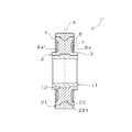
本発明の複合部材の一例を図1~図4に基づいて説明する。図1は本発明の複合部材の平面図であり、図2はその底面図であり、図3および図4は各線で切断した軸方向断面図である。
An example of the composite member of the present invention will be described with reference to FIGS. FIG. 1 is a plan view of a composite member of the present invention, FIG. 2 is a bottom view thereof, and FIGS. 3 and 4 are axial cross-sectional views cut along respective lines.
図1に示すように、複合部材1は、軸受部を構成する金属部材11と、他部材等と連動する外側樹脂部材21と、本発明の円環状樹脂成形体である内側樹脂部材2とを備えた3部材からなっている。内側樹脂部材2は、所定の樹脂組成物の射出成形体であり、金属部材11の外周および外側樹脂部材21の内周にインサート成形される。複合部材1の外径は、例えば80~120mmである。
As shown in FIG. 1, the composite member 1 includes a metal member 11 constituting a bearing portion, an outer resin member 21 interlocking with other members and the like, and an inner resin member 2 that is an annular resin molded body of the present invention. It consists of three members. The inner resin member 2 is an injection-molded body of a predetermined resin composition, and is insert-molded on the outer periphery of the metal member 11 and the inner periphery of the outer resin member 21. The outer diameter of the composite member 1 is, for example, 80 to 120 mm.
内側樹脂部材2は、金属部材11の外周に固定される内径円筒部3と、外側樹脂部材21の内周に固定される外径円筒部4と、内径円筒部3および外径円筒部4の間に設けられた円板部5と、円板部5の両面に放射状に設けられた複数のリブ6、6’とを有する(図1、図2参照)。各リブは、内径円筒部3と外径円筒部4を連結するように径方向に沿って設けられ、それぞれが円周方向に等間隔に(均等に)配置されている。内側樹脂部材2の外径は、例えば60~100mmである。円環状の樹脂成形体において、外径が60mmを超えると、溶融樹脂の流動距離の差などから、ショートショットなどの不具合が生じやすいが、本発明は、外径60mmをこえる比較的大径の樹脂成形体であっても不具合なく製造できる。
The inner resin member 2 includes an inner diameter cylindrical portion 3 fixed to the outer periphery of the metal member 11, an outer diameter cylindrical portion 4 fixed to the inner periphery of the outer resin member 21, and the inner diameter cylindrical portion 3 and the outer diameter cylindrical portion 4. It has the disc part 5 provided in between and the some rib 6 and 6 'provided radially on both surfaces of the disc part 5 (refer FIG. 1, FIG. 2). Each rib is provided along the radial direction so as to connect the inner diameter cylindrical portion 3 and the outer diameter cylindrical portion 4, and each rib is arranged at equal intervals (equally) in the circumferential direction. The outer diameter of the inner resin member 2 is, for example, 60 to 100 mm. In an annular resin molded body, if the outer diameter exceeds 60 mm, problems such as short shots are likely to occur due to differences in the flow distance of the molten resin, but the present invention has a relatively large diameter exceeding 60 mm. Even if it is a resin molding, it can manufacture without a malfunction.
図1に示すように、リブ6は、射出成形時のゲート痕8を有するリブ6aと、ゲート痕を有さないリブ6bとから構成される。リブ6aは、内径円筒部3と外径円筒部4との中間部分に、周方向幅が該リブの他の部分よりも大きく形成された膨出部7を有している。膨出部7は、略円形状に形成されており、その膨出部7の軸方向端面の略中央にゲート痕8が形成される。すなわち、リブの径方向略中央に射出成形時のゲートが位置することになるので、ゲートから内径円筒部までの距離と外径円筒部までの距離とが略同一となり、溶融樹脂の流動パランスに優れる。その結果、例えば、ゲートを内径円筒部に設ける場合に比べて、樹脂の移動距離が短く、ショートショットの発生を抑制できる。
As shown in FIG. 1, the rib 6 includes a rib 6a having a gate mark 8 at the time of injection molding and a rib 6b having no gate mark. The rib 6a has a bulging portion 7 having a circumferential width larger than that of the other portion of the rib at an intermediate portion between the inner diameter cylindrical portion 3 and the outer diameter cylindrical portion 4. The bulging portion 7 is formed in a substantially circular shape, and a gate mark 8 is formed at substantially the center of the end surface in the axial direction of the bulging portion 7. In other words, since the gate at the time of injection molding is located approximately at the center in the radial direction of the rib, the distance from the gate to the inner cylindrical portion is substantially the same as the distance from the outer cylindrical portion. Excellent. As a result, for example, as compared with the case where the gate is provided in the inner cylindrical portion, the resin moving distance is short, and the occurrence of short shots can be suppressed.
リブ6aにおいて、膨出部7以外の部分の周方向幅T1は、例えば1~4mmであり、膨出部7の最大周方向幅T2は後述するゲート孔のサイズにもよるが、例えば3~7mmである。各周方向幅は、T1<T2の関係を満たす範囲であれば適宜設定でき、好ましくは、周方向幅T2が周方向幅T1の2~3倍である。なお、リブ6bの周方向幅は、例えば周方向幅T1と同一に設定される。
In the rib 6a, the circumferential width T1 of the portion other than the bulging portion 7 is 1 to 4 mm, for example, and the maximum circumferential width T2 of the bulging portion 7 depends on the size of the gate hole described later, for example 3 to 3 mm. 7 mm. Each circumferential width can be appropriately set as long as it satisfies the relationship of T1 <T2. Preferably, the circumferential width T2 is 2 to 3 times the circumferential width T1. For example, the circumferential width of the rib 6b is set to be the same as the circumferential width T1.
図1に示すように、内側樹脂部材2においてリブ6aとリブ6bは周方向に交互に配置される。このようにゲート痕8を有するリブ6aを1つおきに配置することで、ウェルド部が、隣接する各リブ6aからの周方向上の距離が等しくなるリブ6bに形成されるため、ウェルド部での強度低下を抑制できる。そのため、リブにウェルド部が形成されるように、複数のリブ6は、隣接するリブ6a間のリブ6bの数が奇数(図1では1つ)となるよう設けることが好ましい。
As shown in FIG. 1, in the inner resin member 2, the ribs 6a and the ribs 6b are alternately arranged in the circumferential direction. By arranging every other rib 6a having the gate marks 8 in this way, the weld portion is formed in the rib 6b having the same circumferential distance from each adjacent rib 6a. The strength reduction can be suppressed. Therefore, it is preferable that the plurality of ribs 6 be provided so that the number of ribs 6b between adjacent ribs 6a is an odd number (one in FIG. 1) so that a weld portion is formed on the ribs.
図2は、複合部材1を図1とは反対側から見た図である。内側樹脂部材2は、軸方向一端側から射出成形されることから、反対面のリブ6’にはゲート痕が形成されていない。内側樹脂部材2において、片方の面に設けられたリブ6(図1)と、反対面に設けられたリブ6’(図2)は同じ数であり、各面のリブは軸方向でそれぞれ重なる位置に設けられる。ここで、リブ6a’は図1のリブ6aに対応し、リブ6b’は図1のリブ6bに対応している。図1と同様に、リブ6a’の径方向略中央には、周方向幅が該リブの他の部分よりも大きく形成された膨出部7’が形成されているが、反対面において膨出部7’は必ずしも形成されていなくてもよい。
FIG. 2 is a view of the composite member 1 as viewed from the opposite side to FIG. Since the inner resin member 2 is injection-molded from one end in the axial direction, no gate mark is formed on the rib 6 'on the opposite surface. In the inner resin member 2, the number of ribs 6 (FIG. 1) provided on one surface and the number of ribs 6 ′ (FIG. 2) provided on the opposite surface are the same, and the ribs on each surface overlap in the axial direction. Provided in position. Here, the rib 6a 'corresponds to the rib 6a in FIG. 1, and the rib 6b' corresponds to the rib 6b in FIG. As in FIG. 1, a bulging portion 7 ′ having a circumferential width larger than that of the other portion of the rib is formed at the substantially radial center of the rib 6 a ′. The portion 7 ′ does not necessarily have to be formed.
片方の面におけるリブの数は、特に限定されず、図1および図2では12本のリブがそれぞれ設けられている。なお、各面におけるリブの数は同じでも、互いに異なっていてもよい。また、片方の面にのみリブが設けられた構成としてもよい。
The number of ribs on one surface is not particularly limited, and 12 ribs are provided in FIGS. Note that the number of ribs on each surface may be the same or different. Moreover, it is good also as a structure by which the rib was provided only in one side.
図3には、図1のA-A線断面図を示す。図3に示すように、複合部材1の断面形状は軸方向中心線Xに対しゲート痕の有無を除いて対称となっている。リブ6a、6a’は、軸方向端面が略V字状に形成される。具体的には、リブ6aは、ゲート痕8が形成された膨出部7において軸方向長さが最も小さくなり、膨出部7から内径円筒部3または外径円筒部4に向けて軸方向長さが長くなるように形成される。この場合、リブ6aの軸方向端面は、径方向中央に向けて傾斜した一対の傾斜面と膨出部7の平面とから構成される。ゲート痕は有しないが、リブ6a’も同様に形成されている。
FIG. 3 shows a cross-sectional view taken along line AA of FIG. As shown in FIG. 3, the cross-sectional shape of the composite member 1 is symmetric with respect to the axial center line X except for the presence or absence of gate marks. The ribs 6a and 6a 'are formed so that the end surfaces in the axial direction are substantially V-shaped. Specifically, the rib 6 a has the smallest axial length in the bulging portion 7 where the gate mark 8 is formed, and is axially directed from the bulging portion 7 toward the inner diameter cylindrical portion 3 or the outer diameter cylindrical portion 4. The length is formed to be long. In this case, the axial end surface of the rib 6 a is composed of a pair of inclined surfaces inclined toward the radial center and the flat surface of the bulging portion 7. Although there is no gate mark, the rib 6a 'is formed in the same manner.
図3の軸方向断面図において、金属部材11の外周面には内側樹脂部材2に向かって突出した凸部12が形成されている。また、外側樹脂部材21の内周面には内側樹脂部材2に向かって突出した凸部22が形成されている。射出成形時には、各凸部を覆うように溶融樹脂が流れ込むため、内径円筒部3が金属部材11を抱え込む形となり、また、外径円筒部4が外側樹脂部材21を抱え込む形となる。これにより、各部材と内側樹脂部材2とが安定して固定され、外れることが防止できる。このように凸部12、22は内側樹脂部材との係合部として機能する。
3, a convex portion 12 that protrudes toward the inner resin member 2 is formed on the outer peripheral surface of the metal member 11. A convex portion 22 that protrudes toward the inner resin member 2 is formed on the inner peripheral surface of the outer resin member 21. At the time of injection molding, since the molten resin flows so as to cover each convex portion, the inner cylindrical portion 3 holds the metal member 11, and the outer cylindrical portion 4 holds the outer resin member 21. Thereby, each member and the inner side resin member 2 are stably fixed, and it can prevent that it remove | deviates. Thus, the convex parts 12 and 22 function as an engaging part with an inner side resin member.
凸部12および凸部22は、それぞれ周方向に沿って全周にまたは一部に形成される。図3および図4に示す形態では、凸部12および凸部22はそれぞれ全周にわたり形成されている。各凸部の形状は、内側樹脂部材に対し係合部として機能する形状であれば、特に限定されない。図3において、凸部12は、断面形状が略矩形状であり、凸部22は、両側面(軸方向両端面)に軸方向にそれぞれ張り出したアンダーカット部22aを有しており、断面形状が略十字状である。このアンダーカット形状により、外側樹脂部材21が内側樹脂部材2に対して径方向へ抜けにくくなっている。
The convex portion 12 and the convex portion 22 are formed on the entire circumference or partly along the circumferential direction. In the form shown in FIG. 3 and FIG. 4, the convex part 12 and the convex part 22 are each formed over the perimeter. The shape of each convex part will not be specifically limited if it is a shape which functions as an engaging part with respect to an inner side resin member. In FIG. 3, the convex portion 12 has a substantially rectangular cross-sectional shape, and the convex portion 22 has undercut portions 22 a that protrude in the axial direction on both side surfaces (both end surfaces in the axial direction). Is substantially cross-shaped. Due to this undercut shape, the outer resin member 21 is less likely to come out in the radial direction with respect to the inner resin member 2.
また、凸部12および凸部22が周方向に沿って一部に形成される構成では、例えば、凸部12が金属部材11の周方向に沿って等間隔に複数形成され、凸部22が外側樹脂部材21の周方向に沿って等間隔に複数形成される。この場合、これら凸部は、複合部材1の周方向で同じ位置に形成されることが好ましい。また、各凸部の周方向における位置は、特に限定されないが、ゲート位置との関係から設定するとよい。具体的には、少なくともゲート痕を有するリブの周方向位置に凸部を設けることが好ましい。この場合、さらに、ゲート痕を有さないリブの周方向位置にも凸部を設けてもよい。こうすることで、キャビティ内の凸部周囲の隙間に溶融樹脂が流れ込みやすくなる。
In the configuration in which the convex portions 12 and the convex portions 22 are partially formed along the circumferential direction, for example, a plurality of the convex portions 12 are formed at equal intervals along the circumferential direction of the metal member 11, and the convex portions 22 are formed. A plurality of outer resin members 21 are formed at equal intervals along the circumferential direction. In this case, these convex portions are preferably formed at the same position in the circumferential direction of the composite member 1. Further, the position of each convex portion in the circumferential direction is not particularly limited, but may be set from the relationship with the gate position. Specifically, it is preferable to provide a protrusion at a circumferential position of the rib having at least a gate mark. In this case, a convex portion may be further provided at a circumferential position of the rib having no gate mark. By doing so, the molten resin can easily flow into the gap around the convex portion in the cavity.
なお、図3では、係合部を、金属部材11の外周面および外側樹脂部材21の内周面から内側樹脂部材2に向かってそれぞれ突出した凸部としたが、凸部に代えて凹部としてもよく、また、凸部と凹部を組み合わせてもよい。例えば、金属部材11の凹部は、金属部材11の外周面から径方向内側に窪んで形成される。
In FIG. 3, the engaging portion is a convex portion that protrudes from the outer peripheral surface of the metal member 11 and the inner peripheral surface of the outer resin member 21 toward the inner resin member 2. Moreover, you may combine a convex part and a recessed part. For example, the concave portion of the metal member 11 is formed to be recessed radially inward from the outer peripheral surface of the metal member 11. *
図4には、図1のB-B線断面図を示す。図4は、リブが設けられていない円板部での軸方向断面図である。図4の断面図において、各凸部の形状は、図3と同様である。ここで、円板部5の軸方向長さをL1、ゲート痕8の位置における両面のリブを含む軸方向長さをL2とすると、L2はL1の2~5倍であることが好ましく、3~4倍であることがより好ましい。L2をL1の2~5倍の範囲とすることで、リブの軸方向端面から充填された溶融樹脂が円板部にスムーズに誘導される。
FIG. 4 shows a cross-sectional view taken along the line BB of FIG. FIG. 4 is a cross-sectional view in the axial direction at the disc portion where no rib is provided. In the cross-sectional view of FIG. 4, the shape of each convex portion is the same as in FIG. Here, assuming that the axial length of the disc portion 5 is L1 and the axial length including ribs on both sides at the position of the gate mark 8 is L2, L2 is preferably 2 to 5 times L1. More preferably, it is ˜4 times. By setting L2 in the range of 2 to 5 times L1, the molten resin filled from the axial end surface of the rib is smoothly guided to the disc portion.
なお、複合部材1の外側樹脂部材21の外周面の形状は任意の形状とでき、例えば、他部材等と係合や連結して連動するような形状(フラット、凹凸、歯車等)とできる。
In addition, the shape of the outer peripheral surface of the outer resin member 21 of the composite member 1 can be an arbitrary shape, for example, a shape (flat, unevenness, gear, etc.) that can be engaged with or connected to other members.
金属部材としては、金属製の転がり軸受やすべり軸受が採用され、材質には溶製金属が用いられる。溶製金属材質としては、鉄、アルミニウム、アルミニウム合金、銅、または銅合金であることが好ましい。鉄としては一般構造用炭素鋼(SS400など)、軟鋼(SPCC、SPCEなど)、ステンレス鋼(SUS304、SUS316など)などが挙げられ、これら鉄に亜鉛、ニッケル、銅などのめっきを施してもよい。アルミニウムとしてはA1100、A1050、アルミニウム合金としてはA2017、A5052(アルマイト処理品も含む)、銅としてはC1100、銅合金としてはC2700、C2801などがそれぞれ挙げられる。
As the metal member, a metal rolling bearing or a sliding bearing is adopted, and a molten metal is used as the material. The molten metal material is preferably iron, aluminum, an aluminum alloy, copper, or a copper alloy. Examples of iron include general structural carbon steel (SS400, etc.), mild steel (SPCC, SPCE, etc.), stainless steel (SUS304, SUS316, etc.), etc. . Examples of aluminum include A1100 and A1050, examples of aluminum alloys include A2017 and A5052 (including anodized products), examples of copper include C1100, and examples of copper alloys include C2700 and C2801.
内側樹脂部材や外側樹脂部材に用いる合成樹脂は、射出成形可能なものであればよく、例えば、熱可塑性ポリイミド樹脂、ポリエーテルケトン樹脂、ポリエーテルエーテルケトン(PEEK)樹脂、ポリフェニレンサルファイド(PPS)樹脂、ポリアミドイミド樹脂、ポリアミド(PA)樹脂、ポリブチレンテレフタレート(PBT)樹脂、ポリエチレンテレフタレート(PET)樹脂、ポリエチレン(PE)樹脂、ポリアセタール樹脂、フェノール樹脂などが挙げられる。これらの各樹脂は単独で使用してもよく、2種類以上混合したポリマーアロイであってもよい。
The synthetic resin used for the inner resin member and the outer resin member may be any material that can be injection-molded. For example, thermoplastic polyimide resin, polyether ketone resin, polyether ether ketone (PEEK) resin, polyphenylene sulfide (PPS) resin , Polyamideimide resin, polyamide (PA) resin, polybutylene terephthalate (PBT) resin, polyethylene terephthalate (PET) resin, polyethylene (PE) resin, polyacetal resin, phenol resin and the like. Each of these resins may be used alone or a polymer alloy in which two or more kinds are mixed.
また、本発明で使用できるPA樹脂としては、ポリアミド6(PA6)樹脂、ポリアミド6-6(PA66)樹脂、ポリアミド6-10(PA610)樹脂、ポリアミド6-12(PA612)樹脂、ポリアミド4-6(PA46)樹脂などが挙げられる。各ポリアミド樹脂における数字はアミド結合間の炭素数を表している。
The PA resins that can be used in the present invention include polyamide 6 (PA6) resin, polyamide 6-6 (PA66) resin, polyamide 6-10 (PA610) resin, polyamide 6-12 (PA612) resin, and polyamide 4-6. (PA46) resin etc. are mentioned. The numbers in each polyamide resin represent the number of carbons between amide bonds.
本発明の複合部材において、内側樹脂部材に用いる合成樹脂、外側樹脂部材に用いる合成樹脂はそれぞれの要求特性に応じて選択するとよい。例えば、プーリや歯車として利用する場合には、外側樹脂部材としては、機械特性、寸法安定性、耐熱性に優れた合成樹脂を用いることが好ましく、例えば、PEEK樹脂、PPS樹脂、PA46樹脂などが挙げられる。一方、内側樹脂部材としては、射出成形の取り扱い性に優れ、安価な合成樹脂を用いることが好ましく、例えば、PA66樹脂などが挙げられる。
In the composite member of the present invention, the synthetic resin used for the inner resin member and the synthetic resin used for the outer resin member may be selected according to respective required characteristics. For example, when used as a pulley or gear, it is preferable to use a synthetic resin excellent in mechanical properties, dimensional stability, and heat resistance as the outer resin member. For example, PEEK resin, PPS resin, PA46 resin, etc. Can be mentioned. On the other hand, as the inner resin member, it is preferable to use an inexpensive synthetic resin that is excellent in handleability of injection molding, and examples thereof include PA66 resin.
以上より、各種特性や樹脂部材全体のコストに優れることから、外側樹脂部材にPA46樹脂を用い、内側樹脂部材にPA66樹脂を用いることが特に好ましい。
From the above, it is particularly preferable to use PA46 resin for the outer resin member and PA66 resin for the inner resin member because various properties and overall cost of the resin member are excellent.
各合成樹脂には、繊維状補強材やその他の添加剤をそれぞれ配合することができる。繊維状補強材としては、ガラス繊維や炭素繊維などを用いる。ガラス繊維は、SiO2、B2O3、Al2O3、CaO、MgO、Na2O、K2O、Fe2O3などを主成分とする無機ガラスから紡糸して得られる。一般に、無アルカリガラス(Eガラス)、含アルカリガラス(Cガラス、Aガラス)などを使用できる。また、炭素繊維は、ポリアクリロニトリル系(PAN系)、ピッチ系、レーヨン系、リグニン-ポバール系混合物など原料の種類によらないで使用できる。
Each synthetic resin can be blended with a fibrous reinforcing material and other additives. As the fibrous reinforcing material, glass fiber, carbon fiber or the like is used. The glass fiber is obtained by spinning from inorganic glass containing SiO 2 , B 2 O 3 , Al 2 O 3 , CaO, MgO, Na 2 O, K 2 O, Fe 2 O 3 or the like as a main component. Generally, alkali-free glass (E glass), alkali-containing glass (C glass, A glass) or the like can be used. Carbon fiber can be used regardless of the type of raw material such as polyacrylonitrile (PAN), pitch, rayon, and lignin-poval mixture.
また、他の添加剤としては、例えば、固体潤滑剤、粒子状充填材(無機充填材)、酸化防止剤、帯電防止剤、離型材、着色剤などを配合できる。具体的には、ポリテトラフルオロエチレン樹脂、グラファイト、炭酸カルシウム、クレー、タルク、シリカ、ウェラストナイト、エラストマーなどを配合できる。
As other additives, for example, a solid lubricant, a particulate filler (inorganic filler), an antioxidant, an antistatic agent, a release agent, a colorant and the like can be blended. Specifically, polytetrafluoroethylene resin, graphite, calcium carbonate, clay, talc, silica, welastonite, elastomer and the like can be blended.
内側樹脂部材または外側樹脂部材をそれぞれ構成する各材料を、必要に応じて、ヘンシェルミキサー、ボールミキサー、リボンブレンダーなどにて混合した後、二軸混練押出し機などの溶融押出し機にて溶融混練し、各ペレットを得ることができる。なお、充填材の投入は、二軸押出し機などで溶融混練する際にサイドフィードを採用してもよい。得られたペレットを用い、射出成形によって本発明の複合部材が製造される。
Each material constituting the inner resin member or the outer resin member is mixed with a Henschel mixer, a ball mixer, a ribbon blender, etc., if necessary, and then melt-kneaded with a melt extruder such as a twin-screw kneading extruder. Each pellet can be obtained. The filling material may be fed by side feed when melt-kneading with a twin screw extruder or the like. The composite member of the present invention is manufactured by injection molding using the obtained pellets.
図1の複合部材のインサート成形について図5を用いて説明する。インサート成形金型は第1型板31と第2型板32とで構成される。この成形用金型に予め製造した金属部材11および外側樹脂部材21が装着される。なお、外側樹脂部材21は、外側樹脂部材用のペレットを用いた射出成形によって得られる。
The insert molding of the composite member in FIG. 1 will be described with reference to FIG. The insert molding die is composed of a first template 31 and a second template 32. The metal member 11 and the outer resin member 21 manufactured in advance are mounted on the molding die. The outer resin member 21 is obtained by injection molding using a pellet for the outer resin member.
第1型板31と第2型板32が衝合することで、内側樹脂部材のキャビティ35が形成される。なお、図5は一部断面図を示しているが、キャビティ35は内側樹脂部材の形状に沿って、円環状に形成される。図5に示すように、キャビティ35の軸方向一端側にスプルー33が設けられ、スプルー33と連通するゲート34が、リブの軸方向端面を形成するキャビティ面35aに設けられる。
The cavity 35 of the inner resin member is formed by the first template 31 and the second template 32 abutting each other. 5 shows a partial cross-sectional view, the cavity 35 is formed in an annular shape along the shape of the inner resin member. As shown in FIG. 5, the sprue 33 is provided on one end side in the axial direction of the cavity 35, and the gate 34 communicating with the sprue 33 is provided on the cavity surface 35 a that forms the axial end face of the rib.
ゲート34から溶融樹脂が注入されると、 この溶融樹脂はキャビティ面35aと対向するキャビティ面35bに衝突して径方向に拡がり、内径円筒部を形成するキャビティや外径円筒部を形成するキャビティへ導かれる。そして、円板部を形成するキャビティ(図示省略)を通って、隣接するリブのキャビティ(図示省略)へと導かれ、他のゲートから注入された溶融樹脂と合流する。樹脂が充填された後、保圧を経て、一定時間冷却して樹脂が固化される。その後、型開きすることで円環状樹脂成形体が得られる。
When the molten resin is injected from the gate 34, the molten resin collides with the cavity surface 35b facing the cavity surface 35a and spreads in the radial direction, to the cavity forming the inner cylindrical portion and the cavity forming the outer cylindrical portion. Led. Then, it passes through a cavity (not shown) that forms a disk portion, is guided to a cavity (not shown) of an adjacent rib, and merges with molten resin injected from another gate. After the resin is filled, the resin is solidified by cooling for a certain time through holding pressure. Thereafter, the annular resin molded body is obtained by opening the mold.
図5の形態では、ゲート34に対向するキャビティ面35bが略V字状に形成されているため、内径円筒部用キャビティや外径円筒部用キャビティへ溶融樹脂をスムーズに誘導できる。その結果、キャビティ全体に溶融樹脂を均一に充填できるため、成形精度がより安定し、強度の均一化を図ることができる。
5, since the cavity surface 35b facing the gate 34 is formed in a substantially V shape, the molten resin can be smoothly guided to the cavity for the inner diameter cylindrical portion and the cavity for the outer diameter cylindrical portion. As a result, since the molten resin can be uniformly filled in the entire cavity, the molding accuracy is further stabilized and the strength can be made uniform.
図5において、ゲート34の孔径Φは、例えば0.5~2mmである。上述したように、ゲート34は膨出部の略中央に設けられる。孔径Φと、膨出部7の周方向幅T2(図1参照)との関係は、周方向幅T2が孔径Φの2~3倍であることが好ましい。このように、ゲート34周囲のキャビティの肉厚が確保されるため、成形体を取り出す際にもリブの一部が折れるなどの不具合が生じることがない。
In FIG. 5, the hole diameter Φ of the gate 34 is, for example, 0.5 to 2 mm. As described above, the gate 34 is provided substantially at the center of the bulging portion. The relationship between the hole diameter Φ and the circumferential width T2 of the bulging portion 7 (see FIG. 1) is preferably such that the circumferential width T2 is 2 to 3 times the hole diameter Φ. As described above, since the thickness of the cavity around the gate 34 is ensured, there is no problem that a part of the rib is broken even when the molded body is taken out.
本発明の複合部材は、図1~図4に示した構成に限らない。例えば、インサート成形時における溶融樹脂の充填がよりスムーズとなるように、複合部材の断面形状が軸方向中心線に対し非対称となるようにしてもよい。非対称の複合部材の製造におけるゲート周辺の拡大断面図を図6に示す。
The composite member of the present invention is not limited to the configuration shown in FIGS. For example, the cross-sectional shape of the composite member may be asymmetric with respect to the axial center line so that the molten resin can be more smoothly filled during insert molding. FIG. 6 shows an enlarged cross-sectional view around the gate in manufacturing an asymmetric composite member.
図6に示すように、ゲート51が設けられたリブの軸方向端面を形成するキャビティ面52aと、対向するキャビティ面52bとが非対称となるように、キャビティ52を形成してもよい。具体的には、キャビティ面52bを断面V字状とし、キャビティ面52bを構成する傾斜面の衝合面に対する傾斜角度が、キャビティ面52aを構成する傾斜面の傾斜角度よりも大きくする。この構成とすることで、ゲート51から注入された溶融樹脂がキャビティ全体によりスムーズに拡がることができる。また、金属部材41の凸部42のゲート側の軸方向端面を傾斜させた誘導面42aとしてもよい。ゲート側の内径円筒部は、溶融樹脂が充填されにくいため、このような誘導面42aを設けることで、溶融樹脂を円滑に充填できる。
As shown in FIG. 6, the cavity 52 may be formed so that the cavity surface 52a that forms the axial end surface of the rib provided with the gate 51 and the opposed cavity surface 52b are asymmetric. Specifically, the cavity surface 52b has a V-shaped cross section, and the inclination angle of the inclined surface constituting the cavity surface 52b with respect to the abutting surface is made larger than the inclination angle of the inclined surface constituting the cavity surface 52a. By setting it as this structure, the molten resin inject | poured from the gate 51 can spread smoothly by the whole cavity. Alternatively, the guide surface 42 a may be formed by inclining the axial end surface on the gate side of the convex portion 42 of the metal member 41. Since the inner cylindrical portion on the gate side is difficult to be filled with the molten resin, the molten resin can be smoothly filled by providing such a guide surface 42a.
ここで、比較的大径の円環状の樹脂成形体を射出成形する際には、エアー残りに起因して、成形体の中にボイドが生じる場合がある。特に、他部材との連結部分(係合部を含む)の形状が複雑形状の場合、例えば、複数の凹凸からなるギヤ形状などの場合、その連結部分にエアー残りが発生しやすい。例えば、図5の形態で言うと、外側樹脂部材21の凸部22の周辺部分に比較的空気が溜まりやすいといえる。
Here, when injection-molding a relatively large-diameter annular resin molded body, voids may occur in the molded body due to air remaining. In particular, when the shape of the connecting portion (including the engaging portion) with the other member is a complicated shape, for example, in the case of a gear shape including a plurality of projections and depressions, an air residue tends to occur in the connecting portion. For example, in the form of FIG. 5, it can be said that air is relatively easily collected in the peripheral portion of the convex portion 22 of the outer resin member 21.
本発明の複合部材の他の例である図7の複合部材は、ボイドの発生を抑制するのに好適な構成をしている。図7は、複合部材1’の軸方向断面図であり、図3の複合部材1の軸方向断面図に相当する図である。図7に示すように、複合部材1’は、複合部材1に対して、内側樹脂部材2と外側樹脂部材21との連結部分の構造が異なっている。具体的には、外側樹脂部材21の凸部22は、両側面(軸方向両側の端面)に、径方向外側に向かって凸部の軸方向長さが大きくなる傾斜面22bを有している。この凸部22には、軸方向に張り出したアンダーカット部が形成されていない。なお、内側樹脂部材2は、傾斜面22bに沿った形状となる。傾斜面22bは、図7のように凸部22の軸方向両側の端面に形成されていてもよく、また、一方の軸方向端面に形成されていてもよい。後者の場合、エアー残りがより発生しやすいと考えられるゲート痕8と反対側の軸方向端面に傾斜面を設けることが好ましい。
7 is another example of the composite member of the present invention, and has a configuration suitable for suppressing the generation of voids. FIG. 7 is a sectional view in the axial direction of the composite member 1 ′ and corresponds to the sectional view in the axial direction of the composite member 1 in FIG. 3. As shown in FIG. 7, the composite member 1 ′ differs from the composite member 1 in the structure of the connecting portion between the inner resin member 2 and the outer resin member 21. Specifically, the convex portion 22 of the outer resin member 21 has inclined surfaces 22b on both side surfaces (end surfaces on both sides in the axial direction) where the axial length of the convex portion increases radially outward. . The convex portion 22 is not formed with an undercut portion protruding in the axial direction. The inner resin member 2 has a shape along the inclined surface 22b. The inclined surface 22b may be formed on both end surfaces in the axial direction of the convex portion 22 as shown in FIG. 7, or may be formed on one axial end surface. In the latter case, it is preferable to provide an inclined surface on the end surface in the axial direction opposite to the gate mark 8 where it is considered that air remaining is more likely to occur.
複合部材1’の製造におけるゲート周辺の拡大断面図を図8に示す。図8に示すように、凸部62は両側面に成形体内部の空気を抜くことが可能な傾斜面62bを有するので、射出成形金型のキャビティ72全体に溶融樹脂が良好に流れ込むとともに、成形体内部の空気が押し出されやすくなる。その結果、成形体にボイドが生じるという不具合の発生を抑制できる。この場合、溶融樹脂の射出方向と同軸方向である成形体の軸方向に張り出したアンダーカット部が無いため、溶融樹脂が回り込む必要がなく空気が残ることを好適に抑制できる。成形体内部の空気の残存量を削減することで、製品強度を向上させることができる。また、各寸法の安定化が図れる。
FIG. 8 shows an enlarged cross-sectional view around the gate in manufacturing the composite member 1 ′. As shown in FIG. 8, since the convex part 62 has inclined surfaces 62b on both side surfaces that allow the air inside the molded body to be removed, the molten resin flows well into the entire cavity 72 of the injection mold and molding is performed. Air inside the body is easily pushed out. As a result, generation | occurrence | production of the malfunction that a void arises in a molded object can be suppressed. In this case, since there is no undercut portion projecting in the axial direction of the molded body that is coaxial with the injection direction of the molten resin, it is not necessary for the molten resin to wrap around and air can be suitably suppressed. By reducing the remaining amount of air inside the molded body, the product strength can be improved. Moreover, each dimension can be stabilized.
なお、複合部材1’において内側樹脂部材と外側樹脂部材との固定力を向上させるための構成を付与してもよい。例えば、複合部材の周方向に張り出したアンダーカット部を有する突起を凸部に設けてもよい。
In addition, you may provide the structure for improving the fixing force of an inner side resin member and an outer side resin member in composite member 1 '. For example, a protrusion having an undercut portion protruding in the circumferential direction of the composite member may be provided on the convex portion.
本発明の複合部材は、3部材に限らず、少なくとも2以上の部材からなっていればよい。例えば、金属部材と内側樹脂部材の2部材からなっていてもよく、内側樹脂部材と外側樹脂部材の2部材からなっていてもよい。
The composite member of the present invention is not limited to three members, and may be composed of at least two members. For example, it may consist of two members, a metal member and an inner resin member, or may consist of two members, an inner resin member and an outer resin member.
上記では、本発明の複合部材は、任意の円環状部品として利用できる。例えば、自動車のエンジン補機類を駆動する駆動ベルトを案内するプーリとして利用できる。その場合、樹脂部材からなる外周面に駆動ベルトが装着される。また、電動パワーステアリング装置の減速ギヤ機構などに用いられるギヤとしても利用できる。該ギヤは、例えば、外周面にギヤ歯が形成された外側樹脂部材と、芯管を構成する金属部材と、これらの部材と一体成形された内側樹脂部材とを有する構成とすることができる。
In the above, the composite member of the present invention can be used as an arbitrary annular part. For example, it can be used as a pulley that guides a drive belt that drives automobile engine accessories. In that case, a drive belt is mounted on the outer peripheral surface made of a resin member. It can also be used as a gear used in a reduction gear mechanism of an electric power steering device. The gear may have, for example, an outer resin member having gear teeth formed on the outer peripheral surface, a metal member constituting the core tube, and an inner resin member integrally formed with these members.
本発明の内側樹脂部材は、ショートショットの発生が抑制され、成形精度に優れるので、形状精度が求められる円環状の部材として広く使用できる。本発明の複合部材は、主に、樹脂製プーリや樹脂製ギヤとして利用でき、特に外径が比較的大径のものに好適に利用できる。
The inner resin member of the present invention can be widely used as an annular member that is required to have shape accuracy because the occurrence of short shots is suppressed and the molding accuracy is excellent. The composite member of the present invention can be mainly used as a resin pulley or a resin gear, and can be suitably used particularly for a material having a relatively large outer diameter.
1、1’ 複合部材
2 内側樹脂部材(円環状樹脂成形体)
3 内径円筒部
4 外径円筒部
5 円板部
6 リブ
7 膨出部
8 ゲート痕
11 金属部材(円環状金属部材)
12 凸部
21 外側樹脂部材(円環状樹脂部材)
22 凸部
22a アンダーカット部
22b 傾斜面 1, 1 'Composite member 2 Inner resin member (annular resin molding)
DESCRIPTION OFSYMBOLS 3 Inner diameter cylindrical part 4 Outer diameter cylindrical part 5 Disc part 6 Rib 7 Swelling part 8 Gate trace 11 Metal member (annular metal member)
12convex part 21 outer side resin member (annular resin member)
22 convex part 22a undercut part 22b inclined surface
2 内側樹脂部材(円環状樹脂成形体)
3 内径円筒部
4 外径円筒部
5 円板部
6 リブ
7 膨出部
8 ゲート痕
11 金属部材(円環状金属部材)
12 凸部
21 外側樹脂部材(円環状樹脂部材)
22 凸部
22a アンダーカット部
22b 傾斜面 1, 1 '
DESCRIPTION OF
12
22 convex part 22a undercut part 22b inclined surface
Claims (8)
- 内径円筒部と、外径円筒部と、該内径円筒部および該外径円筒部の間に設けられた円板部と、該円板部に放射状に設けられた複数のリブとを備える円環状樹脂成形体であって、
前記円環状樹脂成形体は、樹脂組成物を射出成形してなる射出成形体であり、
前記複数のリブは、円周方向に均等に、かつ、前記内径円筒部から前記外径円筒部にかけて延設され、
該複数のリブの少なくとも1つの径方向略中央にゲート痕を有することを特徴とする円環状樹脂成形体。 An annular shape comprising an inner diameter cylindrical portion, an outer diameter cylindrical portion, a disk portion provided between the inner diameter cylindrical portion and the outer diameter cylindrical portion, and a plurality of ribs provided radially on the disk portion A resin molded body,
The annular resin molded body is an injection molded body formed by injection molding a resin composition,
The plurality of ribs are equally provided in the circumferential direction and extend from the inner diameter cylindrical portion to the outer diameter cylindrical portion,
An annular resin molded article having a gate mark at substantially the center in the radial direction of at least one of the plurality of ribs. - 前記ゲート痕を有するリブは、径方向略中央に、周方向幅が該リブの他の部分よりも大きく形成された膨出部を有しており、該膨出部の軸方向端面に前記ゲート痕が形成されていることを特徴とする請求項1記載の円環状樹脂成形体。 The rib having the gate mark has a bulging portion formed at a substantially central portion in the radial direction and having a circumferential width larger than other portions of the rib, and the gate is formed on an axial end surface of the bulging portion. The ring-shaped resin molded product according to claim 1, wherein a mark is formed.
- 前記ゲート痕を有するリブは、軸方向断面において略V字状に形成され、該リブの軸方向端面は、径方向中央に向けて傾斜した一対の傾斜面を有していることを特徴とする請求項1記載の円環状樹脂成形体。 The rib having the gate mark is formed in a substantially V shape in the axial cross section, and the axial end face of the rib has a pair of inclined surfaces inclined toward the radial center. The annular resin molded product according to claim 1.
- 前記複数のリブは、前記ゲート痕を有するリブAと、前記ゲート痕を有さないリブBとから構成され、前記リブAと前記リブBと周方向で交互に配置されていることを特徴とする請求項1記載の円環状樹脂成形体。 The plurality of ribs includes a rib A having the gate mark and a rib B having no gate mark, and the rib A and the rib B are alternately arranged in the circumferential direction. The annular resin molded product according to claim 1.
- 円環状金属部材と、該円環状金属部材の外周に一体成形された請求項1記載の円環状樹脂成形体とを備え、
前記円環状金属部材の外周面に凸部および凹部の少なくとも一方が周方向に沿って形成され、前記円環状樹脂成形体の内径円筒部の内周面が、該凸部または該凹部に係合していることを特徴とする複合部材。 An annular metal member, and the annular resin molded body according to claim 1 formed integrally with the outer periphery of the annular metal member,
At least one of a convex portion and a concave portion is formed along the circumferential direction on the outer peripheral surface of the annular metal member, and the inner peripheral surface of the inner diameter cylindrical portion of the annular resin molded body is engaged with the convex portion or the concave portion. A composite member characterized by that. - 円環状樹脂部材と、該円環状樹脂部材の内周に一体成形された請求項1記載の円環状樹脂成形体とを備え、
前記円環状樹脂部材の内周面に凸部および凹部の少なくとも一方が周方向に沿って形成され、前記円環状樹脂成形体の外径円筒部の外周面が、該凸部または該凹部に係合していることを特徴とする複合部材。 An annular resin member, and the annular resin molded body according to claim 1 integrally formed on the inner periphery of the annular resin member;
At least one of a convex portion and a concave portion is formed along the circumferential direction on the inner peripheral surface of the annular resin member, and the outer peripheral surface of the outer diameter cylindrical portion of the annular resin molded body is associated with the convex portion or the concave portion. A composite member characterized by being combined. - 前記円環状樹脂部材の内周面に前記凸部が形成され、前記円環状樹脂成形体の外径円筒部の外周面が前記凸部に係合しており、
前記凸部は、前記複合部材の軸方向における前記凸部の側面の少なくともいずれか一方に、径方向外側に向かって前記凸部の軸方向長さが大きくなる傾斜面を有することを特徴とする請求項6記載の複合部材。 The convex portion is formed on the inner peripheral surface of the annular resin member, and the outer peripheral surface of the outer diameter cylindrical portion of the annular resin molded body is engaged with the convex portion,
The convex portion has an inclined surface on which at least one side surface of the convex portion in the axial direction of the composite member has an axial length of the convex portion that increases radially outward. The composite member according to claim 6. - 円環状金属部材と、円環状樹脂部材と、該円環状金属部材の外周で、かつ、該円環状樹脂部材の内周に一体成形された請求項1記載の円環状樹脂成形体とを備え、
前記円環状金属部材の外周面に凸部および凹部の少なくとも一方が形成され、前記円環状樹脂成形体の内径円筒部の内周面が、該凸部または該凹部に係合し、
前記円環状樹脂部材の内周面に凸部および凹部の少なくとも一方が形成され、前記円環状樹脂成形体の外径円筒部の外周面が、該凸部または該凹部に係合していることを特徴とする複合部材。 An annular metal member, an annular resin member, and an annular resin molded body according to claim 1 integrally formed on the outer periphery of the annular metal member and on the inner periphery of the annular resin member,
At least one of a convex portion and a concave portion is formed on the outer peripheral surface of the annular metal member, and the inner peripheral surface of the inner diameter cylindrical portion of the annular resin molded body is engaged with the convex portion or the concave portion,
At least one of a convex portion and a concave portion is formed on the inner peripheral surface of the annular resin member, and the outer peripheral surface of the outer diameter cylindrical portion of the annular resin molded body is engaged with the convex portion or the concave portion. A composite member characterized by
Applications Claiming Priority (4)
| Application Number | Priority Date | Filing Date | Title |
|---|---|---|---|
| JP2018-060542 | 2018-03-27 | ||
| JP2018060542 | 2018-03-27 | ||
| JP2019053959A JP2019171858A (en) | 2018-03-27 | 2019-03-21 | Toric resin molding and composite member |
| JP2019-053959 | 2019-03-21 |
Publications (1)
| Publication Number | Publication Date |
|---|---|
| WO2019189054A1 true WO2019189054A1 (en) | 2019-10-03 |
Family
ID=68060177
Family Applications (1)
| Application Number | Title | Priority Date | Filing Date |
|---|---|---|---|
| PCT/JP2019/012654 WO2019189054A1 (en) | 2018-03-27 | 2019-03-26 | Annular resin molded body and composite member |
Country Status (1)
| Country | Link |
|---|---|
| WO (1) | WO2019189054A1 (en) |
Cited By (1)
| Publication number | Priority date | Publication date | Assignee | Title |
|---|---|---|---|---|
| CN113580466A (en) * | 2021-07-29 | 2021-11-02 | 何锡田 | Synchronous belt pulley and preparation method thereof |
Citations (5)
| Publication number | Priority date | Publication date | Assignee | Title |
|---|---|---|---|---|
| JPH0753950Y2 (en) * | 1990-11-06 | 1995-12-13 | シチズン時計株式会社 | Molded parts |
| JPH11193860A (en) * | 1997-12-29 | 1999-07-21 | Ricoh Co Ltd | Resin made gear |
| JP2002036297A (en) * | 2000-07-28 | 2002-02-05 | Ricoh Co Ltd | Disc-like plastic molding and method for forming the same |
| JP2003276058A (en) * | 2002-01-15 | 2003-09-30 | Enplas Corp | Injection molded resin gear, injection molded resin rotor and injection molded item |
| JP2016093910A (en) * | 2014-11-12 | 2016-05-26 | キヤノン株式会社 | Gear and manufacturing method of gear |
-
2019
- 2019-03-26 WO PCT/JP2019/012654 patent/WO2019189054A1/en active Application Filing
Patent Citations (5)
| Publication number | Priority date | Publication date | Assignee | Title |
|---|---|---|---|---|
| JPH0753950Y2 (en) * | 1990-11-06 | 1995-12-13 | シチズン時計株式会社 | Molded parts |
| JPH11193860A (en) * | 1997-12-29 | 1999-07-21 | Ricoh Co Ltd | Resin made gear |
| JP2002036297A (en) * | 2000-07-28 | 2002-02-05 | Ricoh Co Ltd | Disc-like plastic molding and method for forming the same |
| JP2003276058A (en) * | 2002-01-15 | 2003-09-30 | Enplas Corp | Injection molded resin gear, injection molded resin rotor and injection molded item |
| JP2016093910A (en) * | 2014-11-12 | 2016-05-26 | キヤノン株式会社 | Gear and manufacturing method of gear |
Cited By (1)
| Publication number | Priority date | Publication date | Assignee | Title |
|---|---|---|---|---|
| CN113580466A (en) * | 2021-07-29 | 2021-11-02 | 何锡田 | Synchronous belt pulley and preparation method thereof |
Similar Documents
| Publication | Publication Date | Title |
|---|---|---|
| JP2019171858A (en) | Toric resin molding and composite member | |
| US7406891B2 (en) | Injection molded resin gear and injection molded resin rotating body | |
| JP2002301742A (en) | Method for injection-molding resin ring | |
| JP2008213393A (en) | Resin-enveloped component | |
| CN112673195A (en) | Method for manufacturing rotary power transmission member | |
| JP5872942B2 (en) | Mold for bearing cage | |
| WO2019189054A1 (en) | Annular resin molded body and composite member | |
| JP2006070926A (en) | Retainer for tapered roller bearing | |
| CA2662120A1 (en) | Injection molding metal mold and shaped article | |
| WO2017164398A1 (en) | Bearing holder made of resin and method for manufacturing same, and rolling bearing | |
| JP2008290402A (en) | Manufacturing method for synthetic resin pulley, and mold for injection molding | |
| WO2012128349A1 (en) | Injection molding die, resin molded product, and method for producing resin molded product | |
| JP5829983B2 (en) | Delivery pipe forming method | |
| JP5517345B2 (en) | Manufacturing method of resin molded products | |
| JP5443089B2 (en) | Plastic molded product | |
| JP6626255B2 (en) | Cage for rolling bearing, method for manufacturing the same, and rolling bearing | |
| JP2018161860A (en) | Production method of pellets of thermoplastic resin composition | |
| WO2023048181A1 (en) | Roller bearing holder and roller bearing | |
| JP2013185659A (en) | Spherical spacer, bearing, linear motion device and method for manufacturing spherical spacer | |
| JP5625817B2 (en) | Resin pulley | |
| JP2019072956A (en) | Molding die of resin molding | |
| JP5284145B2 (en) | Resin molded product with annular outer periphery | |
| JP6277830B2 (en) | Synthetic resin pulley manufacturing method | |
| JP2005069243A (en) | Synthetic resin pulley | |
| JP2011075000A (en) | Synthetic resin pulley |
Legal Events
| Date | Code | Title | Description |
|---|---|---|---|
| 121 | Ep: the epo has been informed by wipo that ep was designated in this application |
Ref document number: 19776492 Country of ref document: EP Kind code of ref document: A1 |
|
| NENP | Non-entry into the national phase |
Ref country code: DE |
|
| 122 | Ep: pct application non-entry in european phase |
Ref document number: 19776492 Country of ref document: EP Kind code of ref document: A1 |