WO2019181754A1 - 圧縮機 - Google Patents
圧縮機 Download PDFInfo
- Publication number
- WO2019181754A1 WO2019181754A1 PCT/JP2019/010693 JP2019010693W WO2019181754A1 WO 2019181754 A1 WO2019181754 A1 WO 2019181754A1 JP 2019010693 W JP2019010693 W JP 2019010693W WO 2019181754 A1 WO2019181754 A1 WO 2019181754A1
- Authority
- WO
- WIPO (PCT)
- Prior art keywords
- wall surface
- magnet
- surface portion
- rotor
- side inner
- Prior art date
- Legal status (The legal status is an assumption and is not a legal conclusion. Google has not performed a legal analysis and makes no representation as to the accuracy of the status listed.)
- Ceased
Links
Images



Classifications
-
- H—ELECTRICITY
- H02—GENERATION; CONVERSION OR DISTRIBUTION OF ELECTRIC POWER
- H02K—DYNAMO-ELECTRIC MACHINES
- H02K1/00—Details of the magnetic circuit
- H02K1/06—Details of the magnetic circuit characterised by the shape, form or construction
- H02K1/22—Rotating parts of the magnetic circuit
- H02K1/27—Rotor cores with permanent magnets
- H02K1/2706—Inner rotors
- H02K1/272—Inner rotors the magnetisation axis of the magnets being perpendicular to the rotor axis
- H02K1/274—Inner rotors the magnetisation axis of the magnets being perpendicular to the rotor axis the rotor consisting of two or more circumferentially positioned magnets
- H02K1/2753—Inner rotors the magnetisation axis of the magnets being perpendicular to the rotor axis the rotor consisting of two or more circumferentially positioned magnets the rotor consisting of magnets or groups of magnets arranged with alternating polarity
- H02K1/276—Magnets embedded in the magnetic core, e.g. interior permanent magnets [IPM]
-
- H—ELECTRICITY
- H02—GENERATION; CONVERSION OR DISTRIBUTION OF ELECTRIC POWER
- H02K—DYNAMO-ELECTRIC MACHINES
- H02K7/00—Arrangements for handling mechanical energy structurally associated with dynamo-electric machines, e.g. structural association with mechanical driving motors or auxiliary dynamo-electric machines
- H02K7/14—Structural association with mechanical loads, e.g. with hand-held machine tools or fans
-
- H—ELECTRICITY
- H02—GENERATION; CONVERSION OR DISTRIBUTION OF ELECTRIC POWER
- H02K—DYNAMO-ELECTRIC MACHINES
- H02K1/00—Details of the magnetic circuit
- H02K1/06—Details of the magnetic circuit characterised by the shape, form or construction
- H02K1/22—Rotating parts of the magnetic circuit
- H02K1/27—Rotor cores with permanent magnets
- H02K1/2706—Inner rotors
- H02K1/272—Inner rotors the magnetisation axis of the magnets being perpendicular to the rotor axis
- H02K1/274—Inner rotors the magnetisation axis of the magnets being perpendicular to the rotor axis the rotor consisting of two or more circumferentially positioned magnets
- H02K1/2753—Inner rotors the magnetisation axis of the magnets being perpendicular to the rotor axis the rotor consisting of two or more circumferentially positioned magnets the rotor consisting of magnets or groups of magnets arranged with alternating polarity
- H02K1/276—Magnets embedded in the magnetic core, e.g. interior permanent magnets [IPM]
- H02K1/2766—Magnets embedded in the magnetic core, e.g. interior permanent magnets [IPM] having a flux concentration effect
-
- H—ELECTRICITY
- H02—GENERATION; CONVERSION OR DISTRIBUTION OF ELECTRIC POWER
- H02K—DYNAMO-ELECTRIC MACHINES
- H02K1/00—Details of the magnetic circuit
- H02K1/06—Details of the magnetic circuit characterised by the shape, form or construction
- H02K1/22—Rotating parts of the magnetic circuit
- H02K1/32—Rotating parts of the magnetic circuit with channels or ducts for flow of cooling medium
Definitions
- the technology of the present disclosure relates to a compressor.
- a hermetic compressor in which a compressor unit and a motor unit are stored in a sealed container is known.
- the motor unit includes a rotor in which a permanent magnet is embedded and a stator that rotates the rotor by generating a rotating magnetic field, and transmits rotational power to the compressor unit via a shaft fixed to the rotor.
- the compressor unit compresses the refrigerant using the rotational power transmitted from the motor (see Patent Documents 1 to 6).
- the permanent magnet embedded in the rotor When the rotor is rotated by a rotating magnetic field generated by the stator, the permanent magnet embedded in the rotor generates heat due to, for example, an eddy current generated in the permanent magnet by magnetic flux from the stator. There is a problem in that the heat generated by the permanent magnet adversely affects the motor unit, for example, causing the permanent magnet to demagnetize.
- the disclosed technology has been made in view of such a point, and an object thereof is to provide a compressor that cools a permanent magnet provided in a motor unit.
- the compressor includes a rotor, a stator, a compressor unit, and a container.
- the rotor is fixed to a shaft.
- the stator rotates the rotor about a rotation axis.
- the compressor unit compresses the refrigerant as the shaft rotates.
- the container forms an internal space in which the rotor, the stator, and the compressor portion are stored.
- the rotor has a rotor core in which a coolant hole is formed, a first magnet embedded in the rotor core, and a second magnet embedded in the rotor core.
- the magnet side inner wall surface formed on the side far from the rotation axis includes a first magnet side inner wall surface portion, a second magnet side inner wall surface portion, and a magnet side intermediate inner wall surface portion.
- the magnet side intermediate inner wall surface portion is formed between the first magnet side inner wall surface portion and the second magnet side inner wall surface portion.
- the first magnet side inner wall surface portion is formed on a side close to the first magnet.
- the second magnet side inner wall surface portion is formed on a side close to the second magnet.
- the magnet side intermediate inner wall surface portion is formed closer to the rotating shaft than the first magnet side inner wall surface portion and the second magnet side inner wall surface portion.
- the disclosed compressor can cool the permanent magnet provided in the motor unit.
- FIG. 1 is a longitudinal sectional view showing a compressor according to an embodiment.
- FIG. 2 is a cross-sectional view illustrating the rotor of the compressor according to the embodiment.
- FIG. 3 is a plan view illustrating a rotor core of the compressor according to the embodiment.
- FIG. 4 is an enlarged plan view showing the rotor of the compressor of the embodiment.
- FIG. 5 is a diagram illustrating a temperature distribution of the rotor core of the compressor according to the embodiment.
- FIG. 6 is a diagram illustrating the temperature distribution of the rotor core of the compressor of the comparative example.
- FIG. 7 is a diagram illustrating a stress distribution of the rotor core of the compressor according to the example.
- FIG. 8 is a diagram illustrating the stress distribution of the rotor core of the compressor of the comparative example.
- FIG. 1 is a longitudinal sectional view showing a compressor 1 of the embodiment.
- the compressor 1 includes a container 2, a shaft 3, a compressor unit 5, and a motor unit 6.
- the container 2 forms a sealed internal space 7.
- the internal space 7 is formed in a substantially cylindrical shape.
- the container 2 is formed so that the center axis of the cylinder of the internal space 7 is parallel to the vertical direction when placed vertically on a horizontal plane.
- an oil sump 8 is formed in the lower part of the internal space 7.
- the oil sump 8 stores refrigeration oil that lubricates the compressor unit 5.
- a suction pipe 11 that sucks refrigerant and a discharge pipe 12 that discharges compressed refrigerant are connected to the container 2.
- the shaft 3 is formed in a rod shape, and is disposed in the internal space 7 of the container 2 so that one end is disposed in the oil sump 8.
- the shaft 3 is supported by the container 2 so as to be rotatable about a rotation axis that is parallel to the central axis of the cylinder formed by the internal space 7.
- the shaft 3 rotates to rotate a roller inside the compressor unit 5. As the roller rotates, the refrigerant is compressed.
- the refrigeration oil stored in the oil sump 8 is supplied to the compressor unit 5 through the inside of the shaft 3 (not shown).
- the compressor unit 5 is disposed below the internal space 7 and is disposed above the oil sump 8.
- the compressor 1 further includes an upper muffler cover 14 and a lower muffler cover 15.
- the upper muffler cover 14 is disposed in the upper part of the compressor unit 5 in the internal space 7.
- the upper muffler cover 14 forms an upper muffler chamber 16 therein.
- the lower muffler cover 15 is disposed in the lower part of the compressor unit 5 in the internal space 7 and is disposed in the upper part of the oil sump 8.
- the lower muffler cover 15 forms a lower muffler chamber 17 therein.
- the lower muffler chamber 17 communicates with the upper muffler chamber 16 via a communication path (not shown) formed in the compressor unit 5.
- a compressed refrigerant discharge hole 18 is formed between the upper muffler cover 14 and the shaft 3, and the upper muffler chamber 16 communicates with the internal space 7 through the compressed refrigerant discharge hole 18.
- the compressor unit 5 is a so-called rotary type compressor, which compresses the refrigerant supplied from the suction pipe 11 by the rotation of the shaft 3, and converts the compressed refrigerant into an upper muffler chamber 16 and a lower muffler chamber 17. To supply.
- the refrigerant is compatible with refrigerating machine oil.
- the motor unit 6 is disposed in the upper part of the compressor unit 5 in the internal space 7.
- the motor unit 6 includes a rotor 21 and a stator 22.
- the rotor 21 is fixed to the shaft 3.
- the stator 22 is formed in a substantially cylindrical shape, is disposed so as to surround the rotor 21, and is fixed to the container 2.
- the stator 22 includes a winding 26.
- the stator 22 generates a rotating magnetic field by appropriately applying a single-phase or three-phase voltage to the winding 26, and rotates the rotor 21.
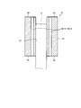
- FIG. 2 is a cross-sectional view illustrating the rotor 21 of the compressor 1 according to the embodiment.
- the rotor 21 includes a rotor core 31, a lower rotor end plate 32, and an upper rotor end plate 33.
- the rotor core 31 is formed in a substantially cylindrical shape, and is formed by laminating a plurality of steel plates made of a soft magnetic material such as a silicon steel plate, for example.
- the rotor core 31 has a lower rotor end surface 34 and an upper rotor end surface 35.
- the lower rotor end surface 34 is formed at a portion corresponding to one bottom surface of a cylinder formed by the rotor core 31, and is formed at a portion of the rotor core 31 that faces the compressor unit 5.
- the upper rotor end surface 35 is formed at a portion corresponding to the other bottom surface of the column formed by the rotor core 31, and is formed on the opposite side of the rotor core 31 from the side where the lower rotor end surface 34 is formed.
- the rotor core 31 further has a rotor shaft hole 37 and a plurality of refrigerant holes 36-1 to 36-6.
- the rotor shaft hole 37 is formed so as to overlap the central axis of the cylinder formed by the rotor core 31, and is formed so as to penetrate the lower rotor end surface 34 and the upper rotor end surface 35.
- the rotor core 31 is fixed to the shaft 3 with the shaft 3 passing through the rotor shaft hole 37.
- the plurality of refrigerant holes 36-1 to 36-6 are formed in parallel to the central axis of the rotor core 31 and are formed so as to penetrate the lower rotor end surface 34 and the upper rotor end surface 35.
- the lower rotor end plate 32 is generally formed in a disc shape.
- the lower rotor end plate 32 is in close contact with the lower rotor end surface 34 and is fixed to the rotor core 31 so as to cover the lower rotor end surface 34 of the rotor core 31.
- the lower rotor end plate 32 is disposed on the lower rotor end surface 34 side of the plurality of refrigerant holes 36-1 to 36-6 so that the plurality of refrigerant holes 36-1 to 36-6 communicate with the internal space 7. Is exposed to the internal space 7.
- the upper rotor end plate 33 is formed in a generally disc shape.
- the upper rotor end plate 33 is in close contact with the upper rotor end surface 35 and is fixed to the rotor core 31 so as to cover the upper rotor end surface 35 of the rotor core 31.
- the upper rotor end plate 33 is connected to the end on the upper rotor end surface 35 side of the plurality of refrigerant holes 36-1 to 36-6 so that the plurality of refrigerant holes 36-1 to 36-6 communicate with the internal space 7. Is exposed in the internal space 7.
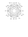
- FIG. 3 is a plan view showing the rotor core 31 of the compressor 1 of the embodiment.
- the plurality of coolant holes 36-1 to 36-6 are arranged at equal intervals around the rotor shaft hole 37, as shown in FIG.
- the rotor core 31 further has a plurality of magnet holes 41-1 to 41-6 and a plurality of rivet holes 42-1 to 42-6.
- the plurality of magnet holes 41-1 to 41-6 are formed on the outer diameter side farther from the rotor shaft hole 37 than the plurality of refrigerant holes 36-1 to 36-6, respectively. That is, the first magnet hole 41-1 of the plurality of magnet holes 41-1 to 41-6 is the first refrigerant hole 36-1 of the plurality of refrigerant holes 36-1 to 36-6. It is formed on the outer diameter side.
- the second magnet hole 41-2 of the plurality of magnet holes 41-1 to 41-6 is outside the second refrigerant hole 36-2 of the plurality of refrigerant holes 36-1 to 36-6. It is formed on the radial side.
- the third magnet hole 41-3 of the plurality of magnet holes 41-1 to 41-6 is outside the third refrigerant hole 36-3 of the plurality of refrigerant holes 36-1 to 36-6. It is formed on the radial side.
- the fourth magnet hole 41-4 of the plurality of magnet holes 41-1 to 41-6 is outside the fourth refrigerant hole 36-4 of the plurality of refrigerant holes 36-1 to 36-6. It is formed on the radial side.
- the fifth magnet hole 41-5 of the plurality of magnet holes 41-1 to 41-6 is outside the fifth refrigerant hole 36-5 of the plurality of refrigerant holes 36-1 to 36-6. It is formed on the radial side.
- the sixth magnet hole 41-6 of the plurality of magnet holes 41-1 to 41-6 is outside the sixth refrigerant hole 36-6 of the plurality of refrigerant holes 36-1 to 36-6. It is formed on the radial side.
- the plurality of rivet holes 42-1 to 42-6 are formed on the outer diameter side farther from the rotor shaft hole 37 than the plurality of refrigerant holes 36-1 to 36-6, and the plurality of magnet holes 41-1 to 41-41. It is formed on the inner diameter side closer to the rotor shaft hole 37 than ⁇ 6.
- the circumferential positions of the plurality of rivet holes 42-1 to 42-6 are the same as the circumferential positions of the plurality of refrigerant holes 36-1 to 36-6. It is formed on the outer diameter side of a region adjacent to the plurality of refrigerant holes 36-1 to 36-6 in the circumferential direction so as not to overlap.
- FIG. 4 is an enlarged plan view showing the rotor core 31 of the compressor 1 of the embodiment.
- the first magnet hole 41-1 is formed in a V shape and is formed along a curved surface that is bent so as to be convex toward the inner diameter side. That is, the first magnet hole 41-1 includes a first magnet hole portion 51, a second magnet hole portion 52, and an intermediate hole portion 53. The first magnet hole portion 51 and the second magnet hole portion 52 are connected via an intermediate hole portion 53.
- the end of the first magnet hole 51 closer to the second magnet hole 52 is closer to the rotor shaft than the end of the first magnet hole 51 farther from the second magnet hole 52.
- the hole 37 is disposed on the inner diameter side near the rotation axis.
- the end of the second magnet hole portion 52 closer to the first magnet hole portion 51 is on the inner diameter side than the end of the second magnet hole portion 52 far from the first magnet hole portion 51. Is arranged.
- the magnet holes other than the first magnet hole 41-1 are also formed in a V shape like the first magnet hole 41-1 and have an inner diameter. It is formed along a curved surface that is bent so as to be convex to the side.
- the rotor 21 further includes a plurality of permanent magnets 55.
- Each of the plurality of permanent magnets 55 is formed in a plate shape.
- the plurality of permanent magnets 55 are embedded one by one in the first magnet hole portion 51 and the second magnet hole portion 52 of the plurality of magnet holes 41-1 to 41-6, that is, the plurality of magnet holes Two pieces are embedded in 41-1 to 41-6.
- the end of the first magnet 56 closer to the second magnet 57 is arranged on the inner diameter side than the end of the first magnet 56 farther from the second magnet 57.
- the end of the second magnet 57 closer to the first magnet 56 is arranged on the inner diameter side than the end of the second magnet 57 far from the first magnet 56.
- the plurality of magnet holes 41-1 to 41-6 are closed at both ends by appropriately attaching the lower rotor end plate 32 and the upper rotor end plate 33 to the rotor core 31.
- the plurality of permanent magnets 55 are prevented from falling off the rotor core 31 by closing both ends of the plurality of magnet holes 41-1 to 41-6 with the lower rotor end plate 32 and the upper rotor end plate 33. It is fixed to the rotor core 31.
- the rotor 21 has a plurality of permanent magnets 55 embedded in a plurality of magnet holes 41-1 to 41-6 formed in a V shape, so that even if the surface area of the plurality of permanent magnets 55 is increased, the rotor 21 It can be arranged inside, and a large magnetic force can be secured.
- a magnet side inner wall surface 61 and a rotor shaft hole side inner wall surface 62 are formed in the first coolant hole 36-1.
- the magnet-side inner wall surface 61 forms a portion disposed on the outer diameter side of the inner wall surface of the first refrigerant hole 36-1, and the first magnet of the inner wall surface of the first refrigerant hole 36-1.
- a portion disposed on the side close to the use hole 41-1 is formed.
- the magnet side inner wall surface 61 is formed along a curved surface that is bent so as to be convex toward the inner diameter side. That is, the magnet side inner wall surface 61 includes a first magnet side inner wall surface portion 63, a second magnet side inner wall surface portion 64, and a magnet side intermediate inner wall surface portion 65.
- the magnet side intermediate inner wall surface portion 65 is formed between the first magnet side inner wall surface portion 63 and the second magnet side inner wall surface portion 64, and the first magnet side inner wall surface portion 63 and the second magnet side inner wall surface portion 64.
- the first magnet side inner wall surface portion 63 is formed so as to be substantially along the other plane parallel to the plane along which the first magnet hole portion 51 of the first magnet hole 41-1 is along.
- the second magnet side inner wall surface portion 64 is formed so as to be substantially along another plane parallel to the plane along which the second magnet hole portion 52 of the first magnet hole 41-1 is along.
- the rotor shaft hole side inner wall surface 62 is formed along a curved surface that is bent so as to protrude toward the inner diameter side, and the center protrudes toward the rotor shaft hole 37. That is, the rotor shaft hole side inner wall surface 62 includes a first rotor shaft hole side inner wall surface portion 66, a second rotor shaft hole side inner wall surface portion 67, and a rotor shaft hole side inner wall surface portion 68.
- the rotor shaft hole side intermediate inner wall surface portion 68 is formed between the first rotor shaft hole side inner wall surface portion 66 and the second rotor shaft hole side inner wall surface portion 67, and The second rotor shaft hole side inner wall surface portion 67 is connected via a rotor shaft hole side inner inner wall surface portion 68.
- the first rotor shaft hole side inner wall surface portion 66 is disposed on the outer diameter side of the rotor shaft hole side intermediate wall surface portion 68, and the rotor shaft hole side intermediate inner wall surface portion of the first rotor shaft hole side inner wall surface portion 66.
- the end opposite to the end adjacent to 68 is adjacent to the first magnet side inner wall surface portion 63.
- the second rotor shaft hole side inner wall surface portion 67 is disposed on the outer diameter side of the rotor shaft hole side intermediate inner wall surface portion 68, and the rotor shaft hole side intermediate inner wall surface portion of the second rotor shaft hole side inner wall surface portion 67.
- An end opposite to the end adjacent to 68 is adjacent to the second magnet side inner wall surface portion 64.
- the refrigerant holes other than the first refrigerant hole 36-1 are also arranged on the magnet-side inner wall surface 61 and the rotor shaft in the same manner as the first refrigerant hole 36-1.
- a hole-side inner wall surface 62 is formed.
- the compressor 1 is provided in a refrigeration cycle apparatus (not shown), and is used for compressing a refrigerant and circulating the refrigerant in the refrigeration cycle apparatus.
- the motor unit 6 of the compressor 1 generates a rotating magnetic field by applying a three-phase voltage to the winding 26 of the stator 22.
- the rotor 21 is rotated by the rotating magnetic field generated by the stator 22.
- the plurality of permanent magnets 55 embedded in the rotor 21 generate heat when the rotor 21 is rotated by the rotating magnetic field generated by the stator 22.
- the motor unit 6 rotates the shaft 3 as the rotor 21 rotates.
- the compressor unit 5 When the shaft 3 rotates, the compressor unit 5 sucks the low-pressure refrigerant gas through the suction pipe 11 and generates the high-pressure refrigerant gas by compressing the sucked low-pressure refrigerant gas. Supply to the muffler chamber 16 and the lower muffler chamber 17.
- the lower muffler cover 15 reduces the pressure pulsation of the high-pressure refrigerant gas supplied to the lower muffler chamber 17 and supplies the high-pressure refrigerant gas with the reduced pressure pulsation to the upper muffler chamber 16.
- the upper muffler cover 14 reduces the pressure pulsation of the high-pressure refrigerant gas supplied to the upper muffler chamber 16, and the high-pressure refrigerant gas with the reduced pressure pulsation is supplied to the compressor unit 5 and the motor unit 6 in the internal space 7. Is supplied to the space between the two through the compressed refrigerant discharge hole 18.
- the temperature of the high-pressure refrigerant gas supplied to the space between the compressor unit 5 and the motor unit 6 in the internal space 7 is lower than the temperatures of the plurality of permanent magnets 55 when the rotor 21 is rotating.
- the high-pressure refrigerant gas supplied to the space between the compressor unit 5 and the motor unit 6 in the internal space 7 passes through the plurality of refrigerant holes 36-1 to 36-6, so that the internal space 7 It is supplied to the space above the motor unit 6.
- the plurality of permanent magnets 55 are cooled when the high-pressure refrigerant gas passes through the plurality of refrigerant holes 36-1 to 36-6.
- the compressor 1 has a plurality of refrigerant holes 36-1 to 36-6 and a plurality of refrigerant holes 36-1 to 36-6 because the distance between the plurality of refrigerant holes 36-1 to 36-6 and the plurality of magnet holes 41-1 to 41-6 is short.
- the plurality of permanent magnets 55 can be cooled with the high-pressure refrigerant gas passing through ⁇ 6.
- the refrigerant supplied to the space above the motor unit 6 in the internal space 7 is discharged to a device subsequent to the compressor 1 in the refrigeration cycle device via the discharge pipe 12.
- FIG. 5 is a diagram showing a temperature distribution of the rotor core 31 of the compressor 1 of the embodiment.
- FIG. 5 shows the temperature distribution of the rotor core 31 when the compressor 1 of the embodiment is operated under the cooling rated condition.
- FIG. 6 is a diagram showing the temperature distribution of the rotor core 101 of the compressor of the comparative example.
- the rotor core 101 of the compressor of the comparative example includes a plurality of refrigerant holes 36-1 to 36-6 of the rotor core 31 of the compressor 1 of the above-described embodiment.
- the refrigerant holes 102-1 to 102-6 are replaced.
- the first refrigerant hole 102-1 disposed on the inner diameter side of the first magnet hole 41-1 has a magnet side inner wall surface 103 and a rotor shaft hole side.
- An inner wall surface 104 is formed.
- the magnet side inner wall surface 103 is formed along a curved surface that is bent so as to be convex toward the outer diameter side.
- the rotor shaft hole side inner wall surface 104 is formed along a curved surface that is bent so as to be convex toward the outer diameter side.
- other refrigerant holes different from the first refrigerant hole 102-1 are also projected to the outer diameter side, like the first refrigerant hole 102-1.
- a magnet side inner wall surface 103 along a certain curved surface and a rotor shaft hole side inner wall surface 104 along a curved surface convex toward the outer diameter side are formed.
- FIG. 6 shows the temperature distribution of the rotor core 101 when the compressor of the comparative example is operated under the same conditions as the conditions of operation of the compressor 1 of the embodiment when the temperature distribution of FIG. 5 is measured. . Comparing the temperature distribution of FIG. 5 with the temperature distribution of FIG. 6, it can be seen that the temperature on the intermediate hole portion 53 side of the first magnet 56 and the second magnet 57 is lower in the temperature distribution of FIG. 5. This is because each of the first magnet side inner wall surface portion 63 and the second magnet side inner wall surface portion 64 is formed on the side closer to the first magnet 56 and the second magnet 57.
- the maximum value of the temperature of the plurality of permanent magnets 55 is lower than the maximum value (108.5 (° C.)) of the comparative example (107.8 (° C.)). That is, FIG. 5 and FIG. 6 show that the compressor 1 of the embodiment can cool the plurality of permanent magnets 55 as compared with the compressor of the comparative example. The compressor 1 of the embodiment can reduce the adverse effect of the heat generated by the plurality of permanent magnets 55 on the motor unit 6 by cooling the plurality of permanent magnets 55 with high efficiency.
- the rotor core 31 is fixed to the shaft 3 when the shaft 3 penetrates the rotor shaft hole 37 and the shaft 3 is shrink-fitted. Therefore, stress is applied to the region between the plurality of coolant holes 36-1 to 36-6 and the rotor shaft hole 37 in the rotor core 31.
- FIG. 7 is a diagram showing the stress distribution of the rotor core 31 of the compressor 1 of the embodiment.
- FIG. 7 shows that the region of the rotor core 31 where a greater stress is applied to the shrink fit of the shaft 3 is relatively small.
- FIG. 8 is a diagram showing the stress distribution of the rotor core 101 of the compressor of the comparative example.
- the rotor core 101 of the compressor of the comparative example is fixed to the shaft 3 by shrink fitting, similarly to the rotor core 31 of the compressor 1 of the embodiment.
- FIG. 8 shows that a region where a larger stress is applied to the shrink fit of the shaft 3 in the rotor core 101 is wider than a region where a larger stress is applied to the shrink fit of the shaft 3 in the rotor core 31 of FIG. Is shown.
- FIG. 7 and FIG. 8 show that the compressor 1 of the embodiment reduces the stress concentration (stress concentration) applied to the rotor core 31 by shrink fitting of the shaft 3 as compared with the compressor of the comparative example. It shows what you can do. This is because the rotor shaft hole side inner wall surface 62 of the compressor 1 of the embodiment is formed along a curved surface that is bent so as to be convex toward the inner diameter side. That is, in the compressor 1 of the embodiment, since the region between the plurality of refrigerant holes 36-1 to 36-6 and the rotor shaft hole 37 is larger in the radial direction than the comparative example, the strength of the rotor core 31 of the embodiment Becomes larger. Although the stress concentration is weak and is likely to occur at locations where the shape changes, the strength of the rotor core 31 of the example is higher than that of the comparative example, and it is considered that the stress concentration is less likely to occur than the comparative example.
- the compressor 1 includes a rotor 21, a stator 22, a compressor unit 5, and a container 2.
- the rotor 21 is fixed to the shaft 3.
- the stator 22 rotates the rotor 21 around the rotation axis.
- the compressor unit 5 compresses the refrigerant as the shaft 3 rotates.
- the container 2 forms an internal space 7 in which the rotor 21, the stator 22, and the compressor unit 5 are stored.
- the rotor 21 includes a rotor core 31 in which a first refrigerant hole 36-1 is formed, a first magnet 56 embedded in the rotor core 31, and a second magnet 57 embedded in the rotor core 31.
- the magnet side inner wall surface 61 formed on the outer diameter side far from the rotation axis of the shaft 3 includes a first magnet side inner wall surface portion 63 and a second magnet side inner wall surface. A portion 64 and a magnet side intermediate inner wall surface portion 65 are included.
- the first magnet side inner wall surface portion 63 is formed on the side close to the first magnet 56.
- the second magnet side inner wall surface portion 64 is formed on the side close to the second magnet 57.
- the magnet side intermediate inner wall surface portion 65 is formed between the first magnet side inner wall surface portion 63 and the second magnet side inner wall surface portion 64.
- the magnet side intermediate inner wall surface portion 65 is formed on the inner diameter side closer to the rotation axis of the shaft 3 than the first magnet side inner wall surface portion 63 and the second magnet side inner wall surface portion 64.
- the distance between the plurality of refrigerant holes 36-1 to 36-6 and the plurality of permanent magnets 55 is short, and the refrigerant passes through the plurality of refrigerant holes 36-1 to 36-6.
- the plurality of permanent magnets 55 provided on the rotor 21 can be cooled.
- the first magnet 56 of the compressor 1 is arranged so that one end closer to the second magnet 57 is closer to the rotation axis of the shaft 3 than the other end. It arrange
- the compressor 1 of the embodiment when the first magnet 56 and the second magnet 57 of the plurality of permanent magnets 55 are arranged in a V shape, the refrigerant passing through the first refrigerant hole 36-1 The first magnet 56 and the second magnet 57 can be further cooled.
- first magnet side inner wall surface portion 63 of the compressor 1 of the embodiment is along another plane parallel to the plane along which the first magnet 56 extends
- the second magnet side inner wall surface portion 64 is the second magnet 57.
- first refrigerant hole 36- The first magnet 56 and the second magnet 57 can be further cooled by the refrigerant passing through 1.
- the rotor core 31 of the compressor 1 of the embodiment further has a rotor shaft hole 37 through which the shaft 3 passes.
- the rotor shaft hole side inner wall surface 62 formed on the inner diameter side near the rotation axis of the shaft 3 is composed of the first rotor shaft hole side inner wall surface portion 66 and the second rotor.
- a shaft hole side inner wall surface portion 67 and a rotor shaft hole side intermediate inner wall surface portion 68 are included.
- the rotor shaft hole side intermediate inner wall surface portion 68 is formed between the first rotor shaft hole side inner wall surface portion 66 and the second rotor shaft hole side inner wall surface portion 67.
- the first rotor shaft hole side inner wall surface portion 66 is adjacent to the first magnet side inner wall surface portion 63.
- the second rotor shaft hole side inner wall surface portion 67 is adjacent to the second magnet side inner wall surface portion 64.
- the rotor shaft hole side intermediate inner wall surface portion 68 is formed on the inner diameter side closer to the rotor shaft hole 37 than the first rotor shaft hole side inner wall surface portion 66 and the second rotor shaft hole side inner wall surface portion 67.
- the region between the plurality of refrigerant holes 36-1 to 36-6 and the rotor shaft hole 37 is increased in the radial direction, and the strength of the rotor core 31 is not reduced. Decrease in fastening force between the shaft 3 and the shaft 3 can be suppressed, and the rotor core 31 can be appropriately fixed to the shaft 3.
- the rotor shaft hole side inner wall surface 62 of the compressor 1 of the embodiment is formed along a curved surface that is bent so as to be convex toward the inner diameter side, but is formed so as not to be convex toward the inner diameter side. May be.
- the compressor 1 is provided in the rotor 21 with the refrigerant passing through the plurality of refrigerant holes 36-1 to 36-6 by forming the magnet-side inner wall surface 61 so as to protrude toward the inner diameter side.
- the plurality of permanent magnets 55 can be cooled with high efficiency.
- the magnet-side inner wall surface 61 of the compressor 1 of the embodiment is formed along a curved surface that is bent so as to be convex toward the inner diameter side, but is formed so as not to be convex toward the inner diameter side. Also good.
- the compressor 1 is formed such that the inner surface 62 on the rotor shaft hole side is convex toward the inner diameter side, so that the space between the plurality of coolant holes 36-1 to 36-6 and the rotor shaft hole 37 This area increases in the radial direction, and the strength of the rotor core 31 can be increased.
- the compressor part 5 of the compressor 1 of the above-described embodiment is formed of a rotary compressor, it may be replaced with another compressor part formed by a mechanism different from the rotary compressor.
- a scroll compressor is exemplified.
- the embodiment has been described above, but the embodiment is not limited by the above-described content.
- the above-described constituent elements include those that can be easily assumed by those skilled in the art, those that are substantially the same, and those in a so-called equivalent range.
- the above-described components can be appropriately combined.
- at least one of various omissions, substitutions, and changes of the components can be made without departing from the scope of the embodiments.
Landscapes
- Engineering & Computer Science (AREA)
- Power Engineering (AREA)
- Iron Core Of Rotating Electric Machines (AREA)
- Permanent Field Magnets Of Synchronous Machinery (AREA)
Abstract
ロータ(21)は、第1冷媒用孔(36-1)が形成されるロータコア(31)と、ロータコア(31)に埋め込まれる第1磁石(56)と、ロータコア(31)に埋め込まれる第2磁石(57)とを備えている。第1冷媒用孔(36-1)の内壁面のうちの外径側に形成される磁石側内壁面(61)は、第1磁石側内壁面部分(63)と第2磁石側内壁面部分(64)と磁石側中間内壁面部分(65)とを含んでいる。第1磁石側内壁面部分(63)は、第1磁石(56)に近い側に形成されている。第2磁石側内壁面部分(64)は、第2磁石(57)に近い側に形成されている。磁石側中間内壁面部分(65)は、第1磁石側内壁面部分(63)と第2磁石側内壁面部分(64)との間に形成されている。磁石側中間内壁面部分(65)は、第1磁石側内壁面部分(63)と第2磁石側内壁面部分(64)とよりシャフト(3)の回転軸に近い側に形成されている。
Description
本開示の技術は、圧縮機に関する。
圧縮機部とモータ部とが密閉容器の内部に格納される密閉型の圧縮機が知られている。モータ部は、永久磁石が埋め込まれるロータと、回転磁界を生成することによりロータを回転させるステータとを備え、ロータに固定されるシャフトを介して圧縮機部に回転動力を伝達する。圧縮機部は、モータから伝達される回転動力を用いて、冷媒を圧縮する(特許文献1~6参照)。
ロータに埋め込まれる永久磁石は、ステータにより生成される回転磁界によりロータが回転するときに、例えばステータからの磁束により永久磁石に渦電流が生じて発熱する。永久磁石の発熱は永久磁石を減磁させる原因となるなど、モータ部に悪影響を及ぼすという問題がある。
開示の技術は、かかる点に鑑みてなされたものであって、モータ部に設けられる永久磁石を冷却する圧縮機を提供することを目的とする。
開示の態様では、圧縮機は、ロータとステータと圧縮機部と容器とを備えている。前記ロータは、シャフトに固定されている。前記ステータは、回転軸を中心に前記ロータを回転させる。前記圧縮機部は、前記シャフトが回転することにより冷媒を圧縮する。前記容器は、前記ロータと前記ステータと前記圧縮機部とが格納される内部空間を形成している。前記ロータは、冷媒用孔が形成されるロータコアと、前記ロータコアに埋め込まれる第1磁石と、前記ロータコアに埋め込まれる第2磁石とを有している。前記冷媒用孔の内壁面のうちの前記回転軸から遠い側に形成される磁石側内壁面は、第1磁石側内壁面部分と第2磁石側内壁面部分と磁石側中間内壁面部分とを含んでいる。前記磁石側中間内壁面部分は、前記第1磁石側内壁面部分と前記第2磁石側内壁面部分との間に形成されている。前記第1磁石側内壁面部分は、前記第1磁石に近い側に形成されている。前記第2磁石側内壁面部分は、前記第2磁石に近い側に形成されている。前記磁石側中間内壁面部分は、前記第1磁石側内壁面部分と前記第2磁石側内壁面部分とより前記回転軸に近い側に形成されている。
開示の圧縮機は、モータ部に設けられる永久磁石を冷却することができる。
以下に、本願が開示する実施形態にかかる圧縮機について、図面を参照して説明する。なお、以下の記載により本開示の技術が限定されるものではない。また、以下の記載においては、同一の構成要素に同一の符号を付与し、重複する説明を省略する。
図1は、実施例の圧縮機1を示す縦断面図である。圧縮機1は、図1に示されているように、容器2とシャフト3と圧縮機部5とモータ部6とを備えている。容器2は、密閉された内部空間7を形成している。内部空間7は、概ね円柱状に形成されている。容器2は、水平面に縦置きされたときに、内部空間7の円柱の中心軸が鉛直方向に平行になるように、形成されている。容器2には、内部空間7の下部に油溜め8が形成されている。油溜め8には、圧縮機部5を潤滑させる冷凍機油が貯留される。容器2には、冷媒を吸入する吸入管11と圧縮された冷媒を吐出する吐出管12とが接続されている。シャフト3は、棒状に形成され、一端が油溜め8に配置されるように、容器2の内部空間7に配置されている。シャフト3は、内部空間7が形成する円柱の中心軸に平行である回転軸を中心に回転可能に容器2に支持されている。シャフト3は、回転することにより、圧縮機部5の内部にあるローラを回転させる。ローラが回転することで冷媒が圧縮される。また、シャフト3が回転すると油溜め8に貯留される冷凍機油が図示しないシャフト3の内部を通り圧縮機部5に供給される。
圧縮機部5は、内部空間7の下部に配置され、油溜め8の上方に配置されている。圧縮機1は、さらに、上マフラーカバー14と下マフラーカバー15とを備えている。上マフラーカバー14は、内部空間7のうちの圧縮機部5の上部に配置されている。上マフラーカバー14は、内部に上マフラー室16を形成している。下マフラーカバー15は、内部空間7のうちの圧縮機部5の下部に配置され、油溜め8の上部に配置されている。下マフラーカバー15は、内部に下マフラー室17を形成している。下マフラー室17は、圧縮機部5に形成されている連通路(図示されていない)を介して上マフラー室16に連通している。上マフラーカバー14とシャフト3との間には、圧縮冷媒吐出孔18が形成され、上マフラー室16は、圧縮冷媒吐出孔18を介して内部空間7に連通している。
圧縮機部5は、いわゆるロータリー型の圧縮機であり、シャフト3が回転することにより吸入管11から供給される冷媒を圧縮し、その圧縮された冷媒を上マフラー室16と下マフラー室17とに供給する。その冷媒は、冷凍機油と相溶性を有している。モータ部6は、内部空間7のうちの圧縮機部5の上部に配置されている。モータ部6は、ロータ21とステータ22とを備えている。ロータ21は、シャフト3に固定されている。ステータ22は、概ね円筒形に形成され、ロータ21を囲むように配置され、容器2に固定されている。ステータ22は、巻き線26を備えている。ステータ22は、巻き線26に単相または三相電圧が適切に印加されることにより、回転磁界を生成し、ロータ21を回転させる。
[ロータ21]
図2は、実施例の圧縮機1のロータ21を示す断面図である。ロータ21は、図2に示されているように、ロータコア31と下側ロータ端板32と上側ロータ端板33とを備えている。ロータコア31は、概ね円柱状に形成され、たとえば、ケイ素鋼板のような軟磁性体で形成された複数の鋼板が積層されて形成されている。ロータコア31は、下側ロータ端面34と上側ロータ端面35とが形成されている。下側ロータ端面34は、ロータコア31が形成する円柱の一方の底面に対応する部位に形成され、ロータコア31のうちの圧縮機部5に対向する部位に形成されている。上側ロータ端面35は、ロータコア31が形成する円柱の他方の底面に対応する部位に形成され、ロータコア31のうちの下側ロータ端面34が形成されている側の反対側に形成されている。
図2は、実施例の圧縮機1のロータ21を示す断面図である。ロータ21は、図2に示されているように、ロータコア31と下側ロータ端板32と上側ロータ端板33とを備えている。ロータコア31は、概ね円柱状に形成され、たとえば、ケイ素鋼板のような軟磁性体で形成された複数の鋼板が積層されて形成されている。ロータコア31は、下側ロータ端面34と上側ロータ端面35とが形成されている。下側ロータ端面34は、ロータコア31が形成する円柱の一方の底面に対応する部位に形成され、ロータコア31のうちの圧縮機部5に対向する部位に形成されている。上側ロータ端面35は、ロータコア31が形成する円柱の他方の底面に対応する部位に形成され、ロータコア31のうちの下側ロータ端面34が形成されている側の反対側に形成されている。
ロータコア31は、ロータ軸孔37と複数の冷媒用孔36-1~36-6とがさらに形成されている。ロータ軸孔37は、ロータコア31が形成する円柱の中心軸に重なるように形成され、下側ロータ端面34と上側ロータ端面35とを貫通するように形成されている。ロータコア31は、シャフト3がロータ軸孔37に貫通した状態で、シャフト3に固定されている。複数の冷媒用孔36-1~36-6は、ロータコア31の中心軸に平行に形成され、下側ロータ端面34と上側ロータ端面35とを貫通するように、形成されている。
下側ロータ端板32は、概ね円板状に形成されている。下側ロータ端板32は、ロータコア31の下側ロータ端面34を覆うように、下側ロータ端面34に密着し、ロータコア31に固定されている。下側ロータ端板32は、複数の冷媒用孔36-1~36-6が内部空間7に連通するように、複数の冷媒用孔36-1~36-6の下側ロータ端面34の側の端を内部空間7に露出させている。上側ロータ端板33は、概ね円板状に形成されている。上側ロータ端板33は、ロータコア31の上側ロータ端面35を覆うように、上側ロータ端面35に密着し、ロータコア31に固定されている。上側ロータ端板33は、複数の冷媒用孔36-1~36-6が内部空間7に連通するように、複数の冷媒用孔36-1~36-6の上側ロータ端面35の側の端を内部空間7に露出させている。
図3は、実施例の圧縮機1のロータコア31を示す平面図である。複数の冷媒用孔36-1~36-6は、図3に示されているように、ロータ軸孔37の周りに等間隔に配置されている。ロータコア31は、さらに、複数の磁石用孔41-1~41-6と複数のリベット用孔42-1~42-6とが形成されている。複数の磁石用孔41-1~41-6は、複数の冷媒用孔36-1~36-6よりロータ軸孔37から遠い外径側にそれぞれ形成されている。すなわち、複数の磁石用孔41-1~41-6のうちの第1磁石用孔41-1は、複数の冷媒用孔36-1~36-6のうちの第1冷媒用孔36-1の外径側に形成されている。複数の磁石用孔41-1~41-6のうちの第2磁石用孔41-2は、複数の冷媒用孔36-1~36-6のうちの第2冷媒用孔36-2の外径側に形成されている。複数の磁石用孔41-1~41-6のうちの第3磁石用孔41-3は、複数の冷媒用孔36-1~36-6のうちの第3冷媒用孔36-3の外径側に形成されている。複数の磁石用孔41-1~41-6のうちの第4磁石用孔41-4は、複数の冷媒用孔36-1~36-6のうちの第4冷媒用孔36-4の外径側に形成されている。複数の磁石用孔41-1~41-6のうちの第5磁石用孔41-5は、複数の冷媒用孔36-1~36-6のうちの第5冷媒用孔36-5の外径側に形成されている。複数の磁石用孔41-1~41-6のうちの第6磁石用孔41-6は、複数の冷媒用孔36-1~36-6のうちの第6冷媒用孔36-6の外径側に形成されている。
複数のリベット用孔42-1~42-6は、複数の冷媒用孔36-1~36-6よりロータ軸孔37から遠い外径側に形成され、複数の磁石用孔41-1~41-6よりロータ軸孔37に近い内径側に形成されている。複数のリベット用孔42-1~42-6は、複数のリベット用孔42-1~42-6の周方向の位置が複数の冷媒用孔36-1~36-6の周方向の位置と重ならないように、複数の冷媒用孔36-1~36-6と周方向に隣接する領域の外径側に形成されている。
図4は、実施例の圧縮機1のロータコア31を示す平面拡大図である。第1磁石用孔41-1は、図4に示されているように、V字形状に形成され、内径側に凸であるように屈曲している曲面に沿うように形成されている。すなわち、第1磁石用孔41-1は、第1磁石用孔部分51と第2磁石用孔部分52と中間孔部分53とを含んでいる。第1磁石用孔部分51と第2磁石用孔部分52とは、中間孔部分53を介して繋がっている。第1磁石用孔部分51のうちの第2磁石用孔部分52に近い側の端は、第1磁石用孔部分51のうちの第2磁石用孔部分52から遠い側の端より、ロータ軸孔37の回転軸に近い内径側に配置されている。第2磁石用孔部分52のうちの第1磁石用孔部分51に近い側の端は、第2磁石用孔部分52のうちの第1磁石用孔部分51から遠い側の端より、内径側に配置されている。
複数の磁石用孔41-1~41-6のうちの第1磁石用孔41-1以外の磁石用孔も、第1磁石用孔41-1と同様に、V字形状に形成され、内径側に凸であるように屈曲している曲面に沿うように形成されている。
ロータ21は、複数の永久磁石55をさらに備えている。複数の永久磁石55は、それぞれ、板状に形成されている。複数の永久磁石55は、複数の磁石用孔41-1~41-6の第1磁石用孔部分51と第2磁石用孔部分52とに1個ずつ埋め込まれ、すなわち、複数の磁石用孔41-1~41-6に2個ずつ埋め込まれている。第1磁石56のうちの第2磁石57に近い側の端は、第1磁石56のうちの第2磁石57から遠い側の端より内径側に配置されている。第2磁石57のうちの第1磁石56に近い側の端は、第2磁石57のうちの第1磁石56から遠い側の端より内径側に配置されている。
複数の磁石用孔41-1~41-6は、下側ロータ端板32と上側ロータ端板33とがロータコア31に適切に取り付けられることにより、両端が閉塞される。複数の永久磁石55は、複数の磁石用孔41-1~41-6の両端が下側ロータ端板32と上側ロータ端板33とで閉塞されることにより、ロータコア31から脱落しないように、ロータコア31に固定されている。ロータ21は、V字形状に形成される複数の磁石用孔41-1~41-6に複数の永久磁石55が埋め込まれることにより、複数の永久磁石55の表面積を大きくしてもロータ21の内部に配置することができ、大きい磁力を確保することができる。
第1冷媒用孔36-1には、磁石側内壁面61とロータ軸孔側内壁面62とが形成されている。磁石側内壁面61は、第1冷媒用孔36-1の内壁面のうちの外径側に配置される部分を形成し、第1冷媒用孔36-1の内壁面のうちの第1磁石用孔41-1に近い側に配置される部分を形成している。
磁石側内壁面61は、内径側に凸であるように屈曲している曲面に沿うように形成されている。すなわち、磁石側内壁面61は、第1磁石側内壁面部分63と第2磁石側内壁面部分64と磁石側中間内壁面部分65とを含んでいる。磁石側中間内壁面部分65は、第1磁石側内壁面部分63と第2磁石側内壁面部分64との間に形成され、第1磁石側内壁面部分63と第2磁石側内壁面部分64とは、磁石側中間内壁面部分65を介して繋がっている。第1磁石側内壁面部分63は、第1磁石用孔41-1の第1磁石用孔部分51が沿う平面に平行である他の平面に概ね沿うように形成されている。第2磁石側内壁面部分64は、第1磁石用孔41-1の第2磁石用孔部分52が沿う平面に平行である他の平面に概ね沿うように形成されている。
ロータ軸孔側内壁面62は、内径側に凸であるように屈曲している曲面に沿うように形成され、中央がロータ軸孔37に向かって突出している。すなわち、ロータ軸孔側内壁面62は、第1ロータ軸孔側内壁面部分66と第2ロータ軸孔側内壁面部分67とロータ軸孔側中間内壁面部分68とを含んでいる。ロータ軸孔側中間内壁面部分68は、第1ロータ軸孔側内壁面部分66と第2ロータ軸孔側内壁面部分67との間に形成され、第1ロータ軸孔側内壁面部分66と第2ロータ軸孔側内壁面部分67とは、ロータ軸孔側中間内壁面部分68を介して繋がっている。第1ロータ軸孔側内壁面部分66は、ロータ軸孔側中間内壁面部分68より外径側に配置され、第1ロータ軸孔側内壁面部分66のうちのロータ軸孔側中間内壁面部分68に隣接する端の反対側の端が第1磁石側内壁面部分63に隣接している。第2ロータ軸孔側内壁面部分67は、ロータ軸孔側中間内壁面部分68より外径側に配置され、第2ロータ軸孔側内壁面部分67のうちのロータ軸孔側中間内壁面部分68に隣接する端の反対側の端が第2磁石側内壁面部分64に隣接している。
複数の冷媒用孔36-1~36-6のうちの第1冷媒用孔36-1以外の冷媒用孔も、第1冷媒用孔36-1と同様に、磁石側内壁面61とロータ軸孔側内壁面62とが形成されている。
[圧縮機1の動作]
圧縮機1は、図示しない冷凍サイクル装置に設けられ、冷媒を圧縮して、冷凍サイクル装置に冷媒を循環させることに利用される。圧縮機1のモータ部6は、ステータ22の巻き線26に三相電圧が印加されることにより、回転磁界を発生させる。ロータ21は、ステータ22により生成された回転磁界により回転する。ロータ21に埋め込まれた複数の永久磁石55は、ステータ22により生成される回転磁界によりロータ21が回転するときに、発熱する。モータ部6は、ロータ21が回転することにより、シャフト3を回転させる。
圧縮機1は、図示しない冷凍サイクル装置に設けられ、冷媒を圧縮して、冷凍サイクル装置に冷媒を循環させることに利用される。圧縮機1のモータ部6は、ステータ22の巻き線26に三相電圧が印加されることにより、回転磁界を発生させる。ロータ21は、ステータ22により生成された回転磁界により回転する。ロータ21に埋め込まれた複数の永久磁石55は、ステータ22により生成される回転磁界によりロータ21が回転するときに、発熱する。モータ部6は、ロータ21が回転することにより、シャフト3を回転させる。
圧縮機部5は、シャフト3が回転すると、吸入管11を介して低圧冷媒ガスを吸入し、その吸入された低圧冷媒ガスを圧縮することにより高圧冷媒ガスを生成し、その高圧冷媒ガスを上マフラー室16と下マフラー室17とに供給する。下マフラーカバー15は、下マフラー室17に供給された高圧冷媒ガスの圧力の脈動を低減し、圧力脈動が低減された高圧冷媒ガスを上マフラー室16に供給する。上マフラーカバー14は、上マフラー室16に供給された高圧冷媒ガスの圧力の脈動を低減し、圧力脈動が低減された高圧冷媒ガスを内部空間7のうちの圧縮機部5とモータ部6との間の空間に圧縮冷媒吐出孔18を介して供給する。内部空間7のうちの圧縮機部5とモータ部6との間の空間に供給された高圧冷媒ガスの温度は、ロータ21が回転しているときの複数の永久磁石55の温度より低い。
内部空間7のうちの圧縮機部5とモータ部6との間の空間に供給された高圧冷媒ガスは、複数の冷媒用孔36-1~36-6を通過することにより、内部空間7のうちのモータ部6より上の空間に供給される。複数の永久磁石55は、複数の冷媒用孔36-1~36-6を高圧冷媒ガスが通過することにより冷却される。圧縮機1は、複数の冷媒用孔36-1~36-6と複数の磁石用孔41-1~41-6との間の距離が近いことにより、複数の冷媒用孔36-1~36-6を通過する高圧冷媒ガスで複数の永久磁石55を冷却することができる。内部空間7のうちのモータ部6より上の空間に供給された冷媒は、吐出管12を介して冷凍サイクル装置のうちの圧縮機1の後段の装置に吐出される。
図5は、実施例の圧縮機1のロータコア31の温度分布を示す図である。図5は、実施例の圧縮機1が冷房定格条件で運転されたときのロータコア31の温度分布を示している。
図6は、比較例の圧縮機のロータコア101の温度分布を示す図である。比較例の圧縮機のロータコア101は、図6に示されているように、既述の実施例の圧縮機1のロータコア31の複数の冷媒用孔36-1~36-6が他の複数の冷媒用孔102-1~102-6に置換されている。複数の冷媒用孔102-1~102-6のうちの第1磁石用孔41-1の内径側に配置される第1冷媒用孔102-1は、磁石側内壁面103とロータ軸孔側内壁面104とが形成されている。磁石側内壁面103は、外径側に凸であるように屈曲している曲面に沿うように形成されている。ロータ軸孔側内壁面104は、外径側に凸であるように屈曲している曲面に沿うように形成されている。複数の冷媒用孔102-1~102-6のうちの第1冷媒用孔102-1と異なる他の冷媒用孔も、第1冷媒用孔102-1と同様に、外径側に凸である曲面に沿う磁石側内壁面103と、外径側に凸である曲面に沿うロータ軸孔側内壁面104とが形成されている。
図6は、図5の温度分布が計測されたときに実施例の圧縮機1が運転された条件と同じ条件で比較例の圧縮機が運転されたときのロータコア101の温度分布を示している。図5の温度分布と図6の温度分布とを比較すると、図5の温度分布では、第1磁石56と第2磁石57との中間孔部分53側の温度が下がっていることがわかる。これは、第1磁石側内壁面部分63と第2磁石側内壁面部分64とのそれぞれが、第1磁石56と第2磁石57とに近い側に形成されていることによる。また、複数の永久磁石55の温度の最大値は、実施例の最大値(107.8(℃))が比較例の最大値(108.5(℃))よりも下がっている。すなわち、図5と図6とは、実施例の圧縮機1が比較例の圧縮機に比較して、複数の永久磁石55を冷却することができることを示している。実施例の圧縮機1は、複数の永久磁石55を高効率に冷却することにより、複数の永久磁石55の発熱がモータ部6に及ぼす悪影響を低減することができる。
ロータコア31は、シャフト3がロータ軸孔37に貫通してシャフト3が焼嵌めされることにより、シャフト3に固定されている。このため、ロータコア31のうちの複数の冷媒用孔36-1~36-6とロータ軸孔37との間の領域には、応力が加わっている。
図7は、実施例の圧縮機1のロータコア31の応力分布を示す図である。図7は、ロータコア31のうちのシャフト3の焼嵌めにより大きい応力が加わる領域が比較的小さいことを示している。図8は、比較例の圧縮機のロータコア101の応力分布を示す図である。比較例の圧縮機のロータコア101は、実施例の圧縮機1のロータコア31と同様に、焼嵌めによりシャフト3に固定されている。図8は、ロータコア101のうちのシャフト3の焼嵌めにより大きい応力が加わる領域が、図7のロータコア31のうちのシャフト3の焼嵌めにより大きい応力が加わる領域に比較して、広範囲であることを示している。すなわち、図7と図8とは、実施例の圧縮機1が、比較例の圧縮機に比較して、シャフト3の焼嵌めによりロータコア31に加わる応力の集中(応力集中)を低減することができることを示している。これは、実施例の圧縮機1のロータ軸孔側内壁面62は、内径側に凸であるように屈曲している曲面に沿うように形成されていることによる。すなわち、実施例の圧縮機1は比較例と比べて複数の冷媒用孔36-1~36-6とロータ軸孔37との間の領域が径方向に大きいため、実施例のロータコア31の強度が大きくなる。応力集中は強度が弱く形状が変化する箇所に生じやすいが、実施例のロータコア31は比較例のものよりも強度が大きいため、比較例よりも応力集中が生じにくいと考えられる。
[実施例の圧縮機1の効果]
実施例の圧縮機1は、ロータ21とステータ22と圧縮機部5と容器2とを備えている。ロータ21は、シャフト3に固定されている。ステータ22は、回転軸を中心にロータ21を回転させる。圧縮機部5は、シャフト3が回転することにより冷媒を圧縮する。容器2は、ロータ21とステータ22と圧縮機部5とが格納される内部空間7を形成している。ロータ21は、第1冷媒用孔36-1が形成されるロータコア31と、ロータコア31に埋め込まれる第1磁石56と、ロータコア31に埋め込まれる第2磁石57とを備えている。第1冷媒用孔36-1の内壁面のうちのシャフト3の回転軸から遠い外径側に形成される磁石側内壁面61は、第1磁石側内壁面部分63と第2磁石側内壁面部分64と磁石側中間内壁面部分65とを含んでいる。第1磁石側内壁面部分63は、第1磁石56に近い側に形成されている。第2磁石側内壁面部分64は、第2磁石57に近い側に形成されている。磁石側中間内壁面部分65は、第1磁石側内壁面部分63と第2磁石側内壁面部分64との間に形成されている。磁石側中間内壁面部分65は、第1磁石側内壁面部分63と第2磁石側内壁面部分64とよりシャフト3の回転軸に近い内径側に形成されている。実施例の圧縮機1は、複数の冷媒用孔36-1~36-6と複数の永久磁石55との間の距離が短く、複数の冷媒用孔36-1~36-6を通過する冷媒により、ロータ21に設けられる複数の永久磁石55を冷却することができる。
実施例の圧縮機1は、ロータ21とステータ22と圧縮機部5と容器2とを備えている。ロータ21は、シャフト3に固定されている。ステータ22は、回転軸を中心にロータ21を回転させる。圧縮機部5は、シャフト3が回転することにより冷媒を圧縮する。容器2は、ロータ21とステータ22と圧縮機部5とが格納される内部空間7を形成している。ロータ21は、第1冷媒用孔36-1が形成されるロータコア31と、ロータコア31に埋め込まれる第1磁石56と、ロータコア31に埋め込まれる第2磁石57とを備えている。第1冷媒用孔36-1の内壁面のうちのシャフト3の回転軸から遠い外径側に形成される磁石側内壁面61は、第1磁石側内壁面部分63と第2磁石側内壁面部分64と磁石側中間内壁面部分65とを含んでいる。第1磁石側内壁面部分63は、第1磁石56に近い側に形成されている。第2磁石側内壁面部分64は、第2磁石57に近い側に形成されている。磁石側中間内壁面部分65は、第1磁石側内壁面部分63と第2磁石側内壁面部分64との間に形成されている。磁石側中間内壁面部分65は、第1磁石側内壁面部分63と第2磁石側内壁面部分64とよりシャフト3の回転軸に近い内径側に形成されている。実施例の圧縮機1は、複数の冷媒用孔36-1~36-6と複数の永久磁石55との間の距離が短く、複数の冷媒用孔36-1~36-6を通過する冷媒により、ロータ21に設けられる複数の永久磁石55を冷却することができる。
また、実施例の圧縮機1の第1磁石56は、第2磁石57に近い側の一端が他端よりシャフト3の回転軸に近くなるように、配置され、第2磁石57は、第1磁石56に近い側の一端が他端よりシャフト3の回転軸に近くなるように、配置されている。実施例の圧縮機1は、複数の永久磁石55の第1磁石56と第2磁石57とがV字形状に配置されているときに、第1冷媒用孔36-1を通過する冷媒により、第1磁石56と第2磁石57とをより冷却することができる。
また、実施例の圧縮機1の第1磁石側内壁面部分63は、第1磁石56が沿う平面に平行である他の平面に沿い、第2磁石側内壁面部分64は、第2磁石57が沿う平面に平行である他の平面に沿っている。実施例の圧縮機1は、第1磁石側内壁面部分63と第2磁石側内壁面部分64とが第1磁石56と第2磁石57とにそれぞれ沿うときに、第1冷媒用孔36-1を通過する冷媒により、第1磁石56と第2磁石57とをより冷却することができる。
また、実施例の圧縮機1のロータコア31は、シャフト3が貫通するロータ軸孔37がさらに形成されている。第1冷媒用孔36-1の内壁面のうちのシャフト3の回転軸に近い内径側に形成されるロータ軸孔側内壁面62は、第1ロータ軸孔側内壁面部分66と第2ロータ軸孔側内壁面部分67とロータ軸孔側中間内壁面部分68とを含んでいる。ロータ軸孔側中間内壁面部分68は、第1ロータ軸孔側内壁面部分66と第2ロータ軸孔側内壁面部分67との間に形成されている。第1ロータ軸孔側内壁面部分66は、第1磁石側内壁面部分63に隣接している。第2ロータ軸孔側内壁面部分67は、第2磁石側内壁面部分64に隣接している。ロータ軸孔側中間内壁面部分68は、第1ロータ軸孔側内壁面部分66と第2ロータ軸孔側内壁面部分67とよりロータ軸孔37に近い内径側に形成されている。実施例の圧縮機1は、複数の冷媒用孔36-1~36-6とロータ軸孔37との間の領域が径方向に大きくなり、ロータコア31の強度が低下することがなく、ロータコア31とシャフト3との間の締結力の低下を抑制することができ、ロータコア31をシャフト3に適切に固定することができる。
ところで、実施例の圧縮機1のロータ軸孔側内壁面62は、内径側に凸であるように屈曲している曲面に沿うように形成されているが、内径側に凸にならないように形成されてもよい。この場合、圧縮機1は、磁石側内壁面61が内径側に凸であるように形成されることにより、複数の冷媒用孔36-1~36-6を通過する冷媒により、ロータ21に設けられる複数の永久磁石55を高効率に冷却することができる。
ところで、実施例の圧縮機1の磁石側内壁面61は、内径側に凸であるように屈曲している曲面に沿うように形成されているが、内径側に凸にならないように形成されてもよい。この場合、圧縮機1は、ロータ軸孔側内壁面62が内径側に凸であるように形成されることにより、複数の冷媒用孔36-1~36-6とロータ軸孔37との間の領域が径方向に大きくなり、ロータコア31の強度を高めることができる。
ところで、既述の実施例の圧縮機1の圧縮機部5は、ロータリー圧縮機から形成されているが、ロータリー圧縮機と異なる機構から形成される他の圧縮機部に置換されてもよい。その機構としては、スクロール圧縮機が例示される。
以上、実施例を説明したが、前述した内容により実施例が限定されるものではない。また、前述した構成要素には、当業者が容易に想定できるもの、実質的に同一のもの、いわゆる均等の範囲のものが含まれる。さらに、前述した構成要素は適宜組み合わせることが可能である。さらに、実施例の要旨を逸脱しない範囲で構成要素の種々の省略、置換及び変更のうち少なくとも1つを行うことができる。
1 :圧縮機
2 :容器
3 :シャフト
5 :圧縮機部
6 :モータ部
21 :ロータ
22 :ステータ
31 :ロータコア
36-1~36-6:複数の冷媒用孔
37 :ロータ軸孔
41-1~41-6:複数の磁石用孔
55 :複数の永久磁石
56 :第1磁石
57 :第2磁石
61 :磁石側内壁面
62 :ロータ軸孔側内壁面
63 :第1磁石側内壁面部分
64 :第2磁石側内壁面部分
65 :磁石側中間内壁面部分
66 :第1ロータ軸孔側内壁面部分
67 :第2ロータ軸孔側内壁面部分
68 :ロータ軸孔側中間内壁面部分
2 :容器
3 :シャフト
5 :圧縮機部
6 :モータ部
21 :ロータ
22 :ステータ
31 :ロータコア
36-1~36-6:複数の冷媒用孔
37 :ロータ軸孔
41-1~41-6:複数の磁石用孔
55 :複数の永久磁石
56 :第1磁石
57 :第2磁石
61 :磁石側内壁面
62 :ロータ軸孔側内壁面
63 :第1磁石側内壁面部分
64 :第2磁石側内壁面部分
65 :磁石側中間内壁面部分
66 :第1ロータ軸孔側内壁面部分
67 :第2ロータ軸孔側内壁面部分
68 :ロータ軸孔側中間内壁面部分
Claims (5)
- シャフトに固定されるロータと、
回転軸を中心に前記ロータを回転させるステータと、
前記シャフトが回転することにより冷媒を圧縮する圧縮機部と、
前記ロータと前記ステータと前記圧縮機部とが格納される内部空間を形成する容器とを備え、
前記ロータは、
冷媒用孔が形成されるロータコアと、
前記ロータコアに埋め込まれる第1磁石と、
前記ロータコアに埋め込まれる第2磁石とを有し、
前記冷媒用孔の内壁面のうちの前記回転軸から遠い側に形成される磁石側内壁面は、
前記第1磁石に近い側に形成される第1磁石側内壁面部分と、
前記第2磁石に近い側に形成される第2磁石側内壁面部分と、
前記第1磁石側内壁面部分と前記第2磁石側内壁面部分との間に形成される磁石側中間内壁面部分とを含み、
前記磁石側中間内壁面部分は、前記第1磁石側内壁面部分と前記第2磁石側内壁面部分とより前記回転軸に近い側に形成される
圧縮機。 - 前記第1磁石は、前記第2磁石に近い側の一端が他端より前記回転軸に近くなるように、配置され、
前記第2磁石は、前記第1磁石に近い側の一端が他端より前記回転軸に近くなるように、配置される
請求項1に記載の圧縮機。 - 前記第1磁石側内壁面部分は、前記第1磁石に沿い、
前記第2磁石側内壁面部分は、前記第2磁石に沿う
請求項2に記載の圧縮機。 - 前記ロータコアは、前記シャフトが貫通するロータ軸孔がさらに形成され、
前記冷媒用孔の内壁面のうちの前記回転軸に近い側に形成されるロータ軸孔側内壁面は、
前記第1磁石側内壁面部分に隣接する第1ロータ軸孔側内壁面部分と、
前記第1磁石側内壁面部分に隣接する第2ロータ軸孔側内壁面部分と、
前記第1ロータ軸孔側内壁面部分と前記第2ロータ軸孔側内壁面部分との間に形成されるロータ軸孔側中間内壁面部分とを含み、
前記ロータ軸孔側中間内壁面部分は、前記第1ロータ軸孔側内壁面部分と前記第2ロータ軸孔側内壁面部分とより前記ロータ軸孔に近い側に形成される
請求項1~請求項3のいずれか一項に記載の圧縮機。 - シャフトに固定されるロータコアと、
回転軸を中心に前記ロータコアを回転させるステータと、
前記シャフトが回転することにより冷媒を圧縮する圧縮機部と、
前記ロータコアと前記ステータと前記圧縮機部とが格納される内部空間を形成する容器とを備え、
前記ロータコアは、
前記シャフトが貫通するロータ軸孔と、
前記冷媒が流れる冷媒用孔とが形成され、
前記冷媒用孔の内壁面のうちの前記ロータ軸孔に近い側に形成されるロータ軸孔側内壁面は、
第1ロータ軸孔側内壁面部分と、
第2ロータ軸孔側内壁面部分と、
前記第1ロータ軸孔側内壁面部分と前記第2ロータ軸孔側内壁面部分との間に形成されるロータ軸孔側中間内壁面部分とを含み、
前記ロータ軸孔側中間内壁面部分は、前記第1ロータ軸孔側内壁面部分と前記第2ロータ軸孔側内壁面部分とより前記ロータ軸孔に近い側に形成される
圧縮機。
Priority Applications (2)
| Application Number | Priority Date | Filing Date | Title |
|---|---|---|---|
| CN201980019393.1A CN111869053B (zh) | 2018-03-22 | 2019-03-14 | 压缩机 |
| US16/979,027 US12149124B2 (en) | 2018-03-22 | 2019-03-14 | Compressor |
Applications Claiming Priority (2)
| Application Number | Priority Date | Filing Date | Title |
|---|---|---|---|
| JP2018-054267 | 2018-03-22 | ||
| JP2018054267A JP6648774B2 (ja) | 2018-03-22 | 2018-03-22 | 圧縮機 |
Publications (1)
| Publication Number | Publication Date |
|---|---|
| WO2019181754A1 true WO2019181754A1 (ja) | 2019-09-26 |
Family
ID=67986395
Family Applications (1)
| Application Number | Title | Priority Date | Filing Date |
|---|---|---|---|
| PCT/JP2019/010693 Ceased WO2019181754A1 (ja) | 2018-03-22 | 2019-03-14 | 圧縮機 |
Country Status (4)
| Country | Link |
|---|---|
| US (1) | US12149124B2 (ja) |
| JP (1) | JP6648774B2 (ja) |
| CN (1) | CN111869053B (ja) |
| WO (1) | WO2019181754A1 (ja) |
Families Citing this family (1)
| Publication number | Priority date | Publication date | Assignee | Title |
|---|---|---|---|---|
| DE102023211068A1 (de) * | 2023-11-08 | 2025-05-08 | Volkswagen Aktiengesellschaft | Rotor für eine elektrische Maschine mit verbesserter Spannungsverteilung im Bereich der Rotorwelle und elektrische Maschine mit einem Rotor |
Citations (3)
| Publication number | Priority date | Publication date | Assignee | Title |
|---|---|---|---|---|
| WO2014174579A1 (ja) * | 2013-04-22 | 2014-10-30 | 三菱電機株式会社 | 回転電機 |
| JP2017041958A (ja) * | 2015-08-19 | 2017-02-23 | トヨタ自動車株式会社 | 回転電機 |
| WO2017072967A1 (ja) * | 2015-10-30 | 2017-05-04 | 三菱電機株式会社 | 電動機、ロータ、圧縮機および冷凍空調装置 |
Family Cites Families (14)
| Publication number | Priority date | Publication date | Assignee | Title |
|---|---|---|---|---|
| JP3581909B2 (ja) | 1995-06-08 | 2004-10-27 | ダイキン工業株式会社 | ブラシレスdcモータ |
| JP4715028B2 (ja) | 2001-05-14 | 2011-07-06 | 日産自動車株式会社 | 回転電機 |
| JP3835231B2 (ja) | 2001-10-04 | 2006-10-18 | 松下電器産業株式会社 | 電動機 |
| JP4660406B2 (ja) | 2005-09-07 | 2011-03-30 | 株式会社東芝 | 回転電機 |
| JP2008206358A (ja) | 2007-02-22 | 2008-09-04 | Daikin Ind Ltd | モータおよび圧縮機 |
| JP4687810B2 (ja) * | 2009-03-31 | 2011-05-25 | 株式会社富士通ゼネラル | 電動機ロータ |
| US20140175916A1 (en) * | 2012-12-20 | 2014-06-26 | Remy Technologies, Llc | Rotor assembly having liquid cooling |
| CN103973005A (zh) | 2013-01-24 | 2014-08-06 | 艾默生环境优化技术(苏州)有限公司 | 一种转子以及包含该转子的电动机和压缩机 |
| JP5962632B2 (ja) * | 2013-11-15 | 2016-08-03 | 株式会社デンソー | 回転電機のロータ及びその製造方法 |
| JP5991545B2 (ja) * | 2013-11-15 | 2016-09-14 | 株式会社デンソー | 回転電機のロータ及びそのロータを備えた回転電機 |
| JP6500464B2 (ja) * | 2015-02-04 | 2019-04-17 | 日産自動車株式会社 | 回転電機の冷却構造 |
| JP2017108516A (ja) * | 2015-12-09 | 2017-06-15 | トヨタ自動車株式会社 | 回転電機のロータ |
| JP2017184343A (ja) | 2016-03-28 | 2017-10-05 | 本田技研工業株式会社 | 回転電機のロータ構造 |
| JP6304340B2 (ja) * | 2016-10-17 | 2018-04-04 | 株式会社豊田自動織機 | 電動圧縮機 |
-
2018
- 2018-03-22 JP JP2018054267A patent/JP6648774B2/ja active Active
-
2019
- 2019-03-14 WO PCT/JP2019/010693 patent/WO2019181754A1/ja not_active Ceased
- 2019-03-14 CN CN201980019393.1A patent/CN111869053B/zh active Active
- 2019-03-14 US US16/979,027 patent/US12149124B2/en active Active
Patent Citations (3)
| Publication number | Priority date | Publication date | Assignee | Title |
|---|---|---|---|---|
| WO2014174579A1 (ja) * | 2013-04-22 | 2014-10-30 | 三菱電機株式会社 | 回転電機 |
| JP2017041958A (ja) * | 2015-08-19 | 2017-02-23 | トヨタ自動車株式会社 | 回転電機 |
| WO2017072967A1 (ja) * | 2015-10-30 | 2017-05-04 | 三菱電機株式会社 | 電動機、ロータ、圧縮機および冷凍空調装置 |
Also Published As
| Publication number | Publication date |
|---|---|
| US20210057945A1 (en) | 2021-02-25 |
| JP6648774B2 (ja) | 2020-02-14 |
| JP2019170003A (ja) | 2019-10-03 |
| US12149124B2 (en) | 2024-11-19 |
| CN111869053B (zh) | 2023-04-04 |
| CN111869053A (zh) | 2020-10-30 |
Similar Documents
| Publication | Publication Date | Title |
|---|---|---|
| US10491088B2 (en) | Permanent magnet motor with a rotor having press fitted rivets and press fitted shaft and pin holes and a method for manufacturing the rotor | |
| JP6230441B2 (ja) | 単相誘導電動機、密閉型圧縮機及び冷凍サイクル装置 | |
| JP5591099B2 (ja) | 圧縮機および冷凍サイクル装置 | |
| JP6328257B2 (ja) | 永久磁石埋込型電動機、圧縮機、および冷凍空調機 | |
| KR20180113564A (ko) | 전동기, 압축기, 및 냉동 사이클 장치 | |
| EP3176437A1 (en) | Enclosed compressdor and refrigeration device | |
| EP3168474A1 (en) | Sealed compressor and refrigeration device using the same | |
| JP2014080939A (ja) | 密閉型電動圧縮機及びこれを用いた冷凍空調装置 | |
| WO2023119404A1 (ja) | ロータ、モータ、圧縮機および冷凍サイクル装置 | |
| WO2019181754A1 (ja) | 圧縮機 | |
| JP5303833B2 (ja) | モータ用ロータ、モータおよび圧縮機 | |
| JP2019161941A (ja) | 圧縮機 | |
| JP6884013B2 (ja) | 圧縮機 | |
| JP6526316B2 (ja) | ロータ、電動機、圧縮機、および冷凍空調機 | |
| JP2013146186A (ja) | モータ用ロータの組立方法、モータおよび圧縮機 | |
| JPWO2018142964A1 (ja) | スクロール圧縮機 | |
| EP4407837A1 (en) | Rotating electric machine, compressor, and refrigerator device | |
| JP2015112011A (ja) | 誘導電動機、圧縮機および冷凍サイクル装置 | |
| US7866957B2 (en) | Hermetic compressor | |
| US20230318368A1 (en) | Motor, compressor, refrigeration cycle apparatus, and manufacturing method of motor | |
| JP2012223068A (ja) | 回転電機 | |
| JP2015055187A (ja) | 圧縮機および冷凍サイクル装置 | |
| JP2018200012A (ja) | 圧縮機および冷凍サイクル | |
| JP6558132B2 (ja) | 同期電動機、および電動圧縮機 | |
| CN102996452B (zh) | 压缩机 |
Legal Events
| Date | Code | Title | Description |
|---|---|---|---|
| 121 | Ep: the epo has been informed by wipo that ep was designated in this application |
Ref document number: 19771457 Country of ref document: EP Kind code of ref document: A1 |
|
| NENP | Non-entry into the national phase |
Ref country code: DE |
|
| 122 | Ep: pct application non-entry in european phase |
Ref document number: 19771457 Country of ref document: EP Kind code of ref document: A1 |