WO2019181226A1 - 建設機械 - Google Patents
建設機械 Download PDFInfo
- Publication number
- WO2019181226A1 WO2019181226A1 PCT/JP2019/003386 JP2019003386W WO2019181226A1 WO 2019181226 A1 WO2019181226 A1 WO 2019181226A1 JP 2019003386 W JP2019003386 W JP 2019003386W WO 2019181226 A1 WO2019181226 A1 WO 2019181226A1
- Authority
- WO
- WIPO (PCT)
- Prior art keywords
- urea water
- filter
- supply device
- urea
- water supply
- Prior art date
Links
- 238000010276 construction Methods 0.000 title claims description 12
- WTHDKMILWLGDKL-UHFFFAOYSA-N urea;hydrate Chemical compound O.NC(N)=O WTHDKMILWLGDKL-UHFFFAOYSA-N 0.000 claims abstract description 362
- 238000002347 injection Methods 0.000 claims abstract description 38
- 239000007924 injection Substances 0.000 claims abstract description 38
- 239000007789 gas Substances 0.000 claims description 46
- 239000003054 catalyst Substances 0.000 claims description 35
- XSQUKJJJFZCRTK-UHFFFAOYSA-N Urea Chemical compound NC(N)=O XSQUKJJJFZCRTK-UHFFFAOYSA-N 0.000 claims description 21
- 239000004202 carbamide Substances 0.000 claims description 21
- MWUXSHHQAYIFBG-UHFFFAOYSA-N nitrogen oxide Inorganic materials O=[N] MWUXSHHQAYIFBG-UHFFFAOYSA-N 0.000 claims description 21
- 238000000746 purification Methods 0.000 claims description 19
- 238000011144 upstream manufacturing Methods 0.000 claims description 8
- 239000003638 chemical reducing agent Substances 0.000 claims description 5
- 239000000463 material Substances 0.000 abstract 1
- 239000000498 cooling water Substances 0.000 description 33
- 230000003647 oxidation Effects 0.000 description 17
- 238000007254 oxidation reaction Methods 0.000 description 17
- XLYOFNOQVPJJNP-UHFFFAOYSA-N water Substances O XLYOFNOQVPJJNP-UHFFFAOYSA-N 0.000 description 15
- IJGRMHOSHXDMSA-UHFFFAOYSA-N Atomic nitrogen Chemical compound N#N IJGRMHOSHXDMSA-UHFFFAOYSA-N 0.000 description 8
- 239000013618 particulate matter Substances 0.000 description 8
- QGZKDVFQNNGYKY-UHFFFAOYSA-N Ammonia Chemical compound N QGZKDVFQNNGYKY-UHFFFAOYSA-N 0.000 description 6
- 239000010720 hydraulic oil Substances 0.000 description 6
- 238000001816 cooling Methods 0.000 description 5
- 239000004215 Carbon black (E152) Substances 0.000 description 4
- UGFAIRIUMAVXCW-UHFFFAOYSA-N Carbon monoxide Chemical compound [O+]#[C-] UGFAIRIUMAVXCW-UHFFFAOYSA-N 0.000 description 4
- 229910002091 carbon monoxide Inorganic materials 0.000 description 4
- 229930195733 hydrocarbon Natural products 0.000 description 4
- 150000002430 hydrocarbons Chemical class 0.000 description 4
- 229910052757 nitrogen Inorganic materials 0.000 description 4
- 229910021529 ammonia Inorganic materials 0.000 description 3
- 239000000919 ceramic Substances 0.000 description 3
- 230000000694 effects Effects 0.000 description 3
- 229910052751 metal Inorganic materials 0.000 description 3
- 239000002184 metal Substances 0.000 description 3
- 229910000510 noble metal Inorganic materials 0.000 description 3
- 239000003921 oil Substances 0.000 description 3
- 239000007864 aqueous solution Substances 0.000 description 2
- 238000009412 basement excavation Methods 0.000 description 2
- 239000002828 fuel tank Substances 0.000 description 2
- 239000011347 resin Substances 0.000 description 2
- 229920005989 resin Polymers 0.000 description 2
- 239000004576 sand Substances 0.000 description 2
- 229910000831 Steel Inorganic materials 0.000 description 1
- 238000005452 bending Methods 0.000 description 1
- 238000004140 cleaning Methods 0.000 description 1
- 239000002826 coolant Substances 0.000 description 1
- 230000001687 destabilization Effects 0.000 description 1
- 238000010586 diagram Methods 0.000 description 1
- 238000007599 discharging Methods 0.000 description 1
- 238000007710 freezing Methods 0.000 description 1
- 230000008014 freezing Effects 0.000 description 1
- 238000007689 inspection Methods 0.000 description 1
- 238000009434 installation Methods 0.000 description 1
- 238000012423 maintenance Methods 0.000 description 1
- 230000007257 malfunction Effects 0.000 description 1
- 238000000926 separation method Methods 0.000 description 1
- 230000003584 silencer Effects 0.000 description 1
- 239000007921 spray Substances 0.000 description 1
- 239000010959 steel Substances 0.000 description 1
- 239000000126 substance Substances 0.000 description 1
Images


Classifications
-
- F—MECHANICAL ENGINEERING; LIGHTING; HEATING; WEAPONS; BLASTING
- F01—MACHINES OR ENGINES IN GENERAL; ENGINE PLANTS IN GENERAL; STEAM ENGINES
- F01N—GAS-FLOW SILENCERS OR EXHAUST APPARATUS FOR MACHINES OR ENGINES IN GENERAL; GAS-FLOW SILENCERS OR EXHAUST APPARATUS FOR INTERNAL COMBUSTION ENGINES
- F01N3/00—Exhaust or silencing apparatus having means for purifying, rendering innocuous, or otherwise treating exhaust
- F01N3/08—Exhaust or silencing apparatus having means for purifying, rendering innocuous, or otherwise treating exhaust for rendering innocuous
- F01N3/10—Exhaust or silencing apparatus having means for purifying, rendering innocuous, or otherwise treating exhaust for rendering innocuous by thermal or catalytic conversion of noxious components of exhaust
- F01N3/18—Exhaust or silencing apparatus having means for purifying, rendering innocuous, or otherwise treating exhaust for rendering innocuous by thermal or catalytic conversion of noxious components of exhaust characterised by methods of operation; Control
- F01N3/20—Exhaust or silencing apparatus having means for purifying, rendering innocuous, or otherwise treating exhaust for rendering innocuous by thermal or catalytic conversion of noxious components of exhaust characterised by methods of operation; Control specially adapted for catalytic conversion ; Methods of operation or control of catalytic converters
- F01N3/2066—Selective catalytic reduction [SCR]
-
- F—MECHANICAL ENGINEERING; LIGHTING; HEATING; WEAPONS; BLASTING
- F01—MACHINES OR ENGINES IN GENERAL; ENGINE PLANTS IN GENERAL; STEAM ENGINES
- F01N—GAS-FLOW SILENCERS OR EXHAUST APPARATUS FOR MACHINES OR ENGINES IN GENERAL; GAS-FLOW SILENCERS OR EXHAUST APPARATUS FOR INTERNAL COMBUSTION ENGINES
- F01N13/00—Exhaust or silencing apparatus characterised by constructional features ; Exhaust or silencing apparatus, or parts thereof, having pertinent characteristics not provided for in, or of interest apart from, groups F01N1/00 - F01N5/00, F01N9/00, F01N11/00
- F01N13/18—Construction facilitating manufacture, assembly, or disassembly
-
- B—PERFORMING OPERATIONS; TRANSPORTING
- B60—VEHICLES IN GENERAL
- B60K—ARRANGEMENT OR MOUNTING OF PROPULSION UNITS OR OF TRANSMISSIONS IN VEHICLES; ARRANGEMENT OR MOUNTING OF PLURAL DIVERSE PRIME-MOVERS IN VEHICLES; AUXILIARY DRIVES FOR VEHICLES; INSTRUMENTATION OR DASHBOARDS FOR VEHICLES; ARRANGEMENTS IN CONNECTION WITH COOLING, AIR INTAKE, GAS EXHAUST OR FUEL SUPPLY OF PROPULSION UNITS IN VEHICLES
- B60K13/00—Arrangement in connection with combustion air intake or gas exhaust of propulsion units
- B60K13/04—Arrangement in connection with combustion air intake or gas exhaust of propulsion units concerning exhaust
-
- E—FIXED CONSTRUCTIONS
- E02—HYDRAULIC ENGINEERING; FOUNDATIONS; SOIL SHIFTING
- E02F—DREDGING; SOIL-SHIFTING
- E02F9/00—Component parts of dredgers or soil-shifting machines, not restricted to one of the kinds covered by groups E02F3/00 - E02F7/00
- E02F9/08—Superstructures; Supports for superstructures
- E02F9/0858—Arrangement of component parts installed on superstructures not otherwise provided for, e.g. electric components, fenders, air-conditioning units
- E02F9/0866—Engine compartment, e.g. heat exchangers, exhaust filters, cooling devices, silencers, mufflers, position of hydraulic pumps in the engine compartment
-
- E—FIXED CONSTRUCTIONS
- E02—HYDRAULIC ENGINEERING; FOUNDATIONS; SOIL SHIFTING
- E02F—DREDGING; SOIL-SHIFTING
- E02F9/00—Component parts of dredgers or soil-shifting machines, not restricted to one of the kinds covered by groups E02F3/00 - E02F7/00
- E02F9/08—Superstructures; Supports for superstructures
- E02F9/0858—Arrangement of component parts installed on superstructures not otherwise provided for, e.g. electric components, fenders, air-conditioning units
- E02F9/0883—Tanks, e.g. oil tank, urea tank, fuel tank
-
- F—MECHANICAL ENGINEERING; LIGHTING; HEATING; WEAPONS; BLASTING
- F01—MACHINES OR ENGINES IN GENERAL; ENGINE PLANTS IN GENERAL; STEAM ENGINES
- F01N—GAS-FLOW SILENCERS OR EXHAUST APPARATUS FOR MACHINES OR ENGINES IN GENERAL; GAS-FLOW SILENCERS OR EXHAUST APPARATUS FOR INTERNAL COMBUSTION ENGINES
- F01N13/00—Exhaust or silencing apparatus characterised by constructional features ; Exhaust or silencing apparatus, or parts thereof, having pertinent characteristics not provided for in, or of interest apart from, groups F01N1/00 - F01N5/00, F01N9/00, F01N11/00
- F01N13/18—Construction facilitating manufacture, assembly, or disassembly
- F01N13/1805—Fixing exhaust manifolds, exhaust pipes or pipe sections to each other, to engine or to vehicle body
-
- F—MECHANICAL ENGINEERING; LIGHTING; HEATING; WEAPONS; BLASTING
- F01—MACHINES OR ENGINES IN GENERAL; ENGINE PLANTS IN GENERAL; STEAM ENGINES
- F01N—GAS-FLOW SILENCERS OR EXHAUST APPARATUS FOR MACHINES OR ENGINES IN GENERAL; GAS-FLOW SILENCERS OR EXHAUST APPARATUS FOR INTERNAL COMBUSTION ENGINES
- F01N13/00—Exhaust or silencing apparatus characterised by constructional features ; Exhaust or silencing apparatus, or parts thereof, having pertinent characteristics not provided for in, or of interest apart from, groups F01N1/00 - F01N5/00, F01N9/00, F01N11/00
- F01N13/18—Construction facilitating manufacture, assembly, or disassembly
- F01N13/1838—Construction facilitating manufacture, assembly, or disassembly characterised by the type of connection between parts of exhaust or silencing apparatus, e.g. between housing and tubes, between tubes and baffles
- F01N13/1844—Mechanical joints
- F01N13/1855—Mechanical joints the connection being realised by using bolts, screws, rivets or the like
-
- F—MECHANICAL ENGINEERING; LIGHTING; HEATING; WEAPONS; BLASTING
- F01—MACHINES OR ENGINES IN GENERAL; ENGINE PLANTS IN GENERAL; STEAM ENGINES
- F01N—GAS-FLOW SILENCERS OR EXHAUST APPARATUS FOR MACHINES OR ENGINES IN GENERAL; GAS-FLOW SILENCERS OR EXHAUST APPARATUS FOR INTERNAL COMBUSTION ENGINES
- F01N2570/00—Exhaust treating apparatus eliminating, absorbing or adsorbing specific elements or compounds
- F01N2570/14—Nitrogen oxides
-
- F—MECHANICAL ENGINEERING; LIGHTING; HEATING; WEAPONS; BLASTING
- F01—MACHINES OR ENGINES IN GENERAL; ENGINE PLANTS IN GENERAL; STEAM ENGINES
- F01N—GAS-FLOW SILENCERS OR EXHAUST APPARATUS FOR MACHINES OR ENGINES IN GENERAL; GAS-FLOW SILENCERS OR EXHAUST APPARATUS FOR INTERNAL COMBUSTION ENGINES
- F01N2590/00—Exhaust or silencing apparatus adapted to particular use, e.g. for military applications, airplanes, submarines
- F01N2590/08—Exhaust or silencing apparatus adapted to particular use, e.g. for military applications, airplanes, submarines for heavy duty applications, e.g. trucks, buses, tractors, locomotives
-
- F—MECHANICAL ENGINEERING; LIGHTING; HEATING; WEAPONS; BLASTING
- F01—MACHINES OR ENGINES IN GENERAL; ENGINE PLANTS IN GENERAL; STEAM ENGINES
- F01N—GAS-FLOW SILENCERS OR EXHAUST APPARATUS FOR MACHINES OR ENGINES IN GENERAL; GAS-FLOW SILENCERS OR EXHAUST APPARATUS FOR INTERNAL COMBUSTION ENGINES
- F01N2610/00—Adding substances to exhaust gases
- F01N2610/02—Adding substances to exhaust gases the substance being ammonia or urea
-
- F—MECHANICAL ENGINEERING; LIGHTING; HEATING; WEAPONS; BLASTING
- F01—MACHINES OR ENGINES IN GENERAL; ENGINE PLANTS IN GENERAL; STEAM ENGINES
- F01N—GAS-FLOW SILENCERS OR EXHAUST APPARATUS FOR MACHINES OR ENGINES IN GENERAL; GAS-FLOW SILENCERS OR EXHAUST APPARATUS FOR INTERNAL COMBUSTION ENGINES
- F01N2610/00—Adding substances to exhaust gases
- F01N2610/14—Arrangements for the supply of substances, e.g. conduits
- F01N2610/1406—Storage means for substances, e.g. tanks or reservoirs
-
- F—MECHANICAL ENGINEERING; LIGHTING; HEATING; WEAPONS; BLASTING
- F01—MACHINES OR ENGINES IN GENERAL; ENGINE PLANTS IN GENERAL; STEAM ENGINES
- F01N—GAS-FLOW SILENCERS OR EXHAUST APPARATUS FOR MACHINES OR ENGINES IN GENERAL; GAS-FLOW SILENCERS OR EXHAUST APPARATUS FOR INTERNAL COMBUSTION ENGINES
- F01N2610/00—Adding substances to exhaust gases
- F01N2610/14—Arrangements for the supply of substances, e.g. conduits
- F01N2610/1426—Filtration means
-
- F—MECHANICAL ENGINEERING; LIGHTING; HEATING; WEAPONS; BLASTING
- F01—MACHINES OR ENGINES IN GENERAL; ENGINE PLANTS IN GENERAL; STEAM ENGINES
- F01N—GAS-FLOW SILENCERS OR EXHAUST APPARATUS FOR MACHINES OR ENGINES IN GENERAL; GAS-FLOW SILENCERS OR EXHAUST APPARATUS FOR INTERNAL COMBUSTION ENGINES
- F01N2610/00—Adding substances to exhaust gases
- F01N2610/14—Arrangements for the supply of substances, e.g. conduits
- F01N2610/1433—Pumps
-
- F—MECHANICAL ENGINEERING; LIGHTING; HEATING; WEAPONS; BLASTING
- F01—MACHINES OR ENGINES IN GENERAL; ENGINE PLANTS IN GENERAL; STEAM ENGINES
- F01N—GAS-FLOW SILENCERS OR EXHAUST APPARATUS FOR MACHINES OR ENGINES IN GENERAL; GAS-FLOW SILENCERS OR EXHAUST APPARATUS FOR INTERNAL COMBUSTION ENGINES
- F01N2610/00—Adding substances to exhaust gases
- F01N2610/14—Arrangements for the supply of substances, e.g. conduits
- F01N2610/1453—Sprayers or atomisers; Arrangement thereof in the exhaust apparatus
- F01N2610/146—Control thereof, e.g. control of injectors or injection valves
-
- F—MECHANICAL ENGINEERING; LIGHTING; HEATING; WEAPONS; BLASTING
- F01—MACHINES OR ENGINES IN GENERAL; ENGINE PLANTS IN GENERAL; STEAM ENGINES
- F01N—GAS-FLOW SILENCERS OR EXHAUST APPARATUS FOR MACHINES OR ENGINES IN GENERAL; GAS-FLOW SILENCERS OR EXHAUST APPARATUS FOR INTERNAL COMBUSTION ENGINES
- F01N3/00—Exhaust or silencing apparatus having means for purifying, rendering innocuous, or otherwise treating exhaust
- F01N3/08—Exhaust or silencing apparatus having means for purifying, rendering innocuous, or otherwise treating exhaust for rendering innocuous
- F01N3/10—Exhaust or silencing apparatus having means for purifying, rendering innocuous, or otherwise treating exhaust for rendering innocuous by thermal or catalytic conversion of noxious components of exhaust
- F01N3/18—Exhaust or silencing apparatus having means for purifying, rendering innocuous, or otherwise treating exhaust for rendering innocuous by thermal or catalytic conversion of noxious components of exhaust characterised by methods of operation; Control
- F01N3/20—Exhaust or silencing apparatus having means for purifying, rendering innocuous, or otherwise treating exhaust for rendering innocuous by thermal or catalytic conversion of noxious components of exhaust characterised by methods of operation; Control specially adapted for catalytic conversion ; Methods of operation or control of catalytic converters
- F01N3/2066—Selective catalytic reduction [SCR]
- F01N3/208—Control of selective catalytic reduction [SCR], e.g. dosing of reducing agent
-
- F—MECHANICAL ENGINEERING; LIGHTING; HEATING; WEAPONS; BLASTING
- F01—MACHINES OR ENGINES IN GENERAL; ENGINE PLANTS IN GENERAL; STEAM ENGINES
- F01N—GAS-FLOW SILENCERS OR EXHAUST APPARATUS FOR MACHINES OR ENGINES IN GENERAL; GAS-FLOW SILENCERS OR EXHAUST APPARATUS FOR INTERNAL COMBUSTION ENGINES
- F01N3/00—Exhaust or silencing apparatus having means for purifying, rendering innocuous, or otherwise treating exhaust
- F01N3/08—Exhaust or silencing apparatus having means for purifying, rendering innocuous, or otherwise treating exhaust for rendering innocuous
- F01N3/10—Exhaust or silencing apparatus having means for purifying, rendering innocuous, or otherwise treating exhaust for rendering innocuous by thermal or catalytic conversion of noxious components of exhaust
- F01N3/24—Exhaust or silencing apparatus having means for purifying, rendering innocuous, or otherwise treating exhaust for rendering innocuous by thermal or catalytic conversion of noxious components of exhaust characterised by constructional aspects of converting apparatus
- F01N3/28—Construction of catalytic reactors
- F01N3/2839—Arrangements for mounting catalyst support in housing, e.g. with means for compensating thermal expansion or vibration
-
- Y—GENERAL TAGGING OF NEW TECHNOLOGICAL DEVELOPMENTS; GENERAL TAGGING OF CROSS-SECTIONAL TECHNOLOGIES SPANNING OVER SEVERAL SECTIONS OF THE IPC; TECHNICAL SUBJECTS COVERED BY FORMER USPC CROSS-REFERENCE ART COLLECTIONS [XRACs] AND DIGESTS
- Y02—TECHNOLOGIES OR APPLICATIONS FOR MITIGATION OR ADAPTATION AGAINST CLIMATE CHANGE
- Y02A—TECHNOLOGIES FOR ADAPTATION TO CLIMATE CHANGE
- Y02A50/00—TECHNOLOGIES FOR ADAPTATION TO CLIMATE CHANGE in human health protection, e.g. against extreme weather
- Y02A50/20—Air quality improvement or preservation, e.g. vehicle emission control or emission reduction by using catalytic converters
-
- Y—GENERAL TAGGING OF NEW TECHNOLOGICAL DEVELOPMENTS; GENERAL TAGGING OF CROSS-SECTIONAL TECHNOLOGIES SPANNING OVER SEVERAL SECTIONS OF THE IPC; TECHNICAL SUBJECTS COVERED BY FORMER USPC CROSS-REFERENCE ART COLLECTIONS [XRACs] AND DIGESTS
- Y02—TECHNOLOGIES OR APPLICATIONS FOR MITIGATION OR ADAPTATION AGAINST CLIMATE CHANGE
- Y02T—CLIMATE CHANGE MITIGATION TECHNOLOGIES RELATED TO TRANSPORTATION
- Y02T10/00—Road transport of goods or passengers
- Y02T10/10—Internal combustion engine [ICE] based vehicles
- Y02T10/12—Improving ICE efficiencies
Definitions
- the present invention relates to a construction machine such as a hydraulic excavator provided with an exhaust gas purification device that purifies exhaust gas of an engine, for example.
- a hydraulic excavator as a construction machine has a self-propelled vehicle body, an engine provided in the vehicle body, and an exhaust gas purification device that purifies exhaust gas discharged from the engine.
- the exhaust gas purification device includes a urea selective reduction catalyst that is connected to an exhaust pipe of an engine and removes nitrogen oxides in the exhaust gas, and urea water that injects urea water as a reducing agent upstream of the urea selective reduction catalyst.
- An injection valve a urea water tank for storing urea water supplied to the urea water injection valve, a urea water pipe connecting the urea water tank and the urea water injection valve, and urea water provided in the middle of the urea water pipe
- a urea water supply device that supplies urea water from the tank toward the urea water injection valve, and a urea water filter that is provided in the middle of the urea water pipe and captures foreign matters mixed in the urea water (Patent Document 1). .
- a urea water tank, a urea water supply device, and a urea water filter are integrally assembled.
- a urea water tank, a urea water supply device, and a urea water filter are integrally assembled.
- many hoses and electric wires are connected to the urea water tank and the urea water supply device, respectively. Therefore, since the urea water filter is hidden in the back of each hose and electric wire, there is a problem that it takes time for maintenance such as element replacement work, cleaning work, and inspection work.
- the present invention has been made in view of the above-described problems of the prior art, and an object of the present invention is to easily attach the urea water supply device and the urea water filter to the vehicle body, and to maintain the urea water filter. It is to provide a construction machine that can improve the performance.
- the present invention has a self-propelled vehicle body, an engine provided in the vehicle body, and an exhaust gas purification device that purifies exhaust gas discharged from the engine, and the exhaust gas purification device includes the engine A urea selective reduction catalyst connected to the exhaust pipe for removing nitrogen oxides in the exhaust gas, a urea water injection valve for injecting urea water as a reducing agent upstream of the urea selective reduction catalyst, and the urea water
- the exhaust gas purification device includes the engine A urea selective reduction catalyst connected to the exhaust pipe for removing nitrogen oxides in the exhaust gas, a urea water injection valve for injecting urea water as a reducing agent upstream of the urea selective reduction catalyst, and the urea water
- a urea water tank for storing urea water to be supplied to the injection valve, a urea water pipe connecting between the urea water tank and the urea water injection valve, and provided in the middle of the urea water pipe from the urea water tank
- the urea water supply device and the urea water filter can be easily attached to the vehicle body, and the maintainability of the urea water filter can be improved.
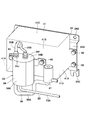
- FIG. 1 is a front view showing a hydraulic excavator according to a first embodiment of the present invention. It is a top view which shows an upper revolving body in the state which omitted a cab, a building cover, etc. It is a perspective view which expands from the diagonal upper side in the state which assembled the bracket, the cover, the urea water supply apparatus, the urea water filter, etc. It is a perspective view which expands and shows from diagonally lower side in the state which assembled the bracket, the cover, the urea water supply apparatus, the urea water filter. It is sectional drawing which shows typically the internal structure of a urea water filter. It is a circuit diagram which shows an exhaust-gas purification apparatus.
- FIG. 1 to FIG. 6 show a first embodiment of the present invention.
- a hydraulic excavator 1 includes a crawler-type lower traveling body 2 capable of self-running, and an upper revolving body 3 that is provided on the lower traveling body 2 so as to be capable of turning and constitutes a vehicle body together with the lower traveling body 2.
- the front revolving unit 3 is provided with a front device 4 that can be raised and lowered and that performs excavation work of earth and sand.
- the upper revolving unit 3 is provided on the rear side of the revolving frame 5 that forms the support structure, on the rear side of the revolving frame 5, and is provided on the left side of the front part of the revolving frame 5.
- the revolving frame 5 is erected on a bottom plate 5A made of a thick steel plate or the like extending in the front and rear directions, and on the bottom plate 5A, and forward and rear with a predetermined interval in the left and right directions.
- a bottom plate 5A made of a thick steel plate or the like extending in the front and rear directions, and on the bottom plate 5A, and forward and rear with a predetermined interval in the left and right directions.
- a purification device assembly 39 which will be described later, is attached to the rear surface side of the connecting plate 5G.
- the engine 9 is located in front of the counterweight 6 and is provided in a horizontally placed state on the turning frame 5 extending left and right.
- a cooling fan 9 ⁇ / b> A for supplying cooling air to a heat exchanger 11 described later is provided on the left side of the engine 9.
- a hydraulic pump 12 described later is provided on the right side of the engine 9.
- a water jacket 9 ⁇ / b> B through which cooling water for suppressing a temperature rise during operation is provided in the engine 9.
- a cooling water pump 9C for supplying cooling water is provided on the inflow side of the water jacket 9B.
- the water jacket 9B is connected to a heat exchanger 11 described later.
- the cooling water circulates between the water jacket 9B and the heat exchanger 11 by driving the cooling water pump 9C.
- a part of the cooling water (warm water) whose temperature has been increased by cooling the engine 9 is also supplied to the urea water filter 33 and the urea water supply device 25 through a cooling water supply passage 36 described later.
- an exhaust pipe 10 for discharging exhaust gas is connected to the engine 9 (see FIG. 2).
- the exhaust pipe 10 is formed as a metal pipe line extending leftward and rightward from the front position of the engine 9.
- the exhaust pipe 10 guides high-temperature exhaust gas discharged from the engine 9 to an exhaust gas aftertreatment device 16 which will be described later.
- the heat exchanger 11 is disposed on the left side of the engine 9.
- the heat exchanger 11 is provided so as to face the cooling fan 9 ⁇ / b> A of the engine 9.
- the heat exchanger 11 includes, for example, a radiator 11A that circulates in the water jacket 9B of the engine 9 and cools the heated coolant, an oil cooler that cools the working oil, and an intercooler that cools the air that the engine 9 sucks (all are Etc.).
- the hydraulic pump 12 is provided on the right side of the engine 9.
- the hydraulic pump 12 is driven by the engine 9.
- the hydraulic pump 12 uses hydraulic oil supplied from a hydraulic oil tank 13 described later as pressure oil to control various actuators provided in the lower traveling body 2, the front device 4, and the like (not shown). )
- the hydraulic oil tank 13 is located on the front side of the hydraulic pump 12 and is provided on the right side of the revolving frame 5.
- the hydraulic oil tank 13 stores hydraulic oil for driving each actuator.
- the fuel tank 14 is located on the front side of the hydraulic oil tank 13 and is provided in the turning frame 5.
- the exhaust gas purifying device 15 purifies the exhaust gas discharged from the engine 9 and is disposed on the upper side of the hydraulic pump 12, for example.
- the exhaust gas purification device 15 removes harmful substances in the exhaust gas discharged from the engine 9. Further, the exhaust gas purifying device 15 includes a silencer mechanism for reducing exhaust gas noise.
- the exhaust gas purification device 15 includes an exhaust gas aftertreatment device 16 having a urea selective reduction catalyst 19 and a urea water injection valve 21, which will be described later, a urea water tank 22, a urea water pipe 23, a urea water supply device 25, and a urea water filter. 33 is provided.
- the exhaust gas aftertreatment device 16 is connected to the outlet side of the exhaust pipe 10.
- the exhaust gas aftertreatment device 16 includes, for example, a cylindrical cylinder 17 extending in the front and rear directions, a first oxidation catalyst 18, a urea selective reduction catalyst 19, and a second oxidation catalyst provided in the cylinder 17. 20 and the urea water injection valve 21.
- the cylindrical body 17 is formed as a sealed container with both ends closed.
- An exhaust pipe 10 is connected to a front side portion that is upstream of the cylindrical body 17.
- the tubular body 17 is provided with a tail tube 17A located at a rear side portion on the downstream side.
- a first oxidation catalyst 18, a urea selective reduction catalyst 19, and a second oxidation catalyst 20 are arranged at intervals in the length direction.
- a urea water injection valve 21 is attached to the cylindrical body 17 so as to be positioned between the first oxidation catalyst 18 and the urea selective reduction catalyst 19.
- the first oxidation catalyst 18 is made of, for example, a ceramic cell-shaped cylinder, and has a large number of through holes formed in the axial direction thereof, and the inner surface is coated with a noble metal or the like.
- the first oxidation catalyst 18 oxidizes carbon monoxide (CO), hydrocarbon (HC), etc. contained in the exhaust gas by circulating the exhaust gas through each through hole at a predetermined temperature. Remove. Further, the particulate matter (PM) is also burned and removed as necessary.
- the urea selective reduction catalyst 19 is made of, for example, a ceramic cell-like cylinder, and has a large number of through holes formed in the axial direction thereof, and the inner surface is coated with a noble metal.
- the urea selective reduction catalyst 19 selectively reduces nitrogen oxide (NOx) contained in the exhaust gas discharged from the engine 9 with ammonia generated from the urea aqueous solution, and decomposes it into nitrogen and water.
- NOx nitrogen oxide
- the second oxidation catalyst 20 is made of a ceramic cell-like cylindrical body in substantially the same manner as the first oxidation catalyst 18 described above, and has a large number of through-holes formed in the axial direction and coated with a noble metal on the inner surface. ing. Thereby, the second oxidation catalyst 20 oxidizes residual ammonia remaining after reducing the nitrogen oxides by the urea selective reduction catalyst 19 and separates it into nitrogen and water.
- the urea water injection valve 21 is located between the first oxidation catalyst 18 and the urea selective reduction catalyst 19 and is attached to the cylindrical body 17.
- the urea water injection valve 21 injects a urea aqueous solution toward the exhaust gas flowing through the cylindrical body 17. That is, the urea water injection valve 21 is connected to a urea water tank 22 via a urea water pipe 23 described later, and the urea water as a reducing agent is located upstream of the urea selective reduction catalyst 19 and is located in the cylinder 17. To spray.
- the urea water tank 22 is provided on the revolving frame 5 as an example of an installation location, located in front of the fuel tank 14.
- the urea water tank 22 stores urea water as a reducing agent, and is connected to a urea water injection valve 21 via a urea water pipe 23 described later.
- the urea water in the urea water tank 22 is supplied to the urea water injection valve 21 through the urea water pipe 23 by driving a urea water supply device 25 described later.
- the urea water pipe line 23 connects between the urea water tank 22 and the urea water injection valve 21.
- the urea water pipe 23 is composed of, for example, a resin hose, a metal pipe, or both a resin hose and a metal pipe, and urea water stored in the urea water tank 22 is injected with urea water. It circulates toward the valve 21.
- a urea water supply device 25 and a urea water filter 33 which will be described later, are provided.
- the urea water conduit 23 is connected to the urea water tank 22 at one end on the upstream side when supplying urea water, and the other end on the downstream side is urea which will be described later.
- a tank side pipe line portion 23A connected to the lower part of the filter case 34 of the water filter 33, and a supply apparatus side pipe line part having one end connected to the upper part of the filter case 34 and the other end connected to the urea water supply device 25.
- the supply device side pipe line portion 23 ⁇ / b> B can be formed short by arranging the urea water supply device 25 and the urea water filter 33 close to each other as a part of the purification device assembly 39.
- the urea water filter 33 is arranged upstream of the urea water supply device 25 in the urea water supply direction.
- the urea water filter 33 performs an operation of returning the urea water remaining in the urea water pipe line 23, the urea water filter 33, and the like to the urea water tank 22. Therefore, air and urea water are mixed in the supply device side pipe line section 23 ⁇ / b> B and the urea water filter 33 between the urea water supply device 25 and the urea water tank 22.
- the urea water supply device 25 sucks up urea water from the urea water tank 22, but at that time, the urea water and air are sucked up simultaneously. If the urea water and the air are sucked up at the same time as described above, there is a possibility that a malfunction (for example, destabilization of the supply pressure of the urea water) may occur due to the engagement of the air with the urea water pump 27.
- urea water and air can be separated by devising a connection position between the tank side pipe section 23A and the supply apparatus side pipe section 23B as described later.
- the separation effect of urea water and air in the urea water filter 33 does not reach the supply device side pipe section 23B.
- the mixed state of the air and the urea water in the supply device side conduit portion 23B can be suppressed as much as possible by forming the supply device side conduit portion 23B short.
- the urea water pump 27 can prevent problems due to air entrapment.
- bracket 24 the urea water supply device 25, and the urea water filter 33, which are characteristic portions of the present embodiment, and the urea water supply device 25 and the urea water filter 33 are attached to the revolving frame 5 using the bracket 24.
- the structure will be described.
- the bracket 24 is attached to the rear surface of the connecting plate 5G of the revolving frame 5.
- the bracket 24 has a urea water supply device 25 attached to the connecting plate 5G.
- the bracket 24 includes a horizontally-long rectangular supply device mounting plate 24A, an upper mounting plate 24B bent in a crank shape on the upper side of the supply device mounting plate 24A, and a longitudinal direction of the lower side of the supply device mounting plate 24A.
- the lower mounting plate 24 ⁇ / b> C is provided by bending at both ends in a crank shape.
- a urea water supply device 25 and a cover 31 are attached to the supply device mounting plate 24 ⁇ / b> A of the bracket 24.
- the upper mounting plate 24B and each lower mounting plate 24C of the bracket 24 are mounted on the rear surface of the connecting plate 5G using bolts (not shown).
- the urea water supply device 25 is provided in the middle of the urea water conduit 23, that is, between the supply device side conduit portion 23B and the injection valve side conduit portion 23C.
- the urea water supply device 25 supplies urea water from the urea water tank 22 toward the urea water injection valve 21.
- the urea water supply device 25 is located downstream of the casing 26, the urea water pump 27 (see FIG. 6) built in the casing 26, and the urea water pump 27 when supplying the urea water to the casing 26.
- the built-in filter 28 and a pressure sensor 29 provided in the casing 26 are located downstream of the built-in filter 28.
- the casing 26 is detachably attached to the supply device mounting plate 24A of the bracket 24 using bolts (not shown).
- the casing 26 passes through a urea water pump 27 and a built-in filter 28, and a main passage 26 ⁇ / b> A that connects the supply device side pipe portion 23 ⁇ / b> B and the injection valve side pipe portion 23 ⁇ / b> C of the urea water pipe 23 and a built-in filter 28.
- a return passage 26B branched from the main passage 26A, which is located on the downstream side when supplying urea water.
- a heater passage 26 ⁇ / b> C is provided in the casing 26 so as to pass, for example, the vicinity of the urea water pump 27 and the built-in filter 28.
- a urea water inlet joint 26D serving as an inlet of the main passage 26A
- a urea water outlet joint 26E serving as an outlet of the main passage 26A
- a urea water return joint 26F serving as an outlet of the return passage 26B
- a cooling water inlet joint 26G serving as an inlet of the heater passage 26C
- a cooling water outlet joint 26H serving as an outlet of the heater passage 26C are provided.
- the other end of the supply device side pipe section 23B that forms the urea water pipe line 23 is connected to the urea water inlet joint 26D.
- One end of an injection valve side pipe line portion 23C is connected to the urea water outlet joint 26E.
- One end of a urea water return passage 30 for returning urea water to the urea water tank 22 is connected to the urea water return joint 26F.
- the other end of a second passage 36B of a cooling water supply passage 36 to be described later is connected to the cooling water inlet joint 26G.
- One end of a cooling water return passage 38 to be described later is connected to the cooling water outlet joint 26H.
- the casing 26 is provided with a filter mounting space 26J (see FIG. 4) for mounting the built-in filter 28.
- the filter mounting space 26J is formed to open downward. Thereby, the built-in filter 28 can be attached to the filter mounting space 26J from below, and can be removed downward.
- the urea water pump 27 is disposed upstream of the main passage 26A when supplying urea water.
- the urea water pump 27 is driven by, for example, an electric motor (not shown) to pump the urea water in the urea water tank 22 to the urea water injection valve 21 through the urea water conduit 23.
- the built-in filter 28 is located in the main passage 26A, located between the urea water pump 27 and the branch point of the return passage 26B.
- the built-in filter 28 can capture foreign matters mixed in the urea water supplied toward the urea water injection valve 21.
- the built-in filter 28 when the built-in filter 28 is attached to the casing 26, it can be attached from the lower side opened to the filter mounting space 26J.
- the cover 31 covering the urea water supply device 25 has the opening 31C that opens downward, the built-in filter 28 can be easily attached and detached through the opening 31C.
- the cover 31 is attached to the bracket 24 so as to cover the urea water supply device 25.
- the cover 31 is disposed at a position sandwiching the urea water supply device 25 from the lateral direction, and sandwiches the urea water supply device 25 with a pair of side plates 31A attached to the supply device mounting plate 24A of the bracket 24 using bolts 32.
- the filter mounting plate 31B is located on the opposite side of the bracket 24 and provided over the tip of each side plate 31A.
- the cover 31 covers the periphery of the urea water supply device 25, and the upper side and the lower side are opened.
- an opening 31 ⁇ / b> C for allowing the built-in filter 28 to pass when the built-in filter 28 is attached to and detached from the urea water supply device 25 is provided below the cover 31. ing. Accordingly, the built-in filter 28 can be easily attached and detached through the opening 31C.
- the urea water filter 33 is attached to the filter attachment plate 31B of the cover 31.
- the urea water filter 33 is provided between the urea water tank 22 and the urea water supply device 25 in the middle of the urea water pipe 23 and captures foreign matters mixed in the urea water.
- the exhaust gas purifying device 15 by providing the two filters, the built-in filter 28 and the urea water filter 33 described above, foreign matters mixed in the urea water can be reliably captured.
- the urea water filter 33 includes, for example, a filter case 34 formed of a cylindrical container, and a filter element 35 that is provided in the filter case 34 and captures foreign matters mixed in the urea water.
- the filter case 34 includes a circular cylindrical body 34A, an upper surface plate 34B, and a lower surface plate 34C.
- the filter case 34 is detachably attached to the filter attachment plate 31 ⁇ / b> B of the cover 31 using bolts 40. Thereby, the urea water filter 33 can be replaced by loosening the bolt 40.
- the lower surface plate 34C of the filter case 34 is provided with a urea water inlet joint 34E that opens to the lower portion of the urea water storage chamber 34D.
- the upper surface plate 34B of the filter case 34 is provided with a urea water outlet joint 34F that opens to an upper portion of the urea water storage chamber 34D.
- the other end of the tank side pipe section 23A constituting the urea water pipe line 23 is connected to the urea water inlet joint 34E.
- the other end of the tank side pipe portion 23 ⁇ / b> A opens to the lower part of the urea water storage chamber 34 ⁇ / b> D of the filter case 34.
- one end of a supply device side pipe line portion 23 ⁇ / b> B constituting the urea water pipe line 23 is connected to the urea water outlet joint 34 ⁇ / b> F.
- one end of supply device side pipe line part 23B is opened to the upper part of urea water storage room 34D.
- the filter case 34 is provided with a heater passage 34G so as to pass in the vicinity of the filter element 35, for example.
- a cooling water inlet joint 34 ⁇ / b> H is provided on the lower surface plate 34 ⁇ / b> C of the filter case 34.
- the upper surface plate 34B of the filter case 34 is provided with a cooling water outlet joint 34J.
- the other end of a first passage 36A of a cooling water supply passage 36 described later is connected to the cooling water inlet joint 34H, and one end of a second passage 36B is connected to the cooling water outlet joint 34J.
- the urea water filter 33 configured in this manner allows urea water from the urea water tank 22 to flow into the urea water storage chamber 34D from below the urea water storage chamber 34D.
- urea water flows into the urea water storage chamber 34D so as not to entrain the internal air, and most of the air in the urea water storage chamber 34D is directed to the supply device side pipe section 23B side. Spill.
- the urea water filter 33 can cause the urea water not mixed with air to flow out to the supply device side pipe section 23B side.
- the urea water that has flowed into the urea water storage chamber 34D passes through the filter element 35, so that foreign matters are removed and cleaned. Thereby, the urea water filter 33 can flow out clean urea water to the supply apparatus side pipe line part 23B side.
- the cooling water supply passage 36 is provided across the outlet side of the water jacket 9 ⁇ / b> B of the engine 9, the urea water supply device 25, and the urea water filter 33.
- the cooling water supply passage 36 is provided in the first passage 36A that connects the outlet side of the water jacket 9B and the cooling water inlet joint 34H of the filter case 34, the cooling water outlet joint 34J, and the casing 26 of the urea water supply device 25.
- the second passage 36B is connected to the cooling water inlet joint 26G.
- the cooling water control valve 37 is attached to the cover 31 in the middle of the first passage 36 ⁇ / b> A of the cooling water supply passage 36.
- the cooling water control valve 37 is opened when the urea water in the urea water supply device 25 and the urea water filter 33 is frozen or freezing. Thereby, the cooling water control valve 37 supplies the cooling water heated by cooling the engine 9 to the urea water supply device 25 and the urea water filter 33.
- the cooling water return passage 38 can return the cooling water that has warmed the urea water supply device 25 and the urea water filter 33 to the water jacket 9B.
- the cooling water return passage 38 connects the cooling water outlet joint 26H of the casing 26 and the inlet side of the water jacket 9B.
- the purification device assembly 39 is configured by assembling the bracket 24, the urea water supply device 25, the cover 31, the urea water filter 33, and the cooling water control valve 37 described above. Yes. Since this purification device assembly 39 can be assembled at a place different from the main assembly line, the workability at the time of assembly can be improved.
- the hydraulic excavator 1 has the above-described configuration, and the operation thereof will be described next.
- the operator gets on the cab 7 and operates the engine 9.
- the operator can run the hydraulic excavator 1 by operating a travel operation lever / pedal (not shown) disposed in the cab 7.
- the operator can perform excavation work of earth and sand using the front device 4 by operating an operation lever (not shown) for work.
- the exhaust gas discharged from the engine 9 passes through the exhaust pipe 10 and the exhaust gas aftertreatment device 16 and is discharged into the atmosphere.
- carbon monoxide (CO), hydrocarbon (HC), etc. contained in the exhaust gas are oxidized and removed by the first oxidation catalyst 18 provided in the exhaust gas aftertreatment device 16. Further, particulate matter (PM) is burned and removed as necessary.
- urea water is injected toward the exhaust gas from the urea water injection valve 21, and the nitrogen oxide is decomposed into nitrogen and water by the urea selective reduction catalyst 19.
- the second oxidation catalyst 20 oxidizes residual ammonia and separates it into nitrogen and water, so that exhaust gas that has been sufficiently purified can be discharged into the atmosphere.
- the urea water pump 27 of the urea water supply device 25 is driven to suck up the urea water in the urea water tank 22 through the urea water pipe 23.
- the urea water flowing through the tank side pipe part 23A of the urea water pipe line 23 passes through the urea water filter 33, so that the foreign matter is removed and cleaned by the filter element 35 to the supply apparatus side pipe part 23B. leak.
- the urea water from the tank side pipe section 23A flows from the lower part of the urea water storage chamber 34D.
- urea water can be made to flow into urea water storage chamber 34D so that internal air may not be caught, and urea water and air can be separated into two layers of upper and lower directions.
- the urea water that has flowed into the urea water storage chamber 34D passes through the filter element 35 and is purified, and then flows out to the supply device side pipe section 23B.
- the supply device side conduit portion 23B of the urea water conduit 23 is formed short by arranging the urea water supply device 25 and the urea water filter 33 close as a part of the purification device assembly 39. Thereby, the mixed state of the air and urea water in the supply apparatus side pipe line part 23B can be suppressed as much as possible.
- the urea water supplied to the urea water supply device 25 through the supply device side pipe section 23B flows into the main passage 26A and is pumped from the urea water pump 27.
- the urea water that has flowed into the main passage 26A is suppressed from being mixed with air, the urea water can be stably supplied without causing a problem due to air biting.
- the urea water pumped from the urea water pump 27 passes through the built-in filter 28, so that foreign matters are removed and further purified.
- the purified urea water is supplied to the urea water injection valve 21 through the injection valve side pipe section 23C.
- the urea water that has not been supplied to the urea water injection valve 21 is returned to the urea water tank 22 through the return passage 26 ⁇ / b> B and the urea water return passage 30.
- the urea water supply device 25 is provided in the middle of the urea water pipe 23 and supplies urea water from the urea water tank 22 toward the urea water injection valve 21.
- a bracket 24 for attaching the urea water supply device 25 is attached to the turning frame 5 of the upper turning body 3.
- a cover 31 that covers the urea water supply device 25 is attached to the bracket 24.
- the urea water filter 33 that is provided in the middle of the urea water pipe 23 and captures foreign matters mixed in the urea water is configured to be attached to the cover 31.
- the bracket 24, the urea water supply device 25, the cover 31, the urea water filter 33, and the like can be formed as one purification device assembly 39.
- the urea water supply device 25 and the urea water filter 33 can be attached to the revolving frame 5 as the purification device assembly 39.
- the urea water supply device 25 and the urea water filter 33 can be easily attached to the revolving frame 5 and the maintainability of the urea water filter 33 can be improved.
- the urea water filter 33 includes a filter case 34 having a urea water storage chamber 34D that stores urea water therein, and a filter element 35 that is provided in the urea water storage chamber 34D of the filter case 34 and captures foreign matters mixed in the urea water. And.
- the urea water pipe 23 has one end connected to the urea water tank 22 and the other end connected to the lower part of the filter case 34, a tank side pipe part 23A, one end connected to the upper part of the filter case 34, and the other end And a supply device side pipe section 23 ⁇ / b> B connected to the urea water supply device 25.
- the urea water from the urea water tank 22 can flow into the urea water storage chamber 34D from the lower part of the urea water storage chamber 34D. That is, since urea water flows into the urea water storage chamber 34D from below so as not to entrain the internal air, the air in the urea water storage chamber 34D is pushed up by the inflowing urea water and supplied to the supply device side pipe. It flows out to the road part 23B side. Thereby, the urea water filter 33 can supply the urea water in which the air is not mixed to the supply device side pipe section 23B side after the air has flowed out.
- the urea water supply device 25 is detachably provided with a built-in filter 28 that captures foreign matters mixed in the urea water.
- a built-in filter 28 that captures foreign matters mixed in the urea water.
- an opening 31 ⁇ / b> C for allowing the built-in filter 28 to pass when the built-in filter 28 is attached to and detached from the urea water supply device 25 is provided below the cover 31, an opening 31 ⁇ / b> C for allowing the built-in filter 28 to pass when the built-in filter 28 is attached to and detached from the urea water supply device 25 is provided. Accordingly, the built-in filter 28 can be easily attached and detached through the opening 31C.
- FIG. 7 shows a second embodiment of the present invention.
- a feature of the present embodiment is that the cover is configured to open only to the lower side where the opening is provided in a state of being attached to the bracket.
- the same components as those in the first embodiment described above are denoted by the same reference numerals, and the description thereof is omitted.
- the cover 41 is attached to the bracket 24 so as to cover the urea water supply device 25.
- the cover 41 is disposed at a position sandwiching the urea water supply device 25 from the lateral direction, and sandwiches the urea water supply device 25 with a pair of side plates 41A attached to the supply device mounting plate 24A of the bracket 24 using bolts 32.
- the filter mounting plate 41B provided over the tip of each side plate 41A, and the upper side of each side plate 41A and the filter mounting plate 41B so as to cover the upper side of the urea water supply device 25.
- an upper surface plate 41 ⁇ / b> C whereby, the cover 41 is attached to the bracket 24, and only the lower side where the opening 41D is provided is open.
- the cover 41 covers the upper side of the urea water supply device 25 by the upper surface plate 41C, the urea water supply device 25 and the hose connected to the urea water supply device 25 are covered. Can be protected.
- FIG. 8 shows a third embodiment of the present invention.
- the feature of this embodiment is that the cover is configured to open sideways and downward.
- the same components as those in the first embodiment described above are denoted by the same reference numerals, and the description thereof is omitted.
- the cover 51 is attached to the bracket 24 so as to cover the urea water supply device 25.
- the cover 51 is located on the opposite side of the bracket 24 with the side plate 51A facing one side in the lateral direction of the urea water supply device 25 and the urea water supply device 25 interposed therebetween, and a filter attached to the tip of the side plate 51A.
- the plate 51B is constituted by a side plate 51A and an upper plate 51C provided on the upper part of the filter mounting plate 51B so as to cover the upper side of the urea water supply device 25. Thereby, the cover 51 is attached to the bracket 24, and the other side in the lateral direction and the lower side where the opening 51D is provided are opened.
- the present invention is not limited to this, and for example, a particulate matter removal filter (DPF) may be provided in the cylinder of the exhaust gas aftertreatment device and located downstream of the first oxidation catalyst.
- This particulate matter removal filter purifies exhaust gas by collecting particulate matter (PM) in exhaust gas discharged from the engine, and burning and removing it.
- the hydraulic excavator 1 including the crawler type lower traveling body 2 is described as an example of the construction machine.
- the present invention is not limited to this, and may be applied to, for example, a hydraulic excavator provided with a wheel-type lower traveling body. Besides, it can be widely applied to other construction machines such as hydraulic cranes.
Priority Applications (4)
| Application Number | Priority Date | Filing Date | Title |
|---|---|---|---|
| KR1020207005672A KR102293769B1 (ko) | 2018-03-19 | 2019-01-31 | 건설기계 |
| CN201980004197.7A CN111051110B (zh) | 2018-03-19 | 2019-01-31 | 工程机械 |
| US16/642,468 US11085352B2 (en) | 2018-03-19 | 2019-01-31 | Construction machine |
| EP19772199.6A EP3653423B1 (de) | 2018-03-19 | 2019-01-31 | Baumaschine |
Applications Claiming Priority (2)
| Application Number | Priority Date | Filing Date | Title |
|---|---|---|---|
| JP2018051291A JP6934439B2 (ja) | 2018-03-19 | 2018-03-19 | 建設機械 |
| JP2018-051291 | 2018-03-19 |
Publications (1)
| Publication Number | Publication Date |
|---|---|
| WO2019181226A1 true WO2019181226A1 (ja) | 2019-09-26 |
Family
ID=67986092
Family Applications (1)
| Application Number | Title | Priority Date | Filing Date |
|---|---|---|---|
| PCT/JP2019/003386 WO2019181226A1 (ja) | 2018-03-19 | 2019-01-31 | 建設機械 |
Country Status (6)
| Country | Link |
|---|---|
| US (1) | US11085352B2 (de) |
| EP (1) | EP3653423B1 (de) |
| JP (1) | JP6934439B2 (de) |
| KR (1) | KR102293769B1 (de) |
| CN (1) | CN111051110B (de) |
| WO (1) | WO2019181226A1 (de) |
Families Citing this family (3)
| Publication number | Priority date | Publication date | Assignee | Title |
|---|---|---|---|---|
| JP7235973B2 (ja) * | 2019-09-06 | 2023-03-09 | サミー株式会社 | ぱちんこ遊技機 |
| KR102204806B1 (ko) * | 2020-07-02 | 2021-01-19 | 현대머티리얼 주식회사 | 배기가스 처리장치용 우레아 도징유닛 |
| DE102020214869A1 (de) * | 2020-11-26 | 2022-06-02 | Vitesco Technologies GmbH | Fördervorrichtung mit Filterelement |
Citations (6)
| Publication number | Priority date | Publication date | Assignee | Title |
|---|---|---|---|---|
| DE10139139A1 (de) * | 2001-08-09 | 2003-06-12 | Bosch Gmbh Robert | Dosiersystem zur Dosierung eines Reduktionsmittels für eine Abgasnachbehandlung |
| WO2007126366A1 (en) | 2006-04-27 | 2007-11-08 | Volvo Lastvagnar Ab | A liquid receptacle for a vehicle |
| US20130000281A1 (en) * | 2011-06-30 | 2013-01-03 | Caterpillar Inc. | Def pump mounted to tank |
| CN104948365A (zh) * | 2015-07-04 | 2015-09-30 | 安徽洪福新型汽车科技有限公司 | 一种直列式可变预行程燃油泵及其精确控制的scr系统 |
| JP2016094803A (ja) * | 2014-11-17 | 2016-05-26 | コベルコ建機株式会社 | 建設機械 |
| JP2017133289A (ja) * | 2016-01-29 | 2017-08-03 | 日立建機株式会社 | 建設機械 |
Family Cites Families (9)
| Publication number | Priority date | Publication date | Assignee | Title |
|---|---|---|---|---|
| JP2009138551A (ja) * | 2007-12-04 | 2009-06-25 | Tokyo Radiator Mfg Co Ltd | 尿素水タンク |
| JP5101324B2 (ja) * | 2008-02-07 | 2012-12-19 | 日立建機株式会社 | 建設機械のNOx低減装置の配設構造 |
| JP2010007617A (ja) * | 2008-06-30 | 2010-01-14 | Denso Corp | 還元剤供給システム |
| DE102011010640A1 (de) * | 2011-02-09 | 2012-08-09 | Emitec France S.A.S | Fördereinheit zur Förderung von Reduktionsmittel |
| CN110219335B (zh) * | 2013-10-08 | 2022-01-11 | 住友建机株式会社 | 挖土机 |
| JP6088458B2 (ja) * | 2014-03-17 | 2017-03-01 | 日立建機株式会社 | 建設機械の尿素水供給システム |
| JP6560587B2 (ja) * | 2015-10-06 | 2019-08-14 | 日立建機株式会社 | 建設機械 |
| GB2546111A (en) * | 2016-01-11 | 2017-07-12 | Micro-Mesh Eng Ltd | Vehicle fluid delivery system |
| CN206592183U (zh) * | 2017-02-27 | 2017-10-27 | 华晨汽车集团控股有限公司 | 轻客scr系统尿素供给单元 |
-
2018
- 2018-03-19 JP JP2018051291A patent/JP6934439B2/ja active Active
-
2019
- 2019-01-31 US US16/642,468 patent/US11085352B2/en active Active
- 2019-01-31 WO PCT/JP2019/003386 patent/WO2019181226A1/ja unknown
- 2019-01-31 EP EP19772199.6A patent/EP3653423B1/de active Active
- 2019-01-31 CN CN201980004197.7A patent/CN111051110B/zh active Active
- 2019-01-31 KR KR1020207005672A patent/KR102293769B1/ko active IP Right Grant
Patent Citations (6)
| Publication number | Priority date | Publication date | Assignee | Title |
|---|---|---|---|---|
| DE10139139A1 (de) * | 2001-08-09 | 2003-06-12 | Bosch Gmbh Robert | Dosiersystem zur Dosierung eines Reduktionsmittels für eine Abgasnachbehandlung |
| WO2007126366A1 (en) | 2006-04-27 | 2007-11-08 | Volvo Lastvagnar Ab | A liquid receptacle for a vehicle |
| US20130000281A1 (en) * | 2011-06-30 | 2013-01-03 | Caterpillar Inc. | Def pump mounted to tank |
| JP2016094803A (ja) * | 2014-11-17 | 2016-05-26 | コベルコ建機株式会社 | 建設機械 |
| CN104948365A (zh) * | 2015-07-04 | 2015-09-30 | 安徽洪福新型汽车科技有限公司 | 一种直列式可变预行程燃油泵及其精确控制的scr系统 |
| JP2017133289A (ja) * | 2016-01-29 | 2017-08-03 | 日立建機株式会社 | 建設機械 |
Non-Patent Citations (1)
| Title |
|---|
| See also references of EP3653423A4 |
Also Published As
| Publication number | Publication date |
|---|---|
| KR102293769B1 (ko) | 2021-08-26 |
| EP3653423A4 (de) | 2021-01-13 |
| KR20200035988A (ko) | 2020-04-06 |
| JP6934439B2 (ja) | 2021-09-15 |
| CN111051110A (zh) | 2020-04-21 |
| CN111051110B (zh) | 2023-04-07 |
| EP3653423B1 (de) | 2022-11-16 |
| US20200256232A1 (en) | 2020-08-13 |
| EP3653423A1 (de) | 2020-05-20 |
| US11085352B2 (en) | 2021-08-10 |
| JP2019162925A (ja) | 2019-09-26 |
Similar Documents
| Publication | Publication Date | Title |
|---|---|---|
| CN107923142B (zh) | 工程机械 | |
| WO2019181226A1 (ja) | 建設機械 | |
| JP6212826B2 (ja) | 建設機械 | |
| JP2012219624A (ja) | 建設機械 | |
| WO2014084316A1 (ja) | エンジン装置 | |
| KR101834979B1 (ko) | 건설 기계 | |
| US10001041B2 (en) | Engine device | |
| KR20160133407A (ko) | 엔진 장치 | |
| JP6051079B2 (ja) | エンジン装置 | |
| JP2016217188A (ja) | エンジン装置 | |
| JP2017025743A (ja) | エンジン装置 | |
| JP6124631B2 (ja) | エンジン装置 | |
| KR20150074191A (ko) | 작업 차량 | |
| WO2019181151A1 (ja) | 排気ガス浄化装置 | |
| JP6124693B2 (ja) | エンジン装置 | |
| JP7271745B2 (ja) | 建設機械 | |
| JP2020019402A (ja) | 建設機械 | |
| JP6550354B2 (ja) | 建設機械 | |
| JP6046678B2 (ja) | 作業車両 | |
| JP7025307B2 (ja) | 建設機械 | |
| JP2022065361A (ja) | 建設機械 | |
| JP2022152621A (ja) | 建設機械 | |
| JP2019163712A (ja) | 排気ガス浄化装置 | |
| JP6233963B2 (ja) | エンジン装置 |
Legal Events
| Date | Code | Title | Description |
|---|---|---|---|
| 121 | Ep: the epo has been informed by wipo that ep was designated in this application |
Ref document number: 19772199 Country of ref document: EP Kind code of ref document: A1 |
|
| ENP | Entry into the national phase |
Ref document number: 2019772199 Country of ref document: EP Effective date: 20200211 |
|
| ENP | Entry into the national phase |
Ref document number: 20207005672 Country of ref document: KR Kind code of ref document: A |
|
| NENP | Non-entry into the national phase |
Ref country code: DE |