WO2019181226A1 - Construction machinery - Google Patents
Construction machinery Download PDFInfo
- Publication number
- WO2019181226A1 WO2019181226A1 PCT/JP2019/003386 JP2019003386W WO2019181226A1 WO 2019181226 A1 WO2019181226 A1 WO 2019181226A1 JP 2019003386 W JP2019003386 W JP 2019003386W WO 2019181226 A1 WO2019181226 A1 WO 2019181226A1
- Authority
- WO
- WIPO (PCT)
- Prior art keywords
- urea water
- filter
- supply device
- urea
- water supply
- Prior art date
Links
- 238000010276 construction Methods 0.000 title claims description 12
- WTHDKMILWLGDKL-UHFFFAOYSA-N urea;hydrate Chemical compound O.NC(N)=O WTHDKMILWLGDKL-UHFFFAOYSA-N 0.000 claims abstract description 362
- 238000002347 injection Methods 0.000 claims abstract description 38
- 239000007924 injection Substances 0.000 claims abstract description 38
- 239000007789 gas Substances 0.000 claims description 46
- 239000003054 catalyst Substances 0.000 claims description 35
- XSQUKJJJFZCRTK-UHFFFAOYSA-N Urea Chemical compound NC(N)=O XSQUKJJJFZCRTK-UHFFFAOYSA-N 0.000 claims description 21
- 239000004202 carbamide Substances 0.000 claims description 21
- MWUXSHHQAYIFBG-UHFFFAOYSA-N nitrogen oxide Inorganic materials O=[N] MWUXSHHQAYIFBG-UHFFFAOYSA-N 0.000 claims description 21
- 238000000746 purification Methods 0.000 claims description 19
- 238000011144 upstream manufacturing Methods 0.000 claims description 8
- 239000003638 chemical reducing agent Substances 0.000 claims description 5
- 239000000463 material Substances 0.000 abstract 1
- 239000000498 cooling water Substances 0.000 description 33
- 230000003647 oxidation Effects 0.000 description 17
- 238000007254 oxidation reaction Methods 0.000 description 17
- XLYOFNOQVPJJNP-UHFFFAOYSA-N water Substances O XLYOFNOQVPJJNP-UHFFFAOYSA-N 0.000 description 15
- IJGRMHOSHXDMSA-UHFFFAOYSA-N Atomic nitrogen Chemical compound N#N IJGRMHOSHXDMSA-UHFFFAOYSA-N 0.000 description 8
- 239000013618 particulate matter Substances 0.000 description 8
- QGZKDVFQNNGYKY-UHFFFAOYSA-N Ammonia Chemical compound N QGZKDVFQNNGYKY-UHFFFAOYSA-N 0.000 description 6
- 239000010720 hydraulic oil Substances 0.000 description 6
- 238000001816 cooling Methods 0.000 description 5
- 239000004215 Carbon black (E152) Substances 0.000 description 4
- UGFAIRIUMAVXCW-UHFFFAOYSA-N Carbon monoxide Chemical compound [O+]#[C-] UGFAIRIUMAVXCW-UHFFFAOYSA-N 0.000 description 4
- 229910002091 carbon monoxide Inorganic materials 0.000 description 4
- 229930195733 hydrocarbon Natural products 0.000 description 4
- 150000002430 hydrocarbons Chemical class 0.000 description 4
- 229910052757 nitrogen Inorganic materials 0.000 description 4
- 229910021529 ammonia Inorganic materials 0.000 description 3
- 239000000919 ceramic Substances 0.000 description 3
- 230000000694 effects Effects 0.000 description 3
- 229910052751 metal Inorganic materials 0.000 description 3
- 239000002184 metal Substances 0.000 description 3
- 229910000510 noble metal Inorganic materials 0.000 description 3
- 239000003921 oil Substances 0.000 description 3
- 239000007864 aqueous solution Substances 0.000 description 2
- 238000009412 basement excavation Methods 0.000 description 2
- 239000002828 fuel tank Substances 0.000 description 2
- 239000011347 resin Substances 0.000 description 2
- 229920005989 resin Polymers 0.000 description 2
- 239000004576 sand Substances 0.000 description 2
- 229910000831 Steel Inorganic materials 0.000 description 1
- 238000005452 bending Methods 0.000 description 1
- 238000004140 cleaning Methods 0.000 description 1
- 239000002826 coolant Substances 0.000 description 1
- 230000001687 destabilization Effects 0.000 description 1
- 238000010586 diagram Methods 0.000 description 1
- 238000007599 discharging Methods 0.000 description 1
- 238000007710 freezing Methods 0.000 description 1
- 230000008014 freezing Effects 0.000 description 1
- 238000007689 inspection Methods 0.000 description 1
- 238000009434 installation Methods 0.000 description 1
- 238000012423 maintenance Methods 0.000 description 1
- 230000007257 malfunction Effects 0.000 description 1
- 238000000926 separation method Methods 0.000 description 1
- 230000003584 silencer Effects 0.000 description 1
- 239000007921 spray Substances 0.000 description 1
- 239000010959 steel Substances 0.000 description 1
- 239000000126 substance Substances 0.000 description 1
Images


Classifications
-
- F—MECHANICAL ENGINEERING; LIGHTING; HEATING; WEAPONS; BLASTING
- F01—MACHINES OR ENGINES IN GENERAL; ENGINE PLANTS IN GENERAL; STEAM ENGINES
- F01N—GAS-FLOW SILENCERS OR EXHAUST APPARATUS FOR MACHINES OR ENGINES IN GENERAL; GAS-FLOW SILENCERS OR EXHAUST APPARATUS FOR INTERNAL COMBUSTION ENGINES
- F01N3/00—Exhaust or silencing apparatus having means for purifying, rendering innocuous, or otherwise treating exhaust
- F01N3/08—Exhaust or silencing apparatus having means for purifying, rendering innocuous, or otherwise treating exhaust for rendering innocuous
- F01N3/10—Exhaust or silencing apparatus having means for purifying, rendering innocuous, or otherwise treating exhaust for rendering innocuous by thermal or catalytic conversion of noxious components of exhaust
- F01N3/18—Exhaust or silencing apparatus having means for purifying, rendering innocuous, or otherwise treating exhaust for rendering innocuous by thermal or catalytic conversion of noxious components of exhaust characterised by methods of operation; Control
- F01N3/20—Exhaust or silencing apparatus having means for purifying, rendering innocuous, or otherwise treating exhaust for rendering innocuous by thermal or catalytic conversion of noxious components of exhaust characterised by methods of operation; Control specially adapted for catalytic conversion ; Methods of operation or control of catalytic converters
- F01N3/2066—Selective catalytic reduction [SCR]
-
- F—MECHANICAL ENGINEERING; LIGHTING; HEATING; WEAPONS; BLASTING
- F01—MACHINES OR ENGINES IN GENERAL; ENGINE PLANTS IN GENERAL; STEAM ENGINES
- F01N—GAS-FLOW SILENCERS OR EXHAUST APPARATUS FOR MACHINES OR ENGINES IN GENERAL; GAS-FLOW SILENCERS OR EXHAUST APPARATUS FOR INTERNAL COMBUSTION ENGINES
- F01N13/00—Exhaust or silencing apparatus characterised by constructional features ; Exhaust or silencing apparatus, or parts thereof, having pertinent characteristics not provided for in, or of interest apart from, groups F01N1/00 - F01N5/00, F01N9/00, F01N11/00
- F01N13/18—Construction facilitating manufacture, assembly, or disassembly
-
- B—PERFORMING OPERATIONS; TRANSPORTING
- B60—VEHICLES IN GENERAL
- B60K—ARRANGEMENT OR MOUNTING OF PROPULSION UNITS OR OF TRANSMISSIONS IN VEHICLES; ARRANGEMENT OR MOUNTING OF PLURAL DIVERSE PRIME-MOVERS IN VEHICLES; AUXILIARY DRIVES FOR VEHICLES; INSTRUMENTATION OR DASHBOARDS FOR VEHICLES; ARRANGEMENTS IN CONNECTION WITH COOLING, AIR INTAKE, GAS EXHAUST OR FUEL SUPPLY OF PROPULSION UNITS IN VEHICLES
- B60K13/00—Arrangement in connection with combustion air intake or gas exhaust of propulsion units
- B60K13/04—Arrangement in connection with combustion air intake or gas exhaust of propulsion units concerning exhaust
-
- E—FIXED CONSTRUCTIONS
- E02—HYDRAULIC ENGINEERING; FOUNDATIONS; SOIL SHIFTING
- E02F—DREDGING; SOIL-SHIFTING
- E02F9/00—Component parts of dredgers or soil-shifting machines, not restricted to one of the kinds covered by groups E02F3/00 - E02F7/00
- E02F9/08—Superstructures; Supports for superstructures
- E02F9/0858—Arrangement of component parts installed on superstructures not otherwise provided for, e.g. electric components, fenders, air-conditioning units
- E02F9/0866—Engine compartment, e.g. heat exchangers, exhaust filters, cooling devices, silencers, mufflers, position of hydraulic pumps in the engine compartment
-
- E—FIXED CONSTRUCTIONS
- E02—HYDRAULIC ENGINEERING; FOUNDATIONS; SOIL SHIFTING
- E02F—DREDGING; SOIL-SHIFTING
- E02F9/00—Component parts of dredgers or soil-shifting machines, not restricted to one of the kinds covered by groups E02F3/00 - E02F7/00
- E02F9/08—Superstructures; Supports for superstructures
- E02F9/0858—Arrangement of component parts installed on superstructures not otherwise provided for, e.g. electric components, fenders, air-conditioning units
- E02F9/0883—Tanks, e.g. oil tank, urea tank, fuel tank
-
- F—MECHANICAL ENGINEERING; LIGHTING; HEATING; WEAPONS; BLASTING
- F01—MACHINES OR ENGINES IN GENERAL; ENGINE PLANTS IN GENERAL; STEAM ENGINES
- F01N—GAS-FLOW SILENCERS OR EXHAUST APPARATUS FOR MACHINES OR ENGINES IN GENERAL; GAS-FLOW SILENCERS OR EXHAUST APPARATUS FOR INTERNAL COMBUSTION ENGINES
- F01N13/00—Exhaust or silencing apparatus characterised by constructional features ; Exhaust or silencing apparatus, or parts thereof, having pertinent characteristics not provided for in, or of interest apart from, groups F01N1/00 - F01N5/00, F01N9/00, F01N11/00
- F01N13/18—Construction facilitating manufacture, assembly, or disassembly
- F01N13/1805—Fixing exhaust manifolds, exhaust pipes or pipe sections to each other, to engine or to vehicle body
-
- F—MECHANICAL ENGINEERING; LIGHTING; HEATING; WEAPONS; BLASTING
- F01—MACHINES OR ENGINES IN GENERAL; ENGINE PLANTS IN GENERAL; STEAM ENGINES
- F01N—GAS-FLOW SILENCERS OR EXHAUST APPARATUS FOR MACHINES OR ENGINES IN GENERAL; GAS-FLOW SILENCERS OR EXHAUST APPARATUS FOR INTERNAL COMBUSTION ENGINES
- F01N13/00—Exhaust or silencing apparatus characterised by constructional features ; Exhaust or silencing apparatus, or parts thereof, having pertinent characteristics not provided for in, or of interest apart from, groups F01N1/00 - F01N5/00, F01N9/00, F01N11/00
- F01N13/18—Construction facilitating manufacture, assembly, or disassembly
- F01N13/1838—Construction facilitating manufacture, assembly, or disassembly characterised by the type of connection between parts of exhaust or silencing apparatus, e.g. between housing and tubes, between tubes and baffles
- F01N13/1844—Mechanical joints
- F01N13/1855—Mechanical joints the connection being realised by using bolts, screws, rivets or the like
-
- F—MECHANICAL ENGINEERING; LIGHTING; HEATING; WEAPONS; BLASTING
- F01—MACHINES OR ENGINES IN GENERAL; ENGINE PLANTS IN GENERAL; STEAM ENGINES
- F01N—GAS-FLOW SILENCERS OR EXHAUST APPARATUS FOR MACHINES OR ENGINES IN GENERAL; GAS-FLOW SILENCERS OR EXHAUST APPARATUS FOR INTERNAL COMBUSTION ENGINES
- F01N2570/00—Exhaust treating apparatus eliminating, absorbing or adsorbing specific elements or compounds
- F01N2570/14—Nitrogen oxides
-
- F—MECHANICAL ENGINEERING; LIGHTING; HEATING; WEAPONS; BLASTING
- F01—MACHINES OR ENGINES IN GENERAL; ENGINE PLANTS IN GENERAL; STEAM ENGINES
- F01N—GAS-FLOW SILENCERS OR EXHAUST APPARATUS FOR MACHINES OR ENGINES IN GENERAL; GAS-FLOW SILENCERS OR EXHAUST APPARATUS FOR INTERNAL COMBUSTION ENGINES
- F01N2590/00—Exhaust or silencing apparatus adapted to particular use, e.g. for military applications, airplanes, submarines
- F01N2590/08—Exhaust or silencing apparatus adapted to particular use, e.g. for military applications, airplanes, submarines for heavy duty applications, e.g. trucks, buses, tractors, locomotives
-
- F—MECHANICAL ENGINEERING; LIGHTING; HEATING; WEAPONS; BLASTING
- F01—MACHINES OR ENGINES IN GENERAL; ENGINE PLANTS IN GENERAL; STEAM ENGINES
- F01N—GAS-FLOW SILENCERS OR EXHAUST APPARATUS FOR MACHINES OR ENGINES IN GENERAL; GAS-FLOW SILENCERS OR EXHAUST APPARATUS FOR INTERNAL COMBUSTION ENGINES
- F01N2610/00—Adding substances to exhaust gases
- F01N2610/02—Adding substances to exhaust gases the substance being ammonia or urea
-
- F—MECHANICAL ENGINEERING; LIGHTING; HEATING; WEAPONS; BLASTING
- F01—MACHINES OR ENGINES IN GENERAL; ENGINE PLANTS IN GENERAL; STEAM ENGINES
- F01N—GAS-FLOW SILENCERS OR EXHAUST APPARATUS FOR MACHINES OR ENGINES IN GENERAL; GAS-FLOW SILENCERS OR EXHAUST APPARATUS FOR INTERNAL COMBUSTION ENGINES
- F01N2610/00—Adding substances to exhaust gases
- F01N2610/14—Arrangements for the supply of substances, e.g. conduits
- F01N2610/1406—Storage means for substances, e.g. tanks or reservoirs
-
- F—MECHANICAL ENGINEERING; LIGHTING; HEATING; WEAPONS; BLASTING
- F01—MACHINES OR ENGINES IN GENERAL; ENGINE PLANTS IN GENERAL; STEAM ENGINES
- F01N—GAS-FLOW SILENCERS OR EXHAUST APPARATUS FOR MACHINES OR ENGINES IN GENERAL; GAS-FLOW SILENCERS OR EXHAUST APPARATUS FOR INTERNAL COMBUSTION ENGINES
- F01N2610/00—Adding substances to exhaust gases
- F01N2610/14—Arrangements for the supply of substances, e.g. conduits
- F01N2610/1426—Filtration means
-
- F—MECHANICAL ENGINEERING; LIGHTING; HEATING; WEAPONS; BLASTING
- F01—MACHINES OR ENGINES IN GENERAL; ENGINE PLANTS IN GENERAL; STEAM ENGINES
- F01N—GAS-FLOW SILENCERS OR EXHAUST APPARATUS FOR MACHINES OR ENGINES IN GENERAL; GAS-FLOW SILENCERS OR EXHAUST APPARATUS FOR INTERNAL COMBUSTION ENGINES
- F01N2610/00—Adding substances to exhaust gases
- F01N2610/14—Arrangements for the supply of substances, e.g. conduits
- F01N2610/1433—Pumps
-
- F—MECHANICAL ENGINEERING; LIGHTING; HEATING; WEAPONS; BLASTING
- F01—MACHINES OR ENGINES IN GENERAL; ENGINE PLANTS IN GENERAL; STEAM ENGINES
- F01N—GAS-FLOW SILENCERS OR EXHAUST APPARATUS FOR MACHINES OR ENGINES IN GENERAL; GAS-FLOW SILENCERS OR EXHAUST APPARATUS FOR INTERNAL COMBUSTION ENGINES
- F01N2610/00—Adding substances to exhaust gases
- F01N2610/14—Arrangements for the supply of substances, e.g. conduits
- F01N2610/1453—Sprayers or atomisers; Arrangement thereof in the exhaust apparatus
- F01N2610/146—Control thereof, e.g. control of injectors or injection valves
-
- F—MECHANICAL ENGINEERING; LIGHTING; HEATING; WEAPONS; BLASTING
- F01—MACHINES OR ENGINES IN GENERAL; ENGINE PLANTS IN GENERAL; STEAM ENGINES
- F01N—GAS-FLOW SILENCERS OR EXHAUST APPARATUS FOR MACHINES OR ENGINES IN GENERAL; GAS-FLOW SILENCERS OR EXHAUST APPARATUS FOR INTERNAL COMBUSTION ENGINES
- F01N3/00—Exhaust or silencing apparatus having means for purifying, rendering innocuous, or otherwise treating exhaust
- F01N3/08—Exhaust or silencing apparatus having means for purifying, rendering innocuous, or otherwise treating exhaust for rendering innocuous
- F01N3/10—Exhaust or silencing apparatus having means for purifying, rendering innocuous, or otherwise treating exhaust for rendering innocuous by thermal or catalytic conversion of noxious components of exhaust
- F01N3/18—Exhaust or silencing apparatus having means for purifying, rendering innocuous, or otherwise treating exhaust for rendering innocuous by thermal or catalytic conversion of noxious components of exhaust characterised by methods of operation; Control
- F01N3/20—Exhaust or silencing apparatus having means for purifying, rendering innocuous, or otherwise treating exhaust for rendering innocuous by thermal or catalytic conversion of noxious components of exhaust characterised by methods of operation; Control specially adapted for catalytic conversion ; Methods of operation or control of catalytic converters
- F01N3/2066—Selective catalytic reduction [SCR]
- F01N3/208—Control of selective catalytic reduction [SCR], e.g. dosing of reducing agent
-
- F—MECHANICAL ENGINEERING; LIGHTING; HEATING; WEAPONS; BLASTING
- F01—MACHINES OR ENGINES IN GENERAL; ENGINE PLANTS IN GENERAL; STEAM ENGINES
- F01N—GAS-FLOW SILENCERS OR EXHAUST APPARATUS FOR MACHINES OR ENGINES IN GENERAL; GAS-FLOW SILENCERS OR EXHAUST APPARATUS FOR INTERNAL COMBUSTION ENGINES
- F01N3/00—Exhaust or silencing apparatus having means for purifying, rendering innocuous, or otherwise treating exhaust
- F01N3/08—Exhaust or silencing apparatus having means for purifying, rendering innocuous, or otherwise treating exhaust for rendering innocuous
- F01N3/10—Exhaust or silencing apparatus having means for purifying, rendering innocuous, or otherwise treating exhaust for rendering innocuous by thermal or catalytic conversion of noxious components of exhaust
- F01N3/24—Exhaust or silencing apparatus having means for purifying, rendering innocuous, or otherwise treating exhaust for rendering innocuous by thermal or catalytic conversion of noxious components of exhaust characterised by constructional aspects of converting apparatus
- F01N3/28—Construction of catalytic reactors
- F01N3/2839—Arrangements for mounting catalyst support in housing, e.g. with means for compensating thermal expansion or vibration
-
- Y—GENERAL TAGGING OF NEW TECHNOLOGICAL DEVELOPMENTS; GENERAL TAGGING OF CROSS-SECTIONAL TECHNOLOGIES SPANNING OVER SEVERAL SECTIONS OF THE IPC; TECHNICAL SUBJECTS COVERED BY FORMER USPC CROSS-REFERENCE ART COLLECTIONS [XRACs] AND DIGESTS
- Y02—TECHNOLOGIES OR APPLICATIONS FOR MITIGATION OR ADAPTATION AGAINST CLIMATE CHANGE
- Y02A—TECHNOLOGIES FOR ADAPTATION TO CLIMATE CHANGE
- Y02A50/00—TECHNOLOGIES FOR ADAPTATION TO CLIMATE CHANGE in human health protection, e.g. against extreme weather
- Y02A50/20—Air quality improvement or preservation, e.g. vehicle emission control or emission reduction by using catalytic converters
-
- Y—GENERAL TAGGING OF NEW TECHNOLOGICAL DEVELOPMENTS; GENERAL TAGGING OF CROSS-SECTIONAL TECHNOLOGIES SPANNING OVER SEVERAL SECTIONS OF THE IPC; TECHNICAL SUBJECTS COVERED BY FORMER USPC CROSS-REFERENCE ART COLLECTIONS [XRACs] AND DIGESTS
- Y02—TECHNOLOGIES OR APPLICATIONS FOR MITIGATION OR ADAPTATION AGAINST CLIMATE CHANGE
- Y02T—CLIMATE CHANGE MITIGATION TECHNOLOGIES RELATED TO TRANSPORTATION
- Y02T10/00—Road transport of goods or passengers
- Y02T10/10—Internal combustion engine [ICE] based vehicles
- Y02T10/12—Improving ICE efficiencies
Definitions
- the present invention relates to a construction machine such as a hydraulic excavator provided with an exhaust gas purification device that purifies exhaust gas of an engine, for example.
- a hydraulic excavator as a construction machine has a self-propelled vehicle body, an engine provided in the vehicle body, and an exhaust gas purification device that purifies exhaust gas discharged from the engine.
- the exhaust gas purification device includes a urea selective reduction catalyst that is connected to an exhaust pipe of an engine and removes nitrogen oxides in the exhaust gas, and urea water that injects urea water as a reducing agent upstream of the urea selective reduction catalyst.
- An injection valve a urea water tank for storing urea water supplied to the urea water injection valve, a urea water pipe connecting the urea water tank and the urea water injection valve, and urea water provided in the middle of the urea water pipe
- a urea water supply device that supplies urea water from the tank toward the urea water injection valve, and a urea water filter that is provided in the middle of the urea water pipe and captures foreign matters mixed in the urea water (Patent Document 1). .
- a urea water tank, a urea water supply device, and a urea water filter are integrally assembled.
- a urea water tank, a urea water supply device, and a urea water filter are integrally assembled.
- many hoses and electric wires are connected to the urea water tank and the urea water supply device, respectively. Therefore, since the urea water filter is hidden in the back of each hose and electric wire, there is a problem that it takes time for maintenance such as element replacement work, cleaning work, and inspection work.
- the present invention has been made in view of the above-described problems of the prior art, and an object of the present invention is to easily attach the urea water supply device and the urea water filter to the vehicle body, and to maintain the urea water filter. It is to provide a construction machine that can improve the performance.
- the present invention has a self-propelled vehicle body, an engine provided in the vehicle body, and an exhaust gas purification device that purifies exhaust gas discharged from the engine, and the exhaust gas purification device includes the engine A urea selective reduction catalyst connected to the exhaust pipe for removing nitrogen oxides in the exhaust gas, a urea water injection valve for injecting urea water as a reducing agent upstream of the urea selective reduction catalyst, and the urea water
- the exhaust gas purification device includes the engine A urea selective reduction catalyst connected to the exhaust pipe for removing nitrogen oxides in the exhaust gas, a urea water injection valve for injecting urea water as a reducing agent upstream of the urea selective reduction catalyst, and the urea water
- a urea water tank for storing urea water to be supplied to the injection valve, a urea water pipe connecting between the urea water tank and the urea water injection valve, and provided in the middle of the urea water pipe from the urea water tank
- the urea water supply device and the urea water filter can be easily attached to the vehicle body, and the maintainability of the urea water filter can be improved.
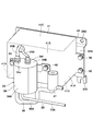
- FIG. 1 is a front view showing a hydraulic excavator according to a first embodiment of the present invention. It is a top view which shows an upper revolving body in the state which omitted a cab, a building cover, etc. It is a perspective view which expands from the diagonal upper side in the state which assembled the bracket, the cover, the urea water supply apparatus, the urea water filter, etc. It is a perspective view which expands and shows from diagonally lower side in the state which assembled the bracket, the cover, the urea water supply apparatus, the urea water filter. It is sectional drawing which shows typically the internal structure of a urea water filter. It is a circuit diagram which shows an exhaust-gas purification apparatus.
- FIG. 1 to FIG. 6 show a first embodiment of the present invention.
- a hydraulic excavator 1 includes a crawler-type lower traveling body 2 capable of self-running, and an upper revolving body 3 that is provided on the lower traveling body 2 so as to be capable of turning and constitutes a vehicle body together with the lower traveling body 2.
- the front revolving unit 3 is provided with a front device 4 that can be raised and lowered and that performs excavation work of earth and sand.
- the upper revolving unit 3 is provided on the rear side of the revolving frame 5 that forms the support structure, on the rear side of the revolving frame 5, and is provided on the left side of the front part of the revolving frame 5.
- the revolving frame 5 is erected on a bottom plate 5A made of a thick steel plate or the like extending in the front and rear directions, and on the bottom plate 5A, and forward and rear with a predetermined interval in the left and right directions.
- a bottom plate 5A made of a thick steel plate or the like extending in the front and rear directions, and on the bottom plate 5A, and forward and rear with a predetermined interval in the left and right directions.
- a purification device assembly 39 which will be described later, is attached to the rear surface side of the connecting plate 5G.
- the engine 9 is located in front of the counterweight 6 and is provided in a horizontally placed state on the turning frame 5 extending left and right.
- a cooling fan 9 ⁇ / b> A for supplying cooling air to a heat exchanger 11 described later is provided on the left side of the engine 9.
- a hydraulic pump 12 described later is provided on the right side of the engine 9.
- a water jacket 9 ⁇ / b> B through which cooling water for suppressing a temperature rise during operation is provided in the engine 9.
- a cooling water pump 9C for supplying cooling water is provided on the inflow side of the water jacket 9B.
- the water jacket 9B is connected to a heat exchanger 11 described later.
- the cooling water circulates between the water jacket 9B and the heat exchanger 11 by driving the cooling water pump 9C.
- a part of the cooling water (warm water) whose temperature has been increased by cooling the engine 9 is also supplied to the urea water filter 33 and the urea water supply device 25 through a cooling water supply passage 36 described later.
- an exhaust pipe 10 for discharging exhaust gas is connected to the engine 9 (see FIG. 2).
- the exhaust pipe 10 is formed as a metal pipe line extending leftward and rightward from the front position of the engine 9.
- the exhaust pipe 10 guides high-temperature exhaust gas discharged from the engine 9 to an exhaust gas aftertreatment device 16 which will be described later.
- the heat exchanger 11 is disposed on the left side of the engine 9.
- the heat exchanger 11 is provided so as to face the cooling fan 9 ⁇ / b> A of the engine 9.
- the heat exchanger 11 includes, for example, a radiator 11A that circulates in the water jacket 9B of the engine 9 and cools the heated coolant, an oil cooler that cools the working oil, and an intercooler that cools the air that the engine 9 sucks (all are Etc.).
- the hydraulic pump 12 is provided on the right side of the engine 9.
- the hydraulic pump 12 is driven by the engine 9.
- the hydraulic pump 12 uses hydraulic oil supplied from a hydraulic oil tank 13 described later as pressure oil to control various actuators provided in the lower traveling body 2, the front device 4, and the like (not shown). )
- the hydraulic oil tank 13 is located on the front side of the hydraulic pump 12 and is provided on the right side of the revolving frame 5.
- the hydraulic oil tank 13 stores hydraulic oil for driving each actuator.
- the fuel tank 14 is located on the front side of the hydraulic oil tank 13 and is provided in the turning frame 5.
- the exhaust gas purifying device 15 purifies the exhaust gas discharged from the engine 9 and is disposed on the upper side of the hydraulic pump 12, for example.
- the exhaust gas purification device 15 removes harmful substances in the exhaust gas discharged from the engine 9. Further, the exhaust gas purifying device 15 includes a silencer mechanism for reducing exhaust gas noise.
- the exhaust gas purification device 15 includes an exhaust gas aftertreatment device 16 having a urea selective reduction catalyst 19 and a urea water injection valve 21, which will be described later, a urea water tank 22, a urea water pipe 23, a urea water supply device 25, and a urea water filter. 33 is provided.
- the exhaust gas aftertreatment device 16 is connected to the outlet side of the exhaust pipe 10.
- the exhaust gas aftertreatment device 16 includes, for example, a cylindrical cylinder 17 extending in the front and rear directions, a first oxidation catalyst 18, a urea selective reduction catalyst 19, and a second oxidation catalyst provided in the cylinder 17. 20 and the urea water injection valve 21.
- the cylindrical body 17 is formed as a sealed container with both ends closed.
- An exhaust pipe 10 is connected to a front side portion that is upstream of the cylindrical body 17.
- the tubular body 17 is provided with a tail tube 17A located at a rear side portion on the downstream side.
- a first oxidation catalyst 18, a urea selective reduction catalyst 19, and a second oxidation catalyst 20 are arranged at intervals in the length direction.
- a urea water injection valve 21 is attached to the cylindrical body 17 so as to be positioned between the first oxidation catalyst 18 and the urea selective reduction catalyst 19.
- the first oxidation catalyst 18 is made of, for example, a ceramic cell-shaped cylinder, and has a large number of through holes formed in the axial direction thereof, and the inner surface is coated with a noble metal or the like.
- the first oxidation catalyst 18 oxidizes carbon monoxide (CO), hydrocarbon (HC), etc. contained in the exhaust gas by circulating the exhaust gas through each through hole at a predetermined temperature. Remove. Further, the particulate matter (PM) is also burned and removed as necessary.
- the urea selective reduction catalyst 19 is made of, for example, a ceramic cell-like cylinder, and has a large number of through holes formed in the axial direction thereof, and the inner surface is coated with a noble metal.
- the urea selective reduction catalyst 19 selectively reduces nitrogen oxide (NOx) contained in the exhaust gas discharged from the engine 9 with ammonia generated from the urea aqueous solution, and decomposes it into nitrogen and water.
- NOx nitrogen oxide
- the second oxidation catalyst 20 is made of a ceramic cell-like cylindrical body in substantially the same manner as the first oxidation catalyst 18 described above, and has a large number of through-holes formed in the axial direction and coated with a noble metal on the inner surface. ing. Thereby, the second oxidation catalyst 20 oxidizes residual ammonia remaining after reducing the nitrogen oxides by the urea selective reduction catalyst 19 and separates it into nitrogen and water.
- the urea water injection valve 21 is located between the first oxidation catalyst 18 and the urea selective reduction catalyst 19 and is attached to the cylindrical body 17.
- the urea water injection valve 21 injects a urea aqueous solution toward the exhaust gas flowing through the cylindrical body 17. That is, the urea water injection valve 21 is connected to a urea water tank 22 via a urea water pipe 23 described later, and the urea water as a reducing agent is located upstream of the urea selective reduction catalyst 19 and is located in the cylinder 17. To spray.
- the urea water tank 22 is provided on the revolving frame 5 as an example of an installation location, located in front of the fuel tank 14.
- the urea water tank 22 stores urea water as a reducing agent, and is connected to a urea water injection valve 21 via a urea water pipe 23 described later.
- the urea water in the urea water tank 22 is supplied to the urea water injection valve 21 through the urea water pipe 23 by driving a urea water supply device 25 described later.
- the urea water pipe line 23 connects between the urea water tank 22 and the urea water injection valve 21.
- the urea water pipe 23 is composed of, for example, a resin hose, a metal pipe, or both a resin hose and a metal pipe, and urea water stored in the urea water tank 22 is injected with urea water. It circulates toward the valve 21.
- a urea water supply device 25 and a urea water filter 33 which will be described later, are provided.
- the urea water conduit 23 is connected to the urea water tank 22 at one end on the upstream side when supplying urea water, and the other end on the downstream side is urea which will be described later.
- a tank side pipe line portion 23A connected to the lower part of the filter case 34 of the water filter 33, and a supply apparatus side pipe line part having one end connected to the upper part of the filter case 34 and the other end connected to the urea water supply device 25.
- the supply device side pipe line portion 23 ⁇ / b> B can be formed short by arranging the urea water supply device 25 and the urea water filter 33 close to each other as a part of the purification device assembly 39.
- the urea water filter 33 is arranged upstream of the urea water supply device 25 in the urea water supply direction.
- the urea water filter 33 performs an operation of returning the urea water remaining in the urea water pipe line 23, the urea water filter 33, and the like to the urea water tank 22. Therefore, air and urea water are mixed in the supply device side pipe line section 23 ⁇ / b> B and the urea water filter 33 between the urea water supply device 25 and the urea water tank 22.
- the urea water supply device 25 sucks up urea water from the urea water tank 22, but at that time, the urea water and air are sucked up simultaneously. If the urea water and the air are sucked up at the same time as described above, there is a possibility that a malfunction (for example, destabilization of the supply pressure of the urea water) may occur due to the engagement of the air with the urea water pump 27.
- urea water and air can be separated by devising a connection position between the tank side pipe section 23A and the supply apparatus side pipe section 23B as described later.
- the separation effect of urea water and air in the urea water filter 33 does not reach the supply device side pipe section 23B.
- the mixed state of the air and the urea water in the supply device side conduit portion 23B can be suppressed as much as possible by forming the supply device side conduit portion 23B short.
- the urea water pump 27 can prevent problems due to air entrapment.
- bracket 24 the urea water supply device 25, and the urea water filter 33, which are characteristic portions of the present embodiment, and the urea water supply device 25 and the urea water filter 33 are attached to the revolving frame 5 using the bracket 24.
- the structure will be described.
- the bracket 24 is attached to the rear surface of the connecting plate 5G of the revolving frame 5.
- the bracket 24 has a urea water supply device 25 attached to the connecting plate 5G.
- the bracket 24 includes a horizontally-long rectangular supply device mounting plate 24A, an upper mounting plate 24B bent in a crank shape on the upper side of the supply device mounting plate 24A, and a longitudinal direction of the lower side of the supply device mounting plate 24A.
- the lower mounting plate 24 ⁇ / b> C is provided by bending at both ends in a crank shape.
- a urea water supply device 25 and a cover 31 are attached to the supply device mounting plate 24 ⁇ / b> A of the bracket 24.
- the upper mounting plate 24B and each lower mounting plate 24C of the bracket 24 are mounted on the rear surface of the connecting plate 5G using bolts (not shown).
- the urea water supply device 25 is provided in the middle of the urea water conduit 23, that is, between the supply device side conduit portion 23B and the injection valve side conduit portion 23C.
- the urea water supply device 25 supplies urea water from the urea water tank 22 toward the urea water injection valve 21.
- the urea water supply device 25 is located downstream of the casing 26, the urea water pump 27 (see FIG. 6) built in the casing 26, and the urea water pump 27 when supplying the urea water to the casing 26.
- the built-in filter 28 and a pressure sensor 29 provided in the casing 26 are located downstream of the built-in filter 28.
- the casing 26 is detachably attached to the supply device mounting plate 24A of the bracket 24 using bolts (not shown).
- the casing 26 passes through a urea water pump 27 and a built-in filter 28, and a main passage 26 ⁇ / b> A that connects the supply device side pipe portion 23 ⁇ / b> B and the injection valve side pipe portion 23 ⁇ / b> C of the urea water pipe 23 and a built-in filter 28.
- a return passage 26B branched from the main passage 26A, which is located on the downstream side when supplying urea water.
- a heater passage 26 ⁇ / b> C is provided in the casing 26 so as to pass, for example, the vicinity of the urea water pump 27 and the built-in filter 28.
- a urea water inlet joint 26D serving as an inlet of the main passage 26A
- a urea water outlet joint 26E serving as an outlet of the main passage 26A
- a urea water return joint 26F serving as an outlet of the return passage 26B
- a cooling water inlet joint 26G serving as an inlet of the heater passage 26C
- a cooling water outlet joint 26H serving as an outlet of the heater passage 26C are provided.
- the other end of the supply device side pipe section 23B that forms the urea water pipe line 23 is connected to the urea water inlet joint 26D.
- One end of an injection valve side pipe line portion 23C is connected to the urea water outlet joint 26E.
- One end of a urea water return passage 30 for returning urea water to the urea water tank 22 is connected to the urea water return joint 26F.
- the other end of a second passage 36B of a cooling water supply passage 36 to be described later is connected to the cooling water inlet joint 26G.
- One end of a cooling water return passage 38 to be described later is connected to the cooling water outlet joint 26H.
- the casing 26 is provided with a filter mounting space 26J (see FIG. 4) for mounting the built-in filter 28.
- the filter mounting space 26J is formed to open downward. Thereby, the built-in filter 28 can be attached to the filter mounting space 26J from below, and can be removed downward.
- the urea water pump 27 is disposed upstream of the main passage 26A when supplying urea water.
- the urea water pump 27 is driven by, for example, an electric motor (not shown) to pump the urea water in the urea water tank 22 to the urea water injection valve 21 through the urea water conduit 23.
- the built-in filter 28 is located in the main passage 26A, located between the urea water pump 27 and the branch point of the return passage 26B.
- the built-in filter 28 can capture foreign matters mixed in the urea water supplied toward the urea water injection valve 21.
- the built-in filter 28 when the built-in filter 28 is attached to the casing 26, it can be attached from the lower side opened to the filter mounting space 26J.
- the cover 31 covering the urea water supply device 25 has the opening 31C that opens downward, the built-in filter 28 can be easily attached and detached through the opening 31C.
- the cover 31 is attached to the bracket 24 so as to cover the urea water supply device 25.
- the cover 31 is disposed at a position sandwiching the urea water supply device 25 from the lateral direction, and sandwiches the urea water supply device 25 with a pair of side plates 31A attached to the supply device mounting plate 24A of the bracket 24 using bolts 32.
- the filter mounting plate 31B is located on the opposite side of the bracket 24 and provided over the tip of each side plate 31A.
- the cover 31 covers the periphery of the urea water supply device 25, and the upper side and the lower side are opened.
- an opening 31 ⁇ / b> C for allowing the built-in filter 28 to pass when the built-in filter 28 is attached to and detached from the urea water supply device 25 is provided below the cover 31. ing. Accordingly, the built-in filter 28 can be easily attached and detached through the opening 31C.
- the urea water filter 33 is attached to the filter attachment plate 31B of the cover 31.
- the urea water filter 33 is provided between the urea water tank 22 and the urea water supply device 25 in the middle of the urea water pipe 23 and captures foreign matters mixed in the urea water.
- the exhaust gas purifying device 15 by providing the two filters, the built-in filter 28 and the urea water filter 33 described above, foreign matters mixed in the urea water can be reliably captured.
- the urea water filter 33 includes, for example, a filter case 34 formed of a cylindrical container, and a filter element 35 that is provided in the filter case 34 and captures foreign matters mixed in the urea water.
- the filter case 34 includes a circular cylindrical body 34A, an upper surface plate 34B, and a lower surface plate 34C.
- the filter case 34 is detachably attached to the filter attachment plate 31 ⁇ / b> B of the cover 31 using bolts 40. Thereby, the urea water filter 33 can be replaced by loosening the bolt 40.
- the lower surface plate 34C of the filter case 34 is provided with a urea water inlet joint 34E that opens to the lower portion of the urea water storage chamber 34D.
- the upper surface plate 34B of the filter case 34 is provided with a urea water outlet joint 34F that opens to an upper portion of the urea water storage chamber 34D.
- the other end of the tank side pipe section 23A constituting the urea water pipe line 23 is connected to the urea water inlet joint 34E.
- the other end of the tank side pipe portion 23 ⁇ / b> A opens to the lower part of the urea water storage chamber 34 ⁇ / b> D of the filter case 34.
- one end of a supply device side pipe line portion 23 ⁇ / b> B constituting the urea water pipe line 23 is connected to the urea water outlet joint 34 ⁇ / b> F.
- one end of supply device side pipe line part 23B is opened to the upper part of urea water storage room 34D.
- the filter case 34 is provided with a heater passage 34G so as to pass in the vicinity of the filter element 35, for example.
- a cooling water inlet joint 34 ⁇ / b> H is provided on the lower surface plate 34 ⁇ / b> C of the filter case 34.
- the upper surface plate 34B of the filter case 34 is provided with a cooling water outlet joint 34J.
- the other end of a first passage 36A of a cooling water supply passage 36 described later is connected to the cooling water inlet joint 34H, and one end of a second passage 36B is connected to the cooling water outlet joint 34J.
- the urea water filter 33 configured in this manner allows urea water from the urea water tank 22 to flow into the urea water storage chamber 34D from below the urea water storage chamber 34D.
- urea water flows into the urea water storage chamber 34D so as not to entrain the internal air, and most of the air in the urea water storage chamber 34D is directed to the supply device side pipe section 23B side. Spill.
- the urea water filter 33 can cause the urea water not mixed with air to flow out to the supply device side pipe section 23B side.
- the urea water that has flowed into the urea water storage chamber 34D passes through the filter element 35, so that foreign matters are removed and cleaned. Thereby, the urea water filter 33 can flow out clean urea water to the supply apparatus side pipe line part 23B side.
- the cooling water supply passage 36 is provided across the outlet side of the water jacket 9 ⁇ / b> B of the engine 9, the urea water supply device 25, and the urea water filter 33.
- the cooling water supply passage 36 is provided in the first passage 36A that connects the outlet side of the water jacket 9B and the cooling water inlet joint 34H of the filter case 34, the cooling water outlet joint 34J, and the casing 26 of the urea water supply device 25.
- the second passage 36B is connected to the cooling water inlet joint 26G.
- the cooling water control valve 37 is attached to the cover 31 in the middle of the first passage 36 ⁇ / b> A of the cooling water supply passage 36.
- the cooling water control valve 37 is opened when the urea water in the urea water supply device 25 and the urea water filter 33 is frozen or freezing. Thereby, the cooling water control valve 37 supplies the cooling water heated by cooling the engine 9 to the urea water supply device 25 and the urea water filter 33.
- the cooling water return passage 38 can return the cooling water that has warmed the urea water supply device 25 and the urea water filter 33 to the water jacket 9B.
- the cooling water return passage 38 connects the cooling water outlet joint 26H of the casing 26 and the inlet side of the water jacket 9B.
- the purification device assembly 39 is configured by assembling the bracket 24, the urea water supply device 25, the cover 31, the urea water filter 33, and the cooling water control valve 37 described above. Yes. Since this purification device assembly 39 can be assembled at a place different from the main assembly line, the workability at the time of assembly can be improved.
- the hydraulic excavator 1 has the above-described configuration, and the operation thereof will be described next.
- the operator gets on the cab 7 and operates the engine 9.
- the operator can run the hydraulic excavator 1 by operating a travel operation lever / pedal (not shown) disposed in the cab 7.
- the operator can perform excavation work of earth and sand using the front device 4 by operating an operation lever (not shown) for work.
- the exhaust gas discharged from the engine 9 passes through the exhaust pipe 10 and the exhaust gas aftertreatment device 16 and is discharged into the atmosphere.
- carbon monoxide (CO), hydrocarbon (HC), etc. contained in the exhaust gas are oxidized and removed by the first oxidation catalyst 18 provided in the exhaust gas aftertreatment device 16. Further, particulate matter (PM) is burned and removed as necessary.
- urea water is injected toward the exhaust gas from the urea water injection valve 21, and the nitrogen oxide is decomposed into nitrogen and water by the urea selective reduction catalyst 19.
- the second oxidation catalyst 20 oxidizes residual ammonia and separates it into nitrogen and water, so that exhaust gas that has been sufficiently purified can be discharged into the atmosphere.
- the urea water pump 27 of the urea water supply device 25 is driven to suck up the urea water in the urea water tank 22 through the urea water pipe 23.
- the urea water flowing through the tank side pipe part 23A of the urea water pipe line 23 passes through the urea water filter 33, so that the foreign matter is removed and cleaned by the filter element 35 to the supply apparatus side pipe part 23B. leak.
- the urea water from the tank side pipe section 23A flows from the lower part of the urea water storage chamber 34D.
- urea water can be made to flow into urea water storage chamber 34D so that internal air may not be caught, and urea water and air can be separated into two layers of upper and lower directions.
- the urea water that has flowed into the urea water storage chamber 34D passes through the filter element 35 and is purified, and then flows out to the supply device side pipe section 23B.
- the supply device side conduit portion 23B of the urea water conduit 23 is formed short by arranging the urea water supply device 25 and the urea water filter 33 close as a part of the purification device assembly 39. Thereby, the mixed state of the air and urea water in the supply apparatus side pipe line part 23B can be suppressed as much as possible.
- the urea water supplied to the urea water supply device 25 through the supply device side pipe section 23B flows into the main passage 26A and is pumped from the urea water pump 27.
- the urea water that has flowed into the main passage 26A is suppressed from being mixed with air, the urea water can be stably supplied without causing a problem due to air biting.
- the urea water pumped from the urea water pump 27 passes through the built-in filter 28, so that foreign matters are removed and further purified.
- the purified urea water is supplied to the urea water injection valve 21 through the injection valve side pipe section 23C.
- the urea water that has not been supplied to the urea water injection valve 21 is returned to the urea water tank 22 through the return passage 26 ⁇ / b> B and the urea water return passage 30.
- the urea water supply device 25 is provided in the middle of the urea water pipe 23 and supplies urea water from the urea water tank 22 toward the urea water injection valve 21.
- a bracket 24 for attaching the urea water supply device 25 is attached to the turning frame 5 of the upper turning body 3.
- a cover 31 that covers the urea water supply device 25 is attached to the bracket 24.
- the urea water filter 33 that is provided in the middle of the urea water pipe 23 and captures foreign matters mixed in the urea water is configured to be attached to the cover 31.
- the bracket 24, the urea water supply device 25, the cover 31, the urea water filter 33, and the like can be formed as one purification device assembly 39.
- the urea water supply device 25 and the urea water filter 33 can be attached to the revolving frame 5 as the purification device assembly 39.
- the urea water supply device 25 and the urea water filter 33 can be easily attached to the revolving frame 5 and the maintainability of the urea water filter 33 can be improved.
- the urea water filter 33 includes a filter case 34 having a urea water storage chamber 34D that stores urea water therein, and a filter element 35 that is provided in the urea water storage chamber 34D of the filter case 34 and captures foreign matters mixed in the urea water. And.
- the urea water pipe 23 has one end connected to the urea water tank 22 and the other end connected to the lower part of the filter case 34, a tank side pipe part 23A, one end connected to the upper part of the filter case 34, and the other end And a supply device side pipe section 23 ⁇ / b> B connected to the urea water supply device 25.
- the urea water from the urea water tank 22 can flow into the urea water storage chamber 34D from the lower part of the urea water storage chamber 34D. That is, since urea water flows into the urea water storage chamber 34D from below so as not to entrain the internal air, the air in the urea water storage chamber 34D is pushed up by the inflowing urea water and supplied to the supply device side pipe. It flows out to the road part 23B side. Thereby, the urea water filter 33 can supply the urea water in which the air is not mixed to the supply device side pipe section 23B side after the air has flowed out.
- the urea water supply device 25 is detachably provided with a built-in filter 28 that captures foreign matters mixed in the urea water.
- a built-in filter 28 that captures foreign matters mixed in the urea water.
- an opening 31 ⁇ / b> C for allowing the built-in filter 28 to pass when the built-in filter 28 is attached to and detached from the urea water supply device 25 is provided below the cover 31, an opening 31 ⁇ / b> C for allowing the built-in filter 28 to pass when the built-in filter 28 is attached to and detached from the urea water supply device 25 is provided. Accordingly, the built-in filter 28 can be easily attached and detached through the opening 31C.
- FIG. 7 shows a second embodiment of the present invention.
- a feature of the present embodiment is that the cover is configured to open only to the lower side where the opening is provided in a state of being attached to the bracket.
- the same components as those in the first embodiment described above are denoted by the same reference numerals, and the description thereof is omitted.
- the cover 41 is attached to the bracket 24 so as to cover the urea water supply device 25.
- the cover 41 is disposed at a position sandwiching the urea water supply device 25 from the lateral direction, and sandwiches the urea water supply device 25 with a pair of side plates 41A attached to the supply device mounting plate 24A of the bracket 24 using bolts 32.
- the filter mounting plate 41B provided over the tip of each side plate 41A, and the upper side of each side plate 41A and the filter mounting plate 41B so as to cover the upper side of the urea water supply device 25.
- an upper surface plate 41 ⁇ / b> C whereby, the cover 41 is attached to the bracket 24, and only the lower side where the opening 41D is provided is open.
- the cover 41 covers the upper side of the urea water supply device 25 by the upper surface plate 41C, the urea water supply device 25 and the hose connected to the urea water supply device 25 are covered. Can be protected.
- FIG. 8 shows a third embodiment of the present invention.
- the feature of this embodiment is that the cover is configured to open sideways and downward.
- the same components as those in the first embodiment described above are denoted by the same reference numerals, and the description thereof is omitted.
- the cover 51 is attached to the bracket 24 so as to cover the urea water supply device 25.
- the cover 51 is located on the opposite side of the bracket 24 with the side plate 51A facing one side in the lateral direction of the urea water supply device 25 and the urea water supply device 25 interposed therebetween, and a filter attached to the tip of the side plate 51A.
- the plate 51B is constituted by a side plate 51A and an upper plate 51C provided on the upper part of the filter mounting plate 51B so as to cover the upper side of the urea water supply device 25. Thereby, the cover 51 is attached to the bracket 24, and the other side in the lateral direction and the lower side where the opening 51D is provided are opened.
- the present invention is not limited to this, and for example, a particulate matter removal filter (DPF) may be provided in the cylinder of the exhaust gas aftertreatment device and located downstream of the first oxidation catalyst.
- This particulate matter removal filter purifies exhaust gas by collecting particulate matter (PM) in exhaust gas discharged from the engine, and burning and removing it.
- the hydraulic excavator 1 including the crawler type lower traveling body 2 is described as an example of the construction machine.
- the present invention is not limited to this, and may be applied to, for example, a hydraulic excavator provided with a wheel-type lower traveling body. Besides, it can be widely applied to other construction machines such as hydraulic cranes.
Abstract
The present invention has a urea water supply device (25) which is provided in the middle of a urea water duct (23) and which supplies urea water to a urea water injection valve (21) from a urea water tank (22). A bracket (24) for attaching the urea water supply device (25) is attached to a revolving frame (5) of an upper revolving body (3). A cover (31) covering the urea water supply device (25) is attached to said bracket (24). On top of which, a urea water filter (33), which is provided in the middle of the urea water duct (23) and traps foreign material that is mixed in with the urea water, is configured so as to be attached to the cover (31).
Description
本発明は、例えばエンジンの排気ガスを浄化する排気ガス浄化装置を備えた油圧ショベル等の建設機械に関する。
The present invention relates to a construction machine such as a hydraulic excavator provided with an exhaust gas purification device that purifies exhaust gas of an engine, for example.
一般に、建設機械としての油圧ショベルは、自走が可能な車体と、車体に設けられたエンジンと、エンジンから排出された排気ガスを浄化する排気ガス浄化装置とを有している。また、排気ガス浄化装置は、エンジンの排気管に接続され排気ガス中の窒素酸化物を除去する尿素選択還元触媒と、還元剤である尿素水を尿素選択還元触媒の上流側に噴射する尿素水噴射弁と、尿素水噴射弁に供給される尿素水を貯える尿素水タンクと、尿素水タンクと尿素水噴射弁との間を接続する尿素水管路と、尿素水管路の途中に設けられ尿素水タンクから尿素水噴射弁に向けて尿素水を供給する尿素水供給装置と、尿素水管路の途中に設けられ尿素水に混入した異物を捕捉する尿素水フィルタとを備えている(特許文献1)。特許文献1では、尿素水タンク、尿素水供給装置および尿素水フィルタが一体的に組立てられている。
Generally, a hydraulic excavator as a construction machine has a self-propelled vehicle body, an engine provided in the vehicle body, and an exhaust gas purification device that purifies exhaust gas discharged from the engine. Further, the exhaust gas purification device includes a urea selective reduction catalyst that is connected to an exhaust pipe of an engine and removes nitrogen oxides in the exhaust gas, and urea water that injects urea water as a reducing agent upstream of the urea selective reduction catalyst. An injection valve, a urea water tank for storing urea water supplied to the urea water injection valve, a urea water pipe connecting the urea water tank and the urea water injection valve, and urea water provided in the middle of the urea water pipe A urea water supply device that supplies urea water from the tank toward the urea water injection valve, and a urea water filter that is provided in the middle of the urea water pipe and captures foreign matters mixed in the urea water (Patent Document 1). . In Patent Document 1, a urea water tank, a urea water supply device, and a urea water filter are integrally assembled.
ところで、特許文献1によるものでは、尿素水タンク、尿素水供給装置および尿素水フィルタを一体的に組立てている。この場合、尿素水タンクと尿素水供給装置には、多くのホースや電線がそれぞれ接続されている。従って、尿素水フィルタは、各ホース、電線の奥に隠れた状態になるから、エレメントの交換作業、清掃作業、点検作業等のメンテナンスに手間を要してしまうという問題がある。
By the way, according to Patent Document 1, a urea water tank, a urea water supply device, and a urea water filter are integrally assembled. In this case, many hoses and electric wires are connected to the urea water tank and the urea water supply device, respectively. Therefore, since the urea water filter is hidden in the back of each hose and electric wire, there is a problem that it takes time for maintenance such as element replacement work, cleaning work, and inspection work.
本発明は上述した従来技術の問題に鑑みなされたもので、本発明の目的は、尿素水供給装置と尿素水フィルタを車体に対して容易に取付けることができる上に、尿素水フィルタのメンテナンス性を向上できるようにした建設機械を提供することにある。
The present invention has been made in view of the above-described problems of the prior art, and an object of the present invention is to easily attach the urea water supply device and the urea water filter to the vehicle body, and to maintain the urea water filter. It is to provide a construction machine that can improve the performance.
本発明は、自走が可能な車体と、前記車体に設けられたエンジンと、前記エンジンから排出された排気ガスを浄化する排気ガス浄化装置とを有し、前記排気ガス浄化装置は、前記エンジンの排気管に接続され前記排気ガス中の窒素酸化物を除去する尿素選択還元触媒と、還元剤である尿素水を前記尿素選択還元触媒の上流側に噴射する尿素水噴射弁と、前記尿素水噴射弁に供給される尿素水を貯える尿素水タンクと、前記尿素水タンクと前記尿素水噴射弁との間を接続する尿素水管路と、前記尿素水管路の途中に設けられ前記尿素水タンクから前記尿素水噴射弁に向けて尿素水を供給する尿素水供給装置と、前記尿素水管路の途中で前記尿素水タンクと前記尿素水供給装置との間に設けられ前記尿素水に混入した異物を捕捉する尿素水フィルタとを備えてなる建設機械において、前記車体には、前記尿素水供給装置を取付けるためのブラケットが取付けられ、前記ブラケットには、前記尿素水供給装置を覆うカバーが取付けられ、前記尿素水フィルタは、前記カバーに取付けられている。
The present invention has a self-propelled vehicle body, an engine provided in the vehicle body, and an exhaust gas purification device that purifies exhaust gas discharged from the engine, and the exhaust gas purification device includes the engine A urea selective reduction catalyst connected to the exhaust pipe for removing nitrogen oxides in the exhaust gas, a urea water injection valve for injecting urea water as a reducing agent upstream of the urea selective reduction catalyst, and the urea water A urea water tank for storing urea water to be supplied to the injection valve, a urea water pipe connecting between the urea water tank and the urea water injection valve, and provided in the middle of the urea water pipe from the urea water tank A urea water supply device that supplies urea water toward the urea water injection valve, and a foreign matter mixed in the urea water that is provided between the urea water tank and the urea water supply device in the middle of the urea water pipeline. Captured urea water fi A bracket for attaching the urea water supply device is attached to the vehicle body, and a cover for covering the urea water supply device is attached to the bracket, and the urea water filter Is attached to the cover.
本発明によれば、尿素水供給装置と尿素水フィルタを車体に対して容易に取付けることができる上に、尿素水フィルタのメンテナンス性を向上することができる。
According to the present invention, the urea water supply device and the urea water filter can be easily attached to the vehicle body, and the maintainability of the urea water filter can be improved.
以下、本発明の実施の形態に係る建設機械の代表例として、クローラ式の油圧ショベルを例に挙げ、添付図面に従って詳細に説明する。
Hereinafter, as a representative example of the construction machine according to the embodiment of the present invention, a crawler type hydraulic excavator will be taken as an example and described in detail with reference to the accompanying drawings.
まず、図1ないし図6は本発明の第1の実施の形態を示している。図1において、油圧ショベル1は、自走が可能なクローラ式の下部走行体2と、下部走行体2上に旋回が可能に設けられ、下部走行体2と共に車体を構成する上部旋回体3と、上部旋回体3の前側に俯仰の動作が可能に設けられ、土砂の掘削作業等を行うフロント装置4とにより構成されている。
First, FIG. 1 to FIG. 6 show a first embodiment of the present invention. In FIG. 1, a hydraulic excavator 1 includes a crawler-type lower traveling body 2 capable of self-running, and an upper revolving body 3 that is provided on the lower traveling body 2 so as to be capable of turning and constitutes a vehicle body together with the lower traveling body 2. The front revolving unit 3 is provided with a front device 4 that can be raised and lowered and that performs excavation work of earth and sand.
上部旋回体3は、支持構造体をなす旋回フレーム5と、旋回フレーム5の後側に設けられ、フロント装置4との重量バランスをとるカウンタウエイト6と、旋回フレーム5の前部左側に設けられオペレータが搭乗するキャブ7と、カウンタウエイト6の前側に設けられ、内部に後述のエンジン9、熱交換器11、排気ガス浄化装置15等を収容する建屋カバー8とを備えている。
The upper revolving unit 3 is provided on the rear side of the revolving frame 5 that forms the support structure, on the rear side of the revolving frame 5, and is provided on the left side of the front part of the revolving frame 5. A cab 7 on which an operator is boarded and a building cover 8 that is provided on the front side of the counterweight 6 and accommodates an engine 9, a heat exchanger 11, an exhaust gas purifying device 15, and the like, which will be described later, are provided therein.
図2に示すように、旋回フレーム5は、前,後方向に延びる厚肉な鋼板等からなる底板5Aと、底板5A上に立設され、左,右方向に所定の間隔をもって前,後方向に延びた左縦板5B,右縦板5Cと、各縦板5B,5Cの左,右方向に間隔をもって配置され、前,後方向に延びた左サイドフレーム5D,右サイドフレーム5Eと、底板5A、左縦板5Bから左方向に張出した先端部に左サイドフレーム5Dを支持し、また右縦板5Cから右方向に張出した先端部に右サイドフレーム5Eを支持する複数本の張出ビーム5Fと、エンジン9の前側に位置して左縦板5Bと右縦板5Cとの間を連結して底板5A上に立設された連結板5Gとを含んで構成されている。連結板5Gの後面側には、後述する浄化装置組立体39が取付けられている。
As shown in FIG. 2, the revolving frame 5 is erected on a bottom plate 5A made of a thick steel plate or the like extending in the front and rear directions, and on the bottom plate 5A, and forward and rear with a predetermined interval in the left and right directions. Left vertical plate 5B, right vertical plate 5C, left and right sides of each vertical plate 5B, 5C spaced apart, left and right side frame 5D, right side frame 5E, and bottom plate 5A, a plurality of overhanging beams that support the left side frame 5D at the front end protruding from the left vertical plate 5B in the left direction and support the right side frame 5E at the front end protruding from the right vertical plate 5C in the right direction. 5F and a connecting plate 5G that is positioned on the front side of the engine 9 and connects between the left vertical plate 5B and the right vertical plate 5C and is erected on the bottom plate 5A. A purification device assembly 39, which will be described later, is attached to the rear surface side of the connecting plate 5G.
エンジン9は、カウンタウエイト6の前側に位置して旋回フレーム5上に左,右方向に延びる横置き状態で設けられている。このエンジン9の左側には、後述の熱交換器11に冷却風を供給するための冷却ファン9Aが設けられている。一方、エンジン9の右側には、後述の油圧ポンプ12が設けられている。
The engine 9 is located in front of the counterweight 6 and is provided in a horizontally placed state on the turning frame 5 extending left and right. On the left side of the engine 9, a cooling fan 9 </ b> A for supplying cooling air to a heat exchanger 11 described later is provided. On the other hand, a hydraulic pump 12 described later is provided on the right side of the engine 9.
図6に示すように、エンジン9内には、稼働時の温度上昇を抑えるための冷却水が流通するウォータジャケット9Bが設けられている。このウォータジャケット9Bの流入側には、冷却水を供給するための冷却水ポンプ9Cが設けられている。ウォータジャケット9Bは、後述の熱交換器11に接続されている。冷却水は、冷却水ポンプ9Cの駆動によりウォータジャケット9Bと熱交換器11との間で循環流通している。また、エンジン9を冷却して温度上昇した冷却水(温水)の一部は、後述の冷却水供給通路36を通じて尿素水フィルタ33と尿素水供給装置25にも供給される。
As shown in FIG. 6, a water jacket 9 </ b> B through which cooling water for suppressing a temperature rise during operation is provided in the engine 9. A cooling water pump 9C for supplying cooling water is provided on the inflow side of the water jacket 9B. The water jacket 9B is connected to a heat exchanger 11 described later. The cooling water circulates between the water jacket 9B and the heat exchanger 11 by driving the cooling water pump 9C. A part of the cooling water (warm water) whose temperature has been increased by cooling the engine 9 is also supplied to the urea water filter 33 and the urea water supply device 25 through a cooling water supply passage 36 described later.
さらに、エンジン9には、排気ガスを排出するための排気管10が接続されている(図2参照)。この排気管10は、エンジン9の前側位置を左,右方向に延びた金属製の管路として形成されている。排気管10は、エンジン9から排出された高温の排気ガスを後述の排気ガス後処理装置16へと導く。
Furthermore, an exhaust pipe 10 for discharging exhaust gas is connected to the engine 9 (see FIG. 2). The exhaust pipe 10 is formed as a metal pipe line extending leftward and rightward from the front position of the engine 9. The exhaust pipe 10 guides high-temperature exhaust gas discharged from the engine 9 to an exhaust gas aftertreatment device 16 which will be described later.
熱交換器11は、エンジン9の左側に配設されている。この熱交換器11は、エンジン9の冷却ファン9Aに対面して設けられている。熱交換器11は、例えばエンジン9のウォータジャケット9B内を流通して加温された冷却水を冷却するラジエータ11A、作動油を冷却するオイルクーラ、エンジン9が吸込む空気を冷却するインタクーラ(いずれも図示せず)等により構成されている。
The heat exchanger 11 is disposed on the left side of the engine 9. The heat exchanger 11 is provided so as to face the cooling fan 9 </ b> A of the engine 9. The heat exchanger 11 includes, for example, a radiator 11A that circulates in the water jacket 9B of the engine 9 and cools the heated coolant, an oil cooler that cools the working oil, and an intercooler that cools the air that the engine 9 sucks (all are Etc.).
油圧ポンプ12は、エンジン9の右側に位置して設けられている。この油圧ポンプ12は、エンジン9によって駆動される。これにより、油圧ポンプ12は、後述の作動油タンク13から供給される作動油を圧油として、下部走行体2、フロント装置4等に設けられた各種アクチュエータを制御する制御弁装置(図示せず)に向け吐出する。
The hydraulic pump 12 is provided on the right side of the engine 9. The hydraulic pump 12 is driven by the engine 9. As a result, the hydraulic pump 12 uses hydraulic oil supplied from a hydraulic oil tank 13 described later as pressure oil to control various actuators provided in the lower traveling body 2, the front device 4, and the like (not shown). )
作動油タンク13は、油圧ポンプ12の前側に位置して旋回フレーム5の右側に設けられている。この作動油タンク13は、各アクチュエータを駆動するための作動油を貯えている。一方、燃料タンク14は、作動油タンク13の前側に位置して旋回フレーム5に設けられている。
The hydraulic oil tank 13 is located on the front side of the hydraulic pump 12 and is provided on the right side of the revolving frame 5. The hydraulic oil tank 13 stores hydraulic oil for driving each actuator. On the other hand, the fuel tank 14 is located on the front side of the hydraulic oil tank 13 and is provided in the turning frame 5.
次に、本実施の形態の特徴部分である排気ガス浄化装置15の構成について詳しく説明する。
Next, the configuration of the exhaust gas purification device 15 that is a characteristic part of the present embodiment will be described in detail.
排気ガス浄化装置15は、エンジン9から排出された排気ガスを浄化するもので、例えば油圧ポンプ12の上側に配設されている。排気ガス浄化装置15は、エンジン9から排出される排気ガス中の有害物質を除去する。また、排気ガス浄化装置15は、排気ガスの騒音を低減するための消音機構を備えている。そして、排気ガス浄化装置15は、後述する尿素選択還元触媒19および尿素水噴射弁21を有する排気ガス後処理装置16、尿素水タンク22、尿素水管路23、尿素水供給装置25、尿素水フィルタ33を備えている。
The exhaust gas purifying device 15 purifies the exhaust gas discharged from the engine 9 and is disposed on the upper side of the hydraulic pump 12, for example. The exhaust gas purification device 15 removes harmful substances in the exhaust gas discharged from the engine 9. Further, the exhaust gas purifying device 15 includes a silencer mechanism for reducing exhaust gas noise. The exhaust gas purification device 15 includes an exhaust gas aftertreatment device 16 having a urea selective reduction catalyst 19 and a urea water injection valve 21, which will be described later, a urea water tank 22, a urea water pipe 23, a urea water supply device 25, and a urea water filter. 33 is provided.
排気ガス後処理装置16は、排気管10の出口側に接続されている。この排気ガス後処理装置16は、例えば前,後方向に延びる円筒状の筒体17と、筒体17内に設けられた第1の酸化触媒18、尿素選択還元触媒19、第2の酸化触媒20および尿素水噴射弁21とを含んで構成されている。
The exhaust gas aftertreatment device 16 is connected to the outlet side of the exhaust pipe 10. The exhaust gas aftertreatment device 16 includes, for example, a cylindrical cylinder 17 extending in the front and rear directions, a first oxidation catalyst 18, a urea selective reduction catalyst 19, and a second oxidation catalyst provided in the cylinder 17. 20 and the urea water injection valve 21.
筒体17は、両端が閉塞された密閉容器として形成されている。筒体17の上流側となる前側部位には排気管10が接続されている。一方、筒体17には、下流側となる後側部位に位置して尾管17Aが設けられている。筒体17内には、第1の酸化触媒18、尿素選択還元触媒19および第2の酸化触媒20が長さ方向に間隔をもって配置されている。また、筒体17には、第1の酸化触媒18と尿素選択還元触媒19との間に位置して尿素水噴射弁21が取付けられている。
The cylindrical body 17 is formed as a sealed container with both ends closed. An exhaust pipe 10 is connected to a front side portion that is upstream of the cylindrical body 17. On the other hand, the tubular body 17 is provided with a tail tube 17A located at a rear side portion on the downstream side. In the cylinder 17, a first oxidation catalyst 18, a urea selective reduction catalyst 19, and a second oxidation catalyst 20 are arranged at intervals in the length direction. Further, a urea water injection valve 21 is attached to the cylindrical body 17 so as to be positioned between the first oxidation catalyst 18 and the urea selective reduction catalyst 19.
第1の酸化触媒18は、例えばセラミックス製のセル状筒体からなり、その軸方向には多数個の貫通孔が形成され、内面に貴金属等がコーティングされている。そして、第1の酸化触媒18は、所定の温度下で各貫通孔に排気ガスを流通させることにより、この排気ガスに含まれる一酸化炭素(CO)、炭化水素(HC)等を酸化して除去する。また、必要に応じて粒子状物質(PM)も燃焼除去する。
The first oxidation catalyst 18 is made of, for example, a ceramic cell-shaped cylinder, and has a large number of through holes formed in the axial direction thereof, and the inner surface is coated with a noble metal or the like. The first oxidation catalyst 18 oxidizes carbon monoxide (CO), hydrocarbon (HC), etc. contained in the exhaust gas by circulating the exhaust gas through each through hole at a predetermined temperature. Remove. Further, the particulate matter (PM) is also burned and removed as necessary.
尿素選択還元触媒19は、例えばセラミックス製のセル状筒体からなり、その軸方向には多数の貫通孔が形成され、内面に貴金属がコーティングされている。この尿素選択還元触媒19は、エンジン9から排出される排気ガスに含まれる窒素酸化物(NOx)を、尿素水溶液から生成されたアンモニアによって選択的に還元反応させ、窒素と水に分解する。
The urea selective reduction catalyst 19 is made of, for example, a ceramic cell-like cylinder, and has a large number of through holes formed in the axial direction thereof, and the inner surface is coated with a noble metal. The urea selective reduction catalyst 19 selectively reduces nitrogen oxide (NOx) contained in the exhaust gas discharged from the engine 9 with ammonia generated from the urea aqueous solution, and decomposes it into nitrogen and water.
第2の酸化触媒20は、前述した第1の酸化触媒18とほぼ同様に、セラミックス製のセル状筒体からなり、その軸方向には多数の貫通孔が形成され、内面に貴金属がコーティングされている。これにより、第2の酸化触媒20は、尿素選択還元触媒19で窒素酸化物を還元した後に残った残留アンモニアを酸化し、窒素と水に分離する。
The second oxidation catalyst 20 is made of a ceramic cell-like cylindrical body in substantially the same manner as the first oxidation catalyst 18 described above, and has a large number of through-holes formed in the axial direction and coated with a noble metal on the inner surface. ing. Thereby, the second oxidation catalyst 20 oxidizes residual ammonia remaining after reducing the nitrogen oxides by the urea selective reduction catalyst 19 and separates it into nitrogen and water.
尿素水噴射弁21は、第1の酸化触媒18と尿素選択還元触媒19との間に位置して筒体17に取付けられている。この尿素水噴射弁21は、筒体17内を流通する排気ガスに向けて尿素水溶液を噴射する。即ち、尿素水噴射弁21は、後述の尿素水管路23を介して尿素水タンク22に接続され、還元剤である尿素水を尿素選択還元触媒19よりも上流側に位置して筒体17内に噴射する。
The urea water injection valve 21 is located between the first oxidation catalyst 18 and the urea selective reduction catalyst 19 and is attached to the cylindrical body 17. The urea water injection valve 21 injects a urea aqueous solution toward the exhaust gas flowing through the cylindrical body 17. That is, the urea water injection valve 21 is connected to a urea water tank 22 via a urea water pipe 23 described later, and the urea water as a reducing agent is located upstream of the urea selective reduction catalyst 19 and is located in the cylinder 17. To spray.
図2に示すように、尿素水タンク22は、設置場所の一例として、燃料タンク14よりも前側に位置して旋回フレーム5に設けられている。この尿素水タンク22は、還元剤である尿素水を貯えるもので、後述の尿素水管路23を介して尿素水噴射弁21に接続されている。図6に示すように、尿素水タンク22内の尿素水は、後述する尿素水供給装置25の駆動により尿素水管路23内を流通して尿素水噴射弁21に供給される。
As shown in FIG. 2, the urea water tank 22 is provided on the revolving frame 5 as an example of an installation location, located in front of the fuel tank 14. The urea water tank 22 stores urea water as a reducing agent, and is connected to a urea water injection valve 21 via a urea water pipe 23 described later. As shown in FIG. 6, the urea water in the urea water tank 22 is supplied to the urea water injection valve 21 through the urea water pipe 23 by driving a urea water supply device 25 described later.
尿素水管路23は、尿素水タンク22と尿素水噴射弁21との間を接続する。この尿素水管路23は、例えば樹脂製のホース、金属製の管体または樹脂製のホースと金属製の管体との両方からなり、尿素水タンク22内に貯えられた尿素水が尿素水噴射弁21に向けて流通する。
The urea water pipe line 23 connects between the urea water tank 22 and the urea water injection valve 21. The urea water pipe 23 is composed of, for example, a resin hose, a metal pipe, or both a resin hose and a metal pipe, and urea water stored in the urea water tank 22 is injected with urea water. It circulates toward the valve 21.
尿素水管路23の途中には、後述の尿素水供給装置25と尿素水フィルタ33とが設けられている。これにより、図3ないし図6に示すように、尿素水管路23は、尿素水を供給するときの上流側となる一端が尿素水タンク22に接続され、下流側となる他端が後述する尿素水フィルタ33のフィルタケース34の下部に接続されたタンク側管路部23Aと、一端がフィルタケース34の上部に接続され、他端が尿素水供給装置25に接続された供給装置側管路部23Bと、一端が尿素水供給装置25に接続され、他端が尿素水噴射弁21に接続された噴射弁側管路部23Cとにより構成されている。これにより、タンク側管路部23Aの他端は、尿素水貯留室34D(図5参照)の下部に開口し、供給装置側管路部23Bの一端は、尿素水貯留室34Dの上部に開口している。供給装置側管路部23Bは、尿素水供給装置25と尿素水フィルタ33とを浄化装置組立体39の一部として互いに接近して配置することにより短く形成することができる。
In the middle of the urea water pipe 23, a urea water supply device 25 and a urea water filter 33, which will be described later, are provided. As a result, as shown in FIGS. 3 to 6, the urea water conduit 23 is connected to the urea water tank 22 at one end on the upstream side when supplying urea water, and the other end on the downstream side is urea which will be described later. A tank side pipe line portion 23A connected to the lower part of the filter case 34 of the water filter 33, and a supply apparatus side pipe line part having one end connected to the upper part of the filter case 34 and the other end connected to the urea water supply device 25. 23B and an injection valve side pipe section 23C having one end connected to the urea water supply device 25 and the other end connected to the urea water injection valve 21. Thereby, the other end of the tank side conduit portion 23A opens to the lower portion of the urea water storage chamber 34D (see FIG. 5), and one end of the supply device side conduit portion 23B opens to the upper portion of the urea water storage chamber 34D. is doing. The supply device side pipe line portion 23 </ b> B can be formed short by arranging the urea water supply device 25 and the urea water filter 33 close to each other as a part of the purification device assembly 39.
ここで、尿素水フィルタ33は、尿素水の供給方向で尿素水供給装置25よりも上流側に配置されている。尿素水フィルタ33は、エンジン9が停止状態になると、尿素水管路23、尿素水フィルタ33等の内部に残った尿素水を逆流させて尿素水タンク22に戻す動作を行う。従って、尿素水供給装置25から尿素水タンク22との間の供給装置側管路部23Bと尿素水フィルタ33には、エアと尿素水とが混在した状態となる。このため、エンジン9を再始動した場合には、尿素水供給装置25が尿素水タンク22から尿素水を吸い上げるが、その際に尿素水とエアを同時に吸い上げてしまう。このように尿素水とエアを同時に吸い上げると、尿素水ポンプ27でエアの噛み込みによる不具合(例えば、尿素水の供給圧力の不安定化等)が発生する虞がある。
Here, the urea water filter 33 is arranged upstream of the urea water supply device 25 in the urea water supply direction. When the engine 9 is stopped, the urea water filter 33 performs an operation of returning the urea water remaining in the urea water pipe line 23, the urea water filter 33, and the like to the urea water tank 22. Therefore, air and urea water are mixed in the supply device side pipe line section 23 </ b> B and the urea water filter 33 between the urea water supply device 25 and the urea water tank 22. For this reason, when the engine 9 is restarted, the urea water supply device 25 sucks up urea water from the urea water tank 22, but at that time, the urea water and air are sucked up simultaneously. If the urea water and the air are sucked up at the same time as described above, there is a possibility that a malfunction (for example, destabilization of the supply pressure of the urea water) may occur due to the engagement of the air with the urea water pump 27.
この場合、尿素水フィルタ33では、後述するようにタンク側管路部23Aと供給装置側管路部23Bとの接続位置を工夫することによって尿素水とエアを分離することができる。一方で、供給装置側管路部23Bには、尿素水フィルタ33における尿素水とエアの分離効果が及ぶことはない。
In this case, in the urea water filter 33, urea water and air can be separated by devising a connection position between the tank side pipe section 23A and the supply apparatus side pipe section 23B as described later. On the other hand, the separation effect of urea water and air in the urea water filter 33 does not reach the supply device side pipe section 23B.
そこで、本実施の形態では、前述したように、供給装置側管路部23Bを短く形成することにより、供給装置側管路部23Bでのエアと尿素水との混在状態を極力抑えることができる。これにより、尿素水ポンプ27は、エアの噛み込みによる不具合を防止することができる。
Therefore, in the present embodiment, as described above, the mixed state of the air and the urea water in the supply device side conduit portion 23B can be suppressed as much as possible by forming the supply device side conduit portion 23B short. . As a result, the urea water pump 27 can prevent problems due to air entrapment.
次に、本実施の形態の特徴部分となるブラケット24、尿素水供給装置25および尿素水フィルタ33の構成と、ブラケット24を用いて尿素水供給装置25と尿素水フィルタ33を旋回フレーム5に取付ける構造とについて説明する。
Next, the structure of the bracket 24, the urea water supply device 25, and the urea water filter 33, which are characteristic portions of the present embodiment, and the urea water supply device 25 and the urea water filter 33 are attached to the revolving frame 5 using the bracket 24. The structure will be described.
図2に示すように、ブラケット24は、旋回フレーム5の連結板5Gの後面に取付けられている。ブラケット24は、連結板5Gに尿素水供給装置25を取付けている。ブラケット24は、横長な長方形状の供給装置取付板24Aと、供給装置取付板24Aの上辺にクランク状に屈曲して設けられた上取付板24Bと、供給装置取付板24Aの下辺の長手方向の両端にクランク状に屈曲してそれぞれ設けられた下取付板24Cとにより構成されている。ブラケット24の供給装置取付板24Aには、尿素水供給装置25とカバー31とが取付けられている。また、ブラケット24の上取付板24Bと各下取付板24Cとは、連結板5Gの後面にボルト(図示せず)を用いて取付けられている。
As shown in FIG. 2, the bracket 24 is attached to the rear surface of the connecting plate 5G of the revolving frame 5. The bracket 24 has a urea water supply device 25 attached to the connecting plate 5G. The bracket 24 includes a horizontally-long rectangular supply device mounting plate 24A, an upper mounting plate 24B bent in a crank shape on the upper side of the supply device mounting plate 24A, and a longitudinal direction of the lower side of the supply device mounting plate 24A. The lower mounting plate 24 </ b> C is provided by bending at both ends in a crank shape. A urea water supply device 25 and a cover 31 are attached to the supply device mounting plate 24 </ b> A of the bracket 24. Further, the upper mounting plate 24B and each lower mounting plate 24C of the bracket 24 are mounted on the rear surface of the connecting plate 5G using bolts (not shown).
尿素水供給装置25は、尿素水管路23の途中、即ち、供給装置側管路部23Bと噴射弁側管路部23Cとの間に設けられている。尿素水供給装置25は、尿素水タンク22から尿素水噴射弁21に向けて尿素水を供給するものである。尿素水供給装置25は、ケーシング26と、ケーシング26に内蔵された尿素水ポンプ27(図6参照)と、尿素水ポンプ27よりも尿素水を供給するときの下流側に位置してケーシング26に内蔵された内蔵フィルタ28と、内蔵フィルタ28よりも下流側に位置してケーシング26に設けられた圧力センサ29とにより構成されている。
The urea water supply device 25 is provided in the middle of the urea water conduit 23, that is, between the supply device side conduit portion 23B and the injection valve side conduit portion 23C. The urea water supply device 25 supplies urea water from the urea water tank 22 toward the urea water injection valve 21. The urea water supply device 25 is located downstream of the casing 26, the urea water pump 27 (see FIG. 6) built in the casing 26, and the urea water pump 27 when supplying the urea water to the casing 26. The built-in filter 28 and a pressure sensor 29 provided in the casing 26 are located downstream of the built-in filter 28.
ケーシング26は、ブラケット24の供給装置取付板24Aにボルト(図示せず)を用いて着脱可能に取付けられている。ケーシング26には、尿素水ポンプ27と内蔵フィルタ28とを経由し、尿素水管路23の供給装置側管路部23Bと噴射弁側管路部23Cとを連通する主通路26Aと、内蔵フィルタ28よりも尿素水を供給するときの下流側に位置して主通路26Aから分岐した戻り通路26Bとが設けられている。また、ケーシング26には、例えば尿素水ポンプ27と内蔵フィルタ28の近傍を通るようにヒータ通路26Cが設けられている。
The casing 26 is detachably attached to the supply device mounting plate 24A of the bracket 24 using bolts (not shown). The casing 26 passes through a urea water pump 27 and a built-in filter 28, and a main passage 26 </ b> A that connects the supply device side pipe portion 23 </ b> B and the injection valve side pipe portion 23 </ b> C of the urea water pipe 23 and a built-in filter 28. And a return passage 26B branched from the main passage 26A, which is located on the downstream side when supplying urea water. In addition, a heater passage 26 </ b> C is provided in the casing 26 so as to pass, for example, the vicinity of the urea water pump 27 and the built-in filter 28.
さらに、ケーシング26の上面には、主通路26Aの入口となる尿素水入口継手26Dと、主通路26Aの出口となる尿素水出口継手26Eと、戻り通路26Bの出口となる尿素水戻り継手26Fと、ヒータ通路26Cの入口となる冷却水入口継手26Gと、ヒータ通路26Cの出口となる冷却水出口継手26Hとが設けられている。
Further, on the upper surface of the casing 26, a urea water inlet joint 26D serving as an inlet of the main passage 26A, a urea water outlet joint 26E serving as an outlet of the main passage 26A, and a urea water return joint 26F serving as an outlet of the return passage 26B, A cooling water inlet joint 26G serving as an inlet of the heater passage 26C and a cooling water outlet joint 26H serving as an outlet of the heater passage 26C are provided.
そして、尿素水入口継手26Dには、尿素水管路23を形成する供給装置側管路部23Bの他端が接続されている。尿素水出口継手26Eには、噴射弁側管路部23Cの一端が接続されている。尿素水戻り継手26Fには、尿素水タンク22に尿素水を戻すための尿素水戻り通路30の一端が接続されている。また、冷却水入口継手26Gには、後述する冷却水供給通路36の第2通路36Bの他端が接続されている。冷却水出口継手26Hには、後述する冷却水戻り通路38の一端が接続されている。
The other end of the supply device side pipe section 23B that forms the urea water pipe line 23 is connected to the urea water inlet joint 26D. One end of an injection valve side pipe line portion 23C is connected to the urea water outlet joint 26E. One end of a urea water return passage 30 for returning urea water to the urea water tank 22 is connected to the urea water return joint 26F. Further, the other end of a second passage 36B of a cooling water supply passage 36 to be described later is connected to the cooling water inlet joint 26G. One end of a cooling water return passage 38 to be described later is connected to the cooling water outlet joint 26H.
ケーシング26には、内蔵フィルタ28を装着するためのフィルタ装着空間26J(図4参照)が設けられている。このフィルタ装着空間26Jは、下側に開口して形成されている。これにより、フィルタ装着空間26Jには、内蔵フィルタ28を下方から取付けることができ、また、下向きに取外すことができる。
The casing 26 is provided with a filter mounting space 26J (see FIG. 4) for mounting the built-in filter 28. The filter mounting space 26J is formed to open downward. Thereby, the built-in filter 28 can be attached to the filter mounting space 26J from below, and can be removed downward.
尿素水ポンプ27は、尿素水を供給するときの主通路26Aの上流側に配置されている。尿素水ポンプ27は、例えば電動モータ(図示せず)によって駆動されることにより、尿素水タンク22の尿素水を尿素水管路23を通じて尿素水噴射弁21に圧送する。
The urea water pump 27 is disposed upstream of the main passage 26A when supplying urea water. The urea water pump 27 is driven by, for example, an electric motor (not shown) to pump the urea water in the urea water tank 22 to the urea water injection valve 21 through the urea water conduit 23.
内蔵フィルタ28は、尿素水ポンプ27と戻り通路26Bの分岐点との間に位置して主通路26Aに配置されている。内蔵フィルタ28は、尿素水噴射弁21に向けて供給される尿素水に混入した異物を捕捉することができる。ここで、内蔵フィルタ28をケーシング26に取付ける場合には、フィルタ装着空間26Jに開口した下側から取付けることができる。同様に、内蔵フィルタ28をケーシング26から取外す場合には、フィルタ装着空間26Jから下側に引き抜くことにより取外すことができる。このときに、尿素水供給装置25を覆うカバー31は、下向きに開口した開口部31Cを有しているから、内蔵フィルタ28は、開口部31Cを通じて容易に着脱することができる。
The built-in filter 28 is located in the main passage 26A, located between the urea water pump 27 and the branch point of the return passage 26B. The built-in filter 28 can capture foreign matters mixed in the urea water supplied toward the urea water injection valve 21. Here, when the built-in filter 28 is attached to the casing 26, it can be attached from the lower side opened to the filter mounting space 26J. Similarly, when removing the built-in filter 28 from the casing 26, it can be removed by pulling it down from the filter mounting space 26J. At this time, since the cover 31 covering the urea water supply device 25 has the opening 31C that opens downward, the built-in filter 28 can be easily attached and detached through the opening 31C.
カバー31は、尿素水供給装置25を覆うようにブラケット24に取付けられている。カバー31は、尿素水供給装置25を横方向から挟む位置にそれぞれ配置されブラケット24の供給装置取付板24Aにボルト32を用いて取付けられた一対の側面板31Aと、尿素水供給装置25を挟んでブラケット24の反対側に位置し、各側面板31Aの先端に亘って設けられたフィルタ取付板31Bとにより構成されている。
The cover 31 is attached to the bracket 24 so as to cover the urea water supply device 25. The cover 31 is disposed at a position sandwiching the urea water supply device 25 from the lateral direction, and sandwiches the urea water supply device 25 with a pair of side plates 31A attached to the supply device mounting plate 24A of the bracket 24 using bolts 32. The filter mounting plate 31B is located on the opposite side of the bracket 24 and provided over the tip of each side plate 31A.
従って、カバー31は、尿素水供給装置25の周囲を覆いつつ、上側と下側がそれぞれ開口している。この構成により、図4に示すように、カバー31の下方には、尿素水供給装置25に対して内蔵フィルタ28を着脱するときに、この内蔵フィルタ28を通過させるための開口部31Cが設けられている。これにより、内蔵フィルタ28は、開口部31Cを通じて容易に着脱することができる。
Therefore, the cover 31 covers the periphery of the urea water supply device 25, and the upper side and the lower side are opened. With this configuration, as shown in FIG. 4, an opening 31 </ b> C for allowing the built-in filter 28 to pass when the built-in filter 28 is attached to and detached from the urea water supply device 25 is provided below the cover 31. ing. Accordingly, the built-in filter 28 can be easily attached and detached through the opening 31C.
尿素水フィルタ33は、カバー31のフィルタ取付板31Bに取付けられている。尿素水フィルタ33は、尿素水管路23の途中で尿素水タンク22と尿素水供給装置25との間に設けられ、尿素水に混入した異物を捕捉する。ここで、排気ガス浄化装置15では、前述した内蔵フィルタ28と尿素水フィルタ33との2個のフィルタを設けることで、尿素水に混入した異物を確実に捕捉することができる。
The urea water filter 33 is attached to the filter attachment plate 31B of the cover 31. The urea water filter 33 is provided between the urea water tank 22 and the urea water supply device 25 in the middle of the urea water pipe 23 and captures foreign matters mixed in the urea water. Here, in the exhaust gas purifying device 15, by providing the two filters, the built-in filter 28 and the urea water filter 33 described above, foreign matters mixed in the urea water can be reliably captured.
図5に示すように、尿素水フィルタ33は、例えば、円筒状の容器からなるフィルタケース34と、フィルタケース34内に設けられ、尿素水に混入した異物を捕捉するフィルタエレメント35とから構成されている。ここで、フィルタケース34は、円形状の筒体34A、上面板34Bおよび下面板34Cを備えている。
As shown in FIG. 5, the urea water filter 33 includes, for example, a filter case 34 formed of a cylindrical container, and a filter element 35 that is provided in the filter case 34 and captures foreign matters mixed in the urea water. ing. Here, the filter case 34 includes a circular cylindrical body 34A, an upper surface plate 34B, and a lower surface plate 34C.
図3、図4に示すように、フィルタケース34は、ボルト40を用いてカバー31のフィルタ取付板31Bに着脱可能に取付けられている。これにより、尿素水フィルタ33は、ボルト40を緩めることで、交換することができる。
3 and 4, the filter case 34 is detachably attached to the filter attachment plate 31 </ b> B of the cover 31 using bolts 40. Thereby, the urea water filter 33 can be replaced by loosening the bolt 40.
ここで、図5に示すように、フィルタケース34の下面板34Cには、尿素水貯留室34Dの下部に開口して尿素水入口継手34Eが設けられている。また、フィルタケース34の上面板34Bには、尿素水貯留室34Dの上部に開口して尿素水出口継手34Fが設けられている。尿素水入口継手34Eには、尿素水管路23を構成するタンク側管路部23Aの他端が接続されている。これにより、タンク側管路部23Aの他端は、フィルタケース34の尿素水貯留室34Dの下部に開口している。また、尿素水出口継手34Fには、尿素水管路23を構成する供給装置側管路部23Bの一端が接続されている。これにより、供給装置側管路部23Bの一端は、尿素水貯留室34Dの上部に開口している。
Here, as shown in FIG. 5, the lower surface plate 34C of the filter case 34 is provided with a urea water inlet joint 34E that opens to the lower portion of the urea water storage chamber 34D. Further, the upper surface plate 34B of the filter case 34 is provided with a urea water outlet joint 34F that opens to an upper portion of the urea water storage chamber 34D. The other end of the tank side pipe section 23A constituting the urea water pipe line 23 is connected to the urea water inlet joint 34E. As a result, the other end of the tank side pipe portion 23 </ b> A opens to the lower part of the urea water storage chamber 34 </ b> D of the filter case 34. In addition, one end of a supply device side pipe line portion 23 </ b> B constituting the urea water pipe line 23 is connected to the urea water outlet joint 34 </ b> F. Thereby, one end of supply device side pipe line part 23B is opened to the upper part of urea water storage room 34D.
図6に示すように、フィルタケース34には、例えばフィルタエレメント35の近傍を通るようにヒータ通路34Gが設けられている。フィルタケース34の下面板34Cには、冷却水入口継手34Hが設けられている。フィルタケース34の上面板34Bには、冷却水出口継手34Jが設けられている。冷却水入口継手34Hには、後述する冷却水供給通路36の第1通路36Aの他端が接続され、冷却水出口継手34Jには、第2通路36Bの一端が接続されている。
As shown in FIG. 6, the filter case 34 is provided with a heater passage 34G so as to pass in the vicinity of the filter element 35, for example. A cooling water inlet joint 34 </ b> H is provided on the lower surface plate 34 </ b> C of the filter case 34. The upper surface plate 34B of the filter case 34 is provided with a cooling water outlet joint 34J. The other end of a first passage 36A of a cooling water supply passage 36 described later is connected to the cooling water inlet joint 34H, and one end of a second passage 36B is connected to the cooling water outlet joint 34J.
このように構成された尿素水フィルタ33は、尿素水タンク22からの尿素水を、尿素水貯留室34Dに対し、当該尿素水貯留室34Dの下部から流入させている。この尿素水の流入構造では、尿素水貯留室34Dには、内部のエアを巻き込まないように尿素水が流入し、尿素水貯留室34D内のエアの殆どを供給装置側管路部23B側に流出させる。この後、尿素水フィルタ33は、エアが混在していない尿素水を供給装置側管路部23B側に流出させることができる。そして、尿素水貯留室34Dに流入した尿素水は、フィルタエレメント35を通過することにより、異物が除去されて清浄化される。これにより、尿素水フィルタ33は、清浄な尿素水を供給装置側管路部23B側に流出することができる。
The urea water filter 33 configured in this manner allows urea water from the urea water tank 22 to flow into the urea water storage chamber 34D from below the urea water storage chamber 34D. In this urea water inflow structure, urea water flows into the urea water storage chamber 34D so as not to entrain the internal air, and most of the air in the urea water storage chamber 34D is directed to the supply device side pipe section 23B side. Spill. Thereafter, the urea water filter 33 can cause the urea water not mixed with air to flow out to the supply device side pipe section 23B side. Then, the urea water that has flowed into the urea water storage chamber 34D passes through the filter element 35, so that foreign matters are removed and cleaned. Thereby, the urea water filter 33 can flow out clean urea water to the supply apparatus side pipe line part 23B side.
冷却水供給通路36は、エンジン9のウォータジャケット9Bの出口側と尿素水供給装置25と尿素水フィルタ33とに亘って設けられている。冷却水供給通路36は、ウォータジャケット9Bの出口側とフィルタケース34の冷却水入口継手34Hとを接続する第1通路36Aと、冷却水出口継手34Jと尿素水供給装置25のケーシング26に設けられた冷却水入口継手26Gとを接続する第2通路36Bとにより構成されている。
The cooling water supply passage 36 is provided across the outlet side of the water jacket 9 </ b> B of the engine 9, the urea water supply device 25, and the urea water filter 33. The cooling water supply passage 36 is provided in the first passage 36A that connects the outlet side of the water jacket 9B and the cooling water inlet joint 34H of the filter case 34, the cooling water outlet joint 34J, and the casing 26 of the urea water supply device 25. The second passage 36B is connected to the cooling water inlet joint 26G.
冷却水制御弁37は、冷却水供給通路36の第1通路36Aの途中に位置してカバー31に取付けられている。冷却水制御弁37は、尿素水供給装置25、尿素水フィルタ33内の尿素水が凍結または凍結の虞がある場合に開弁する。これにより冷却水制御弁37は、エンジン9を冷却して温まった冷却水を尿素水供給装置25と尿素水フィルタ33とに供給する。
The cooling water control valve 37 is attached to the cover 31 in the middle of the first passage 36 </ b> A of the cooling water supply passage 36. The cooling water control valve 37 is opened when the urea water in the urea water supply device 25 and the urea water filter 33 is frozen or freezing. Thereby, the cooling water control valve 37 supplies the cooling water heated by cooling the engine 9 to the urea water supply device 25 and the urea water filter 33.
冷却水戻り通路38は、尿素水供給装置25と尿素水フィルタ33とを温めた冷却水をウォータジャケット9Bに戻すことができる。冷却水戻り通路38は、ケーシング26の冷却水出口継手26Hとウォータジャケット9Bの入口側とを接続している。
The cooling water return passage 38 can return the cooling water that has warmed the urea water supply device 25 and the urea water filter 33 to the water jacket 9B. The cooling water return passage 38 connects the cooling water outlet joint 26H of the casing 26 and the inlet side of the water jacket 9B.
ここで、図3、図4に示すように、前述したブラケット24、尿素水供給装置25、カバー31、尿素水フィルタ33、冷却水制御弁37を組立てることによって浄化装置組立体39が構成されている。この浄化装置組立体39は、メインの組立ラインとは別の場所で組立てることができるから、組立時の作業性を向上することができる。
Here, as shown in FIGS. 3 and 4, the purification device assembly 39 is configured by assembling the bracket 24, the urea water supply device 25, the cover 31, the urea water filter 33, and the cooling water control valve 37 described above. Yes. Since this purification device assembly 39 can be assembled at a place different from the main assembly line, the workability at the time of assembly can be improved.
本実施の形態による油圧ショベル1は、上述の如き構成を有するもので、次に、その動作について説明する。
The hydraulic excavator 1 according to the present embodiment has the above-described configuration, and the operation thereof will be described next.
まず、オペレータは、キャブ7に搭乗してエンジン9を作動させる。そして、オペレータは、キャブ7内に配置された走行用の操作レバー・ペダル(図示せず)を操作することにより、油圧ショベル1を走行させることができる。また、オペレータは、作業用の操作レバー(図示せず)を操作することにより、フロント装置4を用いて土砂の掘削作業を行うことができる。
First, the operator gets on the cab 7 and operates the engine 9. The operator can run the hydraulic excavator 1 by operating a travel operation lever / pedal (not shown) disposed in the cab 7. The operator can perform excavation work of earth and sand using the front device 4 by operating an operation lever (not shown) for work.
ここで、エンジン9の運転時に、エンジン9から排出される排気ガスは、排気管10および排気ガス後処理装置16を通過して大気中に排出される。
Here, when the engine 9 is operated, the exhaust gas discharged from the engine 9 passes through the exhaust pipe 10 and the exhaust gas aftertreatment device 16 and is discharged into the atmosphere.
この場合、排気ガス後処理装置16に設けられた第1の酸化触媒18によって、排気ガスに含まれる一酸化炭素(CO)、炭化水素(HC)等が酸化して除去される。また、必要に応じて粒子状物質(PM)が燃焼して除去される。一方、第1の酸化触媒18の下流側では、尿素水噴射弁21から排気ガスに向けて尿素水が噴射され、尿素選択還元触媒19によって窒素酸化物が窒素と水に分解される。さらに、第2の酸化触媒20が残留アンモニアを酸化し、窒素と水に分離することにより、十分に浄化された排気ガスを大気中に排出することができる。
In this case, carbon monoxide (CO), hydrocarbon (HC), etc. contained in the exhaust gas are oxidized and removed by the first oxidation catalyst 18 provided in the exhaust gas aftertreatment device 16. Further, particulate matter (PM) is burned and removed as necessary. On the other hand, on the downstream side of the first oxidation catalyst 18, urea water is injected toward the exhaust gas from the urea water injection valve 21, and the nitrogen oxide is decomposed into nitrogen and water by the urea selective reduction catalyst 19. Further, the second oxidation catalyst 20 oxidizes residual ammonia and separates it into nitrogen and water, so that exhaust gas that has been sufficiently purified can be discharged into the atmosphere.
次に、尿素水タンク22内の尿素水を尿素水噴射弁21に供給する場合について説明する。尿素水供給装置25の尿素水ポンプ27を駆動し、尿素水管路23を介して尿素水タンク22内の尿素水を吸い上げる。尿素水管路23のタンク側管路部23Aを流れる尿素水は、尿素水フィルタ33を通過することにより、フィルタエレメント35によって異物が除去されて清浄化された状態で供給装置側管路部23Bに流出する。
Next, the case where the urea water in the urea water tank 22 is supplied to the urea water injection valve 21 will be described. The urea water pump 27 of the urea water supply device 25 is driven to suck up the urea water in the urea water tank 22 through the urea water pipe 23. The urea water flowing through the tank side pipe part 23A of the urea water pipe line 23 passes through the urea water filter 33, so that the foreign matter is removed and cleaned by the filter element 35 to the supply apparatus side pipe part 23B. leak.
ここで、尿素水フィルタ33では、タンク側管路部23Aからの尿素水が尿素水貯留室34Dの下部から流入する。これにより、尿素水貯留室34Dには、内部のエアを巻き込まないように尿素水を流入させることができ、尿素水とエアとを上,下方向の2層に分離することができる。そして、尿素水貯留室34Dに流入した尿素水は、フィルタエレメント35を通過して清浄化された後、供給装置側管路部23Bに流出する。
Here, in the urea water filter 33, the urea water from the tank side pipe section 23A flows from the lower part of the urea water storage chamber 34D. Thereby, urea water can be made to flow into urea water storage chamber 34D so that internal air may not be caught, and urea water and air can be separated into two layers of upper and lower directions. Then, the urea water that has flowed into the urea water storage chamber 34D passes through the filter element 35 and is purified, and then flows out to the supply device side pipe section 23B.
尿素水管路23の供給装置側管路部23Bは、尿素水供給装置25と尿素水フィルタ33とを浄化装置組立体39の一部として接近して配置することによって短く形成されている。これにより、供給装置側管路部23Bでのエアと尿素水との混在状態を極力抑えることができる。
The supply device side conduit portion 23B of the urea water conduit 23 is formed short by arranging the urea water supply device 25 and the urea water filter 33 close as a part of the purification device assembly 39. Thereby, the mixed state of the air and urea water in the supply apparatus side pipe line part 23B can be suppressed as much as possible.
供給装置側管路部23Bを通じて尿素水供給装置25に供給された尿素水は、主通路26Aに流入し、尿素水ポンプ27から圧送される。この場合、主通路26Aに流入した尿素水は、エアの混在が抑制されているから、エアの噛み込みによる不具合を生じることなく、安定的に尿素水を供給することができる。
The urea water supplied to the urea water supply device 25 through the supply device side pipe section 23B flows into the main passage 26A and is pumped from the urea water pump 27. In this case, since the urea water that has flowed into the main passage 26A is suppressed from being mixed with air, the urea water can be stably supplied without causing a problem due to air biting.
尿素水ポンプ27から圧送される尿素水は、内蔵フィルタ28を通過することにより、異物が除去されてさらに浄化される。そして、浄化された尿素水は、噴射弁側管路部23Cを通じて尿素水噴射弁21に供給される。また、尿素水噴射弁21に供給されなかった尿素水は、戻り通路26B、尿素水戻り通路30を通じて尿素水タンク22に戻される。
The urea water pumped from the urea water pump 27 passes through the built-in filter 28, so that foreign matters are removed and further purified. The purified urea water is supplied to the urea water injection valve 21 through the injection valve side pipe section 23C. The urea water that has not been supplied to the urea water injection valve 21 is returned to the urea water tank 22 through the return passage 26 </ b> B and the urea water return passage 30.
かくして、本実施の形態によれば、尿素水管路23の途中に設けられ、尿素水タンク22から尿素水噴射弁21に向けて尿素水を供給する尿素水供給装置25を有している。上部旋回体3の旋回フレーム5には、尿素水供給装置25を取付けるためのブラケット24が取付けられている。このブラケット24には、尿素水供給装置25を覆うカバー31が取付けられている。この上で、尿素水管路23の途中に設けられ尿素水に混入した異物を捕捉する尿素水フィルタ33は、カバー31に取付ける構成としている。
Thus, according to this embodiment, the urea water supply device 25 is provided in the middle of the urea water pipe 23 and supplies urea water from the urea water tank 22 toward the urea water injection valve 21. A bracket 24 for attaching the urea water supply device 25 is attached to the turning frame 5 of the upper turning body 3. A cover 31 that covers the urea water supply device 25 is attached to the bracket 24. In addition, the urea water filter 33 that is provided in the middle of the urea water pipe 23 and captures foreign matters mixed in the urea water is configured to be attached to the cover 31.
従って、ブラケット24、尿素水供給装置25、カバー31、尿素水フィルタ33等を1つの浄化装置組立体39として形成することができる。これにより、尿素水供給装置25と尿素水フィルタ33とを浄化装置組立体39として旋回フレーム5に取付けることができる。この結果、尿素水供給装置25と尿素水フィルタ33を旋回フレーム5に対して容易に取付けることができる上に、尿素水フィルタ33のメンテナンス性を向上することができる。
Therefore, the bracket 24, the urea water supply device 25, the cover 31, the urea water filter 33, and the like can be formed as one purification device assembly 39. Thereby, the urea water supply device 25 and the urea water filter 33 can be attached to the revolving frame 5 as the purification device assembly 39. As a result, the urea water supply device 25 and the urea water filter 33 can be easily attached to the revolving frame 5 and the maintainability of the urea water filter 33 can be improved.
尿素水フィルタ33は、内部が尿素水を貯留する尿素水貯留室34Dとなったフィルタケース34と、フィルタケース34の尿素水貯留室34Dに設けられ尿素水に混入した異物を捕捉するフィルタエレメント35とを備えている。尿素水管路23は、一端が尿素水タンク22に接続され、他端がフィルタケース34の下部に接続されたタンク側管路部23Aと、一端がフィルタケース34の上部に接続され、他端が尿素水供給装置25に接続された供給装置側管路部23Bとを含んでいる。
The urea water filter 33 includes a filter case 34 having a urea water storage chamber 34D that stores urea water therein, and a filter element 35 that is provided in the urea water storage chamber 34D of the filter case 34 and captures foreign matters mixed in the urea water. And. The urea water pipe 23 has one end connected to the urea water tank 22 and the other end connected to the lower part of the filter case 34, a tank side pipe part 23A, one end connected to the upper part of the filter case 34, and the other end And a supply device side pipe section 23 </ b> B connected to the urea water supply device 25.
従って、尿素水タンク22からの尿素水は、尿素水貯留室34Dに対し、当該尿素水貯留室34Dの下部から流入することができる。即ち、尿素水貯留室34Dには、内部のエアを巻き込まないように下側から尿素水が流入するから、尿素水貯留室34D内のエアは、流入する尿素水によって押し上げられて供給装置側管路部23B側に流出される。これにより、尿素水フィルタ33は、エアを流出させた後に、エアが混在していない尿素水を供給装置側管路部23B側に供給することができる。
Therefore, the urea water from the urea water tank 22 can flow into the urea water storage chamber 34D from the lower part of the urea water storage chamber 34D. That is, since urea water flows into the urea water storage chamber 34D from below so as not to entrain the internal air, the air in the urea water storage chamber 34D is pushed up by the inflowing urea water and supplied to the supply device side pipe. It flows out to the road part 23B side. Thereby, the urea water filter 33 can supply the urea water in which the air is not mixed to the supply device side pipe section 23B side after the air has flowed out.
この結果、供給装置側管路部23Bでのエアと尿素水との混在状態を極力抑えることができるから、エアの噛み込みによる不具合を抑制でき、尿素水噴射弁21に向けて尿素水を安定的に供給することができる。
As a result, it is possible to suppress the mixed state of air and urea water as much as possible in the supply device side pipe section 23B, so that it is possible to suppress problems caused by air entrainment and stabilize the urea water toward the urea water injection valve 21. Can be supplied automatically.
尿素水供給装置25には、尿素水に混入した異物を捕捉する内蔵フィルタ28が着脱可能に設けられている。この上で、カバー31の下方には、尿素水供給装置25に対して内蔵フィルタ28を着脱するときに、内蔵フィルタ28を通過させるための開口部31Cが設けられている。これにより、内蔵フィルタ28は、開口部31Cを通じて容易に着脱することができる。
The urea water supply device 25 is detachably provided with a built-in filter 28 that captures foreign matters mixed in the urea water. In addition, below the cover 31, an opening 31 </ b> C for allowing the built-in filter 28 to pass when the built-in filter 28 is attached to and detached from the urea water supply device 25 is provided. Accordingly, the built-in filter 28 can be easily attached and detached through the opening 31C.
次に、図7は本発明の第2の実施の形態を示している。本実施の形態の特徴は、カバーは、ブラケットに取付けた状態で開口部が設けられた下側のみに開口する構成としたことにある。なお、本実施の形態では、前述した第1の実施の形態と同一の構成要素に同一の符号を付し、その説明を省略するものとする。
Next, FIG. 7 shows a second embodiment of the present invention. A feature of the present embodiment is that the cover is configured to open only to the lower side where the opening is provided in a state of being attached to the bracket. In the present embodiment, the same components as those in the first embodiment described above are denoted by the same reference numerals, and the description thereof is omitted.
図7において、カバー41は、尿素水供給装置25を覆うようにブラケット24に取付けられている。カバー41は、尿素水供給装置25を横方向から挟む位置にそれぞれ配置されブラケット24の供給装置取付板24Aにボルト32を用いて取付けられた一対の側面板41Aと、尿素水供給装置25を挟んでブラケット24の反対側に位置し、各側面板41Aの先端に亘って設けられたフィルタ取付板41Bと、尿素水供給装置25の上側を覆うように各側面板41Aおよびフィルタ取付板41Bの上部に設けられた上面板41Cとにより構成されている。これにより、カバー41は、ブラケット24に取付けた状態で、開口部41Dが設けられた下側のみが開口している。
7, the cover 41 is attached to the bracket 24 so as to cover the urea water supply device 25. The cover 41 is disposed at a position sandwiching the urea water supply device 25 from the lateral direction, and sandwiches the urea water supply device 25 with a pair of side plates 41A attached to the supply device mounting plate 24A of the bracket 24 using bolts 32. And on the opposite side of the bracket 24, the filter mounting plate 41B provided over the tip of each side plate 41A, and the upper side of each side plate 41A and the filter mounting plate 41B so as to cover the upper side of the urea water supply device 25. And an upper surface plate 41 </ b> C. Thereby, the cover 41 is attached to the bracket 24, and only the lower side where the opening 41D is provided is open.
かくして、このように構成された第2の実施の形態においても、前述した第1の実施の形態とほぼ同様の作用効果を得ることができる。特に、第2の実施の形態によれば、カバー41は、上面板41Cによって尿素水供給装置25の上側を覆っているから、尿素水供給装置25およびこの尿素水供給装置25に接続されるホース類を保護することができる。
Thus, also in the second embodiment configured as described above, it is possible to obtain substantially the same operational effects as those of the first embodiment described above. In particular, according to the second embodiment, since the cover 41 covers the upper side of the urea water supply device 25 by the upper surface plate 41C, the urea water supply device 25 and the hose connected to the urea water supply device 25 are covered. Can be protected.
次に、図8は本発明の第3の実施の形態を示している。本実施の形態の特徴は、カバーは、側方と下方に開口する構成としたことにある。なお、本実施の形態では、前述した第1の実施の形態と同一の構成要素に同一の符号を付し、その説明を省略するものとする。
Next, FIG. 8 shows a third embodiment of the present invention. The feature of this embodiment is that the cover is configured to open sideways and downward. In the present embodiment, the same components as those in the first embodiment described above are denoted by the same reference numerals, and the description thereof is omitted.
図8において、カバー51は、尿素水供給装置25を覆うようにブラケット24に取付けられている。カバー51は、尿素水供給装置25の横方向の一方に対面する側面板51Aと、尿素水供給装置25を挟んでブラケット24の反対側に位置し、側面板51Aの先端に設けられたフィルタ取付板51Bと、尿素水供給装置25の上側を覆うように側面板51Aおよびフィルタ取付板51Bの上部に設けられた上面板51Cとにより構成されている。これにより、カバー51は、ブラケット24に取付けた状態で、横方向の他方側と、開口部51Dが設けられた下側とが開口している。
8, the cover 51 is attached to the bracket 24 so as to cover the urea water supply device 25. The cover 51 is located on the opposite side of the bracket 24 with the side plate 51A facing one side in the lateral direction of the urea water supply device 25 and the urea water supply device 25 interposed therebetween, and a filter attached to the tip of the side plate 51A. The plate 51B is constituted by a side plate 51A and an upper plate 51C provided on the upper part of the filter mounting plate 51B so as to cover the upper side of the urea water supply device 25. Thereby, the cover 51 is attached to the bracket 24, and the other side in the lateral direction and the lower side where the opening 51D is provided are opened.
かくして、このように構成された第3の実施の形態においても、前述した第1の実施の形態とほぼ同様の作用効果を得ることができる。
Thus, also in the third embodiment configured as described above, it is possible to obtain substantially the same operational effects as those of the first embodiment described above.
なお、実施の形態では、排気ガス後処理装置16の筒体17内に第1の酸化触媒18、尿素選択還元触媒19および第2の酸化触媒20を設けた場合を例に挙げて説明した。しかし、本発明はこれに限らず、例えば排気ガス後処理装置の筒体内に、第1の酸化触媒の下流側に位置して粒子状物質除去フィルタ(DPF)が設けられていてもよい。この粒子状物質除去フィルタは、エンジンから排出される排気ガス中の粒子状物質(PM)を捕集し、燃焼して除去することにより、排気ガスを浄化するものである。
In the embodiment, the case where the first oxidation catalyst 18, the urea selective reduction catalyst 19, and the second oxidation catalyst 20 are provided in the cylinder 17 of the exhaust gas aftertreatment device 16 has been described as an example. However, the present invention is not limited to this, and for example, a particulate matter removal filter (DPF) may be provided in the cylinder of the exhaust gas aftertreatment device and located downstream of the first oxidation catalyst. This particulate matter removal filter purifies exhaust gas by collecting particulate matter (PM) in exhaust gas discharged from the engine, and burning and removing it.
実施の形態では、建設機械として、クローラ式の下部走行体2を備えた油圧ショベル1を例に挙げて説明した。しかし、本発明はこれに限らず、例えばホイール式の下部走行体を備えた油圧ショベルに適用してもよい。それ以外にも、油圧クレーン等の他の建設機械にも広く適用することができる。
In the embodiment, the hydraulic excavator 1 including the crawler type lower traveling body 2 is described as an example of the construction machine. However, the present invention is not limited to this, and may be applied to, for example, a hydraulic excavator provided with a wheel-type lower traveling body. Besides, it can be widely applied to other construction machines such as hydraulic cranes.
1 油圧ショベル(建設機械)
2 下部走行体(車体)
3 上部旋回体(車体)
9 エンジン
10 排気管
15 排気ガス浄化装置
19 尿素選択還元触媒
21 尿素水噴射弁
22 尿素水タンク
23 尿素水管路
23A タンク側管路部
23B 供給装置側管路部
24 ブラケット
25 尿素水供給装置
27 尿素水ポンプ
28 内蔵フィルタ
31,41,51 カバー
31C,41D,51D 開口部
33 尿素水フィルタ
34 フィルタケース
34D 尿素水貯留室
35 フィルタエレメント 1 Excavator (construction machine)
2 Lower traveling body (car body)
3 Upper swing body (car body)
DESCRIPTION OFSYMBOLS 9 Engine 10 Exhaust pipe 15 Exhaust gas purification apparatus 19 Urea selective reduction catalyst 21 Urea water injection valve 22 Urea water tank 23 Urea water pipe line 23A Tank side pipe part 23B Supply apparatus side pipe part 24 Bracket 25 Urea water supply apparatus 27 Urea Water pump 28 Built-in filter 31, 41, 51 Cover 31C, 41D, 51D Opening 33 Urea water filter 34 Filter case 34D Urea water storage chamber 35 Filter element
2 下部走行体(車体)
3 上部旋回体(車体)
9 エンジン
10 排気管
15 排気ガス浄化装置
19 尿素選択還元触媒
21 尿素水噴射弁
22 尿素水タンク
23 尿素水管路
23A タンク側管路部
23B 供給装置側管路部
24 ブラケット
25 尿素水供給装置
27 尿素水ポンプ
28 内蔵フィルタ
31,41,51 カバー
31C,41D,51D 開口部
33 尿素水フィルタ
34 フィルタケース
34D 尿素水貯留室
35 フィルタエレメント 1 Excavator (construction machine)
2 Lower traveling body (car body)
3 Upper swing body (car body)
DESCRIPTION OF
Claims (3)
- 自走が可能な車体と、前記車体に設けられたエンジンと、前記エンジンから排出された排気ガスを浄化する排気ガス浄化装置とを有し、
前記排気ガス浄化装置は、
前記エンジンの排気管に接続され前記排気ガス中の窒素酸化物を除去する尿素選択還元触媒と、
還元剤である尿素水を前記尿素選択還元触媒の上流側に噴射する尿素水噴射弁と、
前記尿素水噴射弁に供給される尿素水を貯える尿素水タンクと、
前記尿素水タンクと前記尿素水噴射弁との間を接続する尿素水管路と、
前記尿素水管路の途中に設けられ前記尿素水タンクから前記尿素水噴射弁に向けて尿素水を供給する尿素水供給装置と、
前記尿素水管路の途中で前記尿素水タンクと前記尿素水供給装置との間に設けられ前記尿素水に混入した異物を捕捉する尿素水フィルタとを備えてなる建設機械において、
前記車体には、前記尿素水供給装置を取付けるためのブラケットが取付けられ、
前記ブラケットには、前記尿素水供給装置を覆うカバーが取付けられ、
前記尿素水フィルタは、前記カバーに取付けられていることを特徴とする建設機械。 A self-propelled vehicle body, an engine provided in the vehicle body, and an exhaust gas purification device that purifies exhaust gas discharged from the engine;
The exhaust gas purification device includes:
A urea selective reduction catalyst connected to an exhaust pipe of the engine and removing nitrogen oxides in the exhaust gas;
A urea water injection valve for injecting urea water as a reducing agent to the upstream side of the urea selective reduction catalyst;
A urea water tank for storing urea water supplied to the urea water injection valve;
A urea water pipe connecting the urea water tank and the urea water injection valve;
A urea water supply device that is provided in the middle of the urea water pipe and supplies urea water from the urea water tank toward the urea water injection valve;
In a construction machine provided with a urea water filter provided between the urea water tank and the urea water supply device in the middle of the urea water pipe and capturing foreign matter mixed in the urea water,
A bracket for attaching the urea water supply device is attached to the vehicle body,
A cover that covers the urea water supply device is attached to the bracket,
The construction machine, wherein the urea water filter is attached to the cover. - 前記尿素水フィルタは、内部が前記尿素水を貯留する尿素水貯留室となったフィルタケースと、前記フィルタケース内に設けられ前記尿素水に混入した異物を捕捉するフィルタエレメントとを備えており、
前記尿素水管路は、一端が前記尿素水タンクに接続され、他端が前記フィルタケースの下部に接続されたタンク側管路部と、一端が前記フィルタケースの上部に接続され、他端が前記尿素水供給装置に接続された供給装置側管路部とを含んでいることを特徴とする請求項1に記載の建設機械。 The urea water filter includes a filter case whose inside is a urea water storage chamber that stores the urea water, and a filter element that is provided in the filter case and captures foreign matters mixed in the urea water,
The urea water pipe has one end connected to the urea water tank and the other end connected to the lower part of the filter case, one end connected to the upper part of the filter case, and the other end The construction machine according to claim 1, further comprising a supply device side pipe line connected to the urea water supply device. - 前記尿素水供給装置には、前記尿素水に混入した異物を捕捉する内蔵フィルタが着脱可能に設けられ、
前記カバーの下方には、前記尿素水供給装置に対して前記内蔵フィルタを着脱するときに前記内蔵フィルタを通過させるための開口部が設けられていることを特徴とする請求項1に記載の建設機械。 The urea water supply device is detachably provided with a built-in filter that captures foreign matter mixed in the urea water,
2. The construction according to claim 1, wherein an opening for allowing the built-in filter to pass through when the built-in filter is attached to and detached from the urea water supply device is provided below the cover. machine.
Priority Applications (4)
| Application Number | Priority Date | Filing Date | Title |
|---|---|---|---|
| CN201980004197.7A CN111051110B (en) | 2018-03-19 | 2019-01-31 | Construction machine |
| EP19772199.6A EP3653423B1 (en) | 2018-03-19 | 2019-01-31 | Construction machine |
| KR1020207005672A KR102293769B1 (en) | 2018-03-19 | 2019-01-31 | construction machinery |
| US16/642,468 US11085352B2 (en) | 2018-03-19 | 2019-01-31 | Construction machine |
Applications Claiming Priority (2)
| Application Number | Priority Date | Filing Date | Title |
|---|---|---|---|
| JP2018051291A JP6934439B2 (en) | 2018-03-19 | 2018-03-19 | Construction machinery |
| JP2018-051291 | 2018-03-19 |
Publications (1)
| Publication Number | Publication Date |
|---|---|
| WO2019181226A1 true WO2019181226A1 (en) | 2019-09-26 |
Family
ID=67986092
Family Applications (1)
| Application Number | Title | Priority Date | Filing Date |
|---|---|---|---|
| PCT/JP2019/003386 WO2019181226A1 (en) | 2018-03-19 | 2019-01-31 | Construction machinery |
Country Status (6)
| Country | Link |
|---|---|
| US (1) | US11085352B2 (en) |
| EP (1) | EP3653423B1 (en) |
| JP (1) | JP6934439B2 (en) |
| KR (1) | KR102293769B1 (en) |
| CN (1) | CN111051110B (en) |
| WO (1) | WO2019181226A1 (en) |
Families Citing this family (3)
| Publication number | Priority date | Publication date | Assignee | Title |
|---|---|---|---|---|
| JP7235973B2 (en) * | 2019-09-06 | 2023-03-09 | サミー株式会社 | pachinko machine |
| KR102204806B1 (en) * | 2020-07-02 | 2021-01-19 | 현대머티리얼 주식회사 | Urea dosing unit for exhaust gas cleaning system |
| DE102020214869A1 (en) * | 2020-11-26 | 2022-06-02 | Vitesco Technologies GmbH | Conveying device with filter element |
Citations (6)
| Publication number | Priority date | Publication date | Assignee | Title |
|---|---|---|---|---|
| DE10139139A1 (en) * | 2001-08-09 | 2003-06-12 | Bosch Gmbh Robert | Dosing system for dosing a reducing agent for exhaust gas aftertreatment |
| WO2007126366A1 (en) | 2006-04-27 | 2007-11-08 | Volvo Lastvagnar Ab | A liquid receptacle for a vehicle |
| US20130000281A1 (en) * | 2011-06-30 | 2013-01-03 | Caterpillar Inc. | Def pump mounted to tank |
| CN104948365A (en) * | 2015-07-04 | 2015-09-30 | 安徽洪福新型汽车科技有限公司 | In-line type fuel pump with variable pre-travel as well as accurately-controlled SCR (selective catalyst reduction) system of in-line type fuel pump |
| JP2016094803A (en) * | 2014-11-17 | 2016-05-26 | コベルコ建機株式会社 | Construction machine |
| JP2017133289A (en) * | 2016-01-29 | 2017-08-03 | 日立建機株式会社 | Construction machine |
Family Cites Families (9)
| Publication number | Priority date | Publication date | Assignee | Title |
|---|---|---|---|---|
| JP2009138551A (en) * | 2007-12-04 | 2009-06-25 | Tokyo Radiator Mfg Co Ltd | Aqueous urea tank |
| JP5101324B2 (en) * | 2008-02-07 | 2012-12-19 | 日立建機株式会社 | Arrangement structure of NOx reduction device for construction machinery |
| JP2010007617A (en) * | 2008-06-30 | 2010-01-14 | Denso Corp | Reducing agent supply system |
| DE102011010640A1 (en) * | 2011-02-09 | 2012-08-09 | Emitec France S.A.S | Feed unit for conveying reducing agent |
| JP6385943B2 (en) * | 2013-10-08 | 2018-09-05 | 住友建機株式会社 | Excavator |
| JP6088458B2 (en) * | 2014-03-17 | 2017-03-01 | 日立建機株式会社 | Urea water supply system for construction machinery |
| JP6560587B2 (en) * | 2015-10-06 | 2019-08-14 | 日立建機株式会社 | Construction machinery |
| GB2546111A (en) * | 2016-01-11 | 2017-07-12 | Micro-Mesh Eng Ltd | Vehicle fluid delivery system |
| CN206592183U (en) * | 2017-02-27 | 2017-10-27 | 华晨汽车集团控股有限公司 | Light passenger train's SCR system urea supply unit |
-
2018
- 2018-03-19 JP JP2018051291A patent/JP6934439B2/en active Active
-
2019
- 2019-01-31 EP EP19772199.6A patent/EP3653423B1/en active Active
- 2019-01-31 WO PCT/JP2019/003386 patent/WO2019181226A1/en unknown
- 2019-01-31 CN CN201980004197.7A patent/CN111051110B/en active Active
- 2019-01-31 US US16/642,468 patent/US11085352B2/en active Active
- 2019-01-31 KR KR1020207005672A patent/KR102293769B1/en active IP Right Grant
Patent Citations (6)
| Publication number | Priority date | Publication date | Assignee | Title |
|---|---|---|---|---|
| DE10139139A1 (en) * | 2001-08-09 | 2003-06-12 | Bosch Gmbh Robert | Dosing system for dosing a reducing agent for exhaust gas aftertreatment |
| WO2007126366A1 (en) | 2006-04-27 | 2007-11-08 | Volvo Lastvagnar Ab | A liquid receptacle for a vehicle |
| US20130000281A1 (en) * | 2011-06-30 | 2013-01-03 | Caterpillar Inc. | Def pump mounted to tank |
| JP2016094803A (en) * | 2014-11-17 | 2016-05-26 | コベルコ建機株式会社 | Construction machine |
| CN104948365A (en) * | 2015-07-04 | 2015-09-30 | 安徽洪福新型汽车科技有限公司 | In-line type fuel pump with variable pre-travel as well as accurately-controlled SCR (selective catalyst reduction) system of in-line type fuel pump |
| JP2017133289A (en) * | 2016-01-29 | 2017-08-03 | 日立建機株式会社 | Construction machine |
Non-Patent Citations (1)
| Title |
|---|
| See also references of EP3653423A4 |
Also Published As
| Publication number | Publication date |
|---|---|
| EP3653423A1 (en) | 2020-05-20 |
| EP3653423A4 (en) | 2021-01-13 |
| KR20200035988A (en) | 2020-04-06 |
| US11085352B2 (en) | 2021-08-10 |
| CN111051110A (en) | 2020-04-21 |
| CN111051110B (en) | 2023-04-07 |
| JP2019162925A (en) | 2019-09-26 |
| EP3653423B1 (en) | 2022-11-16 |
| US20200256232A1 (en) | 2020-08-13 |
| JP6934439B2 (en) | 2021-09-15 |
| KR102293769B1 (en) | 2021-08-26 |
Similar Documents
| Publication | Publication Date | Title |
|---|---|---|
| CN107923142B (en) | Construction machine | |
| WO2019181226A1 (en) | Construction machinery | |
| JP6212826B2 (en) | Construction machinery | |
| JP2012219624A (en) | Construction machine | |
| WO2014084316A1 (en) | Engine device | |
| KR101834979B1 (en) | Construction machine | |
| US10001041B2 (en) | Engine device | |
| KR20160133407A (en) | Engine device | |
| JP6051079B2 (en) | Engine equipment | |
| JP2016217188A (en) | Engine device | |
| JP2017025743A (en) | Engine device | |
| JP6124631B2 (en) | Engine equipment | |
| KR20150074191A (en) | Working vehicle | |
| WO2019181151A1 (en) | Exhaust gas purification device | |
| JP6124693B2 (en) | Engine equipment | |
| JP7271745B2 (en) | construction machinery | |
| JP6550354B2 (en) | Construction machinery | |
| JP6046678B2 (en) | Work vehicle | |
| JP7025307B2 (en) | Construction machinery | |
| JP2022065361A (en) | Construction machine | |
| JP2022152621A (en) | Construction machine | |
| JP2019163712A (en) | Exhaust gas purification device | |
| JP6233963B2 (en) | Engine equipment | |
| JP2017166161A (en) | Construction machine |
Legal Events
| Date | Code | Title | Description |
|---|---|---|---|
| 121 | Ep: the epo has been informed by wipo that ep was designated in this application |
Ref document number: 19772199 Country of ref document: EP Kind code of ref document: A1 |
|
| ENP | Entry into the national phase |
Ref document number: 2019772199 Country of ref document: EP Effective date: 20200211 |
|
| ENP | Entry into the national phase |
Ref document number: 20207005672 Country of ref document: KR Kind code of ref document: A |
|
| NENP | Non-entry into the national phase |
Ref country code: DE |