JP6088458B2 - Urea water supply system for construction machinery - Google Patents
Urea water supply system for construction machinery Download PDFInfo
- Publication number
- JP6088458B2 JP6088458B2 JP2014054000A JP2014054000A JP6088458B2 JP 6088458 B2 JP6088458 B2 JP 6088458B2 JP 2014054000 A JP2014054000 A JP 2014054000A JP 2014054000 A JP2014054000 A JP 2014054000A JP 6088458 B2 JP6088458 B2 JP 6088458B2
- Authority
- JP
- Japan
- Prior art keywords
- urea water
- water supply
- pipe
- supply device
- urea
- Prior art date
- Legal status (The legal status is an assumption and is not a legal conclusion. Google has not performed a legal analysis and makes no representation as to the accuracy of the status listed.)
- Active
Links
Images


Classifications
-
- F—MECHANICAL ENGINEERING; LIGHTING; HEATING; WEAPONS; BLASTING
- F01—MACHINES OR ENGINES IN GENERAL; ENGINE PLANTS IN GENERAL; STEAM ENGINES
- F01N—GAS-FLOW SILENCERS OR EXHAUST APPARATUS FOR MACHINES OR ENGINES IN GENERAL; GAS-FLOW SILENCERS OR EXHAUST APPARATUS FOR INTERNAL COMBUSTION ENGINES
- F01N3/00—Exhaust or silencing apparatus having means for purifying, rendering innocuous, or otherwise treating exhaust
- F01N3/08—Exhaust or silencing apparatus having means for purifying, rendering innocuous, or otherwise treating exhaust for rendering innocuous
- F01N3/10—Exhaust or silencing apparatus having means for purifying, rendering innocuous, or otherwise treating exhaust for rendering innocuous by thermal or catalytic conversion of noxious components of exhaust
- F01N3/18—Exhaust or silencing apparatus having means for purifying, rendering innocuous, or otherwise treating exhaust for rendering innocuous by thermal or catalytic conversion of noxious components of exhaust characterised by methods of operation; Control
- F01N3/20—Exhaust or silencing apparatus having means for purifying, rendering innocuous, or otherwise treating exhaust for rendering innocuous by thermal or catalytic conversion of noxious components of exhaust characterised by methods of operation; Control specially adapted for catalytic conversion ; Methods of operation or control of catalytic converters
- F01N3/2066—Selective catalytic reduction [SCR]
-
- F—MECHANICAL ENGINEERING; LIGHTING; HEATING; WEAPONS; BLASTING
- F01—MACHINES OR ENGINES IN GENERAL; ENGINE PLANTS IN GENERAL; STEAM ENGINES
- F01N—GAS-FLOW SILENCERS OR EXHAUST APPARATUS FOR MACHINES OR ENGINES IN GENERAL; GAS-FLOW SILENCERS OR EXHAUST APPARATUS FOR INTERNAL COMBUSTION ENGINES
- F01N3/00—Exhaust or silencing apparatus having means for purifying, rendering innocuous, or otherwise treating exhaust
- F01N3/08—Exhaust or silencing apparatus having means for purifying, rendering innocuous, or otherwise treating exhaust for rendering innocuous
- F01N3/10—Exhaust or silencing apparatus having means for purifying, rendering innocuous, or otherwise treating exhaust for rendering innocuous by thermal or catalytic conversion of noxious components of exhaust
- F01N3/24—Exhaust or silencing apparatus having means for purifying, rendering innocuous, or otherwise treating exhaust for rendering innocuous by thermal or catalytic conversion of noxious components of exhaust characterised by constructional aspects of converting apparatus
- F01N3/28—Construction of catalytic reactors
- F01N3/2896—Liquid catalyst carrier
-
- E—FIXED CONSTRUCTIONS
- E02—HYDRAULIC ENGINEERING; FOUNDATIONS; SOIL SHIFTING
- E02F—DREDGING; SOIL-SHIFTING
- E02F9/00—Component parts of dredgers or soil-shifting machines, not restricted to one of the kinds covered by groups E02F3/00 - E02F7/00
- E02F9/08—Superstructures; Supports for superstructures
- E02F9/0858—Arrangement of component parts installed on superstructures not otherwise provided for, e.g. electric components, fenders, air-conditioning units
- E02F9/0883—Tanks, e.g. oil tank, urea tank, fuel tank
-
- F—MECHANICAL ENGINEERING; LIGHTING; HEATING; WEAPONS; BLASTING
- F01—MACHINES OR ENGINES IN GENERAL; ENGINE PLANTS IN GENERAL; STEAM ENGINES
- F01N—GAS-FLOW SILENCERS OR EXHAUST APPARATUS FOR MACHINES OR ENGINES IN GENERAL; GAS-FLOW SILENCERS OR EXHAUST APPARATUS FOR INTERNAL COMBUSTION ENGINES
- F01N13/00—Exhaust or silencing apparatus characterised by constructional features ; Exhaust or silencing apparatus, or parts thereof, having pertinent characteristics not provided for in, or of interest apart from, groups F01N1/00 - F01N5/00, F01N9/00, F01N11/00
- F01N13/14—Exhaust or silencing apparatus characterised by constructional features ; Exhaust or silencing apparatus, or parts thereof, having pertinent characteristics not provided for in, or of interest apart from, groups F01N1/00 - F01N5/00, F01N9/00, F01N11/00 having thermal insulation
-
- F—MECHANICAL ENGINEERING; LIGHTING; HEATING; WEAPONS; BLASTING
- F01—MACHINES OR ENGINES IN GENERAL; ENGINE PLANTS IN GENERAL; STEAM ENGINES
- F01N—GAS-FLOW SILENCERS OR EXHAUST APPARATUS FOR MACHINES OR ENGINES IN GENERAL; GAS-FLOW SILENCERS OR EXHAUST APPARATUS FOR INTERNAL COMBUSTION ENGINES
- F01N2240/00—Combination or association of two or more different exhaust treating devices, or of at least one such device with an auxiliary device, not covered by indexing codes F01N2230/00 or F01N2250/00, one of the devices being
- F01N2240/02—Combination or association of two or more different exhaust treating devices, or of at least one such device with an auxiliary device, not covered by indexing codes F01N2230/00 or F01N2250/00, one of the devices being a heat exchanger
-
- F—MECHANICAL ENGINEERING; LIGHTING; HEATING; WEAPONS; BLASTING
- F01—MACHINES OR ENGINES IN GENERAL; ENGINE PLANTS IN GENERAL; STEAM ENGINES
- F01N—GAS-FLOW SILENCERS OR EXHAUST APPARATUS FOR MACHINES OR ENGINES IN GENERAL; GAS-FLOW SILENCERS OR EXHAUST APPARATUS FOR INTERNAL COMBUSTION ENGINES
- F01N2590/00—Exhaust or silencing apparatus adapted to particular use, e.g. for military applications, airplanes, submarines
- F01N2590/08—Exhaust or silencing apparatus adapted to particular use, e.g. for military applications, airplanes, submarines for heavy duty applications, e.g. trucks, buses, tractors, locomotives
-
- F—MECHANICAL ENGINEERING; LIGHTING; HEATING; WEAPONS; BLASTING
- F01—MACHINES OR ENGINES IN GENERAL; ENGINE PLANTS IN GENERAL; STEAM ENGINES
- F01N—GAS-FLOW SILENCERS OR EXHAUST APPARATUS FOR MACHINES OR ENGINES IN GENERAL; GAS-FLOW SILENCERS OR EXHAUST APPARATUS FOR INTERNAL COMBUSTION ENGINES
- F01N2610/00—Adding substances to exhaust gases
- F01N2610/02—Adding substances to exhaust gases the substance being ammonia or urea
-
- F—MECHANICAL ENGINEERING; LIGHTING; HEATING; WEAPONS; BLASTING
- F01—MACHINES OR ENGINES IN GENERAL; ENGINE PLANTS IN GENERAL; STEAM ENGINES
- F01N—GAS-FLOW SILENCERS OR EXHAUST APPARATUS FOR MACHINES OR ENGINES IN GENERAL; GAS-FLOW SILENCERS OR EXHAUST APPARATUS FOR INTERNAL COMBUSTION ENGINES
- F01N2610/00—Adding substances to exhaust gases
- F01N2610/10—Adding substances to exhaust gases the substance being heated, e.g. by heating tank or supply line of the added substance
-
- F—MECHANICAL ENGINEERING; LIGHTING; HEATING; WEAPONS; BLASTING
- F01—MACHINES OR ENGINES IN GENERAL; ENGINE PLANTS IN GENERAL; STEAM ENGINES
- F01N—GAS-FLOW SILENCERS OR EXHAUST APPARATUS FOR MACHINES OR ENGINES IN GENERAL; GAS-FLOW SILENCERS OR EXHAUST APPARATUS FOR INTERNAL COMBUSTION ENGINES
- F01N2610/00—Adding substances to exhaust gases
- F01N2610/11—Adding substances to exhaust gases the substance or part of the dosing system being cooled
-
- F—MECHANICAL ENGINEERING; LIGHTING; HEATING; WEAPONS; BLASTING
- F01—MACHINES OR ENGINES IN GENERAL; ENGINE PLANTS IN GENERAL; STEAM ENGINES
- F01N—GAS-FLOW SILENCERS OR EXHAUST APPARATUS FOR MACHINES OR ENGINES IN GENERAL; GAS-FLOW SILENCERS OR EXHAUST APPARATUS FOR INTERNAL COMBUSTION ENGINES
- F01N2610/00—Adding substances to exhaust gases
- F01N2610/14—Arrangements for the supply of substances, e.g. conduits
- F01N2610/1406—Storage means for substances, e.g. tanks or reservoirs
-
- F—MECHANICAL ENGINEERING; LIGHTING; HEATING; WEAPONS; BLASTING
- F01—MACHINES OR ENGINES IN GENERAL; ENGINE PLANTS IN GENERAL; STEAM ENGINES
- F01N—GAS-FLOW SILENCERS OR EXHAUST APPARATUS FOR MACHINES OR ENGINES IN GENERAL; GAS-FLOW SILENCERS OR EXHAUST APPARATUS FOR INTERNAL COMBUSTION ENGINES
- F01N3/00—Exhaust or silencing apparatus having means for purifying, rendering innocuous, or otherwise treating exhaust
- F01N3/08—Exhaust or silencing apparatus having means for purifying, rendering innocuous, or otherwise treating exhaust for rendering innocuous
- F01N3/10—Exhaust or silencing apparatus having means for purifying, rendering innocuous, or otherwise treating exhaust for rendering innocuous by thermal or catalytic conversion of noxious components of exhaust
- F01N3/24—Exhaust or silencing apparatus having means for purifying, rendering innocuous, or otherwise treating exhaust for rendering innocuous by thermal or catalytic conversion of noxious components of exhaust characterised by constructional aspects of converting apparatus
- F01N3/28—Construction of catalytic reactors
- F01N3/2882—Catalytic reactors combined or associated with other devices, e.g. exhaust silencers or other exhaust purification devices
- F01N3/2889—Catalytic reactors combined or associated with other devices, e.g. exhaust silencers or other exhaust purification devices with heat exchangers in a single housing
-
- Y—GENERAL TAGGING OF NEW TECHNOLOGICAL DEVELOPMENTS; GENERAL TAGGING OF CROSS-SECTIONAL TECHNOLOGIES SPANNING OVER SEVERAL SECTIONS OF THE IPC; TECHNICAL SUBJECTS COVERED BY FORMER USPC CROSS-REFERENCE ART COLLECTIONS [XRACs] AND DIGESTS
- Y02—TECHNOLOGIES OR APPLICATIONS FOR MITIGATION OR ADAPTATION AGAINST CLIMATE CHANGE
- Y02T—CLIMATE CHANGE MITIGATION TECHNOLOGIES RELATED TO TRANSPORTATION
- Y02T10/00—Road transport of goods or passengers
- Y02T10/10—Internal combustion engine [ICE] based vehicles
- Y02T10/12—Improving ICE efficiencies
Description
本発明は、建設機械の尿素水供給システムに係り、特に尿素水の凍結を防止し或いは凍結した尿素水を速やかに解凍する技術に関する。 The present invention relates to a urea water supply system for a construction machine, and more particularly to a technique for preventing freezing of urea water or for quickly thawing frozen urea water.
建設機械、例えば油圧ショベル等の建設機械は、走行モータによって走行可能な走行体と、走行体上に配置された旋回体と、旋回体に取り付けられて土砂の掘削作業等を行う作業装置とを備え、旋回体上には、作業装置の取付部を挟んで幅方向一側に位置して運転室を有し、運転室の背後側に位置して走行モータや作業装置に圧油を供給する油圧ポンプと当該油圧ポンプを作動させるためのエンジンとを有して構成されている。建設機械に搭載されるエンジンとしてはディーゼルエンジンが一般的である。
ところで、近年、ディーゼルエンジンから排出される排ガス中のNOx(窒素酸化物)を低減し、排ガスを浄化するシステムとして尿素SCRシステムが知られており、この尿素SCRシステムは、建設機械に搭載されたディーゼルエンジンにも適用されつつある。
Construction machines such as hydraulic excavators include a traveling body that can be traveled by a traveling motor, a revolving body that is disposed on the traveling body, and a work device that is attached to the revolving body and performs excavation work of earth and sand. The revolving unit has a driver's cab located on one side in the width direction across the mounting portion of the working device, and supplies pressure oil to the traveling motor and the working device located behind the cab. A hydraulic pump and an engine for operating the hydraulic pump are included. A diesel engine is common as an engine mounted on a construction machine.
By the way, in recent years, a urea SCR system is known as a system for reducing NOx (nitrogen oxides) in exhaust gas discharged from a diesel engine and purifying the exhaust gas, and this urea SCR system is mounted on a construction machine. It is also being applied to diesel engines.
尿素SCRシステムは、還元剤として尿素水を利用して排ガス中のNOxを選択的に還元するNOx選択還元触媒システムであり、NOx選択還元触媒装置の排気上流側に尿素水を噴射する尿素水噴射弁、尿素水を貯蔵するための尿素水タンク、及び、尿素水タンクと尿素水噴射弁とを繋ぐ尿素水供給配管に介装されて尿素水を尿素水噴射弁へ圧送する供給ポンプを備えた尿素水供給装置を有している。
寒冷地等では冬季に尿素水供給配管内を流れる尿素水が凍結することを防止するため、エンジンの冷却水の熱で尿素水を加温可能なよう、エンジンの冷却水を循環させる冷却水配管を尿素水供給配管に沿わせることが行われている(特許文献1参照)。
The urea SCR system is a NOx selective reduction catalyst system that selectively reduces NOx in exhaust gas by using urea water as a reducing agent, and urea water injection that injects urea water to the exhaust upstream side of the NOx selective reduction catalyst device. And a urea water tank for storing urea water, and a supply pump that is interposed in a urea water supply pipe that connects the urea water tank and the urea water injection valve, and pumps the urea water to the urea water injection valve. It has a urea water supply device.
Cooling water piping that circulates engine cooling water so that the urea water can be heated by the heat of the engine cooling water to prevent the urea water flowing in the urea water supply piping from freezing in winter in cold regions Is placed along the urea water supply pipe (see Patent Document 1).
上記特許文献1に開示の技術等では、尿素水供給配管及びエンジンの冷却水を循環させる冷却水配管はコネクタを介して尿素水タンクや尿素水供給装置に接続されており、このコネクタ部分では尿素水供給配管に冷却水配管を沿わせることができず、尿素水がコネクタ部分で凍結し易いという問題がある。
本発明はこのような課題に鑑みてなされたものであり、エンジンの冷却水を循環させる冷却水配管を効率よく利用して尿素水供給装置の尿素水供給配管のコネクタ部分の尿素水の凍結を防止可能或いは凍結した尿素水を速やかに解凍可能に図った建設機械の尿素水供給システムを提供することを目的とする。
In the technique disclosed in Patent Document 1, the urea water supply pipe and the cooling water pipe for circulating the engine cooling water are connected to a urea water tank and a urea water supply device via a connector. There is a problem that the cooling water pipe cannot be placed along the water supply pipe, and the urea water is easily frozen at the connector portion.
The present invention has been made in view of such problems, and freezing of urea water at the connector portion of the urea water supply pipe of the urea water supply apparatus is efficiently performed by efficiently using the cooling water pipe for circulating the engine cooling water. It is an object of the present invention to provide a urea water supply system for a construction machine that can prevent or freeze thawed urea water quickly.
上記目的を達成するため、本発明の請求項1に係る建設機械の尿素水供給システムは、 旋回体上に載置された駆動源としてのエンジンと、前記エンジンの排気通路に介装されたNOx選択還元触媒装置と、前記NOx選択還元触媒の排気上流に尿素水を噴射する尿素水噴射弁と、前記尿素水を貯蔵する尿素水タンクと、一端が前記尿素水噴射弁に接続され、他端が前記尿素水タンクに接続された尿素水供給配管と、前記尿素水供給配管に介装され、尿素水を前記尿素水噴射弁に圧送する尿素水供給装置と、前記尿素水供給配管に沿って延び、前記エンジンの冷却水を流通させる冷却水配管と、を備え、前記冷却水配管は、流入配管と流出配管とからなり、前記流入配管と前記流出配管とが前記尿素水タンク及び前記尿素水供給装置のうち少なくともいずれか一方に接続され、前記尿素水供給配管の前記尿素水タンクとの接続部及び前記尿素水供給装置との接続部のうち少なくともいずれか一方に関し、前記流入配管の一部分及び前記流出配管の一部分のうちいずれか一方が前記接続部に対し接近して配設され、前記冷却水配管が前記接続部に接近して配設されてなる前記尿素水タンク及び前記尿素水供給装置では、前記尿素水供給配管は、全て前記尿素水タンク及び前記尿素水供給装置の同一の外面に垂直に接続されて前記接続部をなしており、前記冷却水配管の前記流入配管の一部分及び前記流出配管の一部分のうちいずれか一方は、前記外面に沿い延びて前記接続部を横切るとともに、前記接続部を取り囲むように配設されてなる。 In order to achieve the above object, a urea water supply system for a construction machine according to claim 1 of the present invention includes an engine as a drive source mounted on a revolving structure, and NOx interposed in an exhaust passage of the engine. A selective reduction catalyst device, a urea water injection valve for injecting urea water upstream of the exhaust of the NOx selective reduction catalyst, a urea water tank for storing the urea water, one end connected to the urea water injection valve, and the other end A urea water supply pipe connected to the urea water tank, a urea water supply device that is interposed in the urea water supply pipe and that pumps the urea water to the urea water injection valve, and the urea water supply pipe A cooling water pipe that extends and circulates the cooling water of the engine, and the cooling water pipe includes an inflow pipe and an outflow pipe, and the inflow pipe and the outflow pipe include the urea water tank and the urea water. at least one of the supply device Also connected to one, one to respect at least one of the connecting portion between the connecting portion and the urea water supply device of the urea water tank of the urea water supply pipe, wherein the portion of the inlet pipe and the outlet pipe In the urea water tank and the urea water supply device in which any one of the portions is disposed close to the connection portion , and the cooling water pipe is disposed close to the connection portion, The urea water supply pipes are all connected perpendicularly to the same outer surface of the urea water tank and the urea water supply device to form the connection part, and a part of the inlet pipe of the cooling water pipe and the outlet pipe Either one of the portions extends along the outer surface, crosses the connection portion, and is disposed so as to surround the connection portion .
また、請求項2に係る建設機械の尿素水供給システムでは、請求項1において、前記冷却水配管の前記流入配管の一部分及び前記流出配管の一部分のうちいずれか一方は、前記接続部を挟んで並列に配設されてなる。 Further, the urea water supply system for a construction machine according to claim 2, wherein in Claim 1, wherein either one of a portion of the inlet pipe of the cooling water pipes and a portion of the outflow pipe, across the connecting portion ing is arranged in parallel.
本発明に係る建設機械の尿素水供給システムによれば、エンジンから排出される排ガス中のNOxの浄化を行うべく尿素水噴射弁と尿素水タンクと尿素水供給配管と尿素水供給装置とで尿素水供給システムが構成され、尿素水供給配管にはエンジンの冷却水を流通させる冷却水配管が沿わせられ、冷却水配管は、流入配管と流出配管とが尿素水タンク及び尿素水供給装置のうち少なくともいずれか一方に接続され、尿素水供給配管の尿素水タンクとの接続部及び尿素水供給装置との接続部のうち少なくともいずれか一方に関し、流入配管の一部分及び流出配管の一部分のうちいずれか一方が接続部に対し冷却水の熱が届く所定の距離範囲で接近して配設され、冷却水配管が接続部に接近して配設されてなる尿素水タンク及び尿素水供給装置では、尿素水供給配管は全て尿素水タンク及び尿素水供給装置の同一の外面に垂直に接続されて接続部をなし、冷却水配管の流入配管の一部分及び流出配管の一部分のうちいずれか一方は、上記外面に沿い延びて接続部を横切るよう配設されている、そして、冷却水配管の流入配管の一部分及び流出配管の一部分のうちいずれか一方は接続部を取り囲むように配設されている、或いは、接続部を挟んで並列に配設されている。 According to the urea water supply system for a construction machine according to the present onset bright, in a urea water injection valve and the urea water tank and a urea water supply pipe and the urea water supply device to perform the purification of NOx in exhaust gas emitted from the engine A urea water supply system is configured, and the urea water supply pipe is provided with a cooling water pipe through which engine cooling water is circulated. The cooling water pipe includes an inflow pipe and an outflow pipe of the urea water tank and the urea water supply device . among the connected on at least one, related to at least either of the connection portion between the connecting part and the urea water supply device of the urea water tank of the urea water supply pipe, of a portion of a portion of the inlet pipe and outlet pipe In the urea water tank and the urea water supply device in which either one is arranged close to a connection portion within a predetermined distance range where the heat of cooling water reaches and the cooling water pipe is arranged close to the connection portion The urea water supply pipes are all connected perpendicularly to the same outer surface of the urea water tank and the urea water supply device to form a connection part, and either one of the inflow pipe of the cooling water pipe or the part of the outflow pipe is Extending along the outer surface and disposed across the connecting portion, and either one of the inflow piping and the portion of the outflow piping of the cooling water piping is disposed so as to surround the connecting portion, Alternatively, they are arranged in parallel with the connection portion interposed therebetween .
従って、尿素水供給配管の尿素水タンクとの接続部及び尿素水供給装置との接続部のうち少なくともいずれか一方は、流入配管の一部分及び流出配管の一部分のうちいずれか一方を流れる冷却水の熱で十分に加温されることになり、冷却水配管を沿わせることができないような尿素水供給配管の接続部においても、簡単な構成にして効率よく尿素水の凍結を防止したり凍結した尿素水を解凍したりすることが可能である。 Accordingly, the connecting portion and the urea water supply device of the urea water tank of the urea water supply pipe is at least one of the connecting portion, the cooling water flowing through the either one of a portion of a portion and outlet pipe of the inlet pipe Even in the urea water supply pipe connections where the cooling water piping cannot be routed due to sufficient heating with heat, the urea water can be effectively prevented from freezing or frozen in a simple configuration . It is possible to thaw urea water.
以下、本発明に係る建設機械の尿素水供給システムの一実施形態について図面に基づき説明する。
図1は、本発明に係る尿素水供給システムを備えた建設機械を示している。本実施形態では、建設機械としてクローラ式の油圧ショベルを例に挙げて説明する。
図1に示すように、油圧ショベルは、走行体1と、この走行体1上に配置され、主として旋回フレーム3からなる旋回体2と、この旋回体2に取り付けられ、土砂の掘削作業等を行う作業装置4とを備えて構成されている。
Hereinafter, an embodiment of a urea water supply system for a construction machine according to the present invention will be described with reference to the drawings.
FIG. 1 shows a construction machine equipped with a urea water supply system according to the present invention. In the present embodiment, a crawler hydraulic excavator will be described as an example of the construction machine.
As shown in FIG. 1, a hydraulic excavator is disposed on a traveling body 1, a revolving body 2 mainly composed of a revolving frame 3, and attached to the revolving body 2 for excavating earth and sand. And a working device 4 for performing the operation.
作業装置4は、旋回フレーム3に上下方向で回動可能に取り付けられるブーム5と、このブーム5の先端に上下方向で回動可能に取り付けられるアーム6と、さらにこのアーム6の先端に上下方向で回動可能に取り付けられるバケット7とを含んで構成されている。この作業装置4には、ブーム5を駆動するブームシリンダ5a、アーム6を駆動するアームシリンダ6a、およびバケット7を駆動するバケットシリンダ7aが含まれている。
The work device 4 includes a
旋回フレーム3上には、前側位置にオペレータが油圧ショベルの運転操作を行うための運転室8が設けられており、後側位置には重量バランスを確保するカウンタウエイト2aが設けられている。また、運転室8とカウンタウエイト2aの間には機械室9が設けられている。
On the revolving frame 3, a driver's cab 8 is provided at the front position for the operator to operate the hydraulic excavator, and a
機械室9内には、圧油を供給する油圧ポンプ(図示せず)や油圧ポンプを駆動するための駆動源であるエンジン10が設置されている。油圧ポンプより吐出された圧油は、走行体1に設けられた走行モータや旋回体2に設けられた旋回モータ(ともに図示せず)へ供給され、これにより走行体1による油圧ショベルの自走が可能であり、旋回体2が作業装置4とともに旋回軸周りで旋回可能である。また、圧油の一部は作業装置4に設けられたブームシリンダ5a、アームシリンダ6a、バケットシリンダ7aへも供給され、これにより圧油の供給度合い、即ち油圧に応じてブーム5、アーム6、バケット7がそれぞれ駆動される。
In the machine room 9, a hydraulic pump (not shown) for supplying pressure oil and an
エンジン10は、例えばディーゼルエンジンであり、排気通路にはマフラー12が接続されている。また、ディーゼルエンジンは一般に排ガス中に含まれるNOx(窒素酸化物)の量が多いことから、ディーゼルエンジンの排気通路には、マフラー12よりも排気上流側に位置して、NOxを含めた排ガス成分の浄化を行うための排気後処理装置11が介装されている。油圧ショベルでは、排気通路は上方に延びており、排気後処理装置11及びマフラー12はエンジン10の上方に配設されている。
排気後処理装置11のうちNOxの浄化を行うための装置として、尿素SCRシステムが搭載されている。尿素SCRシステムとは、尿素を用いた Selective Catalytic Reduction System、即ち還元剤として尿素水を利用してNOxを選択的に還元する選択還元触媒システムのことであり、尿素水を触媒コンバータの排気上流側に噴霧することで排ガス中のNOx成分を還元除去する装置(選択還元触媒装置)である。
The
A urea SCR system is mounted as a device for purifying NOx in the
排気後処理装置11の触媒コンバータの排気上流側には尿素水噴射弁20が設けられており、尿素水噴射弁20には、尿素水噴射弁20へ尿素水を供給する尿素水供給配管22を介して尿素水を貯蔵しておく尿素水タンク24が接続され、尿素水供給配管22には、尿素水を尿素水噴射弁20へ圧送する供給ポンプを備えた尿素水供給装置30が介装されている。
また、寒冷地等では冬季に尿素水供給配管22内を流れる尿素水が凍結することがあり、尿素水の凍結を防止或いは凍結した尿素水を解凍すべく、エンジン10の冷却水の熱で尿素水を加温可能なよう、エンジン10からはエンジン10の冷却水を流すための冷却水配管40が延び、この冷却水配管40が尿素水供給配管22に沿うように配設されている。
A urea
Further, in cold districts and the like, urea water flowing in the urea
これら尿素水噴射弁20、尿素水供給配管22、尿素水タンク24、尿素水供給装置30及び冷却水配管40から尿素水供給システムが構成されている。
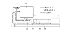
図2を参照すると、尿素水供給システムが模式的に示されている。図2中、尿素水供給配管22が実線で、冷却水配管40が破線で示されている。同図にように、尿素水供給システムは旋回フレーム3に配設されており、尿素水供給配管22は、油圧ショベルの作動時に尿素水が尿素水供給装置30により尿素水タンク24から吸い上げられて尿素水噴射弁20に圧送されるとともに、油圧ショベルの停止時には尿素水供給装置30により余剰の尿素水が尿素水供給装置30から尿素水タンク24に返戻されるよう構成されている。一方、冷却水配管40は、冷却水が、尿素水噴射弁20を回流するとともに、尿素水供給配管22に沿って尿素水供給装置30及び尿素水タンク24内を回流するよう構成されている。なお、冷却水配管40には、尿素水供給装置30の上流側に位置して冷却水圧送ポンプ42が介装されており、冷却水は冷却水圧送ポンプ42により圧送される。そして、尿素水供給配管22と冷却水配管40のうち尿素水供給装置30から尿素水タンク24までの部分及び冷却水が尿素水供給装置30からエンジン10に戻る部分とは、互いに接触するよう纏められており、冷却水の熱が良好に尿素水に伝達されて尿素水が保温されるよう保温材44によって覆われている。
These urea
Referring to FIG. 2, a urea water supply system is schematically shown. In FIG. 2, the urea
図3を参照すると、旋回フレーム3上に配設された本発明に係る尿素水供給システムが旋回フレーム3の平面図として示され、図4を参照すると、本発明に係る尿素水供給システムが図3のA−A線に沿う旋回フレーム3の縦断面図として示されている。
図3に示すように、旋回フレーム3は、左右方向に所定の間隔をもって幅方向中央を前後方向に延びて旋回体2を補強する一対のセンターフレーム3b、3bと、一対のセンターフレーム3b、3bを前部で連結する前部連結フレーム3c及び後部で連結する後部連結フレーム3dと、各センターフレーム3bから左右方向で外方に延びる複数の張出しビームの先端をそれぞれ前後方向に延びるサイドビームで繋いで形成される一対のサイドフレーム3e、3eと、これらのフレームに対して取り付けられる複数の底板3aとにより概略構成されている。
このような旋回フレーム3において、作業装置4がセンターフレーム3bの前部に連結され、エンジン10は、旋回フレーム3の中心より後部側にてブラケット3fを介してセンターフレーム3b、3bより後方に延びるテールフレーム部3b’、3b’に載置されている。なお、底板3aのうちエンジン10の真下の下方部分には、作業者がエンジン10のメンテナンス(整備)を行うため、メンテナンス作業用に開口部3gが設けられている。
Referring to FIG. 3, the urea water supply system according to the present invention disposed on the swivel frame 3 is shown as a plan view of the swivel frame 3. Referring to FIG. 4, the urea water supply system according to the present invention is illustrated. 3 is shown as a longitudinal sectional view of the swivel frame 3 taken along line AA.
As shown in FIG. 3, the revolving frame 3 includes a pair of
In such a turning frame 3, the working device 4 is connected to the front part of the
尿素水タンク24は、尿素水の補給作業性が良いことから、またエンジン10の熱による尿素水の変質を防止すべく極力エンジン10から離れるよう、旋回フレーム3の前部のうちセンターフレーム3bを挟んで運転室8とは反対側のサイドフレーム3e上に配設されている。
尿素水供給装置30は、エンジン10の近傍であってエンジン10よりも旋回フレーム3の中心側に、エンジン10を臨むよう位置して配設されている。詳しくは、図3及び図4に示すように、後部連結フレーム3dは、一対のセンターフレーム3b、3b間に底板3aに対し垂直となるよう渡された既存のプレート部材であって、エンジン10を後部側に臨むようにエンジン10より前側の下方に位置して配設されており、尿素水供給装置30は、後部連結フレーム3dのエンジン10側の面にエンジン10を臨むようにエンジン10に対面して配設されている。
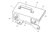
図5を参照すると、尿素水供給装置30を斜め上方から見た斜視図が示されており、以下、尿素水供給装置30の構成について説明する。
The
The urea
Referring to FIG. 5, a perspective view of the urea
同図に示すように、尿素水供給装置30は後部連結フレーム3dに固定されており、尿素水供給装置30には、上述したように尿素水供給配管22と冷却水配管40とが接続されている。また、尿素水供給装置30には、尿素水供給装置30の上部を覆うようにして保温カバー50が取り付けられている。
詳しくは、尿素水供給装置30は台座部材36を介して複数のボルト36aによって後部連結フレーム3dに固定されており、台座部材36は、保温カバー50を取り付けるための腕部材37、38、39を一体または別体に含んで構成されており、保温カバー50は、腕部材37、38、39にボルト51で締結されることで、台座部材36ひいては尿素水供給装置30に固定されている。
As shown in the figure, the urea
Specifically, the urea
図6を参照すると、保温カバー50を外した状態の尿素水供給装置30が示されている。同図に示すように、尿素水供給配管22と冷却水配管40と尿素水供給装置30とはそれぞれコネクタを介して接続されている。詳しくは、尿素水供給配管22のうち尿素水タンク24から尿素水が流入する流入配管はコネクタ31で、尿素水タンク24へ尿素水を返戻する流出配管はコネクタ32で、尿素水噴射弁20へ尿素水を給送する流出配管はコネクタ33で尿素水供給装置30に接続されている。また、冷却水配管40のうちエンジン10から冷却水が流入する流入配管はコネクタ34で、尿素水タンク24へ冷却水を給送する流出配管はコネクタ35で尿素水供給装置30に接続されている。
Referring to FIG. 6, the urea
また、これらコネクタ31、32、33、34、35は、全て尿素水供給装置30の同一の外面、即ち後部連結フレーム3dの面に対し垂直をなす上面30aに垂直に接続されている。そして、尿素水供給配管22のコネクタ31、32、33及び冷却水配管40のコネクタ34、35は、コネクタ34、35が後部連結フレーム3d側となるようにして、それぞれ後部連結フレーム3dに対し平行且つ互いに平行に車体左右方向に一直線状に並ぶように配設されている。
同図に示すように、冷却水配管40のうち冷却水圧送ポンプ42を経てエンジン10からの冷却水が流入する流入配管における尿素水供給装置30上に延長し迂回して配索される一部分(コネクタ34に向かう部分)は、尿素水供給配管22のコネクタ31、32、33に対して所定の距離範囲で接近するように配設されている。即ち、尿素水供給配管22の端部における尿素水供給装置30への接続部(コネクタ31、32、33部分)近傍では、冷却水配管40を沿わせ束ねることができず、尿素水の凍結を防止したり凍結した尿素水を解凍したりすることが困難である。そのため、冷却水配管40のうちエンジン10からの冷却水が流入する流入配管の尿素水供給装置30上に延長して配索される一部分を加温配管部46とし、この加温配管部46をコネクタ31、32、33に接近させ、コネクタ31、32、33近傍部分を加温配管部46を流れる冷却水の熱で加温するようにしている。
These
As shown in the figure, a portion of the cooling
詳しくは、加温配管部46は、尿素水供給装置30の上面30aに沿って尿素水供給配管22のコネクタ31、32、33と冷却水配管40のコネクタ34、35との間を延び、上面30aに対し垂直をなすコネクタ31、32、33を横切るように配設されている。そして、加温配管部46はボルト47で上面30aに固定されている。
ここに、加温配管部46をコネクタ31、32、33に接近させる所定の距離範囲は、例えば加温配管部46を流れる冷却水の熱がコネクタ31、32、33に届く範囲である。また、加温配管部46がコネクタ31、32、33に接近する部分は、冷却水の熱がコネクタ31、32、33に届き易いよう、熱伝導性の大きな部材、例えば銅管や鋼管等の金属部材で構成されている。
Specifically, the
Here, the predetermined distance range in which the
この際、図6に示すように、コネクタ31、32から延びる尿素水供給配管22は上面30aに対し平行に延びており、加温配管部46は、コネクタ31、32、33に接近することで、コネクタ31、32から延びる尿素水供給配管22をも横切ることとなる。つまり、加温配管部46は、コネクタ31、32近傍の冷却水配管40を沿わせられない尿素水供給配管22の部分にも接近するように配設されている。これにより、コネクタ31、32、33のみならず、コネクタ31、32から延びる尿素水供給配管22の部分についても加温配管部46を流れる冷却水の熱で同時に加温可能である。
なお、放熱性を高めるべく加温配管部46にフィンを設けることも考えられるが、フィンを設けると却って加温配管部46をコネクタ31、32、33に接近させることができなくなるため、加温配管部46にはフィンを設けないのが好ましい。
At this time, as shown in FIG. 6, the urea
Although it is conceivable to provide fins in the
また、同図に示すように、台座部材36に設けられた腕部材37、38、39には、それぞれ保温カバー50を取り付けるボルト51を螺合させるためのボルト螺合孔37a、38a、39aが形成されている。
さらに、後部連結フレーム3dの尿素水供給装置30側の面には、下部を後部連結フレーム3dと台座部材36とで挟むようにして、保温部材48が設けられている。保温部材48は、例えばウレタン部材等で構成される。
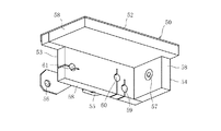
図7及び図8を参照すると、尿素水供給装置30から外した状態の保温カバー50の表側と裏側とがそれぞれ斜視図で示されている。保温カバー50は、例えば鋼板を加工して、上面52と後部連結フレーム3dに対し平行をなす第1側面53と後部連結フレーム3dに対し垂直をなす第2側面54とから構成されている。第1側面53には、保温カバー50を台座部材36に設けられた腕部材37、38に取り付けるべくボルト51を貫通させるボルト貫通孔55、56が形成されており、第2側面54には保温カバー50を台座部材36に設けられた腕部材39に取り付けるべくボルト51を貫通させるボルト貫通孔57が形成されている。
Also, as shown in the figure, the
Further, a
Referring to FIGS. 7 and 8, the front side and the back side of the
保温カバー50の裏側、即ち上面52、第1側面53及び第2側面54の尿素水供給装置30側の面には、図8に示すように、保温部材58が設けられている。保温部材58は、上記保温部材48と同様、例えばウレタン部材等で構成され、保温部材48と略同一の厚みを有している。
保温カバー50の第1側面53には、上記尿素水供給配管22や冷却水配管40との干渉を避けるために切欠部53a、53bが設けられており、保温部材58は、尿素水供給配管22や冷却水配管40を通すための貫通孔59、60、61を残して、これら切欠部53a、53bを塞ぐように設けられている。
As shown in FIG. 8, a
The
そして、上記保温部材48と保温部材58とは、保温カバー50を尿素水供給装置30に取り付けたとき、上面52に配した保温部材58が保温部材48の上端縁と当接し、第2側面54に配した保温部材58の側端縁が保温部材48の表面と当接するように構成されている。即ち、保温カバー50は、尿素水供給装置30に取り付けることで、開口した第1側面53に対向する後部連結フレーム3d側の面が後部連結フレーム3dの表面に配された保温部材48ひいては後部連結フレーム3dで塞がれるよう構成されている。なお、第2側面54と対向する面は開口したままとなるが、この面は尿素水供給配管22や冷却水配管40の保温材44によって略閉じられた状態となる。これにより、尿素水供給配管22のコネクタ31、32、33と冷却水配管40のコネクタ34、35とが加温配管部46とともに保温カバー50によって塞がれ、保温カバー50の内部には上面52、第1側面53、第2側面54及び後部連結フレーム3dさらには保温材44で略囲まれた閉空間が形成される。故に、この閉空間内の空気は、加温配管部46を流れる冷却水の熱で加温され、保温部材48及び保温部材58の作用により良好に保温される。
When the
符号62は保温カバー50の取手であり、この取手62は、保温カバー50の着脱のみならず、保温カバー50を台座部材36を介して尿素水供給装置30に取り付けた状態であっても保温カバー50、台座部材36及び尿素水供給装置30を一体として運搬可能なように、その強度が設定されている。
ところで、冷却水配管40の尿素水供給配管22のコネクタ31、32、33への接近のさせ方は、上記に限られず、図9〜図11に示すように種々変形例が考えられる。
図9は第1変形例を示す。この第1変形例では、冷却水配管40のうちエンジン10からの冷却水の流入する流入配管の尿素水供給装置30上に延長して配索される一部分を加温配管部146としている。加温配管部146は、冷却水配管40のコネクタ34、35とは反対側で尿素水供給配管22のコネクタ31、32、33を横切るように配設されている。
By the way, how to approach the
FIG. 9 shows a first modification. In the first modification, a part of the cooling
図10は第2変形例を示す。この第2変形例では、冷却水配管40のうちエンジン10からの冷却水の流入する流入配管の尿素水供給装置30上に延長して配索される一部分を加温配管部246としている。加温配管部246は、尿素水供給配管22のコネクタ31、32、33と冷却水配管40のコネクタ34、35との間を延びてコネクタ31、32、33を横切るとともに、直列にして冷却水配管40のコネクタ34、35とは反対側でもコネクタ31、32、33を横切るように配設されている。即ち、加温配管部246は、直列にしてコネクタ31、32、33を取り囲むように配設されている。
図11は第3変形例を示す。この第3変形例では、冷却水配管40のうちエンジン10からの冷却水の流入する流入配管の尿素水供給装置30上に延長して配索される一部分を加温配管部346としている。加温配管部346は、尿素水供給配管22のコネクタ31、32、33と冷却水配管40のコネクタ34、35との間を延びてコネクタ31、32、33を横切るとともに、並列にして冷却水配管40のコネクタ34、35とは反対側でもコネクタ31、32、33を横切るように配設されている。即ち、加温配管部346は、並列にしてコネクタ31、32、33を取り囲むように配設されている。
FIG. 10 shows a second modification. In the second modification, a part of the cooling
FIG. 11 shows a third modification. In the third modification, a part of the cooling
以下、このように構成された建設機械の尿素水供給システムの作用及び効果について詳しく説明する。
上述したように、尿素水タンク24は、旋回フレーム3の前部のサイドフレーム3e上に配設されている一方、尿素水供給装置30は、エンジン10の近傍であって後部連結フレーム3dのエンジン10側の面にエンジン10を臨むように配設されている。
これより、尿素水タンク24はエンジン10の熱の影響を受けない一方、尿素水供給装置30はエンジン10の熱で加温され、冬季であっても尿素水供給装置30内を流れる尿素水の凍結が防止されるとともに凍結した尿素水の解凍が促進される。
Hereinafter, the operation and effect of the urea water supply system of the construction machine configured as described above will be described in detail.
As described above, the
Thus, while the
また、ここでは、尿素水供給装置30を後部連結フレーム3dのエンジン10側の面にエンジン10を臨むように配設しているので、別途取付ブラケットを設けることなく、プレート部材である既存の後部連結フレーム3dを有効に利用して尿素水供給装置30を容易にして好適に配設することができる。この場合、旋回フレーム3の底板3aのうち、エンジン10の真下の部分にはエンジン10等のメンテナンス作業用に開口部3gが設けられているので、この開口部3gを利用して尿素水供給装置30のメンテナンス作業を容易に行うことができる。
Here, since the urea
そして、このように尿素水供給装置30が後部連結フレーム3dのエンジン10側の面にエンジン10を臨むように配設されていると、尿素水タンク24から尿素水供給装置30までの距離が遠くなり過ぎることがなく、尿素水供給装置30から尿素水噴射弁20までの距離も遠くなり過ぎることがない。これにより、図12に旋回フレーム3と尿素水供給システムとを側方から見た図を模式的に示すが、このように建設機械が平地での状態(一点鎖線)から傾斜地等において前後方向で前方を下げて所定の傾斜限界角度θまで傾斜した場合(実線)であっても、尿素水タンク24から尿素水供給装置30までの垂直方向の距離の変化が小さく抑えられる。つまり、平地において尿素水タンク24の尿素水の吸い込み位置が尿素水供給装置30と垂直方向で略同一高さであるとすると、図12において、傾斜地等でのその垂直方向の変化量は尿素水供給装置30が尿素水タンク24から尿素水を吸い上げるのに支障がない規定値範囲内のΔH1となり、尿素水供給装置30の尿素水タンク24からの尿素水の吸い上げ性が変動少なく良好に確保される。
When the urea
同様に、尿素水供給装置30から尿素水噴射弁20までの垂直方向の距離の変化も小さく抑えられる。つまり、平地における尿素水供給装置30から尿素水噴射弁20までの距離がH2で、所定の傾斜限界角度θまで傾斜したときの距離がH2'とすると、図12において、その垂直方向の変化量は尿素水噴射弁20での尿素水の吐出圧に支障が出ない規定値範囲内のΔH2(ΔH2=H2'−H2)となり、尿素水噴射弁20に対する尿素水供給装置30の尿素水の吐出圧も変動少なく良好に確保される。
これにより、尿素水噴射弁20から常に安定して尿素水を噴射可能である。
Similarly, a change in the distance in the vertical direction from the urea
Thereby, urea water can be always stably injected from the urea
また、尿素水供給装置30において、冷却水配管40のうちエンジン10からの冷却水の流入する流入配管の尿素水供給装置30上に延長して配索される一部分を加温配管部46、146、246、346とし、この加温配管部46、146、246、346を尿素水供給配管22の尿素水供給装置30への接続部であるコネクタ31、32、33に接近させ、コネクタ31、32、33部分を加温配管部46を流れる冷却水の熱で加温するようにしているので、冷却水配管40を沿わせることができないようなコネクタ31、32、33部分においても、簡単な構成にして効率よく尿素水の凍結を防止したり凍結した尿素水を解凍したりすることが可能である。
Further, in the urea
この場合、上記第2変形例や第3変形例のように、加温配管部246、346をコネクタ31、32、33を取り囲むように構成すると、コネクタ31、32、33部分を加温配管部246、346を流れる冷却水の熱で十分に加温するようにできる。
特に、油圧ショベルの停止時には尿素水は尿素水供給装置30から尿素水タンク24に返戻されることになるが、この際、尿素水供給装置30から尿素水タンク24までの間の尿素水供給配管22内には尿素水が残ることがあり、尿素水タンク24へ尿素水を返戻する流出配管の接続部であるコネクタ32部分にも尿素水が残ることがあるが、加温配管部46を流れる冷却水の熱で加温することで、確実にコネクタ32部分での尿素水の凍結を防止したり凍結した尿素水を解凍したりすることが可能である。
In this case, if the
In particular, when the excavator is stopped, the urea water is returned from the urea
さらに、尿素水供給装置30には、尿素水供給配管22のコネクタ31、32、33と冷却水配管40のコネクタ34、35と加温配管部46とを覆うように保温カバー50を設けており、これにより保温カバー50の内部の加温配管部46を流れる冷却水の熱で加温された空気が良好に保温されるが、ここでは、保温カバー50を内面に保温部材58を配した上面52、第1側面53及び第2側面54で構成し、開口した第1側面53に対向する後部連結フレーム3d側の面については表面に保温部材48を配した後部連結フレーム3dで塞ぐようにして保温カバー50内に閉空間を形成するようにしているので、プレート部材からなる既存の後部連結フレーム3dを効率よく利用して保温カバー50を簡素に構成することができる。
そして、保温カバー50がこのように構成されていると、図4には併せて作業者Mを示すが、作業者Mがメンテナンス作業用の開口部3gから尿素水供給装置30の保温カバー50を容易に着脱可能であり、尿素水供給装置30のメンテナンス作業をより一層容易に行うことができる。
Further, the urea
When the
以上で実施形態の説明を終えるが、本発明の態様は上記実施形態に限定されるものではない。
例えば、上記実施形態では、冷却水配管40のうちエンジン10からの冷却水の流入する流入配管の尿素水供給装置30上に延長して配索される一部分(コネクタ34に向かう部分)を加温配管部46、146、246、346としたが、冷却水配管40のうちエンジン10からの冷却水の流出する流出配管の尿素水供給装置30上に延長して配索される一部分(コネクタ35から延びる部分)で加温配管部を構成するようにしてもよい。
また、上記実施形態では、尿素水供給装置30において、冷却水配管40の一部分で加温配管部46、146、246、346を構成し、この加温配管部46、146、246、346を尿素水供給配管22の尿素水供給装置30への接続部であるコネクタ31、32、33に接近させるようにしたが、尿素水タンク24に尿素水供給配管22の尿素水タンク24への接続部としてのコネクタと冷却水配管40の尿素水タンク24への接続部としてのコネクタとが設けられている場合には、尿素水タンク24において、冷却水配管40のうちエンジン10からの冷却水の流入する流入配管の一部分或いは流出する流出配管の一部分を加温配管部とし、この加温配管部を尿素水供給配管22の尿素水タンク24への接続部であるコネクタに接近させるようにしてもよい。
The description of the embodiment is finished as above, but the aspect of the present invention is not limited to the above embodiment.
For example, in the above-described embodiment, a part of the cooling
In the above-described embodiment, in the urea
また、上記実施形態では、尿素水供給装置30において、冷却水配管40を延長して加温配管部46、146、246、346を構成し、加温配管部46、146、246、346を含めて尿素水供給配管22の尿素水供給装置30への接続部であるコネクタ31、32、33と冷却水配管40のコネクタ34、35とを保温カバー50で覆うようにしているが、尿素水供給装置30において加温配管部46、146、246、346を設けることなくコネクタ31、32、33、34、35を保温カバー50で覆うようにしてもよい。この場合、冷却水配管40を通すための貫通孔60、61については保温部材58に設ける必要はない。
In the above embodiment, in the urea
また、上記実施形態では、建設機械としてクローラ式の油圧ショベルを例に挙げて説明したが、これに限られるものではなく、エンジンが尿素SCRシステムを備えていれば、本発明を、ホイール式の油圧ショベルに適用してもよいし、リフトトラック、ダンプトラック、ホイールローダ、油圧クレーン、ブルドーザ等の建設機械の他、走行体を有さない港湾や船舶上で使用される油圧ショベルにも広く適用することが可能である。 In the above embodiment, the crawler type hydraulic excavator has been described as an example of the construction machine. However, the present invention is not limited to this, and the present invention is not limited to the wheel type as long as the engine includes the urea SCR system. It can be applied to hydraulic excavators, and it can also be widely applied to construction machines such as lift trucks, dump trucks, wheel loaders, hydraulic cranes, bulldozers, etc. Is possible.
1 走行体
2 旋回体
3 旋回フレーム
3b センターフレーム
3d 後部連結フレーム
4 作業装置
9 機械室
10 エンジン
11 排気後処理装置
20 尿素水噴射弁
22 尿素水供給配管
24 尿素水タンク
30 尿素水供給装置
31、32、33、34、35 コネクタ
40 冷却水配管
46、146、246、346 加温配管部
48 保温部材
50 保温カバー
58 保温部材
DESCRIPTION OF SYMBOLS 1 Traveling body 2 Swing body 3
Claims (2)
前記エンジンの排気通路に介装されたNOx選択還元触媒装置と、
前記NOx選択還元触媒の排気上流に尿素水を噴射する尿素水噴射弁と、
前記尿素水を貯蔵する尿素水タンクと、
一端が前記尿素水噴射弁に接続され、他端が前記尿素水タンクに接続された尿素水供給配管と、
前記尿素水供給配管に介装され、尿素水を前記尿素水噴射弁に圧送する尿素水供給装置と、
前記尿素水供給配管に沿って延び、前記エンジンの冷却水を流通させる冷却水配管と、
を備え、
前記冷却水配管は、
流入配管と流出配管とからなり、
前記流入配管と前記流出配管とが前記尿素水タンク及び前記尿素水供給装置のうち少なくともいずれか一方に接続され、
前記尿素水供給配管の前記尿素水タンクとの接続部及び前記尿素水供給装置との接続部のうち少なくともいずれか一方に関し、前記流入配管の一部分及び前記流出配管の一部分のうちいずれか一方が前記接続部に対し接近して配設され、
前記冷却水配管が前記接続部に接近して配設されてなる前記尿素水タンク及び前記尿素水供給装置では、前記尿素水供給配管は、全て前記尿素水タンク及び前記尿素水供給装置の同一の外面に垂直に接続されて前記接続部をなしており、
前記冷却水配管の前記流入配管の一部分及び前記流出配管の一部分のうちいずれか一方は、前記外面に沿い延びて前記接続部を横切るとともに、前記接続部を取り囲むように配設されてなる、建設機械の尿素水供給システム。 An engine as a drive source placed on the revolving structure;
A NOx selective reduction catalyst device interposed in the exhaust passage of the engine;
A urea water injection valve that injects urea water upstream of the exhaust of the NOx selective reduction catalyst;
A urea water tank for storing the urea water;
A urea water supply pipe having one end connected to the urea water injection valve and the other end connected to the urea water tank;
A urea water supply device that is interposed in the urea water supply pipe and pressure-feeds the urea water to the urea water injection valve;
A cooling water pipe that extends along the urea water supply pipe and distributes the cooling water of the engine;
With
The cooling water pipe is
It consists of inflow piping and outflow piping,
It said inlet pipe and said outlet pipe is connected to at least one of the urea water tank and the urea water supply device,
Relates to at least one of the connecting portion between the connecting portion and the urea water supply device of the urea water tank of the urea water supply pipe, one said of a portion of the inlet pipe of a portion and the outlet pipe Arranged close to the connection ,
In the urea water tank and the urea water supply device in which the cooling water piping is disposed close to the connection portion, the urea water supply piping is all the same as the urea water tank and the urea water supply device. Connected vertically to the outer surface to form the connecting portion,
One of the inlet pipe and the outlet pipe of the cooling water pipe extends along the outer surface, crosses the connection portion, and is disposed so as to surround the connection portion. Mechanical urea water supply system.
Priority Applications (5)
| Application Number | Priority Date | Filing Date | Title |
|---|---|---|---|
| JP2014054000A JP6088458B2 (en) | 2014-03-17 | 2014-03-17 | Urea water supply system for construction machinery |
| PCT/JP2015/054628 WO2015141374A1 (en) | 2014-03-17 | 2015-02-19 | Aqueous urea supply system for construction machine |
| CN201580001939.2A CN105556079B (en) | 2014-03-17 | 2015-02-19 | The urea water supply system of engineering machinery |
| US15/022,933 US10066531B2 (en) | 2014-03-17 | 2015-02-19 | Urea water supply system for construction machine |
| EP15765284.3A EP3121400B1 (en) | 2014-03-17 | 2015-02-19 | Urea water supply system for construction machine |
Applications Claiming Priority (1)
| Application Number | Priority Date | Filing Date | Title |
|---|---|---|---|
| JP2014054000A JP6088458B2 (en) | 2014-03-17 | 2014-03-17 | Urea water supply system for construction machinery |
Publications (3)
| Publication Number | Publication Date |
|---|---|
| JP2015175333A JP2015175333A (en) | 2015-10-05 |
| JP2015175333A5 JP2015175333A5 (en) | 2015-11-12 |
| JP6088458B2 true JP6088458B2 (en) | 2017-03-01 |
Family
ID=54144353
Family Applications (1)
| Application Number | Title | Priority Date | Filing Date |
|---|---|---|---|
| JP2014054000A Active JP6088458B2 (en) | 2014-03-17 | 2014-03-17 | Urea water supply system for construction machinery |
Country Status (5)
| Country | Link |
|---|---|
| US (1) | US10066531B2 (en) |
| EP (1) | EP3121400B1 (en) |
| JP (1) | JP6088458B2 (en) |
| CN (1) | CN105556079B (en) |
| WO (1) | WO2015141374A1 (en) |
Families Citing this family (6)
| Publication number | Priority date | Publication date | Assignee | Title |
|---|---|---|---|---|
| WO2016079773A1 (en) * | 2014-11-21 | 2016-05-26 | 株式会社Kcm | Industrial vehicle |
| CN105386832B (en) * | 2015-12-23 | 2017-09-05 | 安徽江淮汽车集团股份有限公司 | Cool down water distribution valves and engine assembly |
| JP6495196B2 (en) * | 2016-03-15 | 2019-04-03 | 日立建機株式会社 | Construction machinery |
| CN106523094A (en) * | 2016-12-29 | 2017-03-22 | 雷沃重工股份有限公司 | Control device for adjusting SCR temperature and agricultural machinery |
| JP6719425B2 (en) * | 2017-07-05 | 2020-07-08 | ヤンマーパワーテクノロジー株式会社 | Urea water supply device |
| JP6934439B2 (en) * | 2018-03-19 | 2021-09-15 | 日立建機株式会社 | Construction machinery |
Family Cites Families (13)
| Publication number | Priority date | Publication date | Assignee | Title |
|---|---|---|---|---|
| CA2199737C (en) * | 1994-09-13 | 2000-04-11 | Lothar Hofman | Method and device for introducing a fluid into an exhaust-gas purificat ion system |
| JP3751962B2 (en) * | 2003-09-05 | 2006-03-08 | 日産ディーゼル工業株式会社 | Engine exhaust purification system |
| EP2253814B1 (en) * | 2006-07-12 | 2011-11-02 | Delphi Technologies Holding S.à.r.l. | Insulated reagent dosing device |
| JPWO2009001587A1 (en) * | 2007-06-26 | 2010-08-26 | 日立建機株式会社 | Self-propelled construction machinery |
| JP5020878B2 (en) | 2008-03-28 | 2012-09-05 | 興国インテック株式会社 | Exhaust gas purification reducing agent thawing heat retention device |
| JP2010132194A (en) * | 2008-12-05 | 2010-06-17 | Mitsubishi Fuso Truck & Bus Corp | Rear engine bus |
| US20110030349A1 (en) | 2009-08-04 | 2011-02-10 | International Engine Intellectual Property Company, Llc | Quick-heating of a urea supply conduit for an engine exhaust after-treatment system |
| JP5533234B2 (en) * | 2010-05-17 | 2014-06-25 | いすゞ自動車株式会社 | Urea water tank structure |
| DE102010061222B4 (en) * | 2010-12-14 | 2015-05-07 | Cummins Ltd. | SCR exhaust treatment device |
| JP5631803B2 (en) * | 2011-04-21 | 2014-11-26 | 日立建機株式会社 | Construction machinery |
| JP5640939B2 (en) * | 2011-09-20 | 2014-12-17 | 三菱ふそうトラック・バス株式会社 | Piping support structure for urea water tank |
| US20130145749A1 (en) * | 2011-12-12 | 2013-06-13 | Caterpillar Inc. | Fluid manifold for use in an scr dosing system |
| US9381466B2 (en) | 2012-04-03 | 2016-07-05 | Korea Institute Of Machinery & Materials | Exhaust gas purification system |
-
2014
- 2014-03-17 JP JP2014054000A patent/JP6088458B2/en active Active
-
2015
- 2015-02-19 WO PCT/JP2015/054628 patent/WO2015141374A1/en active Application Filing
- 2015-02-19 EP EP15765284.3A patent/EP3121400B1/en active Active
- 2015-02-19 CN CN201580001939.2A patent/CN105556079B/en active Active
- 2015-02-19 US US15/022,933 patent/US10066531B2/en active Active
Also Published As
| Publication number | Publication date |
|---|---|
| CN105556079A (en) | 2016-05-04 |
| JP2015175333A (en) | 2015-10-05 |
| EP3121400A4 (en) | 2017-09-06 |
| WO2015141374A1 (en) | 2015-09-24 |
| US20160230633A1 (en) | 2016-08-11 |
| EP3121400B1 (en) | 2018-09-12 |
| US10066531B2 (en) | 2018-09-04 |
| CN105556079B (en) | 2018-04-27 |
| EP3121400A1 (en) | 2017-01-25 |
Similar Documents
| Publication | Publication Date | Title |
|---|---|---|
| JP6088458B2 (en) | Urea water supply system for construction machinery | |
| JP5940107B2 (en) | Urea water supply system for construction machinery | |
| US9003779B2 (en) | Wheel loader | |
| KR102057634B1 (en) | Construction machinery | |
| US9194104B2 (en) | Wheel loader | |
| JP5501537B1 (en) | Reducing agent tank and work vehicle | |
| JP2012237232A (en) | Construction machine | |
| KR20100033482A (en) | Self-propelled construction machine | |
| JP6445476B2 (en) | Construction machinery | |
| JP5723493B1 (en) | Excavator | |
| JP6071855B2 (en) | Construction machinery | |
| JP5468393B2 (en) | Construction machinery | |
| JP2016102362A (en) | Construction machine | |
| JP2009068395A (en) | Exhaust gas after-treatment device for working machine | |
| JP6480234B2 (en) | Work machine | |
| JP6338141B2 (en) | Construction machinery | |
| JP6158729B2 (en) | Construction machinery | |
| JP4855492B2 (en) | Construction machinery | |
| JP4855491B2 (en) | Construction machinery | |
| JP6391523B2 (en) | Working machine | |
| JP2020133557A (en) | Construction machine | |
| JP2018003539A (en) | Construction machine |
Legal Events
| Date | Code | Title | Description |
|---|---|---|---|
| A521 | Request for written amendment filed |
Free format text: JAPANESE INTERMEDIATE CODE: A523 Effective date: 20150911 |
|
| A621 | Written request for application examination |
Free format text: JAPANESE INTERMEDIATE CODE: A621 Effective date: 20150911 |
|
| A131 | Notification of reasons for refusal |
Free format text: JAPANESE INTERMEDIATE CODE: A131 Effective date: 20160727 |
|
| A521 | Request for written amendment filed |
Free format text: JAPANESE INTERMEDIATE CODE: A523 Effective date: 20160923 |
|
| TRDD | Decision of grant or rejection written | ||
| A01 | Written decision to grant a patent or to grant a registration (utility model) |
Free format text: JAPANESE INTERMEDIATE CODE: A01 Effective date: 20170125 |
|
| A61 | First payment of annual fees (during grant procedure) |
Free format text: JAPANESE INTERMEDIATE CODE: A61 Effective date: 20170203 |
|
| R150 | Certificate of patent or registration of utility model |
Ref document number: 6088458 Country of ref document: JP Free format text: JAPANESE INTERMEDIATE CODE: R150 |