WO2019172155A1 - 搬送装置(transport device) - Google Patents
搬送装置(transport device) Download PDFInfo
- Publication number
- WO2019172155A1 WO2019172155A1 PCT/JP2019/008274 JP2019008274W WO2019172155A1 WO 2019172155 A1 WO2019172155 A1 WO 2019172155A1 JP 2019008274 W JP2019008274 W JP 2019008274W WO 2019172155 A1 WO2019172155 A1 WO 2019172155A1
- Authority
- WO
- WIPO (PCT)
- Prior art keywords
- holding
- article
- unit
- pair
- arrangement direction
- Prior art date
- Legal status (The legal status is an assumption and is not a legal conclusion. Google has not performed a legal analysis and makes no representation as to the accuracy of the status listed.)
- Ceased
Links
Images



Classifications
-
- H—ELECTRICITY
- H10—SEMICONDUCTOR DEVICES; ELECTRIC SOLID-STATE DEVICES NOT OTHERWISE PROVIDED FOR
- H10P—GENERIC PROCESSES OR APPARATUS FOR THE MANUFACTURE OR TREATMENT OF DEVICES COVERED BY CLASS H10
- H10P72/00—Handling or holding of wafers, substrates or devices during manufacture or treatment thereof
- H10P72/30—Handling or holding of wafers, substrates or devices during manufacture or treatment thereof for conveying, e.g. between different workstations
- H10P72/32—Handling or holding of wafers, substrates or devices during manufacture or treatment thereof for conveying, e.g. between different workstations between different workstations
- H10P72/3214—Handling or holding of wafers, substrates or devices during manufacture or treatment thereof for conveying, e.g. between different workstations between different workstations by means of a cart or a vehicle
-
- B—PERFORMING OPERATIONS; TRANSPORTING
- B65—CONVEYING; PACKING; STORING; HANDLING THIN OR FILAMENTARY MATERIAL
- B65G—TRANSPORT OR STORAGE DEVICES, e.g. CONVEYORS FOR LOADING OR TIPPING, SHOP CONVEYOR SYSTEMS OR PNEUMATIC TUBE CONVEYORS
- B65G1/00—Storing articles, individually or in orderly arrangement, in warehouses or magazines
- B65G1/02—Storage devices
- B65G1/04—Storage devices mechanical
-
- B—PERFORMING OPERATIONS; TRANSPORTING
- B65—CONVEYING; PACKING; STORING; HANDLING THIN OR FILAMENTARY MATERIAL
- B65G—TRANSPORT OR STORAGE DEVICES, e.g. CONVEYORS FOR LOADING OR TIPPING, SHOP CONVEYOR SYSTEMS OR PNEUMATIC TUBE CONVEYORS
- B65G1/00—Storing articles, individually or in orderly arrangement, in warehouses or magazines
- B65G1/02—Storage devices
- B65G1/04—Storage devices mechanical
- B65G1/0457—Storage devices mechanical with suspended load carriers
-
- B—PERFORMING OPERATIONS; TRANSPORTING
- B66—HOISTING; LIFTING; HAULING
- B66C—CRANES; LOAD-ENGAGING ELEMENTS OR DEVICES FOR CRANES, CAPSTANS, WINCHES, OR TACKLES
- B66C13/00—Other constructional features or details
- B66C13/04—Auxiliary devices for controlling movements of suspended loads, or preventing cable slack
- B66C13/06—Auxiliary devices for controlling movements of suspended loads, or preventing cable slack for minimising or preventing longitudinal or transverse swinging of loads
-
- H—ELECTRICITY
- H10—SEMICONDUCTOR DEVICES; ELECTRIC SOLID-STATE DEVICES NOT OTHERWISE PROVIDED FOR
- H10P—GENERIC PROCESSES OR APPARATUS FOR THE MANUFACTURE OR TREATMENT OF DEVICES COVERED BY CLASS H10
- H10P72/00—Handling or holding of wafers, substrates or devices during manufacture or treatment thereof
- H10P72/30—Handling or holding of wafers, substrates or devices during manufacture or treatment thereof for conveying, e.g. between different workstations
- H10P72/32—Handling or holding of wafers, substrates or devices during manufacture or treatment thereof for conveying, e.g. between different workstations between different workstations
- H10P72/3202—Mechanical details, e.g. rollers or belts
-
- H—ELECTRICITY
- H10—SEMICONDUCTOR DEVICES; ELECTRIC SOLID-STATE DEVICES NOT OTHERWISE PROVIDED FOR
- H10P—GENERIC PROCESSES OR APPARATUS FOR THE MANUFACTURE OR TREATMENT OF DEVICES COVERED BY CLASS H10
- H10P72/00—Handling or holding of wafers, substrates or devices during manufacture or treatment thereof
- H10P72/30—Handling or holding of wafers, substrates or devices during manufacture or treatment thereof for conveying, e.g. between different workstations
- H10P72/32—Handling or holding of wafers, substrates or devices during manufacture or treatment thereof for conveying, e.g. between different workstations between different workstations
- H10P72/3218—Conveying cassettes, containers or carriers
-
- H—ELECTRICITY
- H10—SEMICONDUCTOR DEVICES; ELECTRIC SOLID-STATE DEVICES NOT OTHERWISE PROVIDED FOR
- H10P—GENERIC PROCESSES OR APPARATUS FOR THE MANUFACTURE OR TREATMENT OF DEVICES COVERED BY CLASS H10
- H10P72/00—Handling or holding of wafers, substrates or devices during manufacture or treatment thereof
- H10P72/30—Handling or holding of wafers, substrates or devices during manufacture or treatment thereof for conveying, e.g. between different workstations
- H10P72/32—Handling or holding of wafers, substrates or devices during manufacture or treatment thereof for conveying, e.g. between different workstations between different workstations
- H10P72/3221—Overhead conveying
-
- B—PERFORMING OPERATIONS; TRANSPORTING
- B65—CONVEYING; PACKING; STORING; HANDLING THIN OR FILAMENTARY MATERIAL
- B65G—TRANSPORT OR STORAGE DEVICES, e.g. CONVEYORS FOR LOADING OR TIPPING, SHOP CONVEYOR SYSTEMS OR PNEUMATIC TUBE CONVEYORS
- B65G2201/00—Indexing codes relating to handling devices, e.g. conveyors, characterised by the type of product or load being conveyed or handled
- B65G2201/02—Articles
- B65G2201/0297—Wafer cassette
Definitions
- the present invention relates to a traveling unit that travels along a rail, a holding unit that is connected to the traveling unit and holds an article, and a turn that turns the article held by the holding unit around a vertical axis along the vertical direction. And a conveyance device including the unit.
- Patent Document 1 Japanese Patent Laid-Open No. 2016-172607
- the transport device of Patent Document 1 includes a traveling unit (22) that travels along a rail, a holding unit (supporting mechanism 24) that is connected to the traveling unit (22) and holds an article, and a holding unit that is around the vertical axis. And a revolving part (rotating operation mechanism 27) for revolving.
- the holding article is swung around the vertical axis so that the holding article, which is the article held by the holding section, has a posture corresponding to the conveyance target position by turning the holding section by the turning section. It is comprised so that it can be made to.
- the transport device includes a pair of regulating bodies (30) arranged along the alignment direction along the direction in which the traveling unit travels. Some are equipped with.
- the pair of regulating bodies (30) are arranged separately on both sides of the article held by the holding part (supporting mechanism 19) as viewed in the vertical direction, and the article held by the holding part (supporting mechanism 19) is Even in the case of shaking, the swing of the article is regulated by the article coming into contact with the regulating body (30).
- the article includes a held part that is held by a holding part, and there is an article in which the held part is arranged to be shifted from the center of the article in a plan view. Further, even when the held portion is disposed at the center of the article in plan view, there is an article in which the shape of the outer surface around the vertical axis is not regular.
- the position of the outer surface around the longitudinal axis of the article changes according to the turning angle around the longitudinal axis of the holding part by the turning part.
- the characteristic configuration of the transport device includes a traveling unit that travels along the rail, a holding unit that is connected to the traveling unit and holds an article, and the article that is held by the holding unit and the holding unit.
- a revolving part for turning a holding article around a vertical axis along the vertical direction, a pair of restriction bodies arranged separately on both sides of the holding article as viewed in the vertical direction, and a restriction body for moving the pair of restriction bodies An adjustment unit,
- the direction in which the pair of regulating bodies are arranged in the vertical direction is the arrangement direction
- one side of the arrangement direction is the arrangement direction first side
- the opposite side is the arrangement direction second side
- the pair of the restrictions in the arrangement direction With the center position of the body as the center position, the holding article faces the first side face facing the first side in the arrangement direction and the second side in the arrangement direction according to the turning angle of the holding part by the turning part.
- the second side surface has a shape that changes its position in the arrangement direction, and the first regulation body on the first side in the arrangement direction of the pair of regulation bodies is arranged to face the first side surface.
- the second restricting body on the second side in the arrangement direction of the pair of restricting bodies is disposed to face the second side surface, and the restricting body adjusting portion is in accordance with the posture of the holding article. The center position is adjusted.
- the regulating body adjusting unit adjusts the center position of the pair of regulating bodies according to the posture of the holding article, so that the pair of regulating bodies corresponds to the first side surface and the second side surface. Can be arranged. Therefore, the pair of regulating bodies can be arranged at appropriate positions regardless of the turning angle of the holding portion. Therefore, even when the article held by the holding unit is shaken, it is possible to appropriately regulate the swing of the article by the article coming into contact with the regulating body.
- FIG. 1st control position of a pair of control body, and the 1st holding position of a holding part The figure which shows the 2nd control position of a pair of control body, and the 2nd holding position of a holding
- the article transport facility includes a rail 1 installed near the ceiling, an article transport vehicle 2 corresponding to the transport apparatus, and a processing apparatus 3 that performs processing on the article 6.
- a support 4 for supporting the article 6 is provided at a position adjacent to the processing device 3.
- the article transport vehicle 2 travels along the rail 1 and transports the article 6.
- the article 6 before being processed by the processing apparatus 3 is transported from a transport source (not shown) to the support base 4, and the article 6 after being processed by the processing apparatus 3 is transported to the support base. 4 to a destination outside the figure.
- the article 6 is a container that can store a plurality of plate-shaped objects. More specifically, the article 6 according to this example is a container that accommodates a plurality of wafers with dicing frames attached thereto. As illustrated in FIG. 3, the article 6 includes a main body portion 7 that accommodates an article and a flange portion 8 that is attached to the upper surface of the main body portion 7. As shown in FIGS. 5 to 9, the main body 7 is formed with an opening 9 for taking in and out the contents.
- the direction in which the contents are taken in and out in the vertical direction Z is referred to as the depth direction D
- the direction orthogonal to the depth direction D in the vertical direction is referred to as the width direction W.
- the article 6 is formed in a square shape in which the shape in the vertical direction Z is the same in the width direction W and the depth direction D.
- the flange portion 8 is attached to the center of the main body portion 7 in the width direction W, and is attached to the front side (the side where the opening 9 is located with respect to the center) in the depth direction D from the center of the main body portion 7.
- the center position of the flange portion 8 as viewed in the vertical direction Z corresponds to the position of the vertical axis P ⁇ b> 1 serving as a turning axis when the turning operation portion 18 described later is turned.
- the vertical axis P1 (turning center) is located on the front side of the article center P3 located in the center of the article 6 in the depth direction D and in the center of the width direction W.
- the article 6 is transported to the support base 4 by the article transporting vehicle 2 in a posture in which the opening 9 faces the processing device 3.
- the article transport vehicle 2 As shown in FIGS. 1 to 3, the direction in which the traveling unit 11 travels is referred to as an alignment direction X, and the direction orthogonal to the alignment direction X as viewed in the vertical direction Z is referred to as a lateral width direction Y.
- One side of the arrangement direction X is referred to as an arrangement direction first side X1, and the opposite side is referred to as an arrangement direction second side X2.
- one side of the lateral width direction Y is referred to as a lateral width direction first side Y1, and the opposite side is referred to as a lateral width direction second side Y2.
- the article transport vehicle 2 includes a traveling unit 11 that travels on the rail 1 along the rail 1, a holding unit 12 that is connected to the traveling unit 11 and holds the article 6, and a traveling unit 11. And a storage portion 13 that forms a storage chamber 13 ⁇ / b> C that is connected and stores the article 6.
- the holding part 12 and the accommodating part 13 are connected to the traveling part 11 so as to be positioned below the rail 1.
- the traveling unit 11 includes a traveling wheel 11A that rolls on the rail 1 and a traveling motor 11B that rotationally drives the traveling wheel 11A.
- the traveling unit 11 is configured to travel along the rail 1 by rotationally driving the traveling wheel 11A by driving the traveling motor 11B.
- the holding portion 12 includes a pair of gripping claws 12A that can move toward and away from each other along the horizontal direction, and a gripping motor 12B (see FIG. 4) that moves the pair of gripping claws 12A toward and away from each other. Yes.
- the holding unit 12 moves the pair of gripping claws 12A toward and away from each other by driving the pair of gripping motors 12B, so that the pair of gripping claws 12A grips the flange portion 8 of the article 6 and the pair of gripping claws 12A. It is configured to switch to a state in which the gripping of the flange portion 8 by the gripping claws 12A is released.
- the holding portion 12 is configured to hold the flange portion 8 provided at the upper end portion of the article 6, specifically, the upper end portion of the article 6.
- the article 6 held by the holding unit 12 will be described as a holding article 6A.
- the accommodating portion 13 includes a first wall portion 13A located on the first side X1 in the arrangement direction with respect to the holding portion 12, and a second wall portion 13B located on the second side X2 in the arrangement direction with respect to the holding portion 12. I have. 13 A of 1st wall parts and the 2nd wall part 13B are provided in the state which overlaps by the alignment direction X view, and 13 C of storage chambers are formed between these 13 A of 1st wall parts and the 2nd wall part 13B. .
- the article transport vehicle 2 includes a lifting operation unit 16 that moves the holding unit 12 up and down relative to the traveling unit 11, and a sliding movement of the holding unit 12 in the lateral width direction Y with respect to the traveling unit 11. And a turning operation unit 18 for turning the holding unit 12 around the vertical axis P1 along the vertical direction Z with respect to the traveling unit 11.
- the slide operation unit 17 includes a relay body 17A that is slidable along the lateral width direction Y with respect to the traveling unit 11, and a slide motor 17B that slides the relay body 17A along the lateral width direction Y (see FIG. 4). It is equipped with.
- the slide operation unit 17 is configured to move the holding unit 12 and the holding article 6A along the horizontal width direction Y by sliding the relay body 17A along the horizontal width direction Y by driving the slide motor 17B. Yes.
- the slide operation unit 17 corresponds to a holding adjustment unit that adjusts the position of the holding unit 12.
- the turning operation unit 18 includes a turning body 18A rotatably supported around the longitudinal axis P1 with respect to the relay body 17A, and a turning motor 18B that turns the turning body 18A around the longitudinal axis P1 (see FIG. 4). And.
- the turning operation unit 18 is configured to turn the holding unit 12 and the holding article 6A about the vertical axis P1 by turning the turning body 18A by driving the turning motor 18B.
- the turning operation unit 18 corresponds to a turning unit that turns the holding unit 12 and the holding article 6A around the vertical axis P1.
- the raising / lowering operation part 16 rotates the winding body 16A supported by the revolving body 18A, the winding belt 16B wound around the winding body 16A and having the holding part 12 connected to the tip, and the winding body 16A. And a lift motor 16C (see FIG. 4) to be driven.
- the raising / lowering operation part 16 drives the raising / lowering motor 16C to rotate the winding body 16A in the normal rotation direction and winds the take-up belt 16B, thereby raising the holding part 12 and the holding article 6A.
- the raising / lowering operation part 16 rotates the winding body 16A in the reverse rotation direction by driving the raising / lowering motor 16C, and lowers the holding part 12 and the holding article 6A by feeding the winding belt 16B.
- the elevating operation unit 16 is configured to move the holding unit 12 and the holding article 6A up and down in this way.
- the raising / lowering operation unit 16 moves the holding unit 12 up and down as described above, so that the holding unit 12 is raised to a position near the traveling unit 11 (see FIGS. 1 and 3) and a lower position below the raised position (see FIG. 1). ).
- the lifting motor 16 ⁇ / b> C corresponds to a lifting drive unit that lifts and lowers the holding unit 12 between the raised position and the lowered position.
- the holding article 6A is stored in the storage chamber 13C in a state where the holding portion 12 is in the raised position.
- the article transport vehicle 2 travels with the holding unit 12 in the raised position.
- the article transport vehicle 2 places the holding article 6A on the support base 4 by lowering the holding section 12 to the lowered position from the state in which the holding article 6A is housed in the housing chamber 13C.
- the article transport vehicle 2 moves the holding article 6A to the accommodation chamber 13C by raising the holding section 12 to the raised position after the holding section 12 lowered to the lowered position holds the article 6 on the support base 4. Accommodate.
- the holding part 12 holds the flange part 8 of the article 6.
- the flange portion 8 of the article 6 is attached to the center of the main body portion 7 in the width direction W, and is attached to the front side (opening 9 side) from the center of the main body portion 7 in the depth direction D. Therefore, according to the turning angle of the holding part 12 by the turning operation part 18, the holding article 6A has a first side face F1 facing the arrangement direction first side X1, a second side face F2 facing the arrangement direction second side X2, and The position in the arrangement direction X is changed.
- the separation distance between the transport vehicle reference position P2 and the first side face F1 in the alignment direction X with respect to the transport vehicle reference position P2 serving as a reference in the alignment direction X and the width direction Y of the article transport vehicle 2 is defined as a first distance L1.
- a separation distance between the transport vehicle reference position P2 and the second side face F2 in the arrangement direction X is defined as a second distance L2.
- the transport vehicle reference position P2 is the center position in the alignment direction X in the storage chamber 13C of the article transport vehicle 2 and the center position in the lateral width direction Y of the regulating body 21.
- the center part of 13 C of accommodation chambers corresponds to the conveyance vehicle reference position P2 in the perpendicular direction Z view.
- the first distance L ⁇ b> 1 is longer than the second distance L ⁇ b> 2 in a state where the posture of the holding article 6 ⁇ / b> A is a posture (first posture) in which the openings 9 are directed to the second direction X ⁇ b> 2.
- the first distance L ⁇ b> 1 is shorter than the second distance L ⁇ b> 2 in a state where the posture of the holding article 6 ⁇ / b> A is a posture (second posture) in which the openings 9 are directed toward the first direction X1 in the arrangement direction.
- the posture of the holding article 6 ⁇ / b> A is a state (third posture) in which the opening 9 faces the first lateral direction Y ⁇ b> 1, or the posture of the holding article 6 ⁇ / b> A as shown in FIG. Posture in which the opening 9 faces the second lateral direction Y2 (fourth posture) In this state, the first distance L1 is equal to the second distance L2.
- the article transport vehicle 2 further includes a pair of regulating bodies 21 that regulate the swing of the holding article 6 ⁇ / b> A and a pair of adjustment motors 23 that move the pair of regulating bodies 21. Then, next, operation
- the pair of regulating bodies 21 are arranged separately on both sides of the holding article 6A as viewed in the vertical direction Z.
- the article regulating vehicle 2 is provided with a first regulating body 24 and a second regulating body 25 located on the second side X ⁇ b> 2 in the alignment direction with respect to the first regulating body 24.
- the first regulating body 24 is a surface that faces the first direction X1 in the arrangement direction of the holding article 6A as a first side face F1, and a surface that faces the second direction X2 in the arrangement direction of the holding article 6A as a second side face F2.
- the second restricting body 25 includes a second side surface facing portion 21B disposed to face the second side surface F2 of the holding article 6A and a second bottom surface facing portion disposed to face the lower surface F3 of the holding article 6A. 22B.
- first side surface facing portion 21A of the first regulating body 24 is disposed to face the first side surface F1.
- the first side facing portion 21A exists from below the lower end of the first side face F1 of the holding article 6A to above the lower end of the first side face F1.
- the second side surface facing portion 21B of the second restricting body 25 is disposed to face the second side surface F2.
- the second side surface facing portion 21B exists from below the lower end of the second side surface F2 of the holding article 6A to above the lower end of the second side surface F2.
- the first lower surface facing portion 22A and the second lower surface facing portion 22B exist below the lower surface F3 of the holding article 6A in a state of being spaced from the lower surface F3.
- the first lower surface facing portion 22A is connected to the lower end of the first side surface facing portion 21A, and is disposed to face a portion on the first side surface F1 side of the lower surface F3 of the holding article 6A.
- the second lower surface facing portion 22B is connected to the lower end of the second side surface facing portion 21B, and is disposed so as to face the portion on the second side surface F2 side of the lower surface F3 of the holding article 6A.
- first side surface facing portion 21A and the second side surface facing portion 21B are configured by plate-like bodies in a posture along the lateral width direction Y and the vertical direction Z. Further, the first lower surface facing portion 22A and the second lower surface facing portion 22B are configured by plate-like bodies in a posture along the alignment direction X and the lateral width direction Y.
- 21 A of 1st side surface opposing parts are standingly arranged in the part of the alignment direction 1st side X1 from the edge part of the alignment direction 2nd side X2 in 22 A of 1st lower surface opposing parts.
- the portion on the second side X2 in the arrangement direction of the first lower surface facing portion 22A is more than the first side surface F1 of the holding article 6A.
- the second side surface facing portion 21B is erected from the end portion of the second lower surface facing portion 22B on the second side X2 in the arrangement direction from the end portion on the first side X1 in the arrangement direction.
- the portion on the first side X1 in the arrangement direction of the second lower surface facing portion 22B is more than the second side surface F2 of the holding article 6A.
- the article transport vehicle 2 moves, as a pair of adjustment motors 23, a first adjustment motor 23 ⁇ / b> A that moves the first restricting body 24 along the alignment direction X, and a second restriction body 25 along the alignment direction X.
- a second adjustment motor 23B The first adjustment motor 23A is installed in the first wall portion 13A, and the second adjustment motor 23B is installed in the second wall portion 13B.
- the first adjusting motor 23A moves the first restricting body 24 in the alignment direction X to move the first side surface facing portion 21A and the first lower surface facing portion 22A integrally along the alignment direction X.
- the second adjustment motor 23B moves the second restricting body 25 in the alignment direction X to move the second side surface facing portion 21B and the second lower surface facing portion 22B integrally along the alignment direction X.
- the center position of the pair of regulating bodies 21 in the arrangement direction X is defined as a center position S. More specifically, the center position S is the position of the midpoint of the distance between the pair of regulating bodies 21 (that is, the first side face facing portion 21A and the second side face facing portion 21B) facing in the arrangement direction X.
- the pair of adjusting motors 23 can adjust the central position S of the pair of regulating bodies 21 in the arrangement direction X by moving the pair of regulating bodies 21 in the arrangement direction X separately.
- the pair of adjusting motors 23 can also adjust the distance between the pair of regulating bodies 21 in the arrangement direction X by moving the pair of regulating bodies 21 in the arrangement direction X separately.
- the regulation body adjustment unit that moves the pair of regulation bodies 21 includes a pair of regulation motors 23 and a mechanism that connects the regulation motors 23 and the regulation bodies 21.
- the article transport vehicle 2 includes a control device H that controls the article transport vehicle 2 based on a command from a host controller (not shown).
- the control device H controls the pair of adjusting motors 23 in order to adjust the center position S of the pair of regulating bodies 21 in the arrangement direction X according to the posture of the holding article 6A.
- the control device H controls the slide motor 17B in order to adjust the position of the holding unit 12 in the lateral width direction Y according to the posture of the holding article 6A.
- the slide operation unit 17 having the slide motor 17B adjusts the position of the holding unit 12 so that the holding article 6A is within the range in the lateral width direction Y of the storage chamber 13C.
- the first attitude (see FIG. 5), the second attitude rotated 180 ° from the first attitude (see FIG. 6), the first There are a third posture (see FIG. 7) that is turned 90 ° clockwise from the posture, and a fourth posture (see FIG. 8) that is turned 90 ° counterclockwise from the first posture.
- the change in the posture of the holding article 6A is performed by the holding unit 12 turning around the vertical axis P1 by the turning operation unit 18. That is, in the present embodiment, the turning operation unit 18 is configured to turn the holding unit 12 and the holding article 6A by 90 ° around the vertical axis P1.
- the control device H moves the pair of regulating bodies 21 to the first regulating position and moves the holding unit 12 to the first holding position. Then, the pair of adjusting motor 23 and sliding motor 17B are controlled.
- the first restriction position is such that the center position S of the pair of restriction bodies 21 is located on the first side X1 in the alignment direction from the transport vehicle reference position P2, and the first restriction body 24 is in contact with the first side face F1 and the second restriction position. This is the position where the restricting body 25 comes into contact with the second side face F2.
- the vertical axis P1 is the same position as the transport vehicle reference position P2 in both the arrangement direction X and the width direction Y.
- the first holding position is such that the article center P3 in the arrangement direction X is positioned on the first side X1 in the arrangement direction with respect to the conveyance vehicle reference position P2, and the article center P3 of the article 6 in the first posture in the horizontal width direction Y is conveyed.
- the vehicle reference position P2 is the same position.
- the control device H moves the pair of regulating bodies 21 to the second regulating position and moves the holding unit 12 to the second holding position. Then, the pair of adjusting motor 23 and sliding motor 17B are controlled.
- the second restriction position is such that the center position S of the pair of restriction bodies 21 is located on the second side X2 in the alignment direction from the transport vehicle reference position P2, and the first restriction body 24 is in contact with the first side face F1 and the second restriction position. This is the position where the restricting body 25 comes into contact with the second side face F2.
- the vertical axis P1 is the same position as the transport vehicle reference position P2 in both the arrangement direction X and the width direction Y.
- the article center P3 is positioned on the second side X2 in the arrangement direction with respect to the conveyance vehicle reference position P2 in the arrangement direction X, and the article center P3 and the conveyance vehicle reference position P2 are the same in the lateral width direction Y. Position.
- the second holding position is the same position as the first holding position.
- the control device H moves the pair of regulating bodies 21 to the third regulating position and moves the holding unit 12 to the third holding position. Then, the pair of adjusting motor 23 and sliding motor 17B are controlled.
- the third restriction position is such that the center position S of the pair of restriction bodies 21 is located at the transport vehicle reference position P2, the first restriction body 24 is in contact with the first side face F1, and the second restriction body 25 is the second side face. This is the position in contact with F2.
- the vertical axis P1 is the same position as the transport vehicle reference position P2 in the arrangement direction X
- the vertical axis P1 in the lateral width direction Y is the first lateral side Y1 in the lateral width direction with respect to the transport vehicle reference position P2. It becomes.
- the article center P3 and the transport vehicle reference position P2 are the same in both the arrangement direction X and the width direction Y.
- the third holding position is a position on the first side Y1 in the lateral width direction with respect to the first holding position and the second holding position.
- the control device H moves the pair of restricting bodies 21 to the fourth restricting position and moves the holding portion 12 to the fourth holding position. Then, the pair of adjusting motor 23 and sliding motor 17B are controlled.
- the fourth restriction position is such that the center position S of the pair of restriction bodies 21 is located at the transport vehicle reference position P2, the first restriction body 24 contacts the first side face F1, and the second restriction body 25 is the second side face. This is the position in contact with F2.
- the fourth restriction position is the same position as the third restriction position in the arrangement direction X.
- the vertical axis P1 in the arrangement direction X is the same position as the transport vehicle reference position P2, and the vertical axis P1 in the lateral width direction Y is the second lateral side Y2 in the lateral width direction with respect to the transport vehicle reference position P2. It becomes.
- the article center P3 and the transport vehicle reference position P2 are the same in both the arrangement direction X and the width direction Y.
- the fourth holding position is a position on the second side Y2 in the lateral width direction with respect to the first holding position and the second holding position.
- the control device H determines the position of the pair of restricting bodies 21 in the arrangement direction X, the position of the pair of restricting bodies 21 according to the posture of the holding article 6A, the first restricting position, the second restricting position,
- the pair of adjusting motors 23 are controlled so as to be moved to three positions of the three restricting positions (the fourth restricting position is the same).
- the control device H sets the position of the holding unit 12 in the horizontal width direction Y of the first holding position (the second holding position is the same), the third holding position, and the fourth holding position according to the posture of the holding article 6A.
- the slide motor 17B is controlled to move to the third position. Further, when the holding unit 12 is lowered from the raised position to the lowered position, the control device H, as shown in FIG.
- the restricting positions (first to fourth restricting positions) of the pair of restricting bodies 21 are set to positions where the pair of restricting bodies 21 are in contact with the holding article 6A.
- the restricting positions of the pair of restricting bodies 21 are set so that the first restricting body 24 faces the first side face F1 while being spaced apart and the second restricting body 25 faces the second side face F2 so as to be spaced apart. May be.
- the first restricting body 24 has been described as an example of the configuration including the first side face facing portion 21A and the first lower surface facing portion 22A.
- the first restricting body 24 is facing the first side face. Only the first side surface facing portion 21A of the portion 21A and the first lower surface facing portion 22A may be provided.
- the 2nd regulation body 25 may be the structure provided with only the 2nd side surface opposing part 21B of the 2nd side surface opposing part 21B and the 2nd lower surface opposing part 22B.
- the shape of the article 6 in the vertical direction Z is a square shape in which the length in the width direction W and the length in the depth direction D are equal is described as an example.
- the shape of the article 6 as viewed in the vertical direction Z may be other shapes.
- the shape of the article 6 as viewed in the vertical direction Z is a rectangular shape or the like in the width direction W and the depth direction D. May be in different rectangular shapes, or may be various polygonal shapes such as triangular shapes, hexagonal shapes, octagonal shapes and the like.
- the article may be an article in which the shape of the outer surface around the vertical axis P1 is not regular, such as a shape in which a part of the surface protrudes in an arc shape or a trapezoidal shape.
- the configuration in which the center position S of the pair of regulating bodies 21 in the arrangement direction X is adjusted according to the posture of the holding article 6A has been described as an example, but the present invention is not limited to this.
- the arrangement direction in addition to the adjustment of the center position S of the pair of regulating bodies 21 in the arrangement direction X according to the posture of the holding article 6A.
- the distance between the pair of regulating bodies 21 in X is adjusted. Specifically, it is preferable that the distance between the pair of restricting bodies 21 at the first restricting position and the second restricting position is different from the distance between the pair of restricting bodies 21 at the third restricting position and the fourth restricting position.
- the alignment direction X is the direction along the direction in which the traveling unit 11 travels, but the direction intersecting the direction in which the traveling unit 11 travels in the vertical direction Z (for example, the orthogonal direction). ) May be the alignment direction X.
- the transport device is the article transport vehicle 2 that travels along the rail 1 suspended from the ceiling, but the transport device travels along the rail 1 on the rail 1.
- the configuration in which the turning operation unit 18 turns the holding unit 12 and the holding article 6A about the vertical axis P1 by 90 ° has been described as an example.
- the present invention is not limited thereto, and the turning operation unit 18 may be configured to turn the holding unit 12 and the holding article 6A by 180 °.
- the turning operation unit 18 may turn the holding unit 12 and the holding article 6A at an angle other than the above, such as 45 ° or 60 °.
- the conveyance device extends along a vertical direction a traveling unit that travels along the rail, a holding unit that is connected to the traveling unit and holds an article, and a holding article that is an article held by the holding unit and the holding unit.
- a revolving part that revolves around the longitudinal axis, a pair of restricting bodies that are arranged separately on both sides of the holding article in a vertical direction, and a restricting body adjusting part that moves the pair of restricting bodies,
- the direction in which the pair of regulating bodies are arranged in the vertical direction is the arrangement direction
- one side of the arrangement direction is the arrangement direction first side
- the opposite side is the arrangement direction second side
- the pair of the restrictions in the arrangement direction With the center position of the body as the center position, the holding article faces the first side face facing the first side in the arrangement direction and the second side in the arrangement direction according to the turning angle of the holding part by the turning part.
- the second side surface has a shape that changes its position in the arrangement direction, and the first regulation body on the first side in the arrangement direction of the pair of regulation bodies is arranged to face the first side surface.
- the second restricting body on the second side in the arrangement direction of the pair of restricting bodies is disposed to face the second side surface, and the restricting body adjusting portion is in accordance with the posture of the holding article. , Adjust the center position.
- the regulating body adjusting unit adjusts the center position of the pair of regulating bodies according to the posture of the holding article, so that the pair of regulating bodies corresponds to the first side surface and the second side surface. Can be arranged. Therefore, the pair of regulating bodies can be arranged at appropriate positions regardless of the turning angle of the holding portion. Therefore, even when the article held by the holding unit is shaken, it is possible to appropriately regulate the swing of the article by the article coming into contact with the regulating body.
- a holding adjustment unit that adjusts the position of the holding unit in a direction intersecting the arrangement direction in the vertical direction according to the turning angle of the holding unit by the turning unit.
- the alignment direction is a direction along the direction in which the traveling unit travels, and a direction perpendicular to the alignment direction in a vertical direction view is defined as a lateral width direction, and the holding adjustment unit is along the lateral width direction. It is preferable to move the holding part.
- the holding adjustment unit holds the holding article.
- the position of the part it is possible to reduce the deviation of the position of the holding article in the lateral width direction with respect to the traveling part. Accordingly, it is easy to appropriately travel the traveling unit, and it is possible to reduce the possibility that the holding article interferes with the installed objects installed on both sides in the lateral width direction with respect to the traveling route during traveling of the traveling unit.
- the image forming apparatus further includes a storage portion that forms a storage chamber that stores the holding article, and the holding adjustment portion adjusts the position of the holding portion so that the holding article is within the range of the horizontal width direction of the storage chamber. It is preferable.
- the holding article even when the holding article is arranged at a position that is biased in the horizontal width direction with respect to the central portion in the horizontal width direction in the storage chamber by changing the posture of the holding article by turning the holding portion.
- the holding article can be accommodated within the range in the lateral width direction of the storage chamber. Therefore, it is possible to prevent the holding article from protruding in the lateral width direction from the housing portion. Accordingly, it is possible to reduce the possibility that the holding article interferes with the installation objects installed on both sides in the width direction with respect to the travel route while the travel unit travels.
- the holding portion is configured to hold the upper end portion of the article
- the first restricting body is in addition to the first side face facing portion arranged to face the first side face of the holding article
- the second restricting body is in addition to a second side surface facing portion that is disposed to face the second side surface of the holding article.
- the swing of the article held by the holding unit can be regulated by the side surface of the article coming into contact with the first side surface facing part or the second side surface facing part. Moreover, even if the holding of the article by the holding unit is removed, the article can be received from below by the first lower surface facing portion and the second lower surface facing portion, and therefore the article can be prevented from falling. Moreover, since the 1st lower surface facing part and the 2nd lower surface facing part can adjust the center position in a row direction according to the attitude
- the holding unit may further include an elevating drive unit that is positioned below the rail and moves the holding unit up and down to an ascending position near the traveling unit and a descending position below the ascending position.
- the restricting body is disposed to face the first side face in a state where the holding portion is in the raised position, and the second restricting body is opposed to the second side face in a state where the holding portion is in the raised position. It is preferable to arrange them as follows.
- the transport device can transport the article downward by running the holding unit in the raised position and lowering the holding unit from the raised position to the lowered position. And when driving
- the technology according to the present disclosure includes a traveling unit that travels along a rail, a holding unit that is connected to the traveling unit and holds an article, and an article held by the holding unit around a vertical axis that extends in the vertical direction. It can utilize for the conveying apparatus provided with the turning part made to turn.
- Rail 2 Goods transportation vehicle (conveyance device) 6: Article 6A: Holding article 11: Traveling section 12: Holding section 13: Storage section 13C: Storage chamber 17B: Slide motor (holding adjustment section) 18: Turning operation part (turning part) 21: Restricting body 21A: 1st side surface facing part 21B: 2nd side surface facing part 22A: 1st lower surface facing part 22B: 2nd lower surface facing part 23: Motor for adjustment (regulating body adjusting part) 24: First restriction body 25: Second restriction body F1: First side face F2: Second side face F3: Lower face P1: Vertical axis S: Center position X: Alignment direction X1: Alignment direction first side X2: Alignment direction first 2 side Z: vertical direction
Landscapes
- Engineering & Computer Science (AREA)
- Mechanical Engineering (AREA)
- Warehouses Or Storage Devices (AREA)
- Handcart (AREA)
- Carriers, Traveling Bodies, And Overhead Traveling Cranes (AREA)
- Container, Conveyance, Adherence, Positioning, Of Wafer (AREA)
Abstract
走行部に連結され且つ物品(6)を保持する保持部(12)と、保持部(12)及び保持部(12)に保持されている物品(6)である保持物品(6A)を鉛直方向に沿う縦軸心周りに旋回させる旋回部と、鉛直方向視で保持物品(6A)の両側に分かれて配置される一対の規制体(21)と、一対の規制体(21)を移動させる規制体調節部(23)と、を備え、一対の規制体(21)のうちの並び方向第1側(X1)にある第1規制体(24)は、第1側面(F1)に対向して配置され、一対の規制体(21)のうちの並び方向第2側(X2)にある第2規制体(25)は、第2側面(F2)に対向して配置され、規制体調節部(23)は、保持物品(6A)の姿勢に応じて、並び方向(X)における一対の規制体(21)の中央の位置である中央位置(S)を調節する。
Description
本発明は、レールに沿って走行する走行部と、走行部に連結され且つ物品を保持する保持部と、前記保持部に保持されている物品を鉛直方向に沿う縦軸心周りに旋回させる旋回部と、を備えた搬送装置に関する。
以下、背景技術について説明する。以下の説明において、かっこ書きの符号又は名称は、先行技術文献における符号又は名称とする。かかる搬送装置の従来例が、特開2016-172607号公報(特許文献1)に記載されている。特許文献1の搬送装置は、レールに沿って走行する走行部(22)と、走行部(22)に連結され且つ物品を保持する保持部(支持機構24)と、保持部を縦軸心周りに旋回させる旋回部(回転操作機構27)と、を備えている。この搬送装置は、旋回部により保持部を旋回させることで、保持部に保持されている物品である保持物品が搬送対象箇所に応じた姿勢となるように、保持物品を縦軸心周りに旋回させることができるように構成されている。
また、搬送装置には、特開2015-131702号公報(特許文献2)に記載されているように、走行部が走行する方向に沿う並び方向に沿って配置された一対の規制体(30)を備えているものがある。一対の規制体(30)は、鉛直方向視で保持部(支持機構19)に保持されている物品の両側に分かれて配置されており、保持部(支持機構19)に保持されている物品が揺れた場合でも、物品が規制体(30)に接触することで物品の揺れが規制されるようになっている。
物品には、保持部に保持される被保持部が備えられており、この被保持部が、平面視で物品の中心からずれて配置されている物品がある。また、被保持部が平面視で物品の中心に配置されている場合であっても、縦軸心周りの外面の形状が規則的でない物品もある。このような物品を保持部により保持した場合、旋回部による保持部の縦軸心周りの旋回角度に応じて、物品の縦軸心周りの外面の位置が変化する。このような物品を搬送対象とする場合には、一対の規制体によって、旋回部による保持部の旋回角度に関わらず適切に物品の揺れを規制することは困難であった。
そこで、保持部の旋回角度に関わらず物品の揺れを適切に規制できる搬送装置の実現が望まれる。
上記に鑑みた、搬送装置の特徴構成は、レールに沿って走行する走行部と、走行部に連結され且つ物品を保持する保持部と、前記保持部及び前記保持部に保持されている物品である保持物品を鉛直方向に沿う縦軸心周りに旋回させる旋回部と、鉛直方向視で前記保持物品の両側に分かれて配置される一対の規制体と、一対の前記規制体を移動させる規制体調節部と、を備え、
鉛直方向視で一対の前記規制体が並ぶ方向を並び方向とし、前記並び方向の一方側を並び方向第1側とし、その反対側を並び方向第2側とし、前記並び方向における一対の前記規制体の中央の位置を中央位置として、前記保持物品は、前記旋回部による前記保持部の旋回角度に応じて、前記並び方向第1側を向く第1側面と、前記並び方向第2側を向く第2側面と、の前記並び方向での位置が変化する形状であり、一対の前記規制体のうちの前記並び方向第1側にある第1規制体は、前記第1側面に対向して配置され、一対の前記規制体のうちの前記並び方向第2側にある第2規制体は、前記第2側面に対向して配置され、前記規制体調節部は、前記保持物品の姿勢に応じて、前記中央位置を調節する点にある。
鉛直方向視で一対の前記規制体が並ぶ方向を並び方向とし、前記並び方向の一方側を並び方向第1側とし、その反対側を並び方向第2側とし、前記並び方向における一対の前記規制体の中央の位置を中央位置として、前記保持物品は、前記旋回部による前記保持部の旋回角度に応じて、前記並び方向第1側を向く第1側面と、前記並び方向第2側を向く第2側面と、の前記並び方向での位置が変化する形状であり、一対の前記規制体のうちの前記並び方向第1側にある第1規制体は、前記第1側面に対向して配置され、一対の前記規制体のうちの前記並び方向第2側にある第2規制体は、前記第2側面に対向して配置され、前記規制体調節部は、前記保持物品の姿勢に応じて、前記中央位置を調節する点にある。
この構成によれば、旋回部により保持部が旋回することで、保持物品が縦軸心周りに旋回して保持物品の姿勢が変わり、保持物品の第1側面と第2側面との並び方向での位置が変化する。そこで、この構成によれば、規制体調節部が、保持物品の姿勢に応じて一対の規制体の中央位置を調節することで、一対の規制体を第1側面や第2側面に対応した位置に配置することができる。従って、保持部の旋回角度に関わらず、一対の規制体を適切な位置に配置することができる。そのため、保持部に保持されている物品が揺れた場合でも、その物品が規制体に接触することで物品の揺れを適切に規制することができる。
1.実施形態
搬送装置を備えた物品搬送設備の実施形態について図面に基づいて説明する。
図1及び図2に示すように、物品搬送設備は、天井近くに設置されたレール1と、搬送装置に相当する物品搬送車2と、物品6に対して処理を行う処理装置3と、を備えている。処理装置3に対して隣接する位置に、物品6を支持する支持台4が備えられている。物品搬送車2は、レール1に沿って走行して物品6を搬送する。本実施形態では、処理装置3による処理が行われる前の物品6を、図外の搬送元から支持台4に搬送すると共に、処理装置3による処理が行われた後の物品6を、支持台4から図外の搬送先に搬送する。
搬送装置を備えた物品搬送設備の実施形態について図面に基づいて説明する。
図1及び図2に示すように、物品搬送設備は、天井近くに設置されたレール1と、搬送装置に相当する物品搬送車2と、物品6に対して処理を行う処理装置3と、を備えている。処理装置3に対して隣接する位置に、物品6を支持する支持台4が備えられている。物品搬送車2は、レール1に沿って走行して物品6を搬送する。本実施形態では、処理装置3による処理が行われる前の物品6を、図外の搬送元から支持台4に搬送すると共に、処理装置3による処理が行われた後の物品6を、支持台4から図外の搬送先に搬送する。
〔物品〕
本実施形態では、物品6は、板状の収容物を複数枚収容可能な容器である。より具体的には、本例に係る物品6は、ダイシングフレームを取り付けたウェハを複数枚収容する容器である。図3に示すように、物品6は、収容物を収容する本体部7と、本体部7の上面に取り付けられたフランジ部8と、を備えている。図5から図9に示すように、本体部7には、収容物を出し入れするための開口9が形成されている。尚、物品6を説明する場合において、鉛直方向Z視において収容物を出し入れする方向を奥行方向Dと称し、鉛直方向視において奥行方向Dと直交する方向を幅方向Wと称する。
本実施形態では、物品6は、板状の収容物を複数枚収容可能な容器である。より具体的には、本例に係る物品6は、ダイシングフレームを取り付けたウェハを複数枚収容する容器である。図3に示すように、物品6は、収容物を収容する本体部7と、本体部7の上面に取り付けられたフランジ部8と、を備えている。図5から図9に示すように、本体部7には、収容物を出し入れするための開口9が形成されている。尚、物品6を説明する場合において、鉛直方向Z視において収容物を出し入れする方向を奥行方向Dと称し、鉛直方向視において奥行方向Dと直交する方向を幅方向Wと称する。
本実施形態では、物品6は、鉛直方向Z視での形状が、幅方向Wの幅と奥行方向Dの幅とが同じとなる正方形状に形成されている。フランジ部8は、幅方向Wにおいて本体部7の中央に取り付けられ、奥行方向Dにおいて本体部7の中央より前側(中央に対して開口9が位置する側)に取り付けられている。ここでは、鉛直方向Z視でのフランジ部8の中心位置が、後述する旋回操作部18により旋回させられる場合の旋回軸心となる縦軸心P1の位置に相当する。そして、縦軸心P1(旋回中心)は、物品6における奥行方向Dの中心で且つ幅方向Wの中心に位置する物品中心P3より前側に位置する。なお、図1に示すように、物品6は、開口9が処理装置3に向く姿勢で、物品搬送車2により支持台4に搬送される。
〔物品搬送車〕
次に、物品搬送車2について説明する。尚、図1から図3に示すように、走行部11が走行する方向を並び方向Xと称し、鉛直方向Z視で並び方向Xと直交する方向を横幅方向Yと称する。また、並び方向Xの一方側を並び方向第1側X1と称し、その反対側を並び方向第2側X2と称する。また、横幅方向Yの一方側を横幅方向第1側Y1と称し、その反対側を横幅方向第2側Y2と称する。
次に、物品搬送車2について説明する。尚、図1から図3に示すように、走行部11が走行する方向を並び方向Xと称し、鉛直方向Z視で並び方向Xと直交する方向を横幅方向Yと称する。また、並び方向Xの一方側を並び方向第1側X1と称し、その反対側を並び方向第2側X2と称する。また、横幅方向Yの一方側を横幅方向第1側Y1と称し、その反対側を横幅方向第2側Y2と称する。
図3に示すように、物品搬送車2は、レール1上をレール1に沿って走行する走行部11と、走行部11に連結され且つ物品6を保持する保持部12と、走行部11に連結され且つ物品6を収容する収容室13Cを形成する収容部13と、を備えている。保持部12及び収容部13は、レール1より下方に位置するように走行部11に連結されている。
走行部11は、レール1上を転動する走行車輪11Aと、その走行車輪11Aを回転駆動させる走行用モータ11Bと、を備えている。走行部11は、走行用モータ11Bの駆動により走行車輪11Aを回転駆動させることによって、レール1に沿って走行するように構成されている。
保持部12は、水平方向に沿って互いに接近離間移動自在な一対の把持爪12Aと、一対の把持爪12Aの夫々を互いに接近離間移動させる把持用モータ12B(図4参照)と、を備えている。そして、保持部12は、一対の把持用モータ12Bの駆動により一対の把持爪12Aを互いに接近離間移動させることで、一対の把持爪12Aが物品6のフランジ部8を把持する状態と、一対の把持爪12Aによるフランジ部8に対する把持を解除する状態と、に切り換えるように構成されている。このように、保持部12は、物品6の上端部、詳しくは、物品6の上端部に備えられているフランジ部8を保持するように構成されている。以下、保持部12に保持されている物品6を保持物品6Aと称して説明する。
収容部13は、保持部12に対して並び方向第1側X1に位置する第1壁部13Aと、保持部12に対して並び方向第2側X2に位置する第2壁部13Bと、を備えている。第1壁部13Aと第2壁部13Bとは並び方向X視で重なる状態で備えられており、これら第1壁部13Aと第2壁部13Bとの間に収容室13Cが形成されている。
更に、図3に示すように、物品搬送車2は、保持部12を走行部11に対して昇降移動させる昇降操作部16と、保持部12を走行部11に対して横幅方向Yにスライド移動させるスライド操作部17と、保持部12を走行部11に対して鉛直方向Zに沿う縦軸心P1周りに旋回させる旋回操作部18と、を備えている。
スライド操作部17は、走行部11に対して横幅方向Yに沿ってスライド移動自在な中継体17Aと、中継体17Aを横幅方向Yに沿ってスライド移動させるスライド用モータ17B(図4参照)と、を備えている。スライド操作部17は、スライド用モータ17Bの駆動により中継体17Aを横幅方向Yに沿ってスライド移動させることで、保持部12及び保持物品6Aを横幅方向Yに沿って移動させるように構成されている。尚、スライド操作部17が、保持部12の位置を調節する保持調節部に相当する。
旋回操作部18は、中継体17Aに対して縦軸心P1周りに回転自在に支持された旋回体18Aと、旋回体18Aを縦軸心P1周りに旋回させる旋回用モータ18B(図4参照)と、を備えている。旋回操作部18は、旋回用モータ18Bの駆動により旋回体18Aを旋回させることで、保持部12及び保持物品6Aを縦軸心P1周りに沿って旋回させるように構成されている。尚、旋回操作部18は、保持部12及び保持物品6Aを縦軸心P1周りに旋回させる旋回部に相当する。
昇降操作部16は、旋回体18Aに支持された巻回体16Aと、巻回体16Aに巻回されて先端部に保持部12が連結された巻き取りベルト16Bと、巻回体16Aを回転駆動させる昇降用モータ16C(図4参照)と、を備えている。昇降操作部16は、昇降用モータ16Cの駆動により巻回体16Aを正転方向に回転させて、巻き取りベルト16Bを巻き取ることで、保持部12及び保持物品6Aを上昇させる。また、昇降操作部16は、昇降用モータ16Cの駆動により巻回体16Aを逆転方向に回転させて、巻き取りベルト16Bを繰り出すことで、保持部12及び保持物品6Aを下降させる。昇降操作部16は、このようにして保持部12及び保持物品6Aを昇降移動させるように構成されている。
昇降操作部16は、上述の如く保持部12を昇降移動させることで、保持部12を走行部11近くの上昇位置(図1及び図3参照)と上昇位置より下方の下方位置(図1参照)とに昇降させる。尚、昇降用モータ16Cが、保持部12を上昇位置と下降位置とに昇降させる昇降駆動部に相当する。
図1及び図3に示すように、保持部12が上昇位置にある状態では、保持物品6Aは収容室13Cに収容されている。物品搬送車2は、保持部12が上昇位置にある状態で走行する。また、物品搬送車2は、保持物品6Aが収容室13Cに収容されている状態から保持部12を下降位置に下降させることで、保持物品6Aを支持台4に載せる。また、物品搬送車2は、下降位置に下降させた保持部12が支持台4上の物品6を保持した後、保持部12を上昇位置に上昇させることで、保持物品6Aを収容室13Cに収容する。
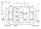
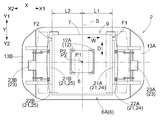
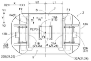
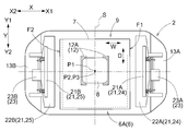
保持部12は、物品6のフランジ部8を保持する。物品6のフランジ部8は、幅方向Wにおいて本体部7の中央に取り付けられ、奥行方向Dにおいて本体部7の中央より前側(開口9側)に取り付けられている。そのため、保持物品6Aは、旋回操作部18による保持部12の旋回角度に応じて、並び方向第1側X1を向く第1側面F1と、並び方向第2側X2を向く第2側面F2と、の並び方向Xでの位置が変化する形状となっている。
物品搬送車2の並び方向X及び横幅方向Yの基準となる搬送車基準位置P2に対して、並び方向Xにおける搬送車基準位置P2と第1側面F1との離間距離を第1距離L1とし、並び方向Xにおける搬送車基準位置P2と第2側面F2との離間距離を第2距離L2とする。なお、本実施形態では、搬送車基準位置P2は、物品搬送車2の収容室13Cにおける並び方向Xの中心位置で且つ規制体21の横幅方向Yの中心位置である。そして、鉛直方向Z視において、収容室13Cの中心部は、搬送車基準位置P2に一致している。
図5に示すように、保持物品6Aの姿勢を、開口9が並び方向第2側X2に向く姿勢(第1姿勢)とした状態では、第1距離L1は第2距離L2より長くなる。図6に示すように、保持物品6Aの姿勢を、開口9が並び方向第1側X1に向く姿勢(第2姿勢)とした状態では、第1距離L1は第2距離L2より短くなる。図7に示すように、保持物品6Aの姿勢を、開口9を横幅方向第1側Y1に向く姿勢(第3姿勢)とした状態や、図8に示すように、保持物品6Aの姿勢を、開口9が横幅方向第2側Y2を向く姿勢(第4姿勢)
とした状態では、第1距離L1は第2距離L2と等しくなる。
とした状態では、第1距離L1は第2距離L2と等しくなる。
〔規制体〕
物品搬送車2は、上記に加えて更に、保持物品6Aの揺れを規制する一対の規制体21と、一対の規制体21を移動させる一対の調節用モータ23と、を備えている。そこで、次に、規制体21の動作について説明するが、その際、図3に示すように、保持部12が上方位置にある状態に基づいて説明する。
物品搬送車2は、上記に加えて更に、保持物品6Aの揺れを規制する一対の規制体21と、一対の規制体21を移動させる一対の調節用モータ23と、を備えている。そこで、次に、規制体21の動作について説明するが、その際、図3に示すように、保持部12が上方位置にある状態に基づいて説明する。
一対の規制体21は、鉛直方向Z視で保持物品6Aの両側に分かれて配置されている。ここでは、一対の規制体21として、第1規制体24と、第1規制体24に対して並び方向第2側X2に位置する第2規制体25と、が物品搬送車2に備えられている。保持物品6Aの並び方向第1側X1を向く面を第1側面F1とし、保持物品6Aの並び方向第2側X2を向く面を第2側面F2として、本実施形態では、第1規制体24は、保持物品6Aの第1側面F1に対向して配置される第1側面対向部21Aと、保持物品6Aの下面F3に対向して配置される第1下面対向部22Aと、を備えている。また、第2規制体25は、保持物品6Aの第2側面F2に対向して配置される第2側面対向部21Bと、保持物品6Aの下面F3に対向して配置される第2下面対向部22Bと、を備えている。
より具体的には、第1規制体24の第1側面対向部21Aは、第1側面F1に対向して配置されている。この第1側面対向部21Aは、保持物品6Aの第1側面F1の下端より下方から第1側面F1の下端より上方に亘って存在している。第2規制体25の第2側面対向部21Bは、第2側面F2に対向して配置されている。この第2側面対向部21Bは、保持物品6Aの第2側面F2の下端より下方から第2側面F2の下端より上方に亘って存在している。
第1下面対向部22A及び第2下面対向部22Bは、保持物品6Aの下面F3より下方に、下面F3に対して間隔を空けた状態で存在している。ここでは、第1下面対向部22Aは、第1側面対向部21Aの下端に連結されており、保持物品6Aの下面F3における第1側面F1側の部分に対向して配置されている。また、第2下面対向部22Bは、第2側面対向部21Bの下端に連結されており、保持物品6Aの下面F3における第2側面F2側の部分に対向して配置されている。
本実施形態では、第1側面対向部21A及び第2側面対向部21Bは、横幅方向Y及び鉛直方向Zに沿う姿勢の板状体により構成されている。また、第1下面対向部22A及び第2下面対向部22Bは、並び方向X及び横幅方向Yに沿う姿勢の板状体により構成されている。
第1側面対向部21Aは、第1下面対向部22Aにおける並び方向第2側X2の端部より並び方向第1側X1の部分に立設されている。第1側面対向部21Aが、保持物品6Aの第1側面F1に接触している状態では、第1下面対向部22Aにおける並び方向第2側X2の部分が、保持物品6Aの第1側面F1よりも並び方向第2側X2に位置している。
第2側面対向部21Bは、第2下面対向部22Bにおける並び方向第1側X1の端部より並び方向第2側X2の部分に立設されている。第2側面対向部21Bが、保持物品6Aの第2側面F2に接触している状態では、第2下面対向部22Bにおける並び方向第1側X1の部分が、保持物品6Aの第2側面F2よりも並び方向第1側X1に位置している。
第2側面対向部21Bは、第2下面対向部22Bにおける並び方向第1側X1の端部より並び方向第2側X2の部分に立設されている。第2側面対向部21Bが、保持物品6Aの第2側面F2に接触している状態では、第2下面対向部22Bにおける並び方向第1側X1の部分が、保持物品6Aの第2側面F2よりも並び方向第1側X1に位置している。
物品搬送車2は、一対の調節用モータ23として、第1規制体24を並び方向Xに沿って移動させる第1調節用モータ23Aと、第2規制体25を並び方向Xに沿って移動させる第2調節用モータ23Bと、を備えている。第1調節用モータ23Aは、第1壁部13A内に設置されており、第2調節用モータ23Bは、第2壁部13B内に設置されている。第1調節用モータ23Aは、第1規制体24を並び方向Xに移動させることで第1側面対向部21Aと第1下面対向部22Aとを一体的に並び方向Xに沿って移動させる。第2調節用モータ23Bは、第2規制体25を並び方向Xに移動させることで第2側面対向部21Bと第2下面対向部22Bとを一体的に並び方向Xに沿って移動させる。
ここで、並び方向Xにおける一対の規制体21の中央の位置を中央位置Sとする。より詳しくは、並び方向Xに対向する一対の規制体21(すなわち第1側面対向部21A及び第2側面対向部21B)の距離の中間点の位置を中央位置Sとする。一対の調節用モータ23は、一対の規制体21を各別に並び方向Xに移動させることで、並び方向Xにおける一対の規制体21の中央位置Sを調節することができる。また、一対の調節用モータ23は、一対の規制体21を各別に並び方向Xに移動させることで、並び方向Xにおける一対の規制体21の間隔も調節することができる。尚、一対の規制体21を移動させる規制体調節部は、一対の調節用モータ23及びそれぞれの調節用モータ23と規制体21とを連結する機構を含んで構成されている。
〔規制体の調節〕
図4に示すように、物品搬送車2は、図外の上位コントローラからの指令に基づいて物品搬送車2を制御する制御装置Hを備えている。制御装置Hは、保持物品6Aの姿勢に応じて、並び方向Xにおける一対の規制体21の中央位置Sを調節するために、一対の調節用モータ23を制御する。また、制御装置Hは、保持物品6Aの姿勢に応じて、横幅方向Yにおける保持部12の位置を調節するために、スライド用モータ17Bを制御する。スライド用モータ17Bを有するスライド操作部17は、保持物品6Aが収容室13Cの横幅方向Yの範囲内に収まるように保持部12の位置を調節する。
図4に示すように、物品搬送車2は、図外の上位コントローラからの指令に基づいて物品搬送車2を制御する制御装置Hを備えている。制御装置Hは、保持物品6Aの姿勢に応じて、並び方向Xにおける一対の規制体21の中央位置Sを調節するために、一対の調節用モータ23を制御する。また、制御装置Hは、保持物品6Aの姿勢に応じて、横幅方向Yにおける保持部12の位置を調節するために、スライド用モータ17Bを制御する。スライド用モータ17Bを有するスライド操作部17は、保持物品6Aが収容室13Cの横幅方向Yの範囲内に収まるように保持部12の位置を調節する。
本実施形態では、物品搬送車2が走行するときの保持物品6Aの姿勢として、第1姿勢(図5参照)、第1姿勢から180°旋回させた第2姿勢(図6参照)、第1姿勢から時計回りに90°旋回させた第3姿勢(図7参照)、第1姿勢から反時計回りに90°旋回させた第4姿勢(図8参照)と、がある。これらの保持物品6Aの姿勢の変化は、旋回操作部18により保持部12が縦軸心P1周りに旋回することで行われる。すなわち、本実施形態では、旋回操作部18は、保持部12及び保持物品6Aを、縦軸心P1周りに90°ずつ旋回させるように構成されている。
図5に示すように、保持物品6Aが第1姿勢の場合では、制御装置Hは、一対の規制体21を第1規制位置に移動させると共に、保持部12を第1保持位置に移動させるように、一対の調節用モータ23及びスライド用モータ17Bを制御する。第1規制位置は、一対の規制体21の中央位置Sが搬送車基準位置P2より並び方向第1側X1に位置し、且つ、第1規制体24が第1側面F1に接触すると共に第2規制体25が第2側面F2に接触する位置である。また、第1保持位置は、並び方向X及び横幅方向Yの双方において縦軸心P1が搬送車基準位置P2と同じ位置となる。また、第1保持位置は、並び方向Xにおいて物品中心P3が搬送車基準位置P2に対して並び方向第1側X1に位置し、横幅方向Yにおいて第1姿勢の物品6の物品中心P3と搬送車基準位置P2とが同じ位置となる。
図6に示すように、保持物品6Aが第2姿勢の場合では、制御装置Hは、一対の規制体21を第2規制位置に移動させると共に、保持部12を第2保持位置に移動させるように、一対の調節用モータ23及びスライド用モータ17Bを制御する。第2規制位置は、一対の規制体21の中央位置Sが搬送車基準位置P2より並び方向第2側X2に位置し、且つ、第1規制体24が第1側面F1に接触すると共に第2規制体25が第2側面F2に接触する位置である。また、第2保持位置は、並び方向X及び横幅方向Yの双方において縦軸心P1が搬送車基準位置P2と同じ位置となる。また、第2保持位置は、並び方向Xにおいて物品中心P3が搬送車基準位置P2に対して並び方向第2側X2に位置し、横幅方向Yにおいて物品中心P3と搬送車基準位置P2とが同じ位置となる。尚、本実施形態では、第2保持位置は、第1保持位置と同じ位置である。
図7に示すように、保持物品6Aが第3姿勢の場合では、制御装置Hは、一対の規制体21を第3規制位置に移動させると共に、保持部12を第3保持位置に移動させるように、一対の調節用モータ23及びスライド用モータ17Bを制御する。第3規制位置は、一対の規制体21の中央位置Sが搬送車基準位置P2に位置し、且つ、第1規制体24が第1側面F1に接触すると共に第2規制体25が第2側面F2に接触する位置である。また、第3保持位置は、並び方向Xにおいて縦軸心P1が搬送車基準位置P2と同じ位置となり、横幅方向Yにおいて縦軸心P1が搬送車基準位置P2に対して横幅方向第1側Y1となる。また、第3保持位置は、並び方向X及び横幅方向Yの双方において物品中心P3と搬送車基準位置P2とが同じ位置となる。尚、第3保持位置は、第1保持位置及び第2保持位置に対して横幅方向第1側Y1の位置である。
図8に示すように、保持物品6Aが第4姿勢の場合では、制御装置Hは、一対の規制体21を第4規制位置に移動させると共に、保持部12を第4保持位置に移動させるように、一対の調節用モータ23及びスライド用モータ17Bを制御する。第4規制位置は、一対の規制体21の中央位置Sが搬送車基準位置P2に位置し、且つ、第1規制体24が第1側面F1に接触すると共に第2規制体25が第2側面F2に接触する位置である。尚、本実施形態では、第4規制位置は並び方向Xにおいて第3規制位置と同じ位置である。また、第4保持位置は、並び方向Xにおいて縦軸心P1が搬送車基準位置P2と同じ位置となり、横幅方向Yにおいて縦軸心P1が搬送車基準位置P2に対して横幅方向第2側Y2となる。また、第4保持位置は、並び方向X及び横幅方向Yの双方において物品中心P3と搬送車基準位置P2とが同じ位置となる。尚、第4保持位置は、第1保持位置及び第2保持位置に対して横幅方向第2側Y2の位置である。
このように、制御装置Hは、保持物品6Aの姿勢に応じて、一対の規制体21の並び方向Xの位置を、一対の規制体21の位置を第1規制位置、第2規制位置、第3規制位置(第4規制位置も同じ)の3位置に移動させるべく、一対の調節用モータ23を制御する。また、制御装置Hは、保持物品6Aの姿勢に応じて、保持部12の横幅方向Yの位置を、第1保持位置(第2保持位置も同じ)、第3保持位置、第4保持位置の3位置に移動させるべく、スライド用モータ17Bを制御する。また、保持部12を上昇位置から下降位置に下降させる場合は、制御装置Hは、図9に示すように、一対の規制体21を保持物品6Aの並び方向Xの長さより広い間隔となる第5規制位置に移動させると共に、保持部12の横幅方向Yの位置及び姿勢が、支持台4等の保持物品6Aを搬送する搬送対象箇所に応じた位置及び姿勢に対応するように、一対の調節用モータ23、スライド用モータ17B及び旋回用モータ18Bを制御する。その結果、保持物品6Aが第1姿勢から第4姿勢の何れの姿勢の場合でも保持物品6Aは収容室13Cの横幅方向Yの範囲内に収まる。
2.その他の実施形態
次に、搬送装置のその他の実施形態について説明する。
次に、搬送装置のその他の実施形態について説明する。
(1)上記実施形態では、一対の規制体21の規制位置(第1から第4規制位置)を、一対の規制体21が保持物品6Aに接触する位置に設定したが、これに限定されない。第1規制体24が第1側面F1に対して離間して対向し、第2規制体25が第2側面F2に対して離間して対向するように、一対の規制体21の規制位置を設定してもよい。
(2)上記実施形態では、第1規制体24が、第1側面対向部21Aと第1下面対向部22Aとを備える構成を例として説明したが、第1規制体24が、第1側面対向部21Aと第1下面対向部22Aとのうちの第1側面対向部21Aのみを備えた構成であってもよい。同様に、第2規制体25が、第2側面対向部21Bと第2下面対向部22Bとのうちの第2側面対向部21Bのみを備えた構成であってもよい。
(3)上記実施形態では、物品6の鉛直方向Z視での形状が、幅方向Wの長さと奥行方向Dの長さとが等しい正方形状である場合を例として説明したが、これには限定されない。物品6の鉛直方向Z視の形状は、これ以外の形状であってもよく、例えば、物品6の鉛直方向Z視の形状が、長方形状等の幅方向Wの長さと奥行方向Dの長さが異なる矩形状であってもよく、或いは、三角形状、六角形状、八角形状等の各種多角形状であってもよい。また、一部の面が円弧状や台形状等に突出した形状等、縦軸心P1周りの外面の形状が規則的でない物品であってもよい。
(4)上記実施形態では、保持物品6Aの姿勢に応じて、並び方向Xにおける一対の規制体21の中央位置Sを調節する構成を例として説明したがこれには限定されない。例えば、物品6の鉛直方向Z視の形状が長方形状である場合等には、保持物品6Aの姿勢に応じて、並び方向Xにおける一対の規制体21の中央位置Sの調整に加えて並び方向Xにおける一対の規制体21の間隔を調節する構成とすると好適である。具体的には、第1規制位置及び第2規制位置における一対の規制体21の間隔と、第3規制位置及び第4規制位置における一対の規制体21の間隔とを異ならせると好適である。
(5)上記実施形態では、並び方向Xを、走行部11が走行する方向に沿う方向としたが、鉛直方向Z視で走行部11が走行する方向に対して交差する方向(例えば直交する方向)を並び方向Xとしてもよい。
(6)上記実施形態では、搬送装置を、天井に吊り下げられたレール1に沿って走行する物品搬送車2としたが、搬送装置は、レール1上をレール1に沿って走行する走行部11と物品6を保持する保持部12とを有していればよく、例えばスタッカークレーン等の他の装置としてもよい。
(7)上記実施形態では、旋回操作部18が、保持部12及び保持物品6Aを、縦軸心P1周りに90°ずつ旋回させる構成を例として説明した。しかし、これに限定されず、旋回操作部18が、保持部12及び保持物品6Aを、180°ずつ旋回させる構成であってもよい。或いは、旋回操作部18が、保持部12及び保持物品6Aを、45°や60°等、上記以外の角度で旋回させる構成であってもよい。
(8)上記実施形態では、保持調節部としてのスライド操作部17が、旋回操作部18による保持部12の旋回角度に応じて、横幅方向Yにおける保持部12の位置を調節する構成を例として説明した。しかしこれに限定されず、旋回操作部18による保持部12の旋回角度に関わらずスライド操作部17が保持部12を一定の位置に維持する構成とし、或いは、保持部12の旋回角度とは無関係にスライド操作部17が保持部12の位置を調節する構成としてもよい。
(9)なお、上述した各実施形態で開示された構成は、矛盾が生じない限り、他の実施形態で開示された構成と組み合わせて適用することも可能である。その他の構成に関しても、本明細書において開示された実施形態は全ての点で単なる例示に過ぎない。従って、本開示の趣旨を逸脱しない範囲内で、適宜、種々の改変を行うことが可能である。
3.上記実施形態の概要
以下、上記において説明した搬送装置の概要について説明する。
以下、上記において説明した搬送装置の概要について説明する。
搬送装置は、レールに沿って走行する走行部と、走行部に連結され且つ物品を保持する保持部と、前記保持部及び前記保持部に保持されている物品である保持物品を鉛直方向に沿う縦軸心周りに旋回させる旋回部と、鉛直方向視で前記保持物品の両側に分かれて配置される一対の規制体と、一対の前記規制体を移動させる規制体調節部と、を備え、
鉛直方向視で一対の前記規制体が並ぶ方向を並び方向とし、前記並び方向の一方側を並び方向第1側とし、その反対側を並び方向第2側とし、前記並び方向における一対の前記規制体の中央の位置を中央位置として、前記保持物品は、前記旋回部による前記保持部の旋回角度に応じて、前記並び方向第1側を向く第1側面と、前記並び方向第2側を向く第2側面と、の前記並び方向での位置が変化する形状であり、一対の前記規制体のうちの前記並び方向第1側にある第1規制体は、前記第1側面に対向して配置され、一対の前記規制体のうちの前記並び方向第2側にある第2規制体は、前記第2側面に対向して配置され、前記規制体調節部は、前記保持物品の姿勢に応じて、前記中央位置を調節する。
鉛直方向視で一対の前記規制体が並ぶ方向を並び方向とし、前記並び方向の一方側を並び方向第1側とし、その反対側を並び方向第2側とし、前記並び方向における一対の前記規制体の中央の位置を中央位置として、前記保持物品は、前記旋回部による前記保持部の旋回角度に応じて、前記並び方向第1側を向く第1側面と、前記並び方向第2側を向く第2側面と、の前記並び方向での位置が変化する形状であり、一対の前記規制体のうちの前記並び方向第1側にある第1規制体は、前記第1側面に対向して配置され、一対の前記規制体のうちの前記並び方向第2側にある第2規制体は、前記第2側面に対向して配置され、前記規制体調節部は、前記保持物品の姿勢に応じて、前記中央位置を調節する。
この構成によれば、旋回部により保持部が旋回することで、保持物品が縦軸心周りに旋回して保持物品の姿勢が変わり、保持物品の第1側面と第2側面との並び方向での位置が変化する。そこで、この構成によれば、規制体調節部が、保持物品の姿勢に応じて一対の規制体の中央位置を調節することで、一対の規制体を第1側面や第2側面に対応した位置に配置することができる。従って、保持部の旋回角度に関わらず、一対の規制体を適切な位置に配置することができる。そのため、保持部に保持されている物品が揺れた場合でも、その物品が規制体に接触することで物品の揺れを適切に規制することができる。
ここで、前記旋回部による前記保持部の旋回角度に応じて、鉛直方向視における前記並び方向に交差する方向における前記保持部の位置を調節する保持調節部を更に備えていると好適である。
この構成によれば、保持部が旋回して保持物品の姿勢が変わることで、並び方向に対して交差する方向において走行部に対して偏った位置に保持物品が配置されることになる場合でも、保持調節部により保持部の位置を調節することで、保持物品の走行部に対する位置の偏りを低減できる。従って、走行部の走行を適切に行い易い。
また、前記並び方向は、前記走行部が走行する方向に沿う方向であり、鉛直方向視における前記並び方向に対して直交する方向を横幅方向として、前記保持調節部は、前記横幅方向に沿って前記保持部を移動させると好適である。
この構成によれば、保持部が旋回して保持物品の姿勢が変わることで、横幅方向において走行部に対して偏った位置に保持物品が配置されることになる場合でも、保持調節部により保持部の位置を調節することで、保持物品の走行部に対する横幅方向の位置の偏りを低減できる。従って、走行部の走行を適切に行い易くなると共に、走行部の走行中に、走行経路に対して横幅方向の両側に設置された設置物に保持物品が干渉する可能性を低減できる。
また、前記保持物品を収容する収容室を形成する収容部を更に備え、前記保持調節部は、前記保持物品が前記収容室の前記横幅方向の範囲内に収まるように前記保持部の位置を調節すると好適である。
この構成によれば、保持部が旋回して保持物品の姿勢が変わることで、収容室における横幅方向の中央部に対して横幅方向に偏った位置に保持物品が配置されることになる場合でも、保持調節部により保持部の位置を調節することで、保持物品を収容室の横幅方向の範囲内に収めることができる。そのため、保持物品が収容部から横幅方向に突出することを防止できる。従って、走行部の走行中に、走行経路に対して横幅方向の両側に設置された設置物に保持物品が干渉する可能性を低減できる。
また、前記保持部は、物品の上端部を保持するように構成され、前記第1規制体は、前記保持物品の前記第1側面に対向して配置される第1側面対向部に加えて、前記保持物品の下面に対向して配置される第1下面対向部を更に備え、前記第2規制体は、前記保持物品の前記第2側面に対向して配置される第2側面対向部に加えて、前記保持物品の下面に対向して配置される第2下面対向部を更に備えていると好適である。
この構成によれば、物品の側面が第1側面対向部や第2側面対向部に接触することで、保持部に保持された物品の揺れを規制できる。また仮に、保持部による物品に対する保持が外れた場合でも、第1下面対向部と第2下面対向部とで物品を下方から受け止めることができるため、物品が落下することを抑制できる。また、第1下面対向部及び第2下面対向部は、規制体調節部により、保持物品の姿勢に応じて、並び方向における中央位置を調節できるため、保持部の旋回によって変化する保持物品の姿勢に関わらず、保持物品の落下を適切に抑制できる。
また、前記保持部は、前記レールより下方に位置し、前記保持部を前記走行部の近くの上昇位置と前記上昇位置より下方の下降位置とに昇降させる昇降駆動部を更に備え、前記第1規制体は、前記保持部が前記上昇位置にある状態で前記第1側面に対向して配置され、前記第2規制体は、前記保持部が前記上昇位置にある状態で前記第2側面に対向して配置されると好適である。
この構成によれば、搬送装置は、保持部を上昇位置にある状態で走行させ、保持部を上昇位置から下降位置に下降させることで、物品を下方に搬送することができる。そして、走行部を走行させる場合に、一対の規制体によって保持物品の揺れを適切に規制できる。
本開示に係る技術は、レールに沿って走行する走行部と、走行部に連結され且つ物品を保持する保持部と、前記保持部に保持されている物品を鉛直方向に沿う縦軸心周りに旋回させる旋回部と、を備えた搬送装置に利用することができる。
1:レール
2:物品搬送車(搬送装置)
6:物品
6A:保持物品
11:走行部
12:保持部
13:収容部
13C:収容室
17B:スライド用モータ(保持調節部)
18:旋回操作部(旋回部)
21:規制体
21A:第1側面対向部
21B:第2側面対向部
22A:第1下面対向部
22B:第2下面対向部
23:調節用モータ(規制体調節部)
24:第1規制体
25:第2規制体
F1:第1側面
F2:第2側面
F3:下面
P1:縦軸心
S:中央位置
X:並び方向
X1:並び方向第1側
X2:並び方向第2側
Z:鉛直方向
2:物品搬送車(搬送装置)
6:物品
6A:保持物品
11:走行部
12:保持部
13:収容部
13C:収容室
17B:スライド用モータ(保持調節部)
18:旋回操作部(旋回部)
21:規制体
21A:第1側面対向部
21B:第2側面対向部
22A:第1下面対向部
22B:第2下面対向部
23:調節用モータ(規制体調節部)
24:第1規制体
25:第2規制体
F1:第1側面
F2:第2側面
F3:下面
P1:縦軸心
S:中央位置
X:並び方向
X1:並び方向第1側
X2:並び方向第2側
Z:鉛直方向
Claims (6)
- レールに沿って走行する走行部と、
走行部に連結され且つ物品を保持する保持部と、
前記保持部及び前記保持部に保持されている物品である保持物品を鉛直方向に沿う縦軸心周りに旋回させる旋回部と、
鉛直方向視で前記保持物品の両側に分かれて配置される一対の規制体と、
一対の前記規制体を移動させる規制体調節部と、を備えた搬送装置であって、
鉛直方向視で一対の前記規制体が並ぶ方向を並び方向とし、前記並び方向の一方側を並び方向第1側とし、その反対側を並び方向第2側とし、前記並び方向における一対の前記規制体の中央の位置を中央位置として、
前記保持物品は、前記旋回部による前記保持部の旋回角度に応じて、前記並び方向第1側を向く第1側面と、前記並び方向第2側を向く第2側面と、の前記並び方向での位置が変化する形状であり、
一対の前記規制体のうちの前記並び方向第1側にある第1規制体は、前記第1側面に対向して配置され、
一対の前記規制体のうちの前記並び方向第2側にある第2規制体は、前記第2側面に対向して配置され、
前記規制体調節部は、前記保持物品の姿勢に応じて、前記中央位置を調節する搬送装置。 - 前記旋回部による前記保持部の旋回角度に応じて、鉛直方向視における前記並び方向に交差する方向における前記保持部の位置を調節する保持調節部を更に備えている請求項1に記載の搬送装置。
- 前記並び方向は、前記走行部が走行する方向に沿う方向であり、
鉛直方向視における前記並び方向に対して直交する方向を横幅方向として、
前記保持調節部は、前記横幅方向に沿って前記保持部を移動させる請求項2に記載の搬送装置。 - 前記保持物品を収容する収容室を形成する収容部を更に備え、
前記保持調節部は、前記保持物品が前記収容室の前記横幅方向の範囲内に収まるように前記保持部の位置を調節する請求項3に記載の搬送装置。 - 前記保持部は、物品の上端部を保持するように構成され、
前記第1規制体は、前記保持物品の前記第1側面に対向して配置される第1側面対向部に加えて、前記保持物品の下面に対向して配置される第1下面対向部を更に備え、
前記第2規制体は、前記保持物品の前記第2側面に対向して配置される第2側面対向部に加えて、前記保持物品の下面に対向して配置される第2下面対向部を更に備えている請求項1から4のいずれか一項に記載の搬送装置。 - 前記保持部は、前記レールより下方に位置し、
前記保持部を前記走行部の近くの上昇位置と前記上昇位置より下方の下降位置とに昇降させる昇降駆動部を更に備え、
前記第1規制体は、前記保持部が前記上昇位置にある状態で前記第1側面に対向して配置され、
前記第2規制体は、前記保持部が前記上昇位置にある状態で前記第2側面に対向して配置される請求項1から5のいずれか一項に記載の搬送装置。
Priority Applications (2)
| Application Number | Priority Date | Filing Date | Title |
|---|---|---|---|
| KR1020207022111A KR102513293B1 (ko) | 2018-03-08 | 2019-03-04 | 반송 장치 |
| CN201980015370.3A CN111741911B (zh) | 2018-03-08 | 2019-03-04 | 搬运装置 |
Applications Claiming Priority (2)
| Application Number | Priority Date | Filing Date | Title |
|---|---|---|---|
| JP2018-042066 | 2018-03-08 | ||
| JP2018042066A JP6939651B2 (ja) | 2018-03-08 | 2018-03-08 | 搬送装置 |
Publications (1)
| Publication Number | Publication Date |
|---|---|
| WO2019172155A1 true WO2019172155A1 (ja) | 2019-09-12 |
Family
ID=67847389
Family Applications (1)
| Application Number | Title | Priority Date | Filing Date |
|---|---|---|---|
| PCT/JP2019/008274 Ceased WO2019172155A1 (ja) | 2018-03-08 | 2019-03-04 | 搬送装置(transport device) |
Country Status (5)
| Country | Link |
|---|---|
| JP (1) | JP6939651B2 (ja) |
| KR (1) | KR102513293B1 (ja) |
| CN (1) | CN111741911B (ja) |
| TW (1) | TWI799528B (ja) |
| WO (1) | WO2019172155A1 (ja) |
Cited By (2)
| Publication number | Priority date | Publication date | Assignee | Title |
|---|---|---|---|---|
| CN112777194A (zh) * | 2019-11-07 | 2021-05-11 | 株式会社大福 | 物品搬运设备 |
| JP2023069914A (ja) * | 2021-11-08 | 2023-05-18 | 株式会社ダイフク | 物品搬送装置 |
Citations (4)
| Publication number | Priority date | Publication date | Assignee | Title |
|---|---|---|---|---|
| JPH02300091A (ja) * | 1989-05-16 | 1990-12-12 | Toshiba Corp | 移動クレーンの吊上げ位置制御装置 |
| JP2003128381A (ja) * | 2001-10-22 | 2003-05-08 | Daifuku Co Ltd | 搬送設備 |
| JP2015131702A (ja) * | 2014-01-10 | 2015-07-23 | 株式会社ダイフク | 搬送装置 |
| JP2016172607A (ja) * | 2015-03-16 | 2016-09-29 | 株式会社ダイフク | 物品搬送設備及び検査用治具 |
Family Cites Families (4)
| Publication number | Priority date | Publication date | Assignee | Title |
|---|---|---|---|---|
| JP3975532B2 (ja) * | 1997-11-12 | 2007-09-12 | アシスト シンコー株式会社 | 天井搬送車 |
| JP3981885B2 (ja) * | 2003-05-20 | 2007-09-26 | 株式会社ダイフク | 搬送装置 |
| JP5266680B2 (ja) * | 2007-07-23 | 2013-08-21 | 村田機械株式会社 | 搬送装置、搬送システム及び伸長機構 |
| JP6052143B2 (ja) * | 2013-11-20 | 2016-12-27 | 株式会社ダイフク | 直動回動装置 |
-
2018
- 2018-03-08 JP JP2018042066A patent/JP6939651B2/ja active Active
-
2019
- 2019-03-04 KR KR1020207022111A patent/KR102513293B1/ko active Active
- 2019-03-04 CN CN201980015370.3A patent/CN111741911B/zh active Active
- 2019-03-04 WO PCT/JP2019/008274 patent/WO2019172155A1/ja not_active Ceased
- 2019-03-07 TW TW108107625A patent/TWI799528B/zh active
Patent Citations (4)
| Publication number | Priority date | Publication date | Assignee | Title |
|---|---|---|---|---|
| JPH02300091A (ja) * | 1989-05-16 | 1990-12-12 | Toshiba Corp | 移動クレーンの吊上げ位置制御装置 |
| JP2003128381A (ja) * | 2001-10-22 | 2003-05-08 | Daifuku Co Ltd | 搬送設備 |
| JP2015131702A (ja) * | 2014-01-10 | 2015-07-23 | 株式会社ダイフク | 搬送装置 |
| JP2016172607A (ja) * | 2015-03-16 | 2016-09-29 | 株式会社ダイフク | 物品搬送設備及び検査用治具 |
Cited By (4)
| Publication number | Priority date | Publication date | Assignee | Title |
|---|---|---|---|---|
| CN112777194A (zh) * | 2019-11-07 | 2021-05-11 | 株式会社大福 | 物品搬运设备 |
| CN112777194B (zh) * | 2019-11-07 | 2024-04-26 | 株式会社大福 | 物品搬运设备 |
| JP2023069914A (ja) * | 2021-11-08 | 2023-05-18 | 株式会社ダイフク | 物品搬送装置 |
| JP7487721B2 (ja) | 2021-11-08 | 2024-05-21 | 株式会社ダイフク | 物品搬送装置 |
Also Published As
| Publication number | Publication date |
|---|---|
| KR102513293B1 (ko) | 2023-03-22 |
| CN111741911A (zh) | 2020-10-02 |
| TWI799528B (zh) | 2023-04-21 |
| TW201943638A (zh) | 2019-11-16 |
| KR20200128517A (ko) | 2020-11-13 |
| JP6939651B2 (ja) | 2021-09-22 |
| JP2019156516A (ja) | 2019-09-19 |
| CN111741911B (zh) | 2023-01-17 |
Similar Documents
| Publication | Publication Date | Title |
|---|---|---|
| US11476141B2 (en) | Rail-guided trolley system, and rail-guided trolley | |
| KR102501700B1 (ko) | 천장 반송차 및 천장 반송차 시스템 | |
| US10699928B2 (en) | Transport system with crane | |
| US9117853B2 (en) | Transfer system | |
| US9896283B2 (en) | Article transport facility | |
| JP6849065B2 (ja) | 搬送システム及び搬送方法 | |
| JP7327660B2 (ja) | 天井搬送車及び天井搬送システム | |
| JP2018049943A (ja) | 物品搬送設備 | |
| WO2019003753A1 (ja) | 搬送システム及び搬送方法 | |
| WO2022149305A1 (ja) | 天井保管システム | |
| WO2019172155A1 (ja) | 搬送装置(transport device) | |
| CN115427329A (zh) | 输送车系统 | |
| US20210362949A1 (en) | Article Transport Facility | |
| JP2018039656A (ja) | 容器収納設備 | |
| WO2022201904A1 (ja) | 搬送車(transport vehicle) | |
| CN110294415B (zh) | 物品搬运设备 | |
| WO2012014561A1 (ja) | 搬送システム | |
| JP2018131104A (ja) | 物品搬送設備 | |
| WO2019244562A1 (ja) | 搬送車 | |
| JP6593288B2 (ja) | 物品搬送装置 | |
| JP2023074704A (ja) | 物品搬送装置 | |
| JP2021178711A (ja) | 容器取扱設備 |
Legal Events
| Date | Code | Title | Description |
|---|---|---|---|
| 121 | Ep: the epo has been informed by wipo that ep was designated in this application |
Ref document number: 19764286 Country of ref document: EP Kind code of ref document: A1 |
|
| NENP | Non-entry into the national phase |
Ref country code: DE |
|
| 122 | Ep: pct application non-entry in european phase |
Ref document number: 19764286 Country of ref document: EP Kind code of ref document: A1 |