WO2019167738A1 - 流体圧シリンダにおけるシール構造及びその流体圧シリンダ - Google Patents
流体圧シリンダにおけるシール構造及びその流体圧シリンダ Download PDFInfo
- Publication number
- WO2019167738A1 WO2019167738A1 PCT/JP2019/006246 JP2019006246W WO2019167738A1 WO 2019167738 A1 WO2019167738 A1 WO 2019167738A1 JP 2019006246 W JP2019006246 W JP 2019006246W WO 2019167738 A1 WO2019167738 A1 WO 2019167738A1
- Authority
- WO
- WIPO (PCT)
- Prior art keywords
- packing
- sliding surface
- seal
- chamber
- piston
- Prior art date
- Legal status (The legal status is an assumption and is not a legal conclusion. Google has not performed a legal analysis and makes no representation as to the accuracy of the status listed.)
- Ceased
Links
Images


Classifications
-
- F—MECHANICAL ENGINEERING; LIGHTING; HEATING; WEAPONS; BLASTING
- F16—ENGINEERING ELEMENTS AND UNITS; GENERAL MEASURES FOR PRODUCING AND MAINTAINING EFFECTIVE FUNCTIONING OF MACHINES OR INSTALLATIONS; THERMAL INSULATION IN GENERAL
- F16J—PISTONS; CYLINDERS; SEALINGS
- F16J1/00—Pistons; Trunk pistons; Plungers
- F16J1/005—Pistons; Trunk pistons; Plungers obtained by assembling several pieces
- F16J1/006—Pistons; Trunk pistons; Plungers obtained by assembling several pieces of different materials
- F16J1/008—Pistons; Trunk pistons; Plungers obtained by assembling several pieces of different materials with sealing lips
-
- F—MECHANICAL ENGINEERING; LIGHTING; HEATING; WEAPONS; BLASTING
- F15—FLUID-PRESSURE ACTUATORS; HYDRAULICS OR PNEUMATICS IN GENERAL
- F15B—SYSTEMS ACTING BY MEANS OF FLUIDS IN GENERAL; FLUID-PRESSURE ACTUATORS, e.g. SERVOMOTORS; DETAILS OF FLUID-PRESSURE SYSTEMS, NOT OTHERWISE PROVIDED FOR
- F15B15/00—Fluid-actuated devices for displacing a member from one position to another; Gearing associated therewith
- F15B15/08—Characterised by the construction of the motor unit
- F15B15/14—Characterised by the construction of the motor unit of the straight-cylinder type
- F15B15/1423—Component parts; Constructional details
- F15B15/1447—Pistons; Piston to piston rod assemblies
- F15B15/1452—Piston sealings
-
- F—MECHANICAL ENGINEERING; LIGHTING; HEATING; WEAPONS; BLASTING
- F16—ENGINEERING ELEMENTS AND UNITS; GENERAL MEASURES FOR PRODUCING AND MAINTAINING EFFECTIVE FUNCTIONING OF MACHINES OR INSTALLATIONS; THERMAL INSULATION IN GENERAL
- F16J—PISTONS; CYLINDERS; SEALINGS
- F16J15/00—Sealings
- F16J15/16—Sealings between relatively-moving surfaces
- F16J15/164—Sealings between relatively-moving surfaces the sealing action depending on movements; pressure difference, temperature or presence of leaking fluid
-
- F—MECHANICAL ENGINEERING; LIGHTING; HEATING; WEAPONS; BLASTING
- F16—ENGINEERING ELEMENTS AND UNITS; GENERAL MEASURES FOR PRODUCING AND MAINTAINING EFFECTIVE FUNCTIONING OF MACHINES OR INSTALLATIONS; THERMAL INSULATION IN GENERAL
- F16J—PISTONS; CYLINDERS; SEALINGS
- F16J15/00—Sealings
- F16J15/16—Sealings between relatively-moving surfaces
- F16J15/18—Sealings between relatively-moving surfaces with stuffing-boxes for elastic or plastic packings
-
- F—MECHANICAL ENGINEERING; LIGHTING; HEATING; WEAPONS; BLASTING
- F16—ENGINEERING ELEMENTS AND UNITS; GENERAL MEASURES FOR PRODUCING AND MAINTAINING EFFECTIVE FUNCTIONING OF MACHINES OR INSTALLATIONS; THERMAL INSULATION IN GENERAL
- F16J—PISTONS; CYLINDERS; SEALINGS
- F16J15/00—Sealings
- F16J15/16—Sealings between relatively-moving surfaces
- F16J15/32—Sealings between relatively-moving surfaces with elastic sealings, e.g. O-rings
- F16J15/3204—Sealings between relatively-moving surfaces with elastic sealings, e.g. O-rings with at least one lip
- F16J15/3232—Sealings between relatively-moving surfaces with elastic sealings, e.g. O-rings with at least one lip having two or more lips
-
- F—MECHANICAL ENGINEERING; LIGHTING; HEATING; WEAPONS; BLASTING
- F16—ENGINEERING ELEMENTS AND UNITS; GENERAL MEASURES FOR PRODUCING AND MAINTAINING EFFECTIVE FUNCTIONING OF MACHINES OR INSTALLATIONS; THERMAL INSULATION IN GENERAL
- F16J—PISTONS; CYLINDERS; SEALINGS
- F16J15/00—Sealings
- F16J15/16—Sealings between relatively-moving surfaces
- F16J15/32—Sealings between relatively-moving surfaces with elastic sealings, e.g. O-rings
- F16J15/324—Arrangements for lubrication or cooling of the sealing itself
-
- F—MECHANICAL ENGINEERING; LIGHTING; HEATING; WEAPONS; BLASTING
- F16—ENGINEERING ELEMENTS AND UNITS; GENERAL MEASURES FOR PRODUCING AND MAINTAINING EFFECTIVE FUNCTIONING OF MACHINES OR INSTALLATIONS; THERMAL INSULATION IN GENERAL
- F16J—PISTONS; CYLINDERS; SEALINGS
- F16J15/00—Sealings
- F16J15/16—Sealings between relatively-moving surfaces
- F16J15/32—Sealings between relatively-moving surfaces with elastic sealings, e.g. O-rings
- F16J15/3268—Mounting of sealing rings
-
- F—MECHANICAL ENGINEERING; LIGHTING; HEATING; WEAPONS; BLASTING
- F16—ENGINEERING ELEMENTS AND UNITS; GENERAL MEASURES FOR PRODUCING AND MAINTAINING EFFECTIVE FUNCTIONING OF MACHINES OR INSTALLATIONS; THERMAL INSULATION IN GENERAL
- F16J—PISTONS; CYLINDERS; SEALINGS
- F16J15/00—Sealings
- F16J15/46—Sealings with packing ring expanded or pressed into place by fluid pressure, e.g. inflatable packings
- F16J15/48—Sealings with packing ring expanded or pressed into place by fluid pressure, e.g. inflatable packings influenced by the pressure within the member to be sealed
-
- F—MECHANICAL ENGINEERING; LIGHTING; HEATING; WEAPONS; BLASTING
- F16—ENGINEERING ELEMENTS AND UNITS; GENERAL MEASURES FOR PRODUCING AND MAINTAINING EFFECTIVE FUNCTIONING OF MACHINES OR INSTALLATIONS; THERMAL INSULATION IN GENERAL
- F16J—PISTONS; CYLINDERS; SEALINGS
- F16J9/00—Piston-rings, e.g. non-metallic piston-rings, seats therefor; Ring sealings of similar construction
- F16J9/12—Details
- F16J9/20—Rings with special cross-section; Oil-scraping rings
-
- F—MECHANICAL ENGINEERING; LIGHTING; HEATING; WEAPONS; BLASTING
- F15—FLUID-PRESSURE ACTUATORS; HYDRAULICS OR PNEUMATICS IN GENERAL
- F15B—SYSTEMS ACTING BY MEANS OF FLUIDS IN GENERAL; FLUID-PRESSURE ACTUATORS, e.g. SERVOMOTORS; DETAILS OF FLUID-PRESSURE SYSTEMS, NOT OTHERWISE PROVIDED FOR
- F15B15/00—Fluid-actuated devices for displacing a member from one position to another; Gearing associated therewith
- F15B15/08—Characterised by the construction of the motor unit
- F15B15/14—Characterised by the construction of the motor unit of the straight-cylinder type
- F15B15/1423—Component parts; Constructional details
- F15B15/1428—Cylinders
-
- F—MECHANICAL ENGINEERING; LIGHTING; HEATING; WEAPONS; BLASTING
- F16—ENGINEERING ELEMENTS AND UNITS; GENERAL MEASURES FOR PRODUCING AND MAINTAINING EFFECTIVE FUNCTIONING OF MACHINES OR INSTALLATIONS; THERMAL INSULATION IN GENERAL
- F16J—PISTONS; CYLINDERS; SEALINGS
- F16J15/00—Sealings
- F16J15/16—Sealings between relatively-moving surfaces
- F16J15/32—Sealings between relatively-moving surfaces with elastic sealings, e.g. O-rings
- F16J15/3284—Sealings between relatively-moving surfaces with elastic sealings, e.g. O-rings characterised by their structure; Selection of materials
Definitions
- the present invention relates to a fluid pressure cylinder in which a piston is slidably accommodated in a cylinder hole, between a sliding surface formed by an outer peripheral surface of the piston and a sliding surface formed by an inner peripheral surface of the cylinder hole.
- the present invention relates to a seal structure and its fluid pressure cylinder.
- a fluid pressure cylinder that slides a piston in a cylinder hole by using the pressure of a compressed fluid such as compressed air has been widely known conventionally as disclosed in, for example, Patent Document 1 and the like.
- a cylinder hole is partitioned into a pair of chambers by a piston.
- a seal member made of a rubber elastic material, that is, an annular packing is attached to the sliding surface consisting of the outer peripheral surface around the axis of the piston, whereby the sliding surface and the axis of the cylinder hole are The leakage of the compressed fluid is prevented from occurring between the pair of chambers through the sliding surface formed by the inner peripheral surface.
- the piston sliding surface is secured in order to ensure a sealing property between the piston sliding surface and the cylinder hole sliding surface.
- the outer diameter of the packing attached to is formed larger than the inner diameter of the sliding surface of the cylinder hole. That is, regardless of whether or not the piston is in operation, the packing is always pressed against the sliding surface in an elastically deformed state.
- the packing may be permanently deformed or fixed to the sliding surface if the state of being stopped by being pressed against the sliding surface of the cylinder hole is maintained for a long time.
- the packing is directly affected by the state of the sliding surface (the roughness of the sliding surface, the state of the lubricating film, etc.). Due to the sliding friction and non-uniformity of the lubricating film, sliding wear and twisting of the packing may occur, resulting in damage and deterioration of the packing, or adversely affecting piston operation (decreasing operating efficiency, cogging operation, etc.) There is a fear.
- the technical problem of the present invention is to provide a seal structure between a piston and a cylinder hole in a fluid pressure cylinder that can realize a smoother operation of the piston and can extend the life of the packing. And providing a fluid pressure cylinder having such a sealing structure.
- the present invention provides a seal structure between a piston in a fluid pressure cylinder and a cylinder hole in which the piston is slidably accommodated in the axial direction, and sandwiches the piston in the cylinder hole.
- a first chamber and a second chamber are formed on both sides in the axial direction, a sliding surface is formed by an outer peripheral surface around the axis of the piston, and an inner peripheral surface around the axis of the cylinder hole
- a sliding surface on which the piston slides with its sliding surface facing is formed, and a concave groove is formed on the sliding surface of the piston so as to surround the shaft and open in the radial direction.
- the concave groove accommodates a base end portion on the inner peripheral side of the packing made of rubber elastic material, and a front end portion on the outer peripheral side of the packing protrudes from the sliding surface.
- a first seal portion and the second seal portion in the packing accommodated in the groove are provided with a first seal portion, and a second seal portion is provided around the shaft at a side end portion on the second chamber side.
- the outer diameter of the packing is smaller than the diameter of the sliding surface of the cylinder hole, and in the state where the compressed fluid is supplied to either the first chamber or the second chamber, The side end of the chamber to which the fluid is supplied extends in the radial direction due to elastic deformation caused by the pressure of the fluid, whereby the fluid is supplied from the first seal portion and the second seal portion.
- the chamber-side seal portion is configured to narrow the gap formed between the cylinder hole and the sliding surface of the cylinder hole, or to contact the sliding surface. is there.
- the packing and the groove are symmetrical with respect to the radial direction in a cross section along the axis, and the groove is formed from the sliding surface in the radial direction.
- the depth to the bottom wall surface with which the proximal end of the packing abuts is formed to be 1/2 or more of the height from the proximal end to the distal end of the packing.
- the concave groove has a pair of side wall surfaces that rise in a radial direction from both axial ends of the bottom wall surface and face each other, and the bottom wall surface and the pair of side wall surfaces are 90. An angle of less than or equal to degrees.
- the maximum width of the base end portion accommodated in the groove in the packing is smaller than the minimum width between the pair of side wall surfaces in the groove.
- the base end of the packing may be fixed to the bottom wall surface of the groove by adhesion.
- the packing has a pair of side end faces facing each other in parallel with each other at both axial ends thereof, and the axial direction in a cross section along the axis.
- the tip end portion of the packing is formed with a tip end surface facing the sliding surface, and the tip end surface has a side end on the first chamber side in the axial direction.
- a first seal portion is formed, and the second seal portion is formed at a side end portion of the distal end surface on the second chamber side in the axial direction.
- the first seal portion is formed by a first protrusion protruding from the tip surface toward the sliding surface
- the second seal portion is formed from the tip surface. It is formed by a second ridge protruding toward the sliding surface.
- the tips of the first and second ridges are respectively formed by corners forming an acute angle with the pair of side end surfaces of the packing. More preferably, the distance from the sliding surface to the tips of the first and second ridges is formed to be equal to each other, and the tip surface of the packing is parallel to the sliding surface. The height from the tip surface to the tip of the first and second ridges is formed to be equal to each other, and the first and second ridges are in the axial direction. Are spaced apart from each other.
- the first protrusion and the second protrusion may be formed in a wedge shape in which the axial width gradually decreases from the tip surface toward the tip, or on the tip surface of the packing.
- a labyrinth protrusion that forms a labyrinth seal may be provided between the first protrusion and the second protrusion.
- the pair of side end surfaces of the packing may each be provided with an annular constriction groove that communicates with the opening of the concave groove. In this case, more preferably, the constriction groove is formed by a concave curved surface. Is formed.
- the fluid pressure cylinder has an air supply port connected to a cylinder hole, and the sonic conductance of the air supply port is C1, and the packing and the sliding surface are When the sonic conductance of the leakage flow path formed between the sliding surface and the sliding surface by the gap is C2, the ratio C1 / C2 of these sonic conductances is always 2.0 or more.
- a wear ring is provided on the sliding surface of the piston at a position adjacent to the packing in the axial direction, and the outer diameter of the wear ring is such that the compressed fluid is in the first chamber and the first chamber. It is formed larger than the outer diameter of the packing in a state where it is not supplied to any of the two chambers.
- the fluid pressure cylinder provided with the said seal structure can be provided.
- the outer diameter of the packing having the first seal portion and the second seal portion is formed smaller than the inner diameter of the cylinder hole in the state of being accommodated in the concave groove.
- the side end of the packing in which the compressed fluid is supplied that is, the side end portion on the high pressure chamber side
- Due to the elastic deformation caused by the pressure of the compressed fluid it expands in the radial direction, so that the seal part on the high pressure chamber side of the first seal part and the second seal part is between the sliding surface of the cylinder hole.
- the gap formed in is narrowed or abutted against the sliding surface.
- sliding surface condition sliding surface roughness, lubrication film condition, etc.
- the piston operation decrease in operating efficiency, cogging operation, etc.
- the packing sliding
- smoother operation of the piston can be realized, and the life of the packing can be extended.
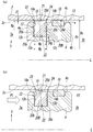
- FIG. 1 is a schematic cross-sectional view along an axis showing one embodiment of a fluid pressure cylinder according to the present invention. It is an enlarged view of the A section in Drawing 1, and is a rough sectional view showing a 1st embodiment of a seal structure concerning the present invention.
- (A) shows the non-operating state of the piston where the pressure of the compressed fluid does not act on the piston, and (b) shows the operating state of the piston where the pressure of the compressed fluid acts on the piston.
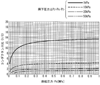
- FIG. 8 is a model diagram of a fluid pressure cylinder used in the analysis of FIG. 7. It is a graph which shows the relationship between supply pressure Ps of compressed fluid, fall pressure (DELTA) P2, and conductance ratio C1 / C2.
- a fluid pressure cylinder 1 having a seal structure includes a body 2 in which a cylinder hole 3 extending in the axis L direction is formed, and a cylinder hole 3 in the axis L direction. And a piston 4 accommodated slidably.
- the cylinder hole 3 is defined by an inner peripheral surface 3c, and is partitioned by the piston 4 into a first chamber 3a on the rod side and a second chamber 3b on the head side.
- a rod 5 extending to the first chamber 3a side along the axis L is fixed to the piston 4, and a rod cover is provided at an opening located at the end of the cylinder hole 3 on the first chamber 3a side.
- 6 is airtightly fitted and fixed.
- a bearing hole 6a for penetrating and supporting the rod 5 is provided in the rod cover 6 along the axis L.
- the rod 5 is airtight in the axis L direction with respect to the bearing hole 6a. It is slidably inserted.
- the end of the cylinder hole 3 on the second chamber 3b side is airtightly closed by an end plate 2a molded integrally with the body 2.
- the body 2 is selectively connected to an external pressure source or the atmosphere via a switching valve to supply a compressed fluid such as compressed air into the cylinder hole 3 or from the cylinder hole 3.
- An air supply / exhaust port for operating the piston 4 by exhausting the compressed fluid is provided.
- a first port 7 and a second port 8 are provided as the air supply / exhaust ports.
- the first port 7 has a first flow path 7a with a reduced cross-sectional area and is connected to the first chamber 3a.
- the second port 8 has a second flow path with a reduced cross-sectional area. It has 8a and is connected to the second chamber 3b.
- annular flow path 9 formed by a gap between the outer peripheral surface of the rod cover 6 and the inner peripheral surface of the cylinder hole 3 is formed on the first chamber 3a side of the rod cover 6 in the axis L direction. Is provided.
- the annular flow path 9 communicates with the first chamber 3 a, and the first flow path 7 a of the first port 7 is connected to the annular flow path 9.
- the second flow path 8a of the second port 8 is connected to the cylinder hole 3 in the vicinity of the end plate 2a.
- the cylinder hole 3 and the piston 4 have the same shape in a cross section perpendicular to the axis L, and have a circular shape, an elliptical shape, or a track shape.
- the cylinder hole 3 is defined by a sliding surface 3c composed of an inner peripheral surface having a radius Rc centered on the axis L, while the piston 4 is A slide comprising a first surface 4a defining the first chamber 3a on which the rod 5 is provided, a second surface 4b defining the second chamber 3b, and an outer peripheral surface having a radius Rs centered on the axis L. And a moving surface 4c.
- the radius Rs of the sliding surface 4c is formed to be slightly smaller than the radius of the sliding surface 3c of the cylinder hole 3 (ie, the inner radius of the cylinder hole 3) Rc. And the sliding surface 4c are opposed to each other with a gap interposed therebetween (in this application, for the sake of convenience, the distance from the axis L is uniformly “radius” ”).
- a packing 20 is mounted as an annular seal member that seals between the sliding surface 3 c of the cylinder hole 3. Further, at the position adjacent to the packing 20 in the axis L direction of the sliding surface 4c, seizure and galling of the piston 4 due to contact between the sliding surface 4c and the sliding surface 3c is prevented, and A wear ring 10 for protecting the packing 20 is attached.
- the material of the packing 20 is not particularly limited as long as it is a rubber elastic material that exhibits a sealing function. For example, nitrile rubber, fluorine rubber, or the like can be used.
- the material of the wear ring 10 is not particularly limited as long as it functions as a bearing. For example, a fluororesin (PTFE) or a phenol resin with cloth can be used.
- the piston 4 is located at the end of the first chamber 3a side and the second chamber 3b side in the axis L direction on the second surface 4b of the piston 4 and the inner surface of the rod cover 6 defining the first chamber 3a.
- Cushion members 11a and 11b are provided to alleviate the impact caused by the collision when it arrives.
- a lip-shaped seal member 6b opened toward the first chamber 3a side is mounted in a groove provided on the inner peripheral surface of the bearing hole 6a of the rod cover 6, and the outer periphery of the rod 5 is It is in sliding contact with the surface.
- an annular first concave groove 12 that opens in the radial direction Y is provided around the axis L on the sliding surface 4 c of the piston 4.
- the packing 20 is mounted in the concave groove 12.
- an annular second concave groove 13 that similarly opens in the radial direction Y is located around the axis L at a position closer to the second chamber 3b than the first concave groove 12 in the axis L direction of the sliding surface 4c.
- the wear ring 10 is mounted in the second concave groove 13.
- the first concave groove 12 is provided in a ring shape around the axis L and extends flatly along the axis L, and is perpendicular to both ends of the bottom wall surface 12a in the axis L direction.
- the first side wall surface 12b on the first chamber 3a side and the second side wall surface 12c on the second chamber 3b side, which extend in the radial direction Y (perpendicular to the axis L) and face each other, are configured. That is, the sliding surface 4c and the pair of side wall surfaces 12b and 12c formed in planes parallel to each other intersect at a right angle, thereby forming the opening of the first concave groove 12.
- the first concave groove 12 is formed in a rectangular shape that is bilaterally symmetric with respect to the central axis in the radial direction Y in a cross section along the axis L.
- the bottom wall surface 12a of the first concave groove 12 is formed to have a radius Rg centered on the axis L, and therefore the distance Rs-Rg from the sliding surface 4c to the bottom wall surface 12a is This corresponds to the depth Dg of one concave groove 12.
- the first concave groove 12 has a uniform depth Dg over the entire circumferential direction of the piston 4.
- the groove width Wg along the axis L of the first concave groove 12 is also uniformly formed over the entire depth from the opening to the bottom wall surface 12a.
- the first concave groove 12 is not limited to the above-described form.
- the pair of side wall surfaces 12b and 12c intersects with the bottom wall surface 12a and the sliding surface 4c at an acute angle to form a groove width Wg. May be formed so as to gradually narrow from the bottom wall surface 12a toward the opening.
- the packing 20 is formed so that the inner radius thereof is smaller than the radius Rg of the bottom wall surface 12a of the first concave groove 12 when the packing 20 is not installed in the first concave groove 12.
- the circumferential length of the inner circumferential surface (that is, the base end surface) 20a of the packing 20 is shorter than the circumferential length of the bottom wall surface 12a of the first concave groove 12. Therefore, as shown in FIGS. 2 to 5, when the packing 20 is mounted in the first concave groove 12, the packing 20 made of a rubber elastic material is extended in the circumferential direction, and the inner peripheral surface 20a thereof is the bottom wall surface. 12a is elastically pressed. Thereby, the sealing performance between the inner peripheral surface 20a of the packing 20 and the bottom wall surface 12a of the first concave groove 12 is ensured.
- the packing 20 is formed in a solid rectangular shape that is substantially symmetrical with respect to the central axis in the radial direction Y in the cross section along the axis L. . That is, the outer shape of the packing 20 is formed by the inner peripheral surface of the packing 20, and is formed by the base end surface 20 a that forms an annulus around the axis L and that extends flatly along the axis L, and the outer peripheral surface of the packing 20.
- a distal end surface 20d that is formed around the axis L and that extends flatly along the axis L is connected to one end of the base end surface 20a and the distal end surface 20d in the axis L direction, and the first chamber 3a side
- the first side end surface 20b extending in a radial direction Y toward the surface and the other end in the axis L direction of the base end surface 20a and the front end surface 20d are connected to each other, and the diameter is directed to the second chamber 3b side. It is formed by four surfaces with a second side end surface 20c extending in a plane in the direction Y.
- the base end face 20a is pressed against the bottom wall face 12a and is parallel to the tip face 20d.
- the pair of side end faces 20b and 20c are parallel to each other and face away from each other, and are perpendicular to the base end face 20a and the tip end face 20d, of which the first side end face 20b is the first concave.
- the first side wall surface 12b of the groove 12 is opposed, and the second side end surface 20c is opposed to the second side wall surface 12c.
- the outer radius of the packing 20 mounted in the first concave groove 12 (the outer radius of the tip surface 20d in the first embodiment) is Rp
- the base pressed against the bottom wall surface 12a of the packing 20 is used.
- the first concave groove 12 is accommodated. At this time, it is preferable that the depth Dg of the first concave groove 12 is not less than 1 ⁇ 2 of Hp of the height of the entire packing 20 because the packing 20 can be prevented from coming off the concave groove 12.
- the packing 20 has a uniform width Wp in the axis L direction from the base end surface 20a to the front end surface 20d in the radial direction Y, and this width Wp. Is formed smaller than the width Wg of the first concave groove 12. That is, in the present invention, the maximum width Wpmax in the radial direction Y of the packing 20 is formed smaller than the minimum width Wgmin in the radial direction Y of the first concave groove 12. Therefore, the packing 20 has an axial L direction between the first side wall surface 12b and the second side wall surface 12c of the first groove 12 by the fluid pressure in the first chamber 3a and the second chamber 3b of the cylinder hole 3. Can be moved back and forth.
- the end portion on the first side end face 20b side (first chamber 3a side) of the tip portion 21 of the packing 20 forms an annular first seal portion 23 around the axis L, and the second side is also the same.
- An end portion on the end face 20c side (second chamber 3b side) forms an annular second seal portion 24 around the axis L.
- first seal portion 23 includes a right-angled corner where the tip end surface 20d and the first side end surface 20b intersect
- second seal portion 24 includes the tip end surface 20d and the second side end surface. It includes a right-angled corner that intersects 20c.
- an annular second concave for accommodating the wear ring 10 and attaching to the sliding surface 4c is provided on the sliding surface 4c of the piston 4 closer to the second side end surface 20c than the first concave groove 12 is.
- a groove 13 is provided around. From the viewpoint of protecting the packing 20 as described above, the wear ring 10 mounted in the second concave groove 13 is not elastically deformed by the fluid pressure in the chambers 3a and 3b. It is preferable that the outer diameter Rp of the packing 20 is larger than the outer radius Rp. In the present application, the wear ring 10 does not have a sealing property.
- the fluid pressure P1 causes a clockwise moment force in the drawing around the opening edge of the second side wall surface 12c to act on the packing 20, and the first side end surface 20b of the packing 20 And the first end portion on the first chamber 3a side including the first seal portion 23 elastically extend in the radial direction Y (that is, toward the sliding surface 3c of the cylinder hole 3).
- the space between the sliding surface 4c of the piston 4 and the sliding surface 3c of the cylinder hole 3 is sealed, so that the piston 4 is moved to the second chamber 3b by the fluid pressure P1 of the first chamber 3a. Drive to the side. At that time, the second chamber 3 b of the cylinder hole 3 is communicated with the atmosphere through the second port 8.
- the fluid pressure P2 in the second chamber 3b acts on the second side end face 20c of the packing 20. Therefore, the packing 20 moves in the first concave groove 12 toward the first side wall surface 12b and is pressed against the first side wall surface 12b. At the same time, a counterclockwise moment force in the drawing around the opening edge of the first side wall surface 12b acts on the packing 20 due to the fluid pressure P2, and the second side end surface of the packing 20
- the side end portion on the second chamber 3b side including 20c and the second seal portion 24 elastically extends in the radial direction Y (that is, toward the sliding surface 3c of the cylinder hole 3).
- the piston 4 is driven toward the first chamber 3a side by the fluid pressure P2 of the second chamber 3b.
- the first chamber 3 a of the cylinder hole 3 communicates with the atmosphere through the first port 7.
- the sliding friction generated between the packing 20 and the sliding surface 3c is as much as possible. Can be suppressed.
- the state of the sliding surface 3c (roughness of the sliding surface 3c, the state of the lubricating film, etc.) affects the operation of the piston 4 (decrease in operating efficiency, cogging operation, etc.) and affects the packing 20. Negative effects (damage or deterioration due to sliding wear or twisting) can be suppressed as much as possible. Therefore, in the fluid pressure cylinder 1, a smoother operation of the piston 4 can be realized, and the life of the packing 20 can be extended.
- the portion where the seal structure of the second embodiment is different from the seal structure of the first embodiment is mainly in the form of first and second seal portions provided around the front end portion 21 of the packing.
- the first seal portion is directed in the radial direction Y from the end portion on the first side end surface 20b side of the front end surface 20d of the packing 20A (ie, in the radial direction Y).
- the ring-shaped first protrusion 23a is integrally formed (toward the sliding surface 3c of the cylinder hole 3).
- the second seal portion is formed by an annular second protrusion 24a that is integrally projected in the radial direction Y from the end portion on the second side end surface 20c side of the tip end surface 20d. That is, in the axis L direction, the protrusions 23a and 24a are spaced apart from both side ends of the tip surface 20d with a tip surface 20d flat in the axial direction interposed therebetween.
- the packing 20A having the first protrusions 23a and the second protrusions 24a is also symmetrical with respect to the central axis in the radial direction Y in the cross section along the axis L. Therefore, the distances from the tip surface 20d to the tips of the ridges 23a, 24a are equal to each other, and the distances from the sliding surface 3c of the cylinder hole 3 to the tips of the ridges 23a, 24a are also the same. Are equal to each other. And the distance from the axis
- the pair of protrusions 23a, 24a are wedges whose width in the axis L direction gradually decreases from the proximal end on the distal end surface 20d toward the distal end on the sliding surface 3c side. It is formed into a shape.
- the first ridge 23a is erected with an outer wall formed of the first side end face 20b and perpendicular to the tip end face 20d, and inclined from the tip end face 20d toward the first side end face 20b. Formed by the inner wall.
- the second ridge 24a includes an outer wall formed of the second side end face 20c and perpendicular to the tip end face 20d, and an inner wall provided to be inclined from the tip end face 20d toward the second side end face 20c.
- the packing 20A according to the second embodiment is the same as the packing 20 according to the first embodiment, except that a groove having an inverted isosceles trapezoidal cross section with the tip surface 20d as the bottom surface is formed at the center of the outer circumferential surface in the axis L direction. And the front-end
- the first and second protrusions 23a and 24a as the first and second seal portions formed in this way are placed in the respective chambers 3a and 3b of the adjacent cylinder holes 3 as shown in FIG.
- the necessary sealing performance between the sliding surface 3c of the cylinder hole 3 and the sliding surface 4c of the piston 4 can be ensured.
- the first side end surface 20b and the second side end surface 20c of the packing 20B have an annular first having the same radius from the axis L.
- a constriction groove 14a and a second constriction groove 14b are provided around the circumference.
- the first and second constricted grooves 14a and 14b are for accelerating the expansion of the packing 20B in the radial direction Y as described above when the fluid pressure in the chambers 3a and 3b acts on the side end surfaces 20b and 20c.
- the constricted portion 15 is formed in which the width Wp of the packing is narrowed by being opposed to the same height from the base end face 20a.
- the packing 20B including the pair of constricted grooves 14a and 14b is also formed symmetrically with respect to the central axis of the transverse section.
- the pair of constricted grooves 14a and 14b is formed by a concave concave surface, preferably an arc surface, in which the groove walls are formed, and the width of the constricted portion 15 is less than 1/2 of the total width Wp of the packing 20B.
- the opening width of the constricted grooves 14a and 14b on the side end faces 20b and 20c is smaller than 1/2 of the total height Hp of the packing 20B.
- the whole of the pair of constricted grooves 14a and 14b and the constricted portion 15 is provided at the base end portion 22 of the packing 20B, specifically, the height direction of the packing 20B. It is formed in the vicinity of the opening in the first concave groove 12 on the outer peripheral side from the center of the first concave groove 12.
- the base end surface 20a of the packing 20B is the first concave in a state where the central axis of the cross section of the packing 20B and the central axis of the first concave groove 12 are aligned.
- the groove 12 is fixed to the bottom wall surface 12a by adhesion. That is, the packing 20B is fixed at the center in the width direction of the first concave groove 12, and is between the first side end face 20b and the first side wall face 12b and between the second side end face 20c and the second side wall face 12c.
- Are formed with voids of the same width ( (Wg ⁇ Wp) / 2). Therefore, the pair of constricted grooves 14 a and 14 b communicate with the opening of the first concave groove 12.
- the compressed fluid is selectively supplied into the respective chambers 3a and 3b of the cylinder hole 3 as shown in FIG. Then, due to the fluid pressures P1 and P2, a clockwise or counterclockwise moment force acts on the packing 20B in the drawing. Then, as in the case of the first embodiment, the side end of the packing 20B on the side where the fluid pressures P1 and P2 are applied extends. At that time, the constricted grooves 14a and 14b on the side on which the fluid pressures P1 and P2 act are expanded by the fluid pressure, but the constricted grooves on the opposite side are contracted, so that the extension of the side end portion is further promoted. Will be.
- the packing 20B since a gap is formed between the packing 20B and the first concave groove 12 at the opposite side end where the fluid pressure does not act, the side end where the fluid pressure acts is also formed. Extension is not hindered. Further, since the packing 20B is fixed to the center of the first concave groove 12 in the width direction by adhesion, the base end surface (inner peripheral surface) 20a of the packing 20B is fixed to the bottom of the first concave groove 12 by the moment force and the fluid pressure. It is possible to prevent floating from the wall surface 12a.
- the first protrusion 23a on the tip surface 20d of the packing 20A is formed.
- the labyrinth protrusion 25 may be erected in the radial direction Y at a position between the first protrusion 24a and the second protrusion 24a.
- the labyrinth protrusion 25 is preferably formed in an annular shape around the axis L at the center in the axis L direction of the tip surface 20d (on the central axis of the transverse section of the packing 20A) in parallel with the protrusions 23a and 24a. Is formed.
- the transverse cross section is formed in a wedge shape, such as an isosceles triangle having an acute apex angle, which is symmetrical and has a width gradually narrowing toward the tip.
- the height of the labyrinth protrusion 25 from the tip surface 20d to the tip is preferably equal to or higher than the height of the ridges 23a and 24a.
- C1 is the sonic conductance of the port connected to the head-side pressure chamber
- C2 is the gap ⁇ between the packing and the sliding surface of the cylinder hole, so that the sliding surface of the piston and the sliding surface are Sonic conductance of the leakage flow path formed between the moving surface
- C3 is the sonic conductance of the port connected to the rod side pressure chamber
- Ps is the supply pressure
- P1 is the pressure of the rod side pressure chamber
- P2 is the head side
- the pressure in the pressure chamber and Pe represents the exhaust pressure.
- FIG. 7 shows an analysis result when air is supplied from the head-side port to the head-side pressure chamber and exhausted from the port connected to the rod-side pressure chamber.
- This analysis result is an analysis with a cylinder diameter of 32 mm, but it is confirmed that the conductance ratio C1 / C2 is substantially independent of the cylinder diameter if the pressure drop ⁇ P2 is constant. . That is, if the pressure drop ⁇ P2 is the same, the graph will substantially overlap the graph of FIG. 7 even if the cylinder diameter is changed. Therefore, the graph of other cylinder diameters is omitted here.
- the analysis model of FIG. 6 when the air is supplied from the rod side port to the rod side pressure chamber and the air is exhausted from the port connected to the head side pressure chamber, the same result as in FIG. 7 is obtained. .
- the conductance ratio C1 / C2 increases as the drop pressure ⁇ P2 decreases.
- the conductance ratio C1 / C2 gradually increases as the supply pressure Ps increases and then converges to a substantially constant value.
- the pressure in the pressure chamber of the cylinder it is known that if the pressure drop ⁇ P2 is up to about 20 kPa, there is no practical effect on the use of the cylinder. Regardless, it can be seen that the range of the conductance ratio C1 / C2 in which the pressure drop ⁇ P2 can be suppressed to about 20 kPa or less is 2.0 or more. Therefore, also in each of the above embodiments, the size of the gap ⁇ formed between the seal portion of the packing and the sliding surface of the cylinder hole in a range where the conductance ratio C1 / C2 is always 2.0 or more. It is desirable to set
- the seal structure in the fluid pressure cylinder according to the present invention has been described.
- the present invention is not limited to the above-described embodiments, and various design changes can be made without departing from the scope of the claims. Needless to say.
- the rod is provided only on one side of the piston, but the rod may be provided on both sides of the piston.
- the seal portions 23 (23a) and 24 (24a) desirably have a corner portion that forms a right angle or an acute angle with the side end surfaces 20b and 20c of the packing 20A. Is not to be done.
Landscapes
- Engineering & Computer Science (AREA)
- General Engineering & Computer Science (AREA)
- Mechanical Engineering (AREA)
- Physics & Mathematics (AREA)
- Fluid Mechanics (AREA)
- Architecture (AREA)
- Chemical & Material Sciences (AREA)
- Combustion & Propulsion (AREA)
- Sealing Devices (AREA)
- Actuator (AREA)
Priority Applications (7)
| Application Number | Priority Date | Filing Date | Title |
|---|---|---|---|
| RU2020131523A RU2020131523A (ru) | 2018-02-28 | 2019-02-20 | Уплотнительная конструкция в гидравлическом цилиндре и гидравлический цилиндр |
| MX2020008846A MX2020008846A (es) | 2018-02-28 | 2019-02-20 | Estructura de sello en cilindro hidraulico y el cilindro hidraulico. |
| US16/976,299 US20210003152A1 (en) | 2018-02-28 | 2019-02-20 | Seal structure in hydraulic cylinder, and said hydraulic cylinder |
| BR112020017504-8A BR112020017504A2 (pt) | 2018-02-28 | 2019-02-20 | Estrutura de vedação em cilindro hidráulico e referido cilindro hidráulico |
| KR1020207024257A KR20200124232A (ko) | 2018-02-28 | 2019-02-20 | 유체압 실린더에 있어서의 실링 구조 및 그 유체압 실린더 |
| EP19761281.5A EP3760881A4 (en) | 2018-02-28 | 2019-02-20 | SEAL ARRANGEMENT IN A HYDRAULIC CYLINDER AND SAID HYDRAULIC CYLINDER |
| CN201980014918.2A CN111771064A (zh) | 2018-02-28 | 2019-02-20 | 流体压缸中的密封构造及该流体压缸 |
Applications Claiming Priority (2)
| Application Number | Priority Date | Filing Date | Title |
|---|---|---|---|
| JP2018-035914 | 2018-02-28 | ||
| JP2018035914A JP6997977B2 (ja) | 2018-02-28 | 2018-02-28 | 流体圧シリンダにおけるシール構造及びその流体圧シリンダ |
Publications (1)
| Publication Number | Publication Date |
|---|---|
| WO2019167738A1 true WO2019167738A1 (ja) | 2019-09-06 |
Family
ID=67806147
Family Applications (1)
| Application Number | Title | Priority Date | Filing Date |
|---|---|---|---|
| PCT/JP2019/006246 Ceased WO2019167738A1 (ja) | 2018-02-28 | 2019-02-20 | 流体圧シリンダにおけるシール構造及びその流体圧シリンダ |
Country Status (10)
| Country | Link |
|---|---|
| US (1) | US20210003152A1 (https=) |
| EP (1) | EP3760881A4 (https=) |
| JP (1) | JP6997977B2 (https=) |
| KR (1) | KR20200124232A (https=) |
| CN (1) | CN111771064A (https=) |
| BR (1) | BR112020017504A2 (https=) |
| MX (1) | MX2020008846A (https=) |
| RU (1) | RU2020131523A (https=) |
| TW (1) | TW201937084A (https=) |
| WO (1) | WO2019167738A1 (https=) |
Cited By (1)
| Publication number | Priority date | Publication date | Assignee | Title |
|---|---|---|---|---|
| WO2022104182A1 (en) * | 2020-11-16 | 2022-05-19 | Caterpillar Inc. | Integrated cylinder piston and bearing as a hydraulic cushion |
Families Citing this family (4)
| Publication number | Priority date | Publication date | Assignee | Title |
|---|---|---|---|---|
| CN112648304B (zh) * | 2019-10-11 | 2024-08-23 | 舍弗勒技术股份两合公司 | 密封装置及液压活塞装置 |
| CN114810718B (zh) * | 2022-05-25 | 2025-08-26 | 广州德马威工业装备制造有限公司 | 一种多重密封耐高压液体密封件 |
| US12595811B2 (en) * | 2024-04-30 | 2026-04-07 | Rosenboom Machine & Tool, Inc. | Seal plate method for communicating retract oil to retract side of piston in hydraulic cylinder |
| US12590775B2 (en) | 2024-07-16 | 2026-03-31 | Raytheon Company | Trigger lock |
Citations (6)
| Publication number | Priority date | Publication date | Assignee | Title |
|---|---|---|---|---|
| EP0635663A1 (en) * | 1993-06-28 | 1995-01-25 | American Cylinder Co., Inc. | Air cylinder with anti-blowby piston |
| JPH0914451A (ja) * | 1995-07-04 | 1997-01-14 | Ckd Corp | ピストン及びシリンダ |
| JPH09144884A (ja) * | 1995-11-24 | 1997-06-03 | Nok Corp | ピストン |
| JP2010014202A (ja) * | 2008-07-03 | 2010-01-21 | Nok Corp | 密封装置 |
| JP2011027127A (ja) | 2009-07-21 | 2011-02-10 | Smc Corp | パッキン |
| JP2011241914A (ja) * | 2010-05-19 | 2011-12-01 | Smc Corp | 流体圧機器 |
Family Cites Families (9)
| Publication number | Priority date | Publication date | Assignee | Title |
|---|---|---|---|---|
| AU431969B2 (en) * | 1968-08-06 | 1973-01-24 | Seal ring | |
| CH612256A5 (https=) * | 1977-06-27 | 1979-07-13 | Occident Ets | |
| JPH0497165U (https=) * | 1991-01-22 | 1992-08-21 | ||
| DE4137461C2 (de) * | 1991-11-14 | 1994-06-16 | Freudenberg Carl Fa | Dichtungsanordnung für einen Separator |
| JP2537236Y2 (ja) * | 1992-03-31 | 1997-05-28 | エスエムシー株式会社 | スプール弁 |
| JP2008133920A (ja) * | 2006-11-29 | 2008-06-12 | Smc Corp | 流体圧シリンダ |
| WO2008072738A1 (ja) * | 2006-12-14 | 2008-06-19 | Nok Corporation | 密封装置及び密封装置の製造方法 |
| CN103388604A (zh) * | 2012-05-07 | 2013-11-13 | 北京纽希液压技术研究所 | 一种液压缸 |
| CN205841759U (zh) * | 2016-07-15 | 2016-12-28 | 无锡恩福油封有限公司 | 密封装置 |
-
2018
- 2018-02-28 JP JP2018035914A patent/JP6997977B2/ja active Active
-
2019
- 2019-02-19 TW TW108105407A patent/TW201937084A/zh unknown
- 2019-02-20 CN CN201980014918.2A patent/CN111771064A/zh active Pending
- 2019-02-20 RU RU2020131523A patent/RU2020131523A/ru unknown
- 2019-02-20 US US16/976,299 patent/US20210003152A1/en not_active Abandoned
- 2019-02-20 EP EP19761281.5A patent/EP3760881A4/en not_active Withdrawn
- 2019-02-20 WO PCT/JP2019/006246 patent/WO2019167738A1/ja not_active Ceased
- 2019-02-20 MX MX2020008846A patent/MX2020008846A/es unknown
- 2019-02-20 KR KR1020207024257A patent/KR20200124232A/ko not_active Withdrawn
- 2019-02-20 BR BR112020017504-8A patent/BR112020017504A2/pt not_active IP Right Cessation
Patent Citations (6)
| Publication number | Priority date | Publication date | Assignee | Title |
|---|---|---|---|---|
| EP0635663A1 (en) * | 1993-06-28 | 1995-01-25 | American Cylinder Co., Inc. | Air cylinder with anti-blowby piston |
| JPH0914451A (ja) * | 1995-07-04 | 1997-01-14 | Ckd Corp | ピストン及びシリンダ |
| JPH09144884A (ja) * | 1995-11-24 | 1997-06-03 | Nok Corp | ピストン |
| JP2010014202A (ja) * | 2008-07-03 | 2010-01-21 | Nok Corp | 密封装置 |
| JP2011027127A (ja) | 2009-07-21 | 2011-02-10 | Smc Corp | パッキン |
| JP2011241914A (ja) * | 2010-05-19 | 2011-12-01 | Smc Corp | 流体圧機器 |
Non-Patent Citations (1)
| Title |
|---|
| See also references of EP3760881A4 |
Cited By (1)
| Publication number | Priority date | Publication date | Assignee | Title |
|---|---|---|---|---|
| WO2022104182A1 (en) * | 2020-11-16 | 2022-05-19 | Caterpillar Inc. | Integrated cylinder piston and bearing as a hydraulic cushion |
Also Published As
| Publication number | Publication date |
|---|---|
| CN111771064A (zh) | 2020-10-13 |
| BR112020017504A2 (pt) | 2020-12-22 |
| KR20200124232A (ko) | 2020-11-02 |
| RU2020131523A (ru) | 2022-03-28 |
| EP3760881A4 (en) | 2021-11-17 |
| JP2019152233A (ja) | 2019-09-12 |
| JP6997977B2 (ja) | 2022-01-18 |
| TW201937084A (zh) | 2019-09-16 |
| MX2020008846A (es) | 2020-10-01 |
| US20210003152A1 (en) | 2021-01-07 |
| EP3760881A1 (en) | 2021-01-06 |
Similar Documents
| Publication | Publication Date | Title |
|---|---|---|
| WO2019167738A1 (ja) | 流体圧シリンダにおけるシール構造及びその流体圧シリンダ | |
| US20180058586A1 (en) | Buffer ring | |
| WO2008069234A1 (ja) | パッキン及びシーリングシステム | |
| WO2015004963A1 (ja) | 軸シール | |
| JP2019152233A5 (https=) | ||
| JP5177391B2 (ja) | ピストンシール構造 | |
| JP6735673B2 (ja) | 密閉組立体、及びアクチュエータ | |
| US11221072B2 (en) | Arrangement structure for seal member | |
| US11913553B2 (en) | Spool-type switching valve | |
| JP5531386B2 (ja) | シーリングシステム | |
| CN112513503B (zh) | 滑阀式切换阀中的密封构造及该滑阀式切换阀 | |
| JP5211927B2 (ja) | 密封装置 | |
| JP2012137121A (ja) | 密封装置 | |
| JP2012215188A (ja) | 密封構造 | |
| JPH08145186A (ja) | シ−ル装置 | |
| JP2020020429A5 (https=) | ||
| JPH0529415Y2 (https=) | ||
| JP2006112486A (ja) | 密封装置 | |
| JP2024070981A (ja) | 密封部材及びこれを用いた密封構造 | |
| JP2019138388A (ja) | 密封装置 | |
| JP2015183711A (ja) | ロッドレスシリンダ用ピストンシール | |
| JP2007092791A (ja) | シールリング | |
| JPH0640416U (ja) | 空気圧シリンダのシール装置 | |
| JP2019196789A (ja) | パッキン | |
| WO2018008520A1 (ja) | シール材の配置構造 |
Legal Events
| Date | Code | Title | Description |
|---|---|---|---|
| 121 | Ep: the epo has been informed by wipo that ep was designated in this application |
Ref document number: 19761281 Country of ref document: EP Kind code of ref document: A1 |
|
| ENP | Entry into the national phase |
Ref document number: 20207024257 Country of ref document: KR Kind code of ref document: A |
|
| NENP | Non-entry into the national phase |
Ref country code: DE |
|
| ENP | Entry into the national phase |
Ref document number: 2019761281 Country of ref document: EP Effective date: 20200928 |
|
| REG | Reference to national code |
Ref country code: BR Ref legal event code: B01A Ref document number: 112020017504 Country of ref document: BR |
|
| ENP | Entry into the national phase |
Ref document number: 112020017504 Country of ref document: BR Kind code of ref document: A2 Effective date: 20200827 |