WO2019150753A1 - 内視鏡 - Google Patents
内視鏡 Download PDFInfo
- Publication number
- WO2019150753A1 WO2019150753A1 PCT/JP2018/044576 JP2018044576W WO2019150753A1 WO 2019150753 A1 WO2019150753 A1 WO 2019150753A1 JP 2018044576 W JP2018044576 W JP 2018044576W WO 2019150753 A1 WO2019150753 A1 WO 2019150753A1
- Authority
- WO
- WIPO (PCT)
- Prior art keywords
- rotating shaft
- shaft
- hole
- endoscope
- housing
- Prior art date
- Legal status (The legal status is an assumption and is not a legal conclusion. Google has not performed a legal analysis and makes no representation as to the accuracy of the status listed.)
- Ceased
Links
Images


Classifications
-
- A—HUMAN NECESSITIES
- A61—MEDICAL OR VETERINARY SCIENCE; HYGIENE
- A61B—DIAGNOSIS; SURGERY; IDENTIFICATION
- A61B1/00—Instruments for performing medical examinations of the interior of cavities or tubes of the body by visual or photographical inspection, e.g. endoscopes; Illuminating arrangements therefor
- A61B1/00064—Constructional details of the endoscope body
- A61B1/00071—Insertion part of the endoscope body
- A61B1/0008—Insertion part of the endoscope body characterised by distal tip features
- A61B1/00098—Deflecting means for inserted tools
-
- A—HUMAN NECESSITIES
- A61—MEDICAL OR VETERINARY SCIENCE; HYGIENE
- A61B—DIAGNOSIS; SURGERY; IDENTIFICATION
- A61B1/00—Instruments for performing medical examinations of the interior of cavities or tubes of the body by visual or photographical inspection, e.g. endoscopes; Illuminating arrangements therefor
- A61B1/00002—Operational features of endoscopes
- A61B1/00004—Operational features of endoscopes characterised by electronic signal processing
- A61B1/00006—Operational features of endoscopes characterised by electronic signal processing of control signals
-
- A—HUMAN NECESSITIES
- A61—MEDICAL OR VETERINARY SCIENCE; HYGIENE
- A61B—DIAGNOSIS; SURGERY; IDENTIFICATION
- A61B1/00—Instruments for performing medical examinations of the interior of cavities or tubes of the body by visual or photographical inspection, e.g. endoscopes; Illuminating arrangements therefor
- A61B1/00064—Constructional details of the endoscope body
- A61B1/00071—Insertion part of the endoscope body
- A61B1/0008—Insertion part of the endoscope body characterised by distal tip features
- A61B1/00087—Tools
-
- A—HUMAN NECESSITIES
- A61—MEDICAL OR VETERINARY SCIENCE; HYGIENE
- A61B—DIAGNOSIS; SURGERY; IDENTIFICATION
- A61B1/00—Instruments for performing medical examinations of the interior of cavities or tubes of the body by visual or photographical inspection, e.g. endoscopes; Illuminating arrangements therefor
- A61B1/00064—Constructional details of the endoscope body
- A61B1/00071—Insertion part of the endoscope body
- A61B1/0008—Insertion part of the endoscope body characterised by distal tip features
- A61B1/00101—Insertion part of the endoscope body characterised by distal tip features the distal tip features being detachable
-
- A—HUMAN NECESSITIES
- A61—MEDICAL OR VETERINARY SCIENCE; HYGIENE
- A61B—DIAGNOSIS; SURGERY; IDENTIFICATION
- A61B1/00—Instruments for performing medical examinations of the interior of cavities or tubes of the body by visual or photographical inspection, e.g. endoscopes; Illuminating arrangements therefor
- A61B1/00064—Constructional details of the endoscope body
- A61B1/0011—Manufacturing of endoscope parts
-
- A—HUMAN NECESSITIES
- A61—MEDICAL OR VETERINARY SCIENCE; HYGIENE
- A61B—DIAGNOSIS; SURGERY; IDENTIFICATION
- A61B1/00—Instruments for performing medical examinations of the interior of cavities or tubes of the body by visual or photographical inspection, e.g. endoscopes; Illuminating arrangements therefor
- A61B1/00131—Accessories for endoscopes
- A61B1/00137—End pieces at either end of the endoscope, e.g. caps, seals or forceps plugs
-
- A—HUMAN NECESSITIES
- A61—MEDICAL OR VETERINARY SCIENCE; HYGIENE
- A61B—DIAGNOSIS; SURGERY; IDENTIFICATION
- A61B1/00—Instruments for performing medical examinations of the interior of cavities or tubes of the body by visual or photographical inspection, e.g. endoscopes; Illuminating arrangements therefor
- A61B1/012—Instruments for performing medical examinations of the interior of cavities or tubes of the body by visual or photographical inspection, e.g. endoscopes; Illuminating arrangements therefor characterised by internal passages or accessories therefor
- A61B1/018—Instruments for performing medical examinations of the interior of cavities or tubes of the body by visual or photographical inspection, e.g. endoscopes; Illuminating arrangements therefor characterised by internal passages or accessories therefor for receiving instruments
-
- A—HUMAN NECESSITIES
- A61—MEDICAL OR VETERINARY SCIENCE; HYGIENE
- A61B—DIAGNOSIS; SURGERY; IDENTIFICATION
- A61B8/00—Diagnosis using ultrasonic, sonic or infrasonic waves
- A61B8/12—Diagnosis using ultrasonic, sonic or infrasonic waves in body cavities or body tracts, e.g. by using catheters
-
- G—PHYSICS
- G02—OPTICS
- G02B—OPTICAL ELEMENTS, SYSTEMS OR APPARATUS
- G02B23/00—Telescopes, e.g. binoculars; Periscopes; Instruments for viewing the inside of hollow bodies; Viewfinders; Optical aiming or sighting devices
- G02B23/24—Instruments or systems for viewing the inside of hollow bodies, e.g. fibrescopes
-
- A—HUMAN NECESSITIES
- A61—MEDICAL OR VETERINARY SCIENCE; HYGIENE
- A61B—DIAGNOSIS; SURGERY; IDENTIFICATION
- A61B1/00—Instruments for performing medical examinations of the interior of cavities or tubes of the body by visual or photographical inspection, e.g. endoscopes; Illuminating arrangements therefor
- A61B1/005—Flexible endoscopes
- A61B1/0051—Flexible endoscopes with controlled bending of insertion part
-
- A—HUMAN NECESSITIES
- A61—MEDICAL OR VETERINARY SCIENCE; HYGIENE
- A61B—DIAGNOSIS; SURGERY; IDENTIFICATION
- A61B1/00—Instruments for performing medical examinations of the interior of cavities or tubes of the body by visual or photographical inspection, e.g. endoscopes; Illuminating arrangements therefor
- A61B1/06—Instruments for performing medical examinations of the interior of cavities or tubes of the body by visual or photographical inspection, e.g. endoscopes; Illuminating arrangements therefor with illuminating arrangements
- A61B1/0661—Endoscope light sources
Definitions
- the present invention relates to an endoscope.
- an endoscope in which a treatment tool such as a forceps can protrude from the distal end of an insertion portion to be inserted into a subject (for example, see Patent Document 1).
- the operation wire provided in the insertion portion moves by operating the operation portion provided on the proximal end side of the insertion portion, and the rotating shaft rotates to raise the raising base.
- the rotating shaft is supported by the shaft hole of the housing located between the position where the wire is connected and the raising base.
- the rotation axis may tilt. If the rotation shaft is tilted, watertightness may not be ensured or rotation failure may occur. For this reason, the technique which prevents that a rotating shaft inclines was calculated
- the present invention has been made in view of the above, and an object of the present invention is to provide an endoscope that prevents the rotation shaft for raising the elevator from being tilted.
- an endoscope is an endoscope that is capable of inserting a treatment tool and is disposed at a distal end of the endoscope, and the treatment A distal end rigid portion in which an opening from which the instrument protrudes is formed; a treatment instrument raising base that is located in the opening and changes a direction in which the treatment instrument protrudes by contacting the treatment instrument; and one end of the treatment instrument A rotation shaft fixed to the device raising base and rotatable integrally with the treatment device raising base; an arm portion fixed to the rotation shaft and rotating the rotation shaft in response to an operation on the operation portion; A first bearing portion that is positioned closer to the treatment instrument elevator base than the arm portion in the axial direction of the rotation shaft, and has a first shaft hole that rotatably supports the rotation shaft; and the shaft In the direction, the first bearing portion with respect to the arm portion A housing having a second bearing portion that is located on the opposite side and that is formed with a second shaft hole that
- the endoscope according to one aspect of the present invention is characterized in that the rotating shaft is fixed to the arm portion by a spring pin or a pin screw.
- the arm portion is formed with a through hole having a flat portion extending in a direction perpendicular to the axial direction, and the outer periphery of the rotating shaft is formed on the outer periphery of the rotating shaft.
- a planar portion extending in a direction orthogonal to the axial direction is formed, and the through-hole and the rotating shaft are in a state where the planar portion of the through-hole and the planar portion of the rotating shaft are opposed to each other. Are fitted.
- a housing seal that keeps the distal end hard portion and the housing watertight is located between the distal end hard portion and the first bearing portion. It is characterized by.
- the endoscope according to one aspect of the present invention is characterized in that a fitting groove into which the seal member is fitted is formed on the outer periphery of the rotating shaft.
- the rotation axis of the treatment instrument raising base, the rotation axis of the arm unit, and the axes of the first shaft hole and the second shaft hole are provided. It is characterized by being on the same straight line.
- the endoscope according to one aspect of the present invention is characterized in that the housing is detachably fixed to the hard tip portion.
- the endoscope includes an ultrasonic transducer.
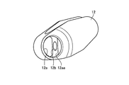
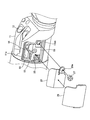
- FIG. 1 is a schematic diagram showing a configuration of an endoscope according to an embodiment of the present invention.
- FIG. 2 is a schematic partial cross-sectional view of the distal end portion of the endoscope shown in FIG.
- FIG. 3 is a side view of the forceps raising base shown in FIG.
- FIG. 4 is a perspective view of the rotating shaft shown in FIG.
- FIG. 5 is a perspective view of the arm portion shown in FIG.
- FIG. 6 is a perspective view of the housing shown in FIG.
- FIG. 7 is a diagram for explaining an endoscope assembling method.
- FIG. 8 is a diagram for explaining an endoscope assembling method.
- FIG. 9 is a diagram for explaining an endoscope assembling method.
- FIG. 10 is a diagram for explaining an endoscope assembling method.
- FIG. 10 is a diagram for explaining an endoscope assembling method.
- FIG. 11 is a diagram for explaining an endoscope assembling method.
- FIG. 12 is a diagram for explaining an endoscope assembling method.
- FIG. 13 is a diagram for explaining an endoscope assembling method.
- FIG. 14 is a diagram illustrating a partial configuration of the distal end portion of the endoscope according to the first modification of the embodiment.
- FIG. 15 is a diagram illustrating a partial configuration of the distal end portion of the endoscope according to the second modification of the embodiment.
- Embodiments of an endoscope according to the present invention will be described below with reference to the drawings. Note that the present invention is not limited to these embodiments.
- the present invention can be generally applied to an endoscope including a treatment instrument raising base.
- FIG. 1 is a schematic diagram showing a configuration of an endoscope according to an embodiment of the present invention.
- the endoscope 1 is provided with an imaging unit at a distal end, an insertion unit 2 inserted into a subject, an operation unit 3 connected to a proximal end side of the insertion unit 2, and an operation unit 3.
- a universal cord 4 extending from the side, a connector portion connected to the universal cord 4 and connected to an observation device for controlling the endoscope 1 and a light source device for supplying illumination light to the endoscope 1 5 is provided.
- FIG. 1 is a schematic diagram showing a configuration of an endoscope according to an embodiment of the present invention.
- the endoscope 1 is provided with an imaging unit at a distal end, an insertion unit 2 inserted into a subject, an operation unit 3 connected to a proximal end side of the insertion unit 2, and an operation unit 3.
- a universal cord 4 extending from the side, a connector portion connected to the universal cord 4 and connected to an observation device for controlling
- insertion direction the direction in which the insertion portion 2 is inserted in the longitudinal direction of the endoscope 1
- distal end side in the insertion direction
- base end side The “front end side” and the base end side (downward in FIG. 1) are defined as “base end side”.
- the insertion portion 2 includes, in order from the distal end side, a distal end portion 2a, a bending portion 2b configured to be bendable according to an operation of the operation portion 3, and a flexible tube portion 2c having flexibility.
- the proximal end of the flexible tube portion 2 c is connected to the distal end side of the operation portion 3.
- An ultrasonic transducer 2aa is disposed at the tip of the tip 2a.
- the endoscope 1 may be an endoscope that does not have an ultrasonic transducer.
- the operation unit 3 is provided with a forceps insertion port 3a for inserting a forceps needle or the like as a treatment tool into the subject.
- a forceps insertion passage is provided in the insertion portion 2, and the forceps insertion port 3a is an insertion port for the forceps insertion passage. That is, the endoscope 1 is an endoscope through which a treatment tool can be inserted.
- the operation unit 3 receives an operation for rotating a rotation shaft described later.
- FIG. 2 is a schematic partial cross-sectional view of the distal end portion of the endoscope shown in FIG. FIG. 2 shows a cross section orthogonal to the insertion direction.
- the distal end portion 2a of the endoscope 1 is disposed at the distal end of the endoscope 1 and is located in the distal end rigid portion 11 in which the opening portion 11a is formed, and the opening portion 11a.
- a forceps raising base 12 treatment tool raising base) for changing the direction in which the forceps protrude by contacting the forceps, and one end are fixed to the forceps raising base 12, and are integrated with the forceps raising base 12 around the axis A.
- the tip hard portion 11 is made of, for example, resin.
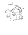
- FIG. 3 is a side view of the forceps raising base shown in FIG.
- a shaft hole 12 a that fits the rotating shaft 13 is formed on the side surface of the forceps raising base 12.
- the shaft hole 12 a is formed with a flat surface portion 12 aa extending in a direction orthogonal to the axial direction (axis A) of the rotary shaft 13.
- the forceps raising base 12 is formed with a screw hole 12b communicating with the shaft hole 12a.
- a fitting groove 13 f into which the rotary shaft seal 17 is fitted is formed on the outer periphery of the rotary shaft 13.
- the forceps raising base 12 is made of a hard material such as metal, alloy, or ceramic.
- FIG. 4 is a perspective view of the rotating shaft shown in FIG.
- the rotating shaft 13 is formed with a flat surface portion 13a that extends in a direction orthogonal to the axial direction (axis A) of the rotating shaft 13 and faces the flat surface portion 12aa of the shaft hole 12a.
- the flat portion 13a is formed with a groove 13b where a tip of a screw screwed into the screw hole 12b is located.
- a flat surface portion 13c extending in the direction orthogonal to the axial direction (axis A) is formed on the outer periphery of the rotating shaft 13 on the side opposite to the forceps raising base 12.
- a pin hole 13d into which the spring pin 20 is inserted is formed inside the flat portion 13c.
- a through hole 13 e for confirming water tightness between the forceps raising base 12 and the rotary shaft 13 is formed inside the rotary shaft 13. Specifically, when the gas is introduced from the side opposite to the forceps raising base 12 of the through hole 13e in a state where the portion where the forceps raising base 12 and the forceps base seal 19 are in contact with each other is immersed in the liquid, The watertightness between the forceps raising base 12 and the rotating shaft 13 can be confirmed by whether or not it leaks.
- the rotating shaft 13 is made of, for example, a metal or an alloy.
- the surface of the rotating shaft 13 is preferably coated with good slidability.
- the surface of the rotary shaft 13 is coated with DLC (Diamond-Like Carbon), fluorine, plating, or the like.
- DLC Diamond-Like Carbon
- fluorine fluorine
- plating or the like.
- the rotary shaft 13 slides with respect to the rotary shaft seal 17, but when the housing 15 slides with respect to the rotary shaft seal 17, these are placed on the surface of the housing 15.
- a coating is preferably applied.
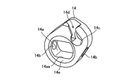
- FIG. 5 is a perspective view of the arm portion shown in FIG.
- the arm portion 14 is formed with a through hole 14 a through which the rotation shaft 13 is inserted.
- the through hole 14 a extends in a direction orthogonal to the axial direction (axis A), and has a flat surface portion 14 aa facing the flat surface portion 13 c of the rotating shaft 13.
- the through-hole 14a and the rotating shaft 13 are fitted in the state where the flat surface portion 14aa of the through-hole 14a and the flat surface portion 13c of the rotating shaft 13 face each other.
- the arm portion 14 is formed with a pin hole 14b into which the spring pin 20 is inserted.
- the through-hole 14a and the rotating shaft 13 fit, and the rotating shaft 13 and the arm part 14 can be rotated integrally by inserting the spring pin 20 in the pin hole 13d and the pin hole 14b.
- the arm portion 14 is formed with a wire engaging portion 14 c that engages with a cylindrical wire tip portion formed at the tip of the forceps operation wire 16.
- the arm portion 14 is formed with a slit 14d for inserting the wire tip portion into the wire engaging portion 14c so as to be connected to the wire engaging portion 14c.
- the slit 14d is formed at a position where the distal end of the wire can be inserted from above in FIG.
- a stepped portion 14e is formed on the outer periphery of the through hole 14a on both side surfaces of the arm portion 14 (see FIGS. 2 and 5). The formation of the stepped portion 14e prevents the arm portion 14 from being displaced in the axial direction (axis A) with respect to the housing 15.
- the forceps raising base 12 is prevented from moving in the axial direction (axis A), and the forceps raising base 12 can be accurately raised directly above.
- the clearance between the wall surface of the distal end hard portion 11 and the forceps raising base 12 can be kept constant, thereby ensuring cleaning.
- the stepped portion 14e is formed, the area where the arm portion 14 and the housing 15 are in contact with each other is reduced, and the frictional resistance between the arm portion 14 and the housing 15 can be reduced.
- the arm part 14 consists of a metal or an alloy, for example.
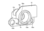
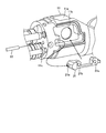
- FIG. 6 is a perspective view of the housing shown in FIG.
- the housing 15 includes, in the axial direction (axis A), the first bearing portion 15 a positioned on the forceps raising base 12 side from the arm portion 14 in the axial direction (axis A) of the rotary shaft 13.
- a second bearing portion 15b located on the opposite side of the arm portion 14 from the first bearing portion 15a.
- the housing 15 is made of, for example, metal or alloy, and the first bearing portion 15a and the second bearing portion 15b are integrally formed.
- a first shaft hole 15aa for rotatably supporting the rotary shaft 13 is formed in the first bearing portion 15a.
- a second shaft hole 15ba that is coaxial with the first shaft hole 15aa that rotatably supports the rotary shaft 13 is formed in the second bearing portion 15b.
- the second bearing portion 15b is formed with a screw hole 15bb and a screw hole 15bc that are used when the housing 15 is fixed to the distal end hard portion 11.
- the forceps operation wire 16 extends to the proximal end side, moves in the insertion direction in accordance with an operation on the operation unit 3, and moves through the arm unit 14 and the rotation shaft 13 to move the forceps raising base 12. Rotate.
- the rotary shaft seal 17 is disposed between the fitting groove 13f located on the outer periphery of the rotary shaft 13 and the inner periphery of the first shaft hole 15aa of the first bearing portion 15a.
- the rotary shaft seal 17 is made of an elastic material such as rubber or silicone.
- the housing seal 18 is disposed between the groove 15ab formed in the first bearing portion 15a and the distal end hard portion 11.
- the housing seal 18 is made of an elastic material such as rubber or silicone.
- the forceps table seal 19 is disposed between the groove 13 g formed on the outer periphery of the rotating shaft 13 and the forceps raising table 12.
- the forceps table seal 19 is made of an elastic material such as rubber or silicone.
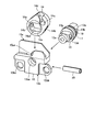
- FIG. 7 are views for explaining an endoscope assembling method.
- the arm portion 14 is disposed between the first bearing portion 15 a and the second bearing portion 15 b of the housing 15.
- the rotating shaft 13 is connected to the through hole 14a of the arm portion 14 via the first shaft hole 15aa of the first bearing portion 15a so that the flat portion 14aa of the arm portion 14 and the flat portion 13c of the rotating shaft 13 face each other.
- the spring pin 20 is inserted into the pin hole 14 b of the arm portion 14 and the pin hole 13 d of the rotating shaft 13.
- the treatment instrument raising unit shown in FIG. 8 is assembled.
- the rotating shaft of the forceps raising base 12, the rotating shaft of the rotating shaft 13, and the shaft centers of the first shaft hole 15aa and the second shaft hole 15ba are on the same straight line. There is no.
- the base 21 is inserted into the opening 11 b of the distal end hard portion 11.
- the base 21 is made of metal or alloy, and is a base on which the treatment instrument raising unit shown in FIG. 8 is attached.
- the pin 22 is inserted into the pin hole 21 a of the base 21 through the pin hole 11 c of the distal end hard portion 11. Further, the base 21 is adhered to the distal end hard portion 11 with an adhesive or the like.
- a screw hole 21b and a screw hole 21c are formed in the base 21.
- the treatment instrument raising unit shown in FIG. 8 is inserted into the opening 11 b of the distal end hard portion 11 with the forceps raising base 12 disposed in the opening 11 a of the distal end hard portion 11.
- the outer periphery of the first shaft hole 15aa of the first bearing portion 15a is fitted into the through hole 11d of the hard tip portion 11.
- the rotating shaft 13 is inserted into the shaft hole 12 a of the forceps raising base 12.
- the screw 25 is screwed into the screw hole 21b of the base 21 through the screw hole 15bc of the second bearing portion 15b.
- the wire distal end portion 16a of the forceps operation wire 16 is assembled to the wire engaging portion 14c of the arm portion 14 through the slit 14d.
- FIG. 11 is a cross-sectional view along the axis A which is the rotation axis of the rotation shaft 13.
- the screw 23 is screwed into the screw hole 12 b of the forceps raising base 12 in a state where the rotating shaft 13 is inserted into the through hole 11 d of the distal end hard portion 11.
- the forceps raising base 12 and the rotating shaft 13 are fixed.
- the groove 12c of the forceps raising base 12 is sealed with a screw concealing member 24 coated with an adhesive.
- the cover 26 is adhered with an adhesive or the like so as to cover the step portion 11e of the distal end hard portion 11, and the screw 27 is screwed into the screw hole 21c through the hole 26a and the screw hole 15bb. Match. As a result, the space closer to the cover 26 than the rotary shaft seal 17 is kept watertight. Further, the lid 28 is bonded from above with an adhesive. As a result, the distal end portion of the endoscope 1 shown in FIG. 13 is assembled.
- the rotation shaft 13 that rotates the forceps raising base 12 is rotated. Is prevented from tilting. As a result, even if the operation for raising the forceps raising base 12 is repeatedly performed, the watertight state can be maintained and rotation failure can be prevented.
- the inclination generated by the clearance between the rotary shaft 13 and the housing 15 is opposite to the forceps raising base 12 of the second shaft hole 15ba from the end surface toward the forceps raising base 12 of the first shaft hole 15aa.
- the distance to the end face on the side is small, and the amount by which the rotating shaft 13 tilts is small. As a result, the effect of maintaining the watertight state and preventing the occurrence of rotation failure is high.
- FIG. 14 is a diagram illustrating a partial configuration of the distal end portion of the endoscope according to the first modification of the embodiment.
- a screw hole 13Ad is formed in the rotating shaft 13A, and a screw hole 14Ab is formed in the arm portion 14A.
- the pin screw 20A is screwed into the screw hole 13Ad and the screw hole 14Ab.
- a screw may be used instead of the spring pin.
- the recessed part for confirming the watertightness between forceps raising base and the rotating shaft 13A is formed in the center part of the longitudinal direction of the pin screw 20A.
- FIG. 15 is a diagram illustrating a partial configuration of the distal end portion of the endoscope according to the second modification of the embodiment.
- the rotary shaft 13B is press-fitted into the through hole 14Ba of the arm portion 14B.
- the fixing method of an arm part and a rotating shaft is not specifically limited.
- the method for fixing the rotating shaft and the forceps raising base is not particularly limited.
- the hard tip portion 11 may be made of a metal or an alloy.
- the housing 15 may be directly fixed to the distal end hard portion 11 with screws or the like without providing the base 21.
Landscapes
- Health & Medical Sciences (AREA)
- Life Sciences & Earth Sciences (AREA)
- Surgery (AREA)
- Physics & Mathematics (AREA)
- Engineering & Computer Science (AREA)
- Heart & Thoracic Surgery (AREA)
- Molecular Biology (AREA)
- Optics & Photonics (AREA)
- Pathology (AREA)
- Radiology & Medical Imaging (AREA)
- Biophysics (AREA)
- Biomedical Technology (AREA)
- Veterinary Medicine (AREA)
- Medical Informatics (AREA)
- Nuclear Medicine, Radiotherapy & Molecular Imaging (AREA)
- Animal Behavior & Ethology (AREA)
- General Health & Medical Sciences (AREA)
- Public Health (AREA)
- Signal Processing (AREA)
- Manufacturing & Machinery (AREA)
- Astronomy & Astrophysics (AREA)
- General Physics & Mathematics (AREA)
- Endoscopes (AREA)
- Instruments For Viewing The Inside Of Hollow Bodies (AREA)
- Ultra Sonic Daignosis Equipment (AREA)
Priority Applications (1)
| Application Number | Priority Date | Filing Date | Title |
|---|---|---|---|
| US16/983,287 US11805987B2 (en) | 2018-02-05 | 2020-08-03 | Endoscope having distal-end rigid portion with rotatable raising base |
Applications Claiming Priority (2)
| Application Number | Priority Date | Filing Date | Title |
|---|---|---|---|
| JP2018018463A JP7022610B2 (ja) | 2018-02-05 | 2018-02-05 | 内視鏡 |
| JP2018-018463 | 2018-02-05 |
Related Child Applications (1)
| Application Number | Title | Priority Date | Filing Date |
|---|---|---|---|
| US16/983,287 Continuation US11805987B2 (en) | 2018-02-05 | 2020-08-03 | Endoscope having distal-end rigid portion with rotatable raising base |
Publications (1)
| Publication Number | Publication Date |
|---|---|
| WO2019150753A1 true WO2019150753A1 (ja) | 2019-08-08 |
Family
ID=67479634
Family Applications (1)
| Application Number | Title | Priority Date | Filing Date |
|---|---|---|---|
| PCT/JP2018/044576 Ceased WO2019150753A1 (ja) | 2018-02-05 | 2018-12-04 | 内視鏡 |
Country Status (3)
| Country | Link |
|---|---|
| US (1) | US11805987B2 (enExample) |
| JP (1) | JP7022610B2 (enExample) |
| WO (1) | WO2019150753A1 (enExample) |
Families Citing this family (7)
| Publication number | Priority date | Publication date | Assignee | Title |
|---|---|---|---|---|
| CN109068947B (zh) * | 2016-04-12 | 2021-03-12 | 奥林巴斯株式会社 | 内窥镜 |
| CN110325098A (zh) | 2016-11-28 | 2019-10-11 | 适内有限责任公司 | 具有可分离一次性轴的内窥镜 |
| USD1018844S1 (en) | 2020-01-09 | 2024-03-19 | Adaptivendo Llc | Endoscope handle |
| USD1051380S1 (en) | 2020-11-17 | 2024-11-12 | Adaptivendo Llc | Endoscope handle |
| USD1031035S1 (en) | 2021-04-29 | 2024-06-11 | Adaptivendo Llc | Endoscope handle |
| USD1070082S1 (en) | 2021-04-29 | 2025-04-08 | Adaptivendo Llc | Endoscope handle |
| USD1066659S1 (en) | 2021-09-24 | 2025-03-11 | Adaptivendo Llc | Endoscope handle |
Citations (3)
| Publication number | Priority date | Publication date | Assignee | Title |
|---|---|---|---|---|
| JP2017079877A (ja) * | 2015-10-23 | 2017-05-18 | 富士フイルム株式会社 | 内視鏡 |
| WO2017179293A1 (ja) * | 2016-04-12 | 2017-10-19 | オリンパス株式会社 | 内視鏡 |
| WO2018012486A1 (ja) * | 2016-07-11 | 2018-01-18 | Hoya株式会社 | 内視鏡 |
Family Cites Families (14)
| Publication number | Priority date | Publication date | Assignee | Title |
|---|---|---|---|---|
| JP4589520B2 (ja) | 2000-11-22 | 2010-12-01 | Hoya株式会社 | 内視鏡の先端部の製造方法及び内視鏡の先端部 |
| JP4896275B2 (ja) * | 2010-05-28 | 2012-03-14 | オリンパスメディカルシステムズ株式会社 | 内視鏡 |
| JP6357115B2 (ja) | 2015-01-15 | 2018-07-11 | Hoya株式会社 | 内視鏡 |
| JP6138404B2 (ja) * | 2015-06-10 | 2017-05-31 | オリンパス株式会社 | 内視鏡 |
| EP3345529B1 (en) * | 2015-09-02 | 2019-12-18 | FUJIFILM Corporation | Endoscope and treatment tool erecting mechanism |
| JP6495801B2 (ja) * | 2015-10-23 | 2019-04-03 | 富士フイルム株式会社 | 内視鏡 |
| WO2018016484A1 (ja) * | 2016-07-19 | 2018-01-25 | Hoya株式会社 | 内視鏡用キャップ、内視鏡および内視鏡用キャップの製造方法 |
| WO2018079792A1 (ja) * | 2016-10-28 | 2018-05-03 | オリンパス株式会社 | 内視鏡 |
| JP6865675B2 (ja) * | 2017-12-27 | 2021-04-28 | Hoya株式会社 | 起上台および内視鏡 |
| JP6848098B2 (ja) * | 2018-01-31 | 2021-03-24 | オリンパス株式会社 | 挿入装置、挿入装置の先端部材および蓋部材 |
| WO2020054372A1 (ja) * | 2018-09-10 | 2020-03-19 | 富士フイルム株式会社 | 内視鏡 |
| JP7076568B2 (ja) * | 2018-09-10 | 2022-05-27 | 富士フイルム株式会社 | 内視鏡 |
| WO2021152659A1 (ja) * | 2020-01-27 | 2021-08-05 | オリンパス株式会社 | 内視鏡 |
| JP7652637B2 (ja) * | 2021-06-16 | 2025-03-27 | 富士フイルム株式会社 | 処置具起立機構及び超音波内視鏡 |
-
2018
- 2018-02-05 JP JP2018018463A patent/JP7022610B2/ja active Active
- 2018-12-04 WO PCT/JP2018/044576 patent/WO2019150753A1/ja not_active Ceased
-
2020
- 2020-08-03 US US16/983,287 patent/US11805987B2/en active Active
Patent Citations (3)
| Publication number | Priority date | Publication date | Assignee | Title |
|---|---|---|---|---|
| JP2017079877A (ja) * | 2015-10-23 | 2017-05-18 | 富士フイルム株式会社 | 内視鏡 |
| WO2017179293A1 (ja) * | 2016-04-12 | 2017-10-19 | オリンパス株式会社 | 内視鏡 |
| WO2018012486A1 (ja) * | 2016-07-11 | 2018-01-18 | Hoya株式会社 | 内視鏡 |
Also Published As
| Publication number | Publication date |
|---|---|
| JP7022610B2 (ja) | 2022-02-18 |
| US20200359880A1 (en) | 2020-11-19 |
| US11805987B2 (en) | 2023-11-07 |
| JP2019134891A (ja) | 2019-08-15 |
Similar Documents
| Publication | Publication Date | Title |
|---|---|---|
| WO2019150753A1 (ja) | 内視鏡 | |
| JP5347084B1 (ja) | 内視鏡の湾曲操作装置 | |
| JP5315467B2 (ja) | 内視鏡 | |
| CN109715033B (zh) | 内窥镜装置的转动固定机构部和内窥镜装置 | |
| CN111789565B (zh) | 内窥镜 | |
| JP2019134891A5 (enExample) | ||
| JP2003334204A (ja) | 医療機器用担持装置 | |
| JPWO2018128001A1 (ja) | 内視鏡の湾曲操作機構 | |
| CN111655114B (zh) | 插入装置、插入装置的前端部件以及盖部件 | |
| JP6276490B1 (ja) | ポンプ装置 | |
| JP2007278505A (ja) | 遊びなしの等速ジョイント | |
| CN115038560B (zh) | 旋转位置检测单元 | |
| WO2016009690A1 (ja) | 内視鏡 | |
| JP6913244B2 (ja) | 挿入装置、及び、挿入装置の先端カバー | |
| JP2010160992A (ja) | 操作部品の操作軸の防水構造 | |
| KR101758600B1 (ko) | 유니버셜 타입 광케이블 홀더 및 이를 포함하는 광케이블 접속장치 | |
| JP4490697B2 (ja) | 内視鏡 | |
| JP4560446B2 (ja) | 光コネクタプラグ | |
| JPH11151202A (ja) | 内視鏡の処置具起上装置 | |
| CN111345857A (zh) | 一种带旋转通道的手柄及内窥镜 | |
| CN119606542B (zh) | 钢丝驱动装置及手术机器人 | |
| CN218738877U (zh) | 一种软式内窥镜及其柔性器械蛇骨 | |
| JP7463522B2 (ja) | 撮影装置及び内視鏡 | |
| JP2661456B2 (ja) | 内視鏡のアングル機構 | |
| WO2019150603A1 (ja) | 挿入装置 |
Legal Events
| Date | Code | Title | Description |
|---|---|---|---|
| 121 | Ep: the epo has been informed by wipo that ep was designated in this application |
Ref document number: 18903888 Country of ref document: EP Kind code of ref document: A1 |
|
| NENP | Non-entry into the national phase |
Ref country code: DE |
|
| 122 | Ep: pct application non-entry in european phase |
Ref document number: 18903888 Country of ref document: EP Kind code of ref document: A1 |