WO2019142759A1 - コネクタ - Google Patents
コネクタ Download PDFInfo
- Publication number
- WO2019142759A1 WO2019142759A1 PCT/JP2019/000848 JP2019000848W WO2019142759A1 WO 2019142759 A1 WO2019142759 A1 WO 2019142759A1 JP 2019000848 W JP2019000848 W JP 2019000848W WO 2019142759 A1 WO2019142759 A1 WO 2019142759A1
- Authority
- WO
- WIPO (PCT)
- Prior art keywords
- wire
- housing
- contact
- water blocking
- lead
- Prior art date
- Legal status (The legal status is an assumption and is not a legal conclusion. Google has not performed a legal analysis and makes no representation as to the accuracy of the status listed.)
- Ceased
Links
Images


Classifications
-
- H—ELECTRICITY
- H01—ELECTRIC ELEMENTS
- H01R—ELECTRICALLY-CONDUCTIVE CONNECTIONS; STRUCTURAL ASSOCIATIONS OF A PLURALITY OF MUTUALLY-INSULATED ELECTRICAL CONNECTING ELEMENTS; COUPLING DEVICES; CURRENT COLLECTORS
- H01R13/00—Details of coupling devices of the kinds covered by groups H01R12/70 or H01R24/00 - H01R33/00
- H01R13/46—Bases; Cases
- H01R13/52—Dustproof, splashproof, drip-proof, waterproof, or flameproof cases
- H01R13/5205—Sealing means between cable and housing, e.g. grommet
- H01R13/5208—Sealing means between cable and housing, e.g. grommet having at least two cable receiving openings
-
- H—ELECTRICITY
- H01—ELECTRIC ELEMENTS
- H01R—ELECTRICALLY-CONDUCTIVE CONNECTIONS; STRUCTURAL ASSOCIATIONS OF A PLURALITY OF MUTUALLY-INSULATED ELECTRICAL CONNECTING ELEMENTS; COUPLING DEVICES; CURRENT COLLECTORS
- H01R13/00—Details of coupling devices of the kinds covered by groups H01R12/70 or H01R24/00 - H01R33/00
- H01R13/46—Bases; Cases
- H01R13/52—Dustproof, splashproof, drip-proof, waterproof, or flameproof cases
- H01R13/5205—Sealing means between cable and housing, e.g. grommet
-
- H—ELECTRICITY
- H01—ELECTRIC ELEMENTS
- H01R—ELECTRICALLY-CONDUCTIVE CONNECTIONS; STRUCTURAL ASSOCIATIONS OF A PLURALITY OF MUTUALLY-INSULATED ELECTRICAL CONNECTING ELEMENTS; COUPLING DEVICES; CURRENT COLLECTORS
- H01R11/00—Individual connecting elements providing two or more spaced connecting locations for conductive members which are, or may be, thereby interconnected, e.g. end pieces for wires or cables supported by the wire or cable and having means for facilitating electrical connection to some other wire, terminal, or conductive member, blocks of binding posts
- H01R11/11—End pieces or tapping pieces for wires, supported by the wire and for facilitating electrical connection to some other wire, terminal or conductive member
- H01R11/12—End pieces terminating in an eye, hook, or fork
-
- H—ELECTRICITY
- H01—ELECTRIC ELEMENTS
- H01R—ELECTRICALLY-CONDUCTIVE CONNECTIONS; STRUCTURAL ASSOCIATIONS OF A PLURALITY OF MUTUALLY-INSULATED ELECTRICAL CONNECTING ELEMENTS; COUPLING DEVICES; CURRENT COLLECTORS
- H01R13/00—Details of coupling devices of the kinds covered by groups H01R12/70 or H01R24/00 - H01R33/00
- H01R13/648—Protective earth or shield arrangements on coupling devices, e.g. anti-static shielding
- H01R13/658—High frequency shielding arrangements, e.g. against EMI [Electro-Magnetic Interference] or EMP [Electro-Magnetic Pulse]
- H01R13/6581—Shield structure
-
- H—ELECTRICITY
- H01—ELECTRIC ELEMENTS
- H01R—ELECTRICALLY-CONDUCTIVE CONNECTIONS; STRUCTURAL ASSOCIATIONS OF A PLURALITY OF MUTUALLY-INSULATED ELECTRICAL CONNECTING ELEMENTS; COUPLING DEVICES; CURRENT COLLECTORS
- H01R9/00—Structural associations of a plurality of mutually-insulated electrical connecting elements, e.g. terminal strips or terminal blocks; Terminals or binding posts mounted upon a base or in a case; Bases therefor
- H01R9/11—End pieces for multiconductor cables supported by the cable and for facilitating connections to other conductive members, e.g. for liquid cooled welding cables
-
- H—ELECTRICITY
- H01—ELECTRIC ELEMENTS
- H01R—ELECTRICALLY-CONDUCTIVE CONNECTIONS; STRUCTURAL ASSOCIATIONS OF A PLURALITY OF MUTUALLY-INSULATED ELECTRICAL CONNECTING ELEMENTS; COUPLING DEVICES; CURRENT COLLECTORS
- H01R9/00—Structural associations of a plurality of mutually-insulated electrical connecting elements, e.g. terminal strips or terminal blocks; Terminals or binding posts mounted upon a base or in a case; Bases therefor
- H01R9/16—Fastening of connecting parts to base or case; Insulating connecting parts from base or case
- H01R9/18—Fastening by means of screw or nut
Definitions
- the technology disclosed herein relates to a connector.
- the waterproof connector comprises a housing, a rubber plug and a shield shell.
- the housing includes a wire insertion portion through which a wire is inserted, and a rubber plug storage portion is provided at the rear end of the wire insertion portion.
- the rubber plug is housed in the rubber plug housing portion, and the inner peripheral lip is in close contact with the outer peripheral surface of the wire over the entire circumference, and the outer peripheral lip is in close contact with the inner peripheral surface of the rubber plug housing in the entire peripheral portion.
- the cylindrical shell main body covers the outer peripheral surface of the wire insertion portion, and the wall is disposed opposite to the rear end surface of the wire insertion portion.
- the inner circumferential lip and the outer circumferential lip of the rubber plug are further compressed in the radial direction by the rear wall pressing the rubber plug from the rear and compressing it in the front-rear direction.
- the rubber plug is accommodated in the rubber plug accommodating portion of the housing, and the outer periphery of the rubber plug accommodating portion is covered with the shell body of the shield shell, so that the connector is enlarged.
- a connector includes an electric wire and an electric wire lead-out surface, and the electric wire extends rearward from the outer peripheral position of the electric wire lead-out surface.
- a shield member provided with a peripheral wall and a rear wall extending in a diameter reducing direction from a rear end of the peripheral wall, and a water blocking member provided with a housing sealing surface and a wire sealing surface intersecting each other; The rear wall brings the housing sealing surface into contact with the wire lead surface by contacting the water blocking member, and the peripheral wall of the shield member directly contacts the water blocking member with the electric wire sealing surface.
- the housing seal surface of the water blocking member is in contact with the wire lead-out surface, and the wire seal surface provided crossing the housing seal surface is in contact with the wire led out from the wire lead-out surface Water or the like can be prevented from entering the housing from the wire lead-out surface.
- the connector can be miniaturized.
- a plurality of electric wires are led out from the electric wire lead-out surface, and the water blocking member is provided with the electric wire sealing surface on the hole wall, and a plurality of through holes in which one of the plurality of electric wires is press-fitted.
- a rear wall of the shield member is disposed to collectively surround the plurality of electric wires and is disposed between an encircling contact portion contacting the periphery of the through holes and the plurality of electric wires.
- an inter-wire contact portion contacting between the through holes of
- the contact portion between the wires comes into contact with the portion between the plurality of through holes in the water blocking member, so that a gap is generated between the wire and the water blocking member by the deformation of the water blocking member. It can prevent.
- the gap between the wire and the housing permits the entry of water or the like. According to the above configuration, since the wire seal surface and the housing seal surface are provided so as to intersect with each other, it is possible to prevent water or the like from entering the housing.
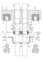
- Embodiment Embodiments are described by means of FIGS. 1 to 3.
- the connector 1 of this embodiment is a waterproof type that is attached to one end of two wires 2L and 2R that make up a harness and is connected to a device (not shown) such as an inverter.
- the connector 1 is comprised including the housing 10, the shield bracket 20 (an example of a shield member), and the water stop member 30, as shown in FIG.
- Wires 2L, 2R are disposed inside the housing 10 by insert molding, and terminal fittings 3, 3 connected to the device side are attached to one end of each of the wires 2L, 2R, and the other end is a shield It derives from the side where the bracket 20 is disposed.
- the wires 2L and 2R may be referred to as the wire 2.
- the side where the terminal fittings 3 and 3 are connected to the electric wire 2 will be described as the front, and the side where the electric wire 2 is derived from the housing 10 as the rear.
- the housing 10 includes a wire insertion portion 11 and a pair of attachment receiving portions 16 projecting laterally from the wire insertion portion 11.
- the nuts 4 are embedded in the pair of attachment receiving portions 16 in a form of being opened rearward by insert molding.
- the wire insertion portion 11 is shaped so as to protrude rearward than the attachment receiving portion 16, and the protruding portion is a wire lead-out portion 12.
- the electric wire lead-out portion 12 has an oval shape as viewed from the rear as shown in FIG.
- the wire lead-out portion 12 is formed with two wire lead-out holes 14L, 14R through which one of the wires 2L, 2R can be inserted.
- Each of the wire lead holes 14L and 14R has a circular hole shape and extends in the front and back direction in the wire insertion portion 11.
- the rear end of the wire lead-out portion 12 is a wire lead-out surface 15 in which the wire lead-out holes 14L and 14R are opened.
- the wire lead-out surface 15 is a flat surface orthogonal to the wire lead-out holes 14L and 14R.
- the electric wires 2L and 2R are respectively inserted into the electric wire lead-out holes 14L and 14R and are drawn rearward from the electric wire lead-out surface 15, as shown by imaginary lines in FIG.
- lead openings 15L and 15R the openings of the wire lead holes 14L and 14R in the wire lead surface 15 are referred to as lead openings 15L and 15R, and the lead openings 15L and 15R are collectively referred to as lead opening group 15A. Further, a peripheral region of the lead-out opening group 15A is referred to as a lead-out surrounding part 15B.
- the shield bracket 20 is a member that is formed of a metal material and covers the electric wire lead-out portion 12 of the housing 10 to shield it.
- the shield bracket 20 is comprised by the surrounding wall 25, the rear wall 22, and the attaching part 23, as shown in FIG.
- the surrounding wall 25 is a hollow cylinder having an oval shape when viewed from the rear, as shown in FIGS. 2 and 3.
- the surrounding wall 25 is longer in the front-rear dimension than the wire lead-out portion 12 and surrounds the wire lead-out portion 12 in a state where the shield bracket 20 is attached to the housing 10 as shown in FIG. It projects more backward than that.
- a portion of the surrounding wall 25 that protrudes rearward with respect to the outer peripheral position of the wire lead-out surface 15 is referred to as a peripheral wall 21.
- the front end position 21B of the circumferential wall 21 and the lead-out openings 15L and 15R of the wire lead-out surface 15 are the same in the front-rear direction as shown in FIG. 1 (B).
- the rear wall 22 is provided at the rear end of the peripheral wall 21.
- the rear wall 22 has a frame-shaped surrounding contact portion 22A extending in the diameter reducing direction from the rear end of the peripheral wall 21, and an inter-wire contact portion 22B provided along the center line in the left-right direction of the surrounding contact portion 22A. Is equipped. In other words, the surrounding contact portion 22A and the inter-wire contact portion 22B form two holding openings 24L and 24R.
- the mounting portion 23 has a shape extending leftward and rightward from the front end of the peripheral wall 21 as shown in FIG. Each mounting portion 23 is provided with mounting holes 23A one by one, penetrating through the front and back.
- the water blocking member 30 is formed of an elastically deformable synthetic resin, and as shown in FIG. 2, has an oval plate shape corresponding to the wire lead-out surface 15 as viewed from the rear.
- the plate thickness of the water blocking member 30 is slightly larger than the inner dimension of the peripheral wall 21 of the shield bracket 20 in the front-rear direction.
- the housing sealing surface 35 and the rear surface 34 provided on the front surface of the water blocking member 30 are flat surfaces.
- the water blocking member 30 is formed with a through hole group 32 consisting of two circular through holes 32L, 32R penetrating from the housing sealing surface 35 to the rear surface 34.
- the hole walls of the through holes 32L, 32R are wire seal surfaces 33L, 33R in contact with the wires 2L, 2R.
- the wire sealing surfaces 33L, 33R and the housing sealing surface 35 are orthogonal to each other.
- an area of the rear surface 34 which collectively encloses the two through holes 32L and 32R is referred to as a collective surrounding portion 34A, and a portion between the through holes 32L and the through holes 32R is an inter-electric wire It is called part 34B.
- An outer peripheral rib 31 is formed on the outer peripheral surface of the water blocking member 30 so as to protrude in the radial direction over the entire periphery.
- the outer diameter of the outer peripheral rib 31 is slightly larger than the inner diameter of the peripheral wall 21 of the shield bracket 20.
- the shield bracket 20 is attached to the housing 10 as shown in FIG. 1A by the bolts 5 being inserted into the respective mounting holes 23A and screwed into the nuts 4. ing.
- the surrounding wall 25 covers the outer peripheral surface 12A with a gap from the outer peripheral surface 12A of the wire lead-out portion 12.
- the circumferential wall 21 extends rearward beyond the wire lead-out surface 15, and the rear wall 22 is spaced from the wire lead-out surface 15 of the housing 10 at the rear end.
- a water blocking member 30 is accommodated in the gap between the wire outlet surface 15 and the rear wall 22 and is surrounded by the peripheral wall 21.
- the electric wires 2L and 2R drawn from the electric wire lead-out surface 15 extend rearward through the through holes 32L and 32R of the water blocking member 30 and the holding openings 24L and 24R of the shield bracket 20, respectively.
- the electric wire seal surface 33 of the water blocking member 30 contacts the electric wires 2L and 2R over the entire circumference, as shown in FIG. 1B, and the outer peripheral rib 31 covers the entire peripheral wall 21. I am in contact with you.
- the housing sealing surface 35 of the water blocking member 30 is in direct contact with the lead-out surrounding portion 15 B of the wire lead-out surface 15 over the entire circumference, and the rear surface 34 is in direct contact with the rear wall 22 of the shield bracket 20. More specifically, the surrounding contact portion 22A of the rear wall 22 of the shield bracket 20 directly contacts the collective surrounding portion 34A, and the inter-wire contact portion 22B directly contacts the inter-wire portion 34B. Thereby, the lead-out opening group 15A of the wire lead-out holes 14L and 14R is accommodated in the water blocking area isolated from the outer water and the like.
- the electric wires 2L and 2R derived from the wire lead-out surface 15 insert-molded in the housing 10 are press-fit into the through holes 32L and 32R of the water blocking member 30, respectively.
- the bolt 5 is inserted into the mounting hole 23A and screwed onto the nut 4 Do.
- the connector 1 of the present embodiment has the wire 2 and the wire lead-out surface 15, and the housing 10 from which the wire 2 is lead-out from the wire lead-out surface 15
- a shield member shield bracket 20
- the housing sealing surface 35 and the wire sealing surface 33 intersect each other
- the rear wall 22 of the shield member 20 contacts the water sealing member 30 to bring the housing sealing surface 35 into contact with the electric wire lead-out surface 15;
- the peripheral wall 21 of the member 20 brings the electric wire sealing surface 33 into contact with the electric wire 2 by directly contacting the water blocking member 30.
- the housing seal surface 35 of the water blocking member 30 contacts the wire lead-out surface 15, and the wire seal surface 33 provided to intersect the housing seal surface 35 is led out from the wire lead-out surface 15
- Contact with the electric wire 2 can prevent water or the like from entering the housing 10 from the electric wire lead-out surface 15.
- the connector 1 can be miniaturized.
- a plurality of electric wires 2 are led out from the electric wire lead-out surface 15, and the water blocking member 30 is provided with the electric wire sealing surface 33 in the hole wall and one of the plurality of electric wires 2 is press-fit into each
- the rear wall 22 of the shield member 20 is provided with a through hole group 32 consisting of a plurality of through holes 32L and 32R, and the surrounding contact is disposed to collectively surround the plurality of electric wires 2 and contacts the periphery of the through hole group 32 A portion 22A and an inter-wire contact portion 22B disposed between the wires 2 and in contact with the plurality of through holes 32L and 32R.
- the portion between the plurality of through holes 32L and 32R is deformed so as to escape, and between the electric wire 2 and the water blocking member 30.
- the inter-wire contact portion 22B contacts the portion between the plurality of through holes 32L and 32R of the water blocking member 30, so the electric wire 2 and the water blocking member 30 and the water blocking member 30 Can prevent the formation of gaps between the
- the electric wire 2 and the housing 10 are integrally formed by insert molding.
- the gap between the electric wire 2 and the housing 10 allows the entry of water or the like. According to the above configuration, since the wire seal surface 33 and the housing seal surface 35 are provided so as to intersect each other, it is possible to prevent water or the like from entering the housing 10.
- the number of electric wires 2L and 2R is not limited to this and may be only one or three or more. .
- the water blocking member 30 and the back wall 22 are disposed to face each other, but the water blocking member and the back wall do not necessarily have to face each other.
- another member may be disposed between the back wall and the water blocking member.
- the shield bracket 20 is fixed to the housing 10.
- the shield bracket destination is not limited thereto.
- the shield bracket 20 is fixed to the housing of the device to which the connector is attached It is also good.
- the wire 2 is disposed in the housing 10 by insert molding, but a wire insertion hole is provided in advance in the wire insertion portion, and the wire is inserted into the wire insertion hole It is also good.
- the wire lead-out portion 12 of the housing 10 is shaped so as to protrude rearward, but the shape of the wire lead-out portion is not limited thereto.
- the wire lead-out surface is flush with the rear surface of the mounting receiving portion May be provided.
- the peripheral wall of the shield member may have, for example, a planar shape extending along the rear surface of the attachment receiving portion from the outer periphery of the wire lead-out surface.
- the housing sealing surface 35 of the water blocking member 30 is a flat surface
- the housing sealing surface may not necessarily be flat, for example, the front so as to collectively surround the through holes.
- the housing sealing surface may be provided with an abutting rib projecting on the housing sealing surface. In this case, the contact pressure can be obtained more reliably by contacting the contact rib with the wire lead-out surface, and the water blocking ability can be improved.
- connector 2 electric wire 10: housing 15: electric wire lead-out surface 20: shield bracket (shield member) 21: peripheral wall 22: back wall 22A: surrounding contact portion 22B: inter-wire contact portion 30: water blocking member 32: through hole group 32L, 32R: through hole 33: wire seal surface 35: housing seal surface
Landscapes
- Connector Housings Or Holding Contact Members (AREA)
- Details Of Connecting Devices For Male And Female Coupling (AREA)
Priority Applications (2)
| Application Number | Priority Date | Filing Date | Title |
|---|---|---|---|
| CN201980007354.XA CN111542972B (zh) | 2018-01-16 | 2019-01-15 | 连接器 |
| US16/959,271 US20200335901A1 (en) | 2018-01-16 | 2019-01-15 | Connector |
Applications Claiming Priority (2)
| Application Number | Priority Date | Filing Date | Title |
|---|---|---|---|
| JP2018004904A JP6915552B2 (ja) | 2018-01-16 | 2018-01-16 | コネクタ |
| JP2018-004904 | 2018-12-17 |
Publications (1)
| Publication Number | Publication Date |
|---|---|
| WO2019142759A1 true WO2019142759A1 (ja) | 2019-07-25 |
Family
ID=67301757
Family Applications (1)
| Application Number | Title | Priority Date | Filing Date |
|---|---|---|---|
| PCT/JP2019/000848 Ceased WO2019142759A1 (ja) | 2018-01-16 | 2019-01-15 | コネクタ |
Country Status (4)
| Country | Link |
|---|---|
| US (1) | US20200335901A1 (https=) |
| JP (1) | JP6915552B2 (https=) |
| CN (1) | CN111542972B (https=) |
| WO (1) | WO2019142759A1 (https=) |
Families Citing this family (1)
| Publication number | Priority date | Publication date | Assignee | Title |
|---|---|---|---|---|
| JP6826519B2 (ja) * | 2017-11-16 | 2021-02-03 | 東海興業株式会社 | 組み立て体 |
Citations (5)
| Publication number | Priority date | Publication date | Assignee | Title |
|---|---|---|---|---|
| JP2012199051A (ja) * | 2011-03-22 | 2012-10-18 | Yazaki Corp | シールドコネクタ |
| JP2014029780A (ja) * | 2012-07-31 | 2014-02-13 | Yazaki Corp | シールドコネクタ構造 |
| JP2014146435A (ja) * | 2013-01-28 | 2014-08-14 | Yazaki Corp | コネクタ構造 |
| JP2016119186A (ja) * | 2014-12-19 | 2016-06-30 | 矢崎総業株式会社 | 防水コネクタ用ゴム栓および防水コネクタ |
| JP2017157417A (ja) * | 2016-03-02 | 2017-09-07 | 住友電装株式会社 | 防水コネクタ |
Family Cites Families (6)
| Publication number | Priority date | Publication date | Assignee | Title |
|---|---|---|---|---|
| JP2002008791A (ja) * | 2000-06-23 | 2002-01-11 | Auto Network Gijutsu Kenkyusho:Kk | シールドコネクタ及びその製造方法 |
| JP4970220B2 (ja) * | 2007-11-16 | 2012-07-04 | 矢崎総業株式会社 | シールドコネクタ |
| CN101699680B (zh) * | 2009-10-29 | 2011-07-06 | 重庆长安汽车股份有限公司 | 一种车用高压屏蔽电缆接头 |
| JP5790492B2 (ja) * | 2011-12-28 | 2015-10-07 | 住友電装株式会社 | 電線固定部材 |
| JP5952607B2 (ja) * | 2012-03-27 | 2016-07-13 | 矢崎総業株式会社 | 防水型シールドコネクタ |
| JP5700317B2 (ja) * | 2014-05-30 | 2015-04-15 | 日立金属株式会社 | 電力ハーネス |
-
2018
- 2018-01-16 JP JP2018004904A patent/JP6915552B2/ja active Active
-
2019
- 2019-01-15 US US16/959,271 patent/US20200335901A1/en not_active Abandoned
- 2019-01-15 CN CN201980007354.XA patent/CN111542972B/zh active Active
- 2019-01-15 WO PCT/JP2019/000848 patent/WO2019142759A1/ja not_active Ceased
Patent Citations (5)
| Publication number | Priority date | Publication date | Assignee | Title |
|---|---|---|---|---|
| JP2012199051A (ja) * | 2011-03-22 | 2012-10-18 | Yazaki Corp | シールドコネクタ |
| JP2014029780A (ja) * | 2012-07-31 | 2014-02-13 | Yazaki Corp | シールドコネクタ構造 |
| JP2014146435A (ja) * | 2013-01-28 | 2014-08-14 | Yazaki Corp | コネクタ構造 |
| JP2016119186A (ja) * | 2014-12-19 | 2016-06-30 | 矢崎総業株式会社 | 防水コネクタ用ゴム栓および防水コネクタ |
| JP2017157417A (ja) * | 2016-03-02 | 2017-09-07 | 住友電装株式会社 | 防水コネクタ |
Also Published As
| Publication number | Publication date |
|---|---|
| JP2019125471A (ja) | 2019-07-25 |
| CN111542972A (zh) | 2020-08-14 |
| US20200335901A1 (en) | 2020-10-22 |
| JP6915552B2 (ja) | 2021-08-04 |
| CN111542972B (zh) | 2021-08-06 |
Similar Documents
| Publication | Publication Date | Title |
|---|---|---|
| CN100388598C (zh) | 将电线连接到装置屏蔽壳的连接结构 | |
| US7618286B2 (en) | Shield connector | |
| JP5394821B2 (ja) | 防水栓、及び、該防水栓を有するコネクタ | |
| US8215988B2 (en) | Waterproof electrical connector | |
| US20140120767A1 (en) | Shield connector | |
| JP6053920B2 (ja) | コネクタの防水構造 | |
| JP2012128966A (ja) | 防水コネクタ | |
| JP6604516B2 (ja) | 防水コネクタ | |
| US20170324186A1 (en) | Electrical connector having excellent waterproof property | |
| WO2016052089A1 (ja) | シールドコネクタ | |
| CN111656622B (zh) | 连接器 | |
| JP2017157417A (ja) | 防水コネクタ | |
| JP6431471B2 (ja) | 封止部材及びコネクタ | |
| JP2010140873A (ja) | 機器用コネクタの防水構造 | |
| JP2008166105A (ja) | 防水コネクタ | |
| JP2010113862A (ja) | 防水コネクタ及びシール部材 | |
| WO2019142759A1 (ja) | コネクタ | |
| JP2012238466A (ja) | ゴム栓抜止部材の取付構造 | |
| JP3721054B2 (ja) | シールドコネクタ | |
| JP2007103044A (ja) | シールドコネクタ | |
| JP2016119186A (ja) | 防水コネクタ用ゴム栓および防水コネクタ | |
| JP6195137B1 (ja) | コネクタ | |
| JP2006004720A (ja) | 防水フラットケーブル | |
| JP2007087874A (ja) | シールドコネクタ | |
| WO2017061241A1 (ja) | 電線保持部材、および電線の保持構造 |
Legal Events
| Date | Code | Title | Description |
|---|---|---|---|
| 121 | Ep: the epo has been informed by wipo that ep was designated in this application |
Ref document number: 19740889 Country of ref document: EP Kind code of ref document: A1 |
|
| NENP | Non-entry into the national phase |
Ref country code: DE |
|
| 122 | Ep: pct application non-entry in european phase |
Ref document number: 19740889 Country of ref document: EP Kind code of ref document: A1 |