WO2019142691A1 - 使い捨て着用物品の製造方法および製造装置 - Google Patents
使い捨て着用物品の製造方法および製造装置 Download PDFInfo
- Publication number
- WO2019142691A1 WO2019142691A1 PCT/JP2019/000180 JP2019000180W WO2019142691A1 WO 2019142691 A1 WO2019142691 A1 WO 2019142691A1 JP 2019000180 W JP2019000180 W JP 2019000180W WO 2019142691 A1 WO2019142691 A1 WO 2019142691A1
- Authority
- WO
- WIPO (PCT)
- Prior art keywords
- speed
- drum
- absorbent main
- main body
- size
- Prior art date
Links
Images


Classifications
-
- B—PERFORMING OPERATIONS; TRANSPORTING
- B26—HAND CUTTING TOOLS; CUTTING; SEVERING
- B26D—CUTTING; DETAILS COMMON TO MACHINES FOR PERFORATING, PUNCHING, CUTTING-OUT, STAMPING-OUT OR SEVERING
- B26D1/00—Cutting through work characterised by the nature or movement of the cutting member or particular materials not otherwise provided for; Apparatus or machines therefor; Cutting members therefor
- B26D1/01—Cutting through work characterised by the nature or movement of the cutting member or particular materials not otherwise provided for; Apparatus or machines therefor; Cutting members therefor involving a cutting member which does not travel with the work
- B26D1/12—Cutting through work characterised by the nature or movement of the cutting member or particular materials not otherwise provided for; Apparatus or machines therefor; Cutting members therefor involving a cutting member which does not travel with the work having a cutting member moving about an axis
- B26D1/25—Cutting through work characterised by the nature or movement of the cutting member or particular materials not otherwise provided for; Apparatus or machines therefor; Cutting members therefor involving a cutting member which does not travel with the work having a cutting member moving about an axis with a non-circular cutting member
- B26D1/34—Cutting through work characterised by the nature or movement of the cutting member or particular materials not otherwise provided for; Apparatus or machines therefor; Cutting members therefor involving a cutting member which does not travel with the work having a cutting member moving about an axis with a non-circular cutting member moving about an axis parallel to the line of cut
- B26D1/40—Cutting through work characterised by the nature or movement of the cutting member or particular materials not otherwise provided for; Apparatus or machines therefor; Cutting members therefor involving a cutting member which does not travel with the work having a cutting member moving about an axis with a non-circular cutting member moving about an axis parallel to the line of cut and coacting with a rotary member
- B26D1/405—Cutting through work characterised by the nature or movement of the cutting member or particular materials not otherwise provided for; Apparatus or machines therefor; Cutting members therefor involving a cutting member which does not travel with the work having a cutting member moving about an axis with a non-circular cutting member moving about an axis parallel to the line of cut and coacting with a rotary member for thin material, e.g. for sheets, strips or the like
-
- A—HUMAN NECESSITIES
- A61—MEDICAL OR VETERINARY SCIENCE; HYGIENE
- A61F—FILTERS IMPLANTABLE INTO BLOOD VESSELS; PROSTHESES; DEVICES PROVIDING PATENCY TO, OR PREVENTING COLLAPSING OF, TUBULAR STRUCTURES OF THE BODY, e.g. STENTS; ORTHOPAEDIC, NURSING OR CONTRACEPTIVE DEVICES; FOMENTATION; TREATMENT OR PROTECTION OF EYES OR EARS; BANDAGES, DRESSINGS OR ABSORBENT PADS; FIRST-AID KITS
- A61F13/00—Bandages or dressings; Absorbent pads
- A61F13/15—Absorbent pads, e.g. sanitary towels, swabs or tampons for external or internal application to the body; Supporting or fastening means therefor; Tampon applicators
- A61F13/15577—Apparatus or processes for manufacturing
- A61F13/15585—Apparatus or processes for manufacturing of babies' napkins, e.g. diapers
-
- A—HUMAN NECESSITIES
- A61—MEDICAL OR VETERINARY SCIENCE; HYGIENE
- A61F—FILTERS IMPLANTABLE INTO BLOOD VESSELS; PROSTHESES; DEVICES PROVIDING PATENCY TO, OR PREVENTING COLLAPSING OF, TUBULAR STRUCTURES OF THE BODY, e.g. STENTS; ORTHOPAEDIC, NURSING OR CONTRACEPTIVE DEVICES; FOMENTATION; TREATMENT OR PROTECTION OF EYES OR EARS; BANDAGES, DRESSINGS OR ABSORBENT PADS; FIRST-AID KITS
- A61F13/00—Bandages or dressings; Absorbent pads
- A61F13/15—Absorbent pads, e.g. sanitary towels, swabs or tampons for external or internal application to the body; Supporting or fastening means therefor; Tampon applicators
- A61F13/15577—Apparatus or processes for manufacturing
- A61F13/15699—Forming webs by bringing together several webs, e.g. by laminating or folding several webs, with or without additional treatment of the webs
-
- A—HUMAN NECESSITIES
- A61—MEDICAL OR VETERINARY SCIENCE; HYGIENE
- A61F—FILTERS IMPLANTABLE INTO BLOOD VESSELS; PROSTHESES; DEVICES PROVIDING PATENCY TO, OR PREVENTING COLLAPSING OF, TUBULAR STRUCTURES OF THE BODY, e.g. STENTS; ORTHOPAEDIC, NURSING OR CONTRACEPTIVE DEVICES; FOMENTATION; TREATMENT OR PROTECTION OF EYES OR EARS; BANDAGES, DRESSINGS OR ABSORBENT PADS; FIRST-AID KITS
- A61F13/00—Bandages or dressings; Absorbent pads
- A61F13/15—Absorbent pads, e.g. sanitary towels, swabs or tampons for external or internal application to the body; Supporting or fastening means therefor; Tampon applicators
- A61F13/15577—Apparatus or processes for manufacturing
- A61F13/15707—Mechanical treatment, e.g. notching, twisting, compressing, shaping
- A61F13/15723—Partitioning batts; Cutting
-
- A—HUMAN NECESSITIES
- A61—MEDICAL OR VETERINARY SCIENCE; HYGIENE
- A61F—FILTERS IMPLANTABLE INTO BLOOD VESSELS; PROSTHESES; DEVICES PROVIDING PATENCY TO, OR PREVENTING COLLAPSING OF, TUBULAR STRUCTURES OF THE BODY, e.g. STENTS; ORTHOPAEDIC, NURSING OR CONTRACEPTIVE DEVICES; FOMENTATION; TREATMENT OR PROTECTION OF EYES OR EARS; BANDAGES, DRESSINGS OR ABSORBENT PADS; FIRST-AID KITS
- A61F13/00—Bandages or dressings; Absorbent pads
- A61F13/15—Absorbent pads, e.g. sanitary towels, swabs or tampons for external or internal application to the body; Supporting or fastening means therefor; Tampon applicators
- A61F13/15577—Apparatus or processes for manufacturing
- A61F13/15707—Mechanical treatment, e.g. notching, twisting, compressing, shaping
- A61F13/15739—Sealing, e.g. involving cutting
-
- A—HUMAN NECESSITIES
- A61—MEDICAL OR VETERINARY SCIENCE; HYGIENE
- A61F—FILTERS IMPLANTABLE INTO BLOOD VESSELS; PROSTHESES; DEVICES PROVIDING PATENCY TO, OR PREVENTING COLLAPSING OF, TUBULAR STRUCTURES OF THE BODY, e.g. STENTS; ORTHOPAEDIC, NURSING OR CONTRACEPTIVE DEVICES; FOMENTATION; TREATMENT OR PROTECTION OF EYES OR EARS; BANDAGES, DRESSINGS OR ABSORBENT PADS; FIRST-AID KITS
- A61F13/00—Bandages or dressings; Absorbent pads
- A61F13/15—Absorbent pads, e.g. sanitary towels, swabs or tampons for external or internal application to the body; Supporting or fastening means therefor; Tampon applicators
- A61F13/15577—Apparatus or processes for manufacturing
- A61F13/15764—Transferring, feeding or handling devices; Drives
-
- A—HUMAN NECESSITIES
- A61—MEDICAL OR VETERINARY SCIENCE; HYGIENE
- A61F—FILTERS IMPLANTABLE INTO BLOOD VESSELS; PROSTHESES; DEVICES PROVIDING PATENCY TO, OR PREVENTING COLLAPSING OF, TUBULAR STRUCTURES OF THE BODY, e.g. STENTS; ORTHOPAEDIC, NURSING OR CONTRACEPTIVE DEVICES; FOMENTATION; TREATMENT OR PROTECTION OF EYES OR EARS; BANDAGES, DRESSINGS OR ABSORBENT PADS; FIRST-AID KITS
- A61F13/00—Bandages or dressings; Absorbent pads
- A61F13/15—Absorbent pads, e.g. sanitary towels, swabs or tampons for external or internal application to the body; Supporting or fastening means therefor; Tampon applicators
- A61F13/15577—Apparatus or processes for manufacturing
- A61F13/15804—Plant, e.g. involving several steps
-
- B—PERFORMING OPERATIONS; TRANSPORTING
- B26—HAND CUTTING TOOLS; CUTTING; SEVERING
- B26D—CUTTING; DETAILS COMMON TO MACHINES FOR PERFORATING, PUNCHING, CUTTING-OUT, STAMPING-OUT OR SEVERING
- B26D1/00—Cutting through work characterised by the nature or movement of the cutting member or particular materials not otherwise provided for; Apparatus or machines therefor; Cutting members therefor
- B26D1/01—Cutting through work characterised by the nature or movement of the cutting member or particular materials not otherwise provided for; Apparatus or machines therefor; Cutting members therefor involving a cutting member which does not travel with the work
- B26D1/12—Cutting through work characterised by the nature or movement of the cutting member or particular materials not otherwise provided for; Apparatus or machines therefor; Cutting members therefor involving a cutting member which does not travel with the work having a cutting member moving about an axis
- B26D1/25—Cutting through work characterised by the nature or movement of the cutting member or particular materials not otherwise provided for; Apparatus or machines therefor; Cutting members therefor involving a cutting member which does not travel with the work having a cutting member moving about an axis with a non-circular cutting member
- B26D1/34—Cutting through work characterised by the nature or movement of the cutting member or particular materials not otherwise provided for; Apparatus or machines therefor; Cutting members therefor involving a cutting member which does not travel with the work having a cutting member moving about an axis with a non-circular cutting member moving about an axis parallel to the line of cut
- B26D1/40—Cutting through work characterised by the nature or movement of the cutting member or particular materials not otherwise provided for; Apparatus or machines therefor; Cutting members therefor involving a cutting member which does not travel with the work having a cutting member moving about an axis with a non-circular cutting member moving about an axis parallel to the line of cut and coacting with a rotary member
-
- B—PERFORMING OPERATIONS; TRANSPORTING
- B26—HAND CUTTING TOOLS; CUTTING; SEVERING
- B26D—CUTTING; DETAILS COMMON TO MACHINES FOR PERFORATING, PUNCHING, CUTTING-OUT, STAMPING-OUT OR SEVERING
- B26D7/00—Details of apparatus for cutting, cutting-out, stamping-out, punching, perforating, or severing by means other than cutting
- B26D7/06—Arrangements for feeding or delivering work of other than sheet, web, or filamentary form
-
- B—PERFORMING OPERATIONS; TRANSPORTING
- B65—CONVEYING; PACKING; STORING; HANDLING THIN OR FILAMENTARY MATERIAL
- B65H—HANDLING THIN OR FILAMENTARY MATERIAL, e.g. SHEETS, WEBS, CABLES
- B65H20/00—Advancing webs
- B65H20/12—Advancing webs by suction roller
-
- B—PERFORMING OPERATIONS; TRANSPORTING
- B65—CONVEYING; PACKING; STORING; HANDLING THIN OR FILAMENTARY MATERIAL
- B65H—HANDLING THIN OR FILAMENTARY MATERIAL, e.g. SHEETS, WEBS, CABLES
- B65H35/00—Delivering articles from cutting or line-perforating machines; Article or web delivery apparatus incorporating cutting or line-perforating devices, e.g. adhesive tape dispensers
- B65H35/04—Delivering articles from cutting or line-perforating machines; Article or web delivery apparatus incorporating cutting or line-perforating devices, e.g. adhesive tape dispensers from or with transverse cutters or perforators
- B65H35/08—Delivering articles from cutting or line-perforating machines; Article or web delivery apparatus incorporating cutting or line-perforating devices, e.g. adhesive tape dispensers from or with transverse cutters or perforators from or with revolving, e.g. cylinder, cutters or perforators
-
- B—PERFORMING OPERATIONS; TRANSPORTING
- B26—HAND CUTTING TOOLS; CUTTING; SEVERING
- B26D—CUTTING; DETAILS COMMON TO MACHINES FOR PERFORATING, PUNCHING, CUTTING-OUT, STAMPING-OUT OR SEVERING
- B26D7/00—Details of apparatus for cutting, cutting-out, stamping-out, punching, perforating, or severing by means other than cutting
- B26D7/01—Means for holding or positioning work
- B26D7/018—Holding the work by suction
Definitions
- the present invention relates to a method and an apparatus for manufacturing disposable wearing articles.
- Patent Document 1 In the manufacture of a wearing article of this type, there is known a method of cutting sheet pieces from a continuous sheet by so-called cut-and-slip, expanding the cut pieces between the sheets and arranging them on a continuous web.
- Patent Documents 2 and 3 There is also known a method of widening the sheet interval by receiving the sheet with a holding pad on a rotating drum and accelerating the rotational speed of the holding pad.
- this method requires a mechanism for accelerating the holding pad.
- the anvil is provided on the holding pad in order to cut the sheet on the holding pad, the inertia becomes large and the control becomes difficult.
- an object of the present invention is to provide a method and an apparatus for manufacturing a disposable wearing article, which does not require changing of a drum accompanying changing of product size and which is easy to control.
- the manufacturing method of the present invention is a manufacturing method of a disposable wearing article in which an outer covering material is laminated on an absorbent main body, An introducing step of introducing the continuous laminated body S continuous in the transport direction and becoming the absorbent main body 20 into the anvil roll 2 at an introducing speed V1;
- the front end portion S1 of the continuous laminate S is adsorbed by the circumferential surface 2f of the anvil roll 2 rotating at a drum speed V2 larger than the introduction speed V1, and the circumferential surface 2f of the anvil roll 2 is A slip process of conveying the continuous laminated body S at the introduction speed V1 while causing the front end portion S1 of the continuous laminated body S to slip; Cutting the tip portions S1 of the continuous laminated body S one after another on the anvil roll 2 to obtain the absorbent main body 20 one after another; By conveying the absorbent main body 20 cut in the cutting step along the circumferential surface 2f of the anvil roll 2 at the drum speed V2, the absorbent main body 20 from the continuous laminated body S in
- the manufacturing apparatus of the present invention is a manufacturing apparatus of a disposable wearing article in which the covering material is stacked on the absorbent main body,
- the absorbent laminate 20 is conveyed along the circumferential surface 2f by conveying the continuous laminate S at the introduction speed V1 while causing slippage and cutting the tip portions S1 of the continuous laminate S one after another.
- An anvil roll 2 for separating the absorbent main body 20 from the continuous laminate S in the transport direction by transporting at a drum velocity V2 larger than the introduction velocity V1;
- a cutter 1 for cutting the tip end portion S1 of the continuous laminated body S on the anvil roll 2 one after another to generate the absorbent main body 20 one after another;
- the holding pads P receive the absorbent main bodies 20 one after another from the anvil roll 2 by a plurality of holding pads P and transport the absorbent main bodies 20 at a constant drum speed V2 while the holding pads P move around the normal L.
- a turn drum D which turns to change the posture of the absorbent main body 20 together with the holding pad P;
- a second transfer device 4 having a placement speed V3 and transferring the packaging material 21;
- Each absorbent main body 20 is received from the holding pad P of the turn drum D to each transmission pad 30A, 30B at the receiving position R1, and each absorbent main body 20 is transferred to the second conveying device 4 at the passing position R2.
- a speed change roller 3 disposed on the exterior material 21 to be conveyed; Equipped with
- the introduction speed V1 is set to the high speed first introduction speed V11
- the arrangement speed V3 is set to the high speed first arrangement speed V31
- the introduction speed V1 is set to a second introduction speed V12 that is lower than the first introduction speed V11
- the arrangement speed V3 is the first arrangement speed V31. Is set to the second placement speed V32, which is slower than The drum speed V2 is set to a constant speed regardless of the size.
- the wearing article N3 of the 3rd size whose length of the conveyance direction is still smaller than the wearing article of the 2nd size
- the arrangement speed V3 is set to a third arrangement speed V33, which is lower than the second arrangement speed V32.
- the introduction speed V1 and the arrangement speed V3 are each set to a speed according to the size of the wearing article,
- the drum speed V2 of the turn drum D is set to a constant speed regardless of the size.
- the inertia of the turn drum D having the plurality of holding pads P is small, and there is no need to accelerate or decelerate the drum speed V2 of the turn drum D.
- FIG. 1A is a developed view showing an example of a wearing article according to the present invention
- FIG. 1B is a plan view showing an example of a method for producing the wearing article.
- FIG. 2 is a schematic layout view showing a manufacturing apparatus of a worn article.
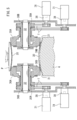
- FIG. 3A is a schematic cross-sectional view of the turn drum
- FIG. 3B is a schematic partial cross-sectional view of the same drum.
- FIG. 4A is a sectional view showing an example of the speed change roller
- FIGS. 4B to 4D are operation diagrams of the same roller.
- FIG. 5 is a cross-sectional view showing another example of the speed change roller.
- FIG. 6 is a schematic layout view showing the case of producing a second-sized worn article.
- FIG. 7 is a schematic layout view showing a case of manufacturing a third-sized worn article.
- the drum speed V2 is set to a constant speed larger than the introduction speed V1 and the arrangement speed V3 regardless of the size of the wearing article.
- the drum speed V2 is large. Therefore, the introduction speed V1 is changed according to the length in the longitudinal direction of the absorbent main body 20 in the range of a speed smaller than the drum speed V2, and the arrangement speed V3 is determined according to the length in the waist direction of the packaging material 21. Varying it would make it possible to produce wear articles of each size.
- the speed change roller 3 holds a pair of first speed change pads 30A for holding both longitudinal end portions of the preceding absorbent main body 20 of the absorbent main body 20; and the absorbent main body 20 And a pair of second shift pads 30B for holding both longitudinal ends of the subsequent absorbent main body 20. That is, one of the pair of first (second) shift pads holds one end in the longitudinal direction of the absorbent main body, and another pad of the pair of shift pads is the same absorbent main body. Hold the other end.
- the pair of shift pads 30A and 30B respectively hold the longitudinal opposite end portions of the respective absorbent main bodies 20.
- the holding pads P of the turn drum D will easily conform to the speed change pads 30A and 30B, and delivery will be smooth.
- this diaper is equipped with the absorptive main body 20 and a pair of exterior materials 21 and 21 by which this main body 20 was joined.
- the main body 20 covers a part of the front waist area, a crotch area and a part of the back waist area of the wearer when worn.
- the main body 20 is, for example, a pair of cuffs (leak preventing walls, not shown) contacting the surface of the wearer, a top sheet having liquid permeability, an absorbent core 24 for absorbing the liquid, A permeable back sheet or the like may be provided.
- the core 24 may be sandwiched between the top sheet and the back sheet.
- the absorbent main body 20 is bridged between the front waistline member 22 and the rear waistline member 22. That is, the end in the longitudinal direction (longitudinal direction) of the front portion of the absorbent main body 20 is attached to the front waistline member 22. On the other hand, the longitudinal end of the back portion of the absorbent main body 2 is attached to the rear waistline member 22.
- Each of the front and rear waistline members 22 constitutes an exterior material 21 and a continuous laminate is cut.
- Each of the waistline members 22 may be a laminate in which an elastic member and a plurality of non-woven fabrics are laminated to each other.
- the exterior material 21 may not be divided into the front and rear waist members 22, 22. It may be a so-called T-shaped diaper.
- the manufacturing apparatus includes a conveyor 5 (an example of a first conveying device), a cutter 1, an anvil roll 2, a turn drum D, a speed change roller 3 and a conveying roller 4 (an example of a second conveying device).
- a conveyor 5 an example of a first conveying device
- a cutter 1 an anvil roll 2, a turn drum D
- a speed change roller 3 an example of a second conveying device.
- the conveyor 5 conveys the continuous laminated body S at an introduction speed V1 while adsorbing a part of the continuous laminated body S continuous in the conveying direction Y (FIG. 1B) by the suction unit 50.
- the speed means the transport speed of the work (the object to be processed) and the peripheral speed of the surface of each roll or pad.
- the anvil roll 2 downstream of the conveyor 5 is rotating at a drum speed V2 greater than the introduction speed V1 of the conveyor 5.
- the anvil roll 2 sucks the front end portion S1 of the continuous laminated body S with the peripheral surface 2f while adsorbing the front end portion S1 of the continuous laminated body S with respect to the peripheral surface 2f.
- the conveyor 5 is conveyed at the introduction speed V1.
- the anvil roll 2 sucks the leading end S1 of the continuous laminated body S by the holding vacuum 2b and at the same time, has a constant speed larger than the introduction speed V1 at which the continuous laminated body S is supplied from the conveyor 5 to the anvil roll 2. It is rotating at drum speed V2.
- the leading end S1 of the continuous laminate S introduced into the anvil roll 2 at the introduction speed V1 is continuous with the continuous laminate and slips on the circumferential surface 2f of the anvil roll 2. Therefore, when the continuous laminated body S is introduced into the anvil roll 2, the speed at which the continuous laminated body S is transported on the anvil roll 2 is the introduction speed V1 of the conveyor 5.
- the cutter 1 cuts the tip portions S1 introduced onto the anvil roll 2 of the continuous laminate S continuous in the transport direction Y one after another at a predetermined interval in the transport direction Y to successively form a plurality of absorbent main bodies 20 one after another. Generate to That is, after cutting the leading end of the continuous laminate introduced onto the anvil roll 2 to generate the preceding absorbent main body 20, the leading end of the continuous laminate newly introduced onto the anvil roll 2 is cut The subsequent absorbent body 20 is produced.
- the anvil roll 2 carries out the continuous lamination by conveying the absorbent main body 20 (FIG. 1B) generated by cutting the tip portion S1 of the continuous laminated body S at the drum speed V2 along the circumferential surface 2f.
- the absorbent main body 20 is separated from the body S in the transport direction Y.
- the leading end portion S1 is released from the continuous laminated body S by cutting so that the same leading end portion S1 (absorbent main body 20) is conveyed at the drum speed V2 of the anvil roll 2,
- the distance to the tip S1 before cutting is increased.
- the distance between the continuous laminated body S conveyed on the anvil roll at the introduction speed V1 and the tip S1 after cutting conveyed at the drum speed V2 larger than the introduction speed V1 increases.
- the anvil roll 2 is provided with a holding vacuum 2b.
- the holding vacuum 2 b holds the tip portion S 1 of the continuous laminated body S before being cut by the separating cutter 1 on the anvil roll 2.
- the absorbent main body 20 obtained by cutting the tip end portion S1 with the cutter 1 is kept held by the anvil roll 2 until it is delivered to the holding pad P of the turn drum D.
- it is a well-known structure, it has a vacuum area for sucking the continuous laminate S or the absorbent main body 20 in a predetermined area of the anvil roll 2 by the holding vacuum 2b.
- the turn drum D downstream of the anvil roll 2 receives the separate absorbent main body 20 from the anvil roll 2.
- the drum speed V2 of the turn drum D and the drum speed V2 of the anvil roll 2 are set to the same speed.
- the turn drum D includes a plurality of holding pads P.
- the holding pad P receives the absorbent main body 20 from the anvil roll 2 and pivots around the normal L of the turn drum D to change the posture of the received absorbent main body 20.
- the turn drum D sequentially receives the respective absorbent main bodies 20 from the anvil roll 2 with a plurality of holding pads P. Thereafter, while the turn drum D transports the absorbent main body 20 at the constant drum speed V2, the holding pad P turns 90 ° around the normal line L of the turn drum D. As a result, the posture of the absorbent main body 20 along with the holding pad P is changed by 90 °.
- the absorbent main body 20 is passed from the turn drum D to the downstream speed change roller 4 after the posture change.
- the holding pad P may be provided with a suction device (not shown).
- the suction device sucks the absorbent main body 20 by vacuum from, for example, a large number of suction holes opened in the surface of the pad.
- the turn drum D is provided with a pivoting mechanism 6 for independently pivoting the holding pads P on the turn drum D, as is well known.
- the swing mechanism 6 may be configured by, for example, a cam groove 61 and a cam follower 62 formed on the peripheral surface of the fixed drum 60 of the turn drum D.
- Each of the holding pads P is pivotally supported on the rotating drum 63 around a normal line L.
- the rotating drum 63 is rotatably supported around the fixed drum 60 about an axis DL.
- the cam groove 61 is colored in gray.
- the transport roller 4 of FIG. 2 disposed downstream of the speed change roller 3 receiving the absorbent main body 20 from the turn drum D has a disposition speed V3 and transports the exterior material 21.
- the speed change roller 3 is disposed between the conveyance roller 4 and the turn drum D.
- the speed change roller 3 receives the absorbent main body 20 from the holding pad P of the turn drum D to the speed change pad 30 (30A, 30B) at the receiving position R1. Thereafter, the shift pads 30A and 30B arrange the absorbent main body 20 at the transfer position R2 on the exterior material 21 conveyed by the conveyance roller 4.
- the transmission roller 3 receives the absorbent main body 20 from the turn drum D at the receiving position R1 where the transmission pad 30 contacts the holding pad P via the absorbent main body 20. Thereafter, at the passing position R2 where the shift pad 30 contacts the transport roller 4 via the absorbent main body 20, the shift pad 30 is a wearable article transported by the transport roller 4 (an example of the transport device). It arrange
- the longitudinal direction of the sheathing material 21 is along the transport direction Y, and the transport direction Y is continuous with each other.
- the conveyance roller 4 may be a conveyance conveyor.
- the arrangement speed V3 of the conveyance roller 4 may be set to be smaller than the drum speed V2 of the turn drum D.
- the transmission roller 3 has, for example, two (plural) transmission pads 30 and a pair of servomotors 31 connected to the respective pads 30.
- the servomotor 31 performs the transfer position from the reception position R1. In the section up to R2, the speed of each pad 30 of the transmission roller 3 may be reduced from the drum speed V2 of the turn drum D to the arrangement speed V3 of the transport roller 4.
- the main body 20 is disposed from the pad 30 of the speed change roller 3 on the exterior material 21 conveyed by the conveyance roller 4. That is, at the receiving position R1, each pad 30 of the transmission roller 3 receives the absorbent main body 20 from the turn drum D at the drum speed V2. Thereafter, each pad 30 is decelerated to the arrangement speed V3 until it is rotated to the transfer position R2. Each pad 30 arranges the main body 20 on the exterior material 21 on the conveyance roller 4 at the arrangement speed V3 at the transfer position R2. After the placement, the respective pads 30 rotate to the receiving position R1 while increasing the speed to the drum speed V2.
- the transmission roller 3 of FIG. 4A is provided with a single long support shaft 32 in the axial direction.
- a pair of shift pads 30 rotate around the support shaft 32.
- First and second bearing portions 35 and 36 are supported at each end of the support shaft 32 via bearings 34 in each of the shift pads 30.
- the pair of shift pads 30 can rotate around the support shaft 32 without being constrained to each other.
- the shift pad 30 extending along the support shaft 32 is connected to the first bearing portion 35.
- the surface of the pad 30 in the longitudinal direction may be concave toward the support shaft 32. In this case, it will be easy to follow the shape of the arc-shaped holding pad P of the turn drum D and the like. Further, as shown in FIG. 4B, the side surface of the pad 30 may be, for example, an arc shape.
- the servomotors 31 are connected to the bearings 35 via gears 38, respectively. Therefore, each pad 30 is accelerated or decelerated as the rotational speed of the servomotor 31 changes.
- a control device 39 controls the rotation of both the servomotors 31, 31.
- the control device 39 includes a storage device for storing the relationship between the phase (rotational position) of the pad 30 with respect to the reference point (for example, the receiving position R1) and the rotational speed of the servomotor 31 and the peripheral speed of the pad 30.
- the storage device in addition to the standard size (M size) described later, the relationship is stored for each L size and / or XL size.
- the pair of pads 30, 30 periodically shift as the servomotors 31 (FIG. 4A) decelerate at least once per one rotation of the pad 30, and accelerate once. That is, the velocity of the pad 30 is the same as the drum velocity V2 of the turn drum D at the receiving position R1 (FIG. 2) where the pad 30 contacts the turn drum D and in the vicinity thereof. On the other hand, the velocity of the pad 30 is the same as the arrangement velocity V3 of the transport roller 4 at the transfer position R2 (FIG. 2) where the pad 30 contacts the transport roller 4 and its vicinity.
- the arrangement speed V3 is set to a speed lower than the drum speed V2.
- the pad 30 rotates while decelerating at a speed between the drum speed V2 and the arrangement speed V3. This reduces the distance between the leading absorbent body 20 and the trailing absorbent body 20, as is known.
- the pad 30 makes one revolution from the receiving position R1 to return to the receiving position R1
- the pad 30 has the same speed as the drum speed V2 of the turn drum D near the receiving position R1 and Thereafter, the speed is reduced to a speed smaller than the drum speed V2, and when entering a section near the transfer position R2, the speed is reduced to the same speed as the arrangement speed V3 of the transport roller 4.
- the pad 30 passes the section near the passing position R2; It is accelerated to a speed greater than the arrangement speed V3 of 4. Thereafter, when it enters a section near the receiving position R1, it further accelerates to the drum speed V2 of the turn drum D.
- the pad 30 accelerated to the drum speed V2 receives the absorbent main body 20 from the turn drum D, which is also rotating at the drum speed V2, at the receiving position R1. Note that the illustration of the absorbent main body 20 is omitted in FIGS. 4B to 4D.
- the present manufacturing method includes an introduction step, a slip step, a cutting step, a separation step, a first delivery step, a posture change step, a second delivery step, a speed change step, a transfer step, and a placement step described below.
- the continuous laminated body S which becomes the absorbent main body 20 continuously in the transport direction Y (FIG. 1B) is introduced from the conveyor 5 to the anvil roll 2 at an introduction speed V1 (V11).
- V1 introduction speed
- the front end portion S1 of the continuous laminated body S is adsorbed by the holding vacuum 2b on the circumferential surface 2f of the anvil roll 2 rotated at a drum speed V2 larger than the introduction speed V1.
- the continuous laminated body S is conveyed at the introduction speed V1 while causing the end portion S1 of the continuous laminated body S to slip on the circumferential surface 2f of the anvil roll 2.
- the front end portion S1 of the continuous laminated body S introduced at the introduction speed V1 on the anvil roll 2 is successively cut by the cutter 1 to obtain the absorbent main body 20 one after another.
- the absorbent main body 20 is transported at the drum speed V2 along the circumferential surface 2f of the anvil roll 2 to transfer the absorbent main body 20 from the continuous laminate S in the transporting direction.
- the leading end portion S1 of the cut continuous laminated body S is released from the continuous laminated body S by cutting, and conveyed at the drum speed V2 larger than the introduction speed V1. Therefore, the distance between the cut tip S1 (the absorbent main body 20) and the subsequent tip S1 of the continuous laminated body S before being conveyed at the introduction speed V1 is expanded.
- the separated absorbent main bodies 20 are sequentially transferred from the anvil roll 2 to the holding pads P of the turn drum D. That is, the absorbent main body 20 conveyed at the drum speed V2 in the anvil roll 2 is passed to the holding pad P of the turn drum D which also rotates at the drum speed V2.
- each holding pad P of the turn drum D that has received the absorbent main body 20 has a constant drum speed V2 around the axis line DL (FIG. 3B) of the turn drum D.
- the respective holding pads P turn around 90 ° around the normal L of the turn drum D on the turn drum D while rotating. By the turning, the postures of the respective absorbent main bodies 20 along with the respective holding pads P are changed.
- the drum speed is transferred from the holding pads P of the turn drum D to the speed change pads 30A and 30B of the speed change roller 3 in the absorptive main body 20 whose attitude is changed at the receiving position R1.
- the speed change roller 3 shifts from the drum speed V2 to the disposition speed V3 until the delivery position R1 reaches the delivery position R2. That is, after the speed change pad 30 of the speed change roller 3 receives the absorbent main body 20 at the drum speed V2 at the receiving position R1, the arrangement is slower than the drum speed V2 until reaching the transfer position R2. Reduce to speed V3.
- the transport device 4 transports the exterior material 21 at the arrangement speed V3 (V31).
- the absorbent main body 20 is placed one after another on the packaging material 21 transported by the transport device 4 at the transfer position R2. That is, the shift pads 30 of the transmission roller 3 that has been decelerated from the drum speed V2 to the arrangement speed V3 absorb the external material 21 conveyed at the arrangement speed V3 at the transfer position R2.
- the sex main bodies 20 are arranged one after another.
- the introduction speed V1 and the arrangement speed V3 are each set to a speed according to the size of the wearing article. Further, the introduction speed V1 may be larger than the arrangement speed V3. On the other hand, the drum speed V2 of the turn drum D is set to a constant speed regardless of the size.
- the drum speed V2 is set to a constant speed larger than the introduction speed V1 and the arrangement speed V3 regardless of the size of the worn article.
- L size for example, L size
- the introduction speed V1 is set to the high speed first introduction speed V11, and the arrangement speed V3 is set to the high speed first arrangement speed V31.
- the introduction speed V1 is set to the second introduction speed V12 lower than the first introduction speed V11.
- the arrangement speed V3 is set to a second arrangement speed V32 which is lower than the first arrangement speed V31.
- the drum speed V2 is set to a constant speed regardless of the size difference.
- the pitch (interval) P1 (FIG. 1B) of the absorbent main body 20 on the turn drum D adjacent to each other in the circumferential direction regardless of the size is also It remains constant.
- the length Ly (FIG. 1B) of the absorbent body 20 in the transport direction Y also decreases.
- the distance Dy (FIG. 6) between the rear end of the preceding absorbent body 20 of the second size wear article N2 and the front end of the subsequent absorbent body 20 corresponds to that of the first size wear article N1. It becomes larger than the distance Dy.
- the pitch P1 of the absorbent main body 20 on the turn drum D remains constant. Therefore, it is necessary to make small the pitch (interval) of the absorptive main body 20 arrange
- the distance Dx between the rear end of the preceding absorbent main body 20 and the front end of the subsequent absorbent main body 20 after posture change becomes smaller (the pitch becomes smaller).
- the second conveyance device 4 is set to the second arrangement speed V32.
- the second shift pad 30 receives the absorbent main body 20 at the receiving position R1 at the drum speed V2 and has a second arrangement speed lower than the first arrangement speed V31.
- the absorbent main body 20 is disposed on the sheathing material 21 at a velocity V32. Therefore, in the production of the second size wear article, the distance Dx between the absorbent main bodies is narrower than the distance Dx between the preceding and subsequent absorbent main bodies 20 in the production of the first size wear article. It will be arranged. This makes it possible to cope with size change.
- the introduction speed V1 is set to a third introduction speed V13, which is lower than the second introduction speed V12.
- the arrangement speed V3 is set to a third arrangement speed V33, which is lower than the second arrangement speed V32.
- the drum speed V2 is set to a constant speed regardless of the size.
- the pitch (interval) P1 of the absorbent main body 20 on the turn drum D also remains constant regardless of the size.
- the length Ly (FIG. 1B) of the absorbent main body 20 in the transport direction also decreases.
- the distance Dy between the trailing end of the leading absorbent body 20 and the leading end of the trailing absorbent body 20 is further increased.
- the pitch of the absorbent body 20 on the turn drum D remains constant. Therefore, it is necessary to further reduce the pitch (interval) of the absorbent main body 20 disposed on the exterior material 21 of FIG. 7. Therefore, in the case of the production of the third size wear article of FIG. 7, the deceleration of the shift pad 30 from the receiving position R1 to the delivery position R2 is larger than in the production of the second size wear article. The distance Dx between the rear end of the later leading absorbent body 20 and the front end of the following absorbent body 20 after posture change is further reduced (the pitch is further reduced). In manufacture of the wearing article of the third size, the second conveyance device 4 is set to the third arrangement speed V33.
- the shift pad 30 receives the absorbent main body 20 at the receiving position R1 at the drum speed V2 and a third arrangement having a speed smaller than the second arrangement speed V12.
- the absorbent main body 20 is disposed on the sheathing material 21 at a velocity V33. Therefore, in the production of the third size wear article, the distance Dx between the absorbent main bodies is narrower than the distance Dx between the preceding and subsequent absorbent main bodies 20 in the production of the second size wear article. Be placed.
- the speed change roller 3 holds a pair of first speed change pads 30A holding both longitudinal ends of the absorbent main body 20, and another longitudinal end of the absorbent main body 20. And a pair of second shift pads 30B. That is, one of the pair of first (second) shift pads 30A (30B) holds one end of the absorbent main body, and the other pad of the pair of shift pads is the same absorbent main body Hold the other end of the
- each shift pad 30A, 30B may be rotated by the servomotor 31 via the gear 38 and the timing belt T, respectively.
- the transmission pad 30B may be disposed around the support shaft 32, and the transmission pad 30A may be disposed around the transmission pad 30B.
- the diameters of the pulley portions of the speed change pads 30A and 30B may be the same.
- Each pad of the pair of shift pads 30A (30B) holding the both ends of the absorbent main body 20 rotates around the support shaft 32, and the above-mentioned exterior material 21 transported to the second transport device 4 is The absorbent body 20 is placed.
- Each pad may be provided with a suction device (not shown). The suction device sucks the end of the absorbent main body 20 by vacuum from, for example, a large number of suction holes opened on the surface of each pad.
- the present invention can be used for an apparatus for manufacturing an absorbent core of a disposable wearing article.
- Speed change pad 31 Servo motor 32: Support shaft 34: Bearing 35: First bearing portion 36: Second bearing portion 38: Gear 39: Control device 4: Second conveying device (conveying roller) 5: first conveying device (conveyor) 50: suction unit 6: turning mechanism 60: fixed drum 61: cam groove 62: cam follower 63: rotating drum D: turn drum Dy: distance Dx: distance P: holding pad R1: receiving position R2: delivery position V1: introduction speed V2: drum speed V3: arrangement speed S: continuous laminated body S1: tip L: Normal DL: Axis Y: Transport direction
Landscapes
- Health & Medical Sciences (AREA)
- Engineering & Computer Science (AREA)
- Life Sciences & Earth Sciences (AREA)
- Vascular Medicine (AREA)
- General Health & Medical Sciences (AREA)
- Epidemiology (AREA)
- Biomedical Technology (AREA)
- Heart & Thoracic Surgery (AREA)
- Veterinary Medicine (AREA)
- Animal Behavior & Ethology (AREA)
- Manufacturing & Machinery (AREA)
- Public Health (AREA)
- Mechanical Engineering (AREA)
- Forests & Forestry (AREA)
- Botany (AREA)
- Absorbent Articles And Supports Therefor (AREA)
- Details Of Cutting Devices (AREA)
Abstract
第1サイズの着用物品N1を製造する際には、導入速度V1が高速の第1導入速度V11に設定され、配置速度V3が高速の第1配置速度V31に設定され、第1サイズよりも搬送方向の長さが小さい第2サイズの着用物品N2を製造する際には導入速度V1が第1導入速度V11よりも低速の第2導入速度V12に設定され、配置速度V3が第1配置速度V31よりも低速の第2配置速度V32に設定され、ドラム速度V2はサイズに拘わらず一定速度に設定される。
Description
本発明は使い捨て着用物品の製造方法および製造装置に関する。
この種の着用物品の製造においては、いわゆる、カットアンドスリップにより、連続シートからシート片を切断し、切断した各シート片同士の間隔を拡げて連続ウェブ上に配置する方法が知られている。(特許文献1)
また、シート片を回転するドラム上の保持パッドで受取り、保持パッドの回転速度を加速することで、シート片の間隔を拡げる方法も知られている(特許文献2,3)。
しかし、この方法では保持パッドを加速する機構が必要となる。また、保持パッド上でシートを切断するためにアンビルを保持パッド上に設けているため、イナーシャ(Inertia)が大きくなり、制御が困難となる。
したがって、本発明の目的は、製品サイズの変更に伴うドラムの変更が不要で、かつ、制御も容易な使い捨て着用物品の製造方法および製造装置を提供することである。
本発明の製造方法は、吸収性本体に外装材を重ねた使い捨て着用物品の製造方法であって、
搬送方向に連続し吸収性本体20となる連続積層体Sを導入速度V1でアンビルロール2に導入する導入工程と、
前記導入速度V1よりも大きいドラム速度V2で回転する前記アンビルロール2の周面2fで前記連続積層体Sの先端部S1を吸着しながら、かつ、前記アンビルロール2の前記周面2fに対し前記連続積層体Sの前記先端部S1をスリップさせながら前記連続積層体Sを前記導入速度V1で搬送するスリップ工程と、
前記アンビルロール2上において前記連続積層体Sの前記先端部S1を次々に切断して前記吸収性本体20を次々に得る切断工程と、
前記切断工程において切断された前記吸収性本体20を前記アンビルロール2の前記周面2fに沿って前記ドラム速度V2で搬送することにより前記連続積層体Sから前記吸収性本体20を前記搬送方向に離間させる離間工程と、
前記離間工程において離間された前記各吸収性本体20を前記アンビルロール2からターンドラムDの各保持パッドPに次々に受け渡す第1受け渡し工程と、
前記ターンドラムDの前記各保持パッドPが前記ターンドラムDの軸線DLのまわりに一定の前記ドラム速度V2で回転しながら、前記ターンドラムD上において前記各保持パッドPが前記ターンドラムDの法線Lのまわりに旋回して前記各保持パッドPと共に前記各吸収性本体20の姿勢を変更する姿勢変更工程と、
受取位置R1において前記各吸収性本体20を前記ターンドラムDの前記各保持パッドPから変速ローラ3の各変速パッド30A,30Bに前記ドラム速度V2で移送する第2受け渡し工程と、
前記変速ローラ3が前記受取位置R1から渡し位置R2に至るまでに前記ドラム速度V2から配置速度V3に変速する変速工程と、
外装材21を搬送装置4が前記配置速度V3で搬送する搬送工程と、
前記渡し位置R2において前記吸収性本体20を前記搬送装置4で搬送される前記外装材21に次々に配置する配置工程とを備える。
一方、本発明の製造装置は、吸収性本体に外装材を重ねた使い捨て着用物品の製造装置であって、
搬送方向に連続し吸収性本体20となる連続積層体Sを導入速度V1で搬送する第1搬送装置5と、
前記導入速度V1よりも大きいドラム速度V2で回転し、周面2fで前記連続積層体Sの先端部S1を吸着しながら、かつ、前記周面2fに対し前記連続積層体Sの先端部S1をスリップさせながら前記連続積層体Sを前記導入速度V1で搬送すると共に前記連続積層体Sの前記先端部S1が次々に切断されて生成された前記吸収性本体20を前記周面2fに沿って前記導入速度V1よりも大きい前記ドラム速度V2で搬送することにより前記連続積層体Sから前記吸収性本体20を前記搬送方向に離間させるアンビルロール2と、
前記アンビルロール2上の前記連続積層体Sの前記先端部S1を次々に切断して前記吸収性本体20を次々に生成するカッタ1と、
前記各吸収性本体20を前記アンビルロール2から複数の各保持パッドPで次々と受け取り、一定の前記ドラム速度V2で前記吸収性本体20を搬送しながら、前記保持パッドPが法線Lのまわりに旋回して前記保持パッドPと共に前記吸収性本体20の姿勢を変更するターンドラムDと、
配置速度V3を有し、外装材21を搬送する第2搬送装置4と、
受取位置R1において前記各吸収性本体20を前記ターンドラムDの前記保持パッドPから各変速パッド30A,30Bに受け取り、かつ、渡し位置R2において前記各吸収性本体20を前記第2搬送装置4で搬送される前記外装材21に配置する変速ローラ3と、
を備える。
本発明において、第1サイズの着用物品および前記第1サイズの着用物品よりも前記搬送方向の長さが小さい第2サイズの着用物品を製造する際には例えば以下のように設定される。
前記第1サイズの着用物品N1を製造する際には前記導入速度V1が高速の第1導入速度V11に設定され、前記配置速度V3が高速の第1配置速度V31に設定され、
前記第2サイズの着用物品N2を製造する際には、前記導入速度V1が前記第1導入速度V11よりも低速の第2導入速度V12に設定され、前記配置速度V3が前記第1配置速度V31よりも低速の第2配置速度V32に設定され、
前記ドラム速度V2は前記サイズに拘わらず一定速度に設定される。
前記第1サイズの着用物品N1を製造する際には前記導入速度V1が高速の第1導入速度V11に設定され、前記配置速度V3が高速の第1配置速度V31に設定され、
前記第2サイズの着用物品N2を製造する際には、前記導入速度V1が前記第1導入速度V11よりも低速の第2導入速度V12に設定され、前記配置速度V3が前記第1配置速度V31よりも低速の第2配置速度V32に設定され、
前記ドラム速度V2は前記サイズに拘わらず一定速度に設定される。
更に、前記第2サイズの着用物品よりも前記搬送方向の長さが更に小さい第3サイズの着用物品N3を製造する際には、例えば以下のように設定される。
すなわち、前記第3サイズの着用物品N3を製造する際には、
前記導入速度V1が前記第2導入速度V12よりも更に低速の第3導入速度V13に設定され、
前記ドラム速度V2は前記サイズに拘わらず一定速度に設定され、
前記配置速度V3が前記第2配置速度V32よりも更に低速の第3配置速度V33に設定される。
すなわち、前記第3サイズの着用物品N3を製造する際には、
前記導入速度V1が前記第2導入速度V12よりも更に低速の第3導入速度V13に設定され、
前記ドラム速度V2は前記サイズに拘わらず一定速度に設定され、
前記配置速度V3が前記第2配置速度V32よりも更に低速の第3配置速度V33に設定される。
このように、本発明によれば、前記導入速度V1および配置速度V3は、各々、前記着用物品のサイズに応じた速度に設定され、
前記ターンドラムDのドラム速度V2は、前記サイズに拘わらず一定速度に設定される。
前記ターンドラムDのドラム速度V2は、前記サイズに拘わらず一定速度に設定される。
そのため、複数の保持パッドPを有しているターンドラムDのイナーシャが小さい上、ターンドラムDのドラム速度V2を加減速する必要もない。
したがって、本発明によると、製造サイズの変更に伴うドラムの変更が不要で、かつ、制御も容易な使い捨て着用物品の製造方法および製造装置を提供できる。
本発明方法において更に好ましくは、前記ドラム速度V2は着用物品のサイズに拘わらず前記導入速度V1および配置速度V3よりも大きい一定速度に設定される。
この場合、ドラム速度V2が大きい。そのため、前記ドラム速度V2よりも小さい速度の範囲で前記導入速度V1を吸収性本体20の長手方向の長さに応じて変化させ、前記配置速度V3を外装材21の胴回り方向の長さに応じて変化させるだけで、各サイズの着用物品の製造が可能となるであろう。
本発明装置において、好ましくは、前記変速ローラ3は前記吸収性本体20のうちの先行の吸収性本体20の長手方向の両端部を保持する一対の第1変速パッド30Aと、前記吸収性本体20のうちの後続の吸収性本体20の長手方向の両端部を保持する一対の第2変速パッド30Bとを備える。
すなわち、一対の第1(第2)変速パッドのうちの1つのパッドで前記吸収性本体の長手方向の一端を保持し、かつ、前記一対の変速パッドうちの別のパッドで同吸収性本体の他端を保持する。
すなわち、一対の第1(第2)変速パッドのうちの1つのパッドで前記吸収性本体の長手方向の一端を保持し、かつ、前記一対の変速パッドうちの別のパッドで同吸収性本体の他端を保持する。
この場合、各一対の変速パッド30A,30Bが、それぞれ、各吸収性本体20の長手方向の両端部を保持する。そのため、ターンドラムDの保持パッドPが前記各変速パッド30A,30Bに沿い易く、受け渡しがスムースになるであろう。
1つの前記各実施態様または下記の実施例に関連して説明および/または図示した特徴は、1つまたはそれ以上の他の実施態様または他の実施例において同一または類似な形で、および/または他の実施態様または実施例の特徴と組み合わせて、または、その代わりに利用することができる。
本発明は、添付の図面を参考にした以下の好適な実施例の説明からより明瞭に理解されるであろう。しかし、実施例および図面は単なる図示および説明のためのものであり、本発明の範囲を定めるために利用されるべきものではない。本発明の範囲は請求の範囲によってのみ定まる。添付図面において、複数の図面における同一の部品番号は、同一または相当部分を示す。
以下、本発明の実施例が図面にしたがって説明される。
まず、本製造方法および装置の説明に先立って、本製造方法により製造が可能な着用物品の一例が説明される。
まず、本製造方法および装置の説明に先立って、本製造方法により製造が可能な着用物品の一例が説明される。
図1Aに示すように、本オムツは、吸収性本体20、該本体20が接合された一対の外装材21,21を備えている。
前記本体20は、着用時に着用者の前胴回り域の一部、股下域および後胴回り域の一部を覆う。
前記本体20は、着用時に着用者の前胴回り域の一部、股下域および後胴回り域の一部を覆う。
前記本体20は、たとえば、着用者の表面に接触する一対のカフ(防漏壁。図示は省略。)と、液透過性を有するトップシートと、液を吸収する吸収性コア24と、液不透過性を有するバックシートなどを備えていてもよい。前記トップシートと前記バックシートとの間にコア24が挟まれていてもよい。
図1Aの例において、吸収性本体20は前胴回り部材22と後胴回り部材22との間に架設されている。すなわち、前記吸収性本体20のフロント部の縦方向(長手方向)の端部は、前記前胴回り部材22に貼り付けられている。一方、吸収性本体2のバック部の前記縦方向の端部は、前記後胴回り部材22に貼り付けられている。
前記前後の各胴回り部材22は、外装材21を構成し連続積層体が切断されてなる。前記各胴回り部材22は、それぞれ、弾性部材および複数の不織布が互いに積層された積層体であってもよい。
なお、外装材21は前後の胴回り部材22,22に分かれていなくてもよい。いわゆるT字型のオムツであってもよい。
なお、外装材21は前後の胴回り部材22,22に分かれていなくてもよい。いわゆるT字型のオムツであってもよい。
つぎに、製造装置の一例が説明される。
図2に示すように、本製造装置は、コンベヤ5(第1搬送装置の一例)、カッタ1、アンビルロール2、ターンドラムD、変速ローラ3および搬送ローラ4(第2搬送装置の一例)を備える。
図2に示すように、本製造装置は、コンベヤ5(第1搬送装置の一例)、カッタ1、アンビルロール2、ターンドラムD、変速ローラ3および搬送ローラ4(第2搬送装置の一例)を備える。
前記コンベヤ5は搬送方向Y(図1B)に連続した連続積層体Sの一部を吸着部50で吸着しながら前記連続積層体Sを導入速度V1で搬送する。
なお、本明細書において、速度とは、ワーク(加工対象物)の搬送速度、各ロールやパッド表面の周速度を意味する。
なお、本明細書において、速度とは、ワーク(加工対象物)の搬送速度、各ロールやパッド表面の周速度を意味する。
前記コンベヤ5の下流の前記アンビルロール2は、前記コンベヤ5の導入速度V1よりも大きいドラム速度V2で回転している。前記アンビルロール2は、周面2fで前記連続積層体Sの先端部S1を吸着しながら、かつ、周面2fに対し前記連続積層体Sの先端部S1をスリップさせながら前記連続積層体Sを前記コンベヤ5の導入速度V1で搬送する。
すなわち、前記アンビルロール2は、前記連続積層体Sの先端部S1を保持バキューム2bにより吸着すると共にコンベヤ5からアンビルロール2に前記連続積層体Sが供給される前記導入速度V1よりも大きい一定のドラム速度V2で回転している。
前記導入速度V1で同アンビルロール2に導入される前記連続積層体Sの先端部S1は連続積層体に連なっているため同アンビルロール2の周面2fにおいてスリップする。そのため、前記連続積層体Sをアンビルロール2に導入する際、同アンビルロール2上において連続積層体Sが搬送される速度は前記コンベヤ5の導入速度V1となる。
前記導入速度V1で同アンビルロール2に導入される前記連続積層体Sの先端部S1は連続積層体に連なっているため同アンビルロール2の周面2fにおいてスリップする。そのため、前記連続積層体Sをアンビルロール2に導入する際、同アンビルロール2上において連続積層体Sが搬送される速度は前記コンベヤ5の導入速度V1となる。
前記カッタ1は搬送方向Yに連続する連続積層体Sのアンビルロール2上に導入された前記先端部S1を前記搬送方向Yの所定の間隔で次々に切断して複数の吸収性本体20を次々に生成する。
すなわち、アンビルロール2上に導入された連続積層体の先端部を切断して先行の吸収性本体20を生成した後、新たにアンビルロール2上に導入された連続積層体の先端部を切断して後続の吸収性本体20を生成する。
すなわち、アンビルロール2上に導入された連続積層体の先端部を切断して先行の吸収性本体20を生成した後、新たにアンビルロール2上に導入された連続積層体の先端部を切断して後続の吸収性本体20を生成する。
前記アンビルロール2は、前記連続積層体Sの先端部S1が切断されて生成された吸収性本体20(図1B)を前記周面2fに沿って前記ドラム速度V2で搬送することにより前記連続積層体Sから前記吸収性本体20を搬送方向Yに離間させる。
すなわち、図1Bに示すように、連続積層体Sから先端部S1が切断により解放されることで同先端部S1(吸収性本体20)が前記アンビルロール2のドラム速度V2で搬送され、後続の切断前の先端部S1との距離が拡がる。換言すれば、導入速度V1でアンビルロール上で搬送される前記連続積層体Sと前記導入速度V1よりも大きな前記ドラム速度V2で搬送される切断後の先端部S1との間の距離が拡がる。
図2において、前記アンビルロール2は保持バキューム2bを備える。前記保持バキューム2bは前記個分けカッタ1で切断される前の前記連続積層体Sの先端部S1を前記アンビルロール2に保持する。更に、前記先端部S1を前記カッタ1で切断して得られた前記吸収性本体20を、前記ターンドラムDの保持パッドPに渡すまでの間、前記アンビルロール2に保持し続ける。
周知の構造であるが、前記保持バキューム2bによりアンビルロール2の所定のエリアにおいて、連続積層体Sまたは吸収性本体20を吸引するバキュームエリアを有する。
周知の構造であるが、前記保持バキューム2bによりアンビルロール2の所定のエリアにおいて、連続積層体Sまたは吸収性本体20を吸引するバキュームエリアを有する。
前記アンビルロール2の下流のターンドラムDは、前記アンビルロール2から前記個分けされた吸収性本体20を受け取る。前記ターンドラムDのドラム速度V2と前記アンビルロール2のドラム速度V2とは同じ速度に設定されている。
図2に示すように、前記ターンドラムDは複数の保持パッドPを備える。この保持パッドPは、前記アンビルロール2から前記吸収性本体20を受け取り、前記ターンドラムDの法線Lのまわりに旋回することで、前記受け取った吸収性本体20の姿勢を変更する。
図2に示すように、前記ターンドラムDは複数の保持パッドPを備える。この保持パッドPは、前記アンビルロール2から前記吸収性本体20を受け取り、前記ターンドラムDの法線Lのまわりに旋回することで、前記受け取った吸収性本体20の姿勢を変更する。
すなわち、ターンドラムDは前記各吸収性本体20を前記アンビルロール2から複数の保持パッドPで次々と受け取る。その後、ターンドラムDは一定の前記ドラム速度V2で前記吸収性本体20を搬送しながら、前記保持パッドPが前記ターンドラムDの法線Lのまわりに90°旋回する。この結果、前記保持パッドPと共に前記吸収性本体20の姿勢が90°変更される。
前記吸収性本体20は、前記姿勢変更後、前記ターンドラムDから下流の変速ローラ4に渡される。
前記吸収性本体20は、前記姿勢変更後、前記ターンドラムDから下流の変速ローラ4に渡される。
前記保持パッドPは図示しない吸着装置を備えていてもよい。吸着装置は例えばパッドの表面に開孔した多数の吸引孔からバキュームにより吸収性本体20を吸着する。
図3Aおよび図3Bに示すように、前記ターンドラムDは、周知のように、前記各保持パッドPを前記ターンドラムD上において、各々、独立して旋回させる旋回機構6を備える。
前記旋回機構6は例えば、ターンドラムDの固定ドラム60の周面に形成されたカム溝61とカムフォロア62で構成されていてもよい。前記各保持パッドPは回転ドラム63に対し、法線Lのまわりに旋回自在に支持されている。
回転ドラム63は固定ドラム60の回りを軸線DLを中心に回転自在に支持されている。
なお、図2、図3A、図3B、図6および図7においてカム溝61はグレーに着色されている。
回転ドラム63は固定ドラム60の回りを軸線DLを中心に回転自在に支持されている。
なお、図2、図3A、図3B、図6および図7においてカム溝61はグレーに着色されている。
前記ターンドラムDから吸収性本体20を受け取る前記変速ローラ3よりも下流に配置された図2の前記搬送ローラ4は配置速度V3を有し、外装材21を搬送する。
前記変速ローラ3は前記搬送ローラ4と前記ターンドラムDとの間に配置されている。前記変速ローラ3は、受取位置R1において前記吸収性本体20を前記ターンドラムDの保持パッドPから変速パッド30(30A,30B)に受け取る。その後、前記変速パッド30A,30Bは渡し位置R2において前記吸収性本体20を前記搬送ローラ4で搬送される外装材21に配置する。
前記変速ローラ3は前記搬送ローラ4と前記ターンドラムDとの間に配置されている。前記変速ローラ3は、受取位置R1において前記吸収性本体20を前記ターンドラムDの保持パッドPから変速パッド30(30A,30B)に受け取る。その後、前記変速パッド30A,30Bは渡し位置R2において前記吸収性本体20を前記搬送ローラ4で搬送される外装材21に配置する。
すなわち、前記変速パッド30が前記吸収性本体20を介して保持パッドPに接する受取位置R1において、前記変速ローラ3(変速パッド30)は前記吸収性本体20を前記ターンドラムDから受け取る。
その後、変速パッド30が吸収性本体20を介して搬送ローラ4に接する渡し位置R2において、前記変速パッド30は前記吸収性本体20を搬送ローラ4(搬送装置の一例)で搬送される着用物品の外装材21に配置する。
前記外装材21は長手方向が搬送方向Yに沿っており、搬送方向Yに互いに連続している。なお、搬送ローラ4は搬送コンベヤであってもよい。
前記搬送ローラ4の配置速度V3は前記ターンドラムDのドラム速度V2よりも小さくなるように設定されていてもよい。
その後、変速パッド30が吸収性本体20を介して搬送ローラ4に接する渡し位置R2において、前記変速パッド30は前記吸収性本体20を搬送ローラ4(搬送装置の一例)で搬送される着用物品の外装材21に配置する。
前記外装材21は長手方向が搬送方向Yに沿っており、搬送方向Yに互いに連続している。なお、搬送ローラ4は搬送コンベヤであってもよい。
前記搬送ローラ4の配置速度V3は前記ターンドラムDのドラム速度V2よりも小さくなるように設定されていてもよい。
つぎに、前記変速ローラ3の詳細な構成について説明する。
図4Aに示すように、前記変速ローラ3はたとえば2個(複数)の変速パッド30と、各パッド30に連結された一対のサーボモータ31とを有する。
図2の前記変速ローラ3の下流の前記搬送ローラ4の配置速度V3が前記ターンドラムDのドラム速度V2よりも小さく設定されている場合、前記サーボモータ31は、前記受取位置R1から前記渡し位置R2までの区間において、前記変速ローラ3の各パッド30の速度を前記ターンドラムDのドラム速度V2から前記搬送ローラ4の配置速度V3に減速させてもよい。
前記渡し位置R2において、前記搬送ローラ4で搬送される前記外装材21上に前記変速ローラ3のパッド30から前記本体20が配置される。
すなわち、前記受取位置R1において、前記変速ローラ3の各パッド30は、前記ドラム速度V2で前記ターンドラムDから前記吸収性本体20を受け取る。その後、前記各パッド30は前記渡し位置R2まで回転するまでの間に前記配置速度V3まで減速する。前記各パッド30は前記渡し位置R2において、前記配置速度V3で前記本体20を前記搬送ローラ4上の前記外装材21に配置する。前記配置後、前記各パッド30は前記ドラム速度V2まで速度を上げながら前記受取位置R1まで回転する。
図4Aの前記変速ローラ3は軸方向に長い1本の支持軸32を備える。この支持軸32のまわりを例えば一対の変速パッド30が回転する。
前記各変速パッド30は前記支持軸32の各端部において、軸受34を介して第1および第2軸受部35,36が支持されている。これにより、一対の変速パッド30が支持軸32のまわりを互いに拘束されることなく回転することができる。
前記第1軸受部35には、前記支持軸32に沿って延びる前記変速パッド30が連なっている。前記パッド30の長手方向における表面は前記支持軸32に向かって凹となる形状であってもよい。この場合、前記ターンドラムDの円弧状の保持パッドP等の形状に沿い易いだろう。
また、図4Bに示すように、前記パッド30の側面は例えば円弧状であってもよい。
また、図4Bに示すように、前記パッド30の側面は例えば円弧状であってもよい。
前記各軸受部35には、それぞれ、ギヤ38を介してサーボモータ31が連結されている。したがって、前記各パッド30は前記サーボモータ31の回転速度が変化することにより、加減速される。
前記両サーボモータ31,31は制御装置39によって回転の制御がなされる。
前記制御装置39はパッド30の基準点(たとえば受取位置R1)に対する位相(回転位置)とサーボモータ31の回転速度やパッド30の周速度との関係を記憶する記憶装置を備えている。この記憶装置には、後述する標準サイズ(Mサイズ)の他にLサイズおよび/またはXLサイズごとに前記関係が記憶されている。
前記制御装置39はパッド30の基準点(たとえば受取位置R1)に対する位相(回転位置)とサーボモータ31の回転速度やパッド30の周速度との関係を記憶する記憶装置を備えている。この記憶装置には、後述する標準サイズ(Mサイズ)の他にLサイズおよび/またはXLサイズごとに前記関係が記憶されている。
つぎに、図2の搬送ローラ4の配置速度V3が前記ターンドラムDのドラム速度V2よりも小さい場合における前記一対のサーボモータ31の変速による前記パッド30の動作の一例について説明する。このサーボモータ31の動作は前記制御装置39により制御される。
図4B~図4Dに示すように、一対のパッド30,30は各サーボモータ31(図4A)がパッド30の1回転につき少なくとも1回減速し、1回加速することにより、周期変速する。
すなわち、パッド30の速度は、パッド30がターンドラムDに接する受取位置R1(図2)およびその近傍ではターンドラムDのドラム速度V2と同じ速度となる。一方、前記パッド30の速度は、パッド30が搬送ローラ4と接する渡し位置R2(図2)およびその近傍では搬送ローラ4の配置速度V3と同じ速度となる。前記配置速度V3は前記ドラム速度V2よりも遅い速度に設定されている。
前記受取位置R1から前記渡し位置R2までの間の位置においては、パッド30は前記ドラム速度V2と配置速度V3の間の速度で減速しながら回転する。これにより、周知のように、先行の吸収性本体20と後続の吸収性本体20との間の距離が縮まる。
すなわち、パッド30の速度は、パッド30がターンドラムDに接する受取位置R1(図2)およびその近傍ではターンドラムDのドラム速度V2と同じ速度となる。一方、前記パッド30の速度は、パッド30が搬送ローラ4と接する渡し位置R2(図2)およびその近傍では搬送ローラ4の配置速度V3と同じ速度となる。前記配置速度V3は前記ドラム速度V2よりも遅い速度に設定されている。
前記受取位置R1から前記渡し位置R2までの間の位置においては、パッド30は前記ドラム速度V2と配置速度V3の間の速度で減速しながら回転する。これにより、周知のように、先行の吸収性本体20と後続の吸収性本体20との間の距離が縮まる。
換言すれば、前記パッド30は前記受取位置R1から1周して再び受取位置R1まで戻るまでの間に、前記受取位置R1およびその近傍では前記ターンドラムDのドラム速度V2と同じ速度であり、その後、減速して前記ドラム速度V2よりも小さな速度となり、前記渡し位置R2の近傍の区間に入ると前記搬送ローラ4の配置速度V3と同じ速度まで減速される。
図2および図4B~図4Dに示すように、前記パッド30は渡し位置R2において吸収性本体20を前記外装材21に配置した後、前記渡し位置R2の近傍の区間を過ぎると、前記搬送ローラ4の配置速度V3よりも大きな速度に加速される。その後、受取位置R1の近傍の区間に入ると前記ターンドラムDのドラム速度V2まで更に加速する。
前記ドラム速度V2まで加速した前記パッド30は、前記受取位置R1において、同じく前記ドラム速度V2で回転している前記ターンドラムDから前記吸収性本体20を受け取る。
なお、図4B~図4Dにおいて吸収性本体20の図示は省略されている。
前記ドラム速度V2まで加速した前記パッド30は、前記受取位置R1において、同じく前記ドラム速度V2で回転している前記ターンドラムDから前記吸収性本体20を受け取る。
なお、図4B~図4Dにおいて吸収性本体20の図示は省略されている。
つぎに、本使い捨て着用物品の製造方法の一例について説明する。
まず、第1サイズの着用物品の一例としてXLサイズ(大きいサイズ)の着用物品を製造する方法について説明する。本製造方法は、以下に説明する導入工程、スリップ工程、切断工程、離間工程、第1受け渡し工程、姿勢変更工程、第2受け渡し工程、変速工程、搬送工程および配置工程を備える。
まず、第1サイズの着用物品の一例としてXLサイズ(大きいサイズ)の着用物品を製造する方法について説明する。本製造方法は、以下に説明する導入工程、スリップ工程、切断工程、離間工程、第1受け渡し工程、姿勢変更工程、第2受け渡し工程、変速工程、搬送工程および配置工程を備える。
図2において、導入工程では、搬送方向Y(図1B)に連続し吸収性本体20となる連続積層体Sを導入速度V1(V11)でコンベヤ5からアンビルロール2に導入する。
前記導入後のスリップ工程では、前記導入速度V1よりも大きいドラム速度V2で回転する前記アンビルロール2の周面2fにおいて前記連続積層体Sの先端部S1を保持バキューム2bで吸着しながら、かつ、前記アンビルロール2の周面2fに対し前記連続積層体Sの先端部S1をスリップさせながら前記連続積層体Sを前記導入速度V1で搬送する。
前記導入後のスリップ工程では、前記導入速度V1よりも大きいドラム速度V2で回転する前記アンビルロール2の周面2fにおいて前記連続積層体Sの先端部S1を保持バキューム2bで吸着しながら、かつ、前記アンビルロール2の周面2fに対し前記連続積層体Sの先端部S1をスリップさせながら前記連続積層体Sを前記導入速度V1で搬送する。
切断工程では、前記アンビルロール2上において前記導入速度V1で導入される前記連続積層体Sの先端部S1をカッタ1により次々に切断して前記吸収性本体20を次々に得る。
前記切断後の離間工程では、前記吸収性本体20を前記アンビルロール2の前記周面2fに沿って前記ドラム速度V2で搬送することにより前記連続積層体Sから前記吸収性本体20を前記搬送方向に離間させる。すなわち、切断された前記連続積層体Sの先端部S1が切断により前記連続積層体Sから解放され、前記導入速度V1よりも大きい前記ドラム速度V2で搬送される。そのため、切断された先端部S1(吸収性本体20)と前記導入速度V1で搬送される切断前の前記連続積層体Sの後続の先端部S1との間の距離が拡がる。
前記切断後の離間工程では、前記吸収性本体20を前記アンビルロール2の前記周面2fに沿って前記ドラム速度V2で搬送することにより前記連続積層体Sから前記吸収性本体20を前記搬送方向に離間させる。すなわち、切断された前記連続積層体Sの先端部S1が切断により前記連続積層体Sから解放され、前記導入速度V1よりも大きい前記ドラム速度V2で搬送される。そのため、切断された先端部S1(吸収性本体20)と前記導入速度V1で搬送される切断前の前記連続積層体Sの後続の先端部S1との間の距離が拡がる。
前記離間後の第1受け渡し工程では、前記離間された各吸収性本体20を前記アンビルロール2からターンドラムDの各保持パッドPに次々に受け渡す。すなわち、前記アンビルロール2において前記ドラム速度V2で搬送される前記吸収性本体20は、同じく前記ドラム速度V2で回転する前記ターンドラムDの前記保持パッドPに渡される。
前記第1受け渡し工程後の姿勢変更工程では、前記吸収性本体20を受け取った前記ターンドラムDの各保持パッドPが前記ターンドラムDの軸線DL(図3B)のまわりに一定の前記ドラム速度V2で回転しながら、前記ターンドラムD上において前記各保持パッドPが前記ターンドラムDの法線Lのまわりに90°旋回する。前記旋回により、前記各保持パッドPと共に前記各吸収性本体20の姿勢が変更される。
前記姿勢変更後の第2受け渡し工程では、受取位置R1において姿勢が変更された前記吸収性本体20を前記ターンドラムDの各保持パッドPから変速ローラ3の各変速パッド30A,30Bに前記ドラム速度V2で移送する。
すなわち、前記第1受け渡し工程から前記第2受け渡し工程までの間に、前記吸収性本体20を保持した前記ターンドラムの保持パッドPが前記ターンドラムDの法線Lのまわりに90°旋回し、前記吸収性本体20の姿勢が変更された後、吸収性本体20が前記受取位置R1において前記変速ローラ3のパッドに移送される。
すなわち、前記第1受け渡し工程から前記第2受け渡し工程までの間に、前記吸収性本体20を保持した前記ターンドラムの保持パッドPが前記ターンドラムDの法線Lのまわりに90°旋回し、前記吸収性本体20の姿勢が変更された後、吸収性本体20が前記受取位置R1において前記変速ローラ3のパッドに移送される。
前記第2受け渡し工程後の変速工程では、前記変速ローラ3が前記受取位置R1から渡し位置R2に至るまでに前記ドラム速度V2から配置速度V3に変速する。
すなわち、前記変速ローラ3の前記変速パッド30は受取位置R1において前記ドラム速度V2で前記吸収性本体20を受け取った後、前記渡し位置R2に至るまでの間に前記ドラム速度V2よりも遅い前記配置速度V3まで減速する。
すなわち、前記変速ローラ3の前記変速パッド30は受取位置R1において前記ドラム速度V2で前記吸収性本体20を受け取った後、前記渡し位置R2に至るまでの間に前記ドラム速度V2よりも遅い前記配置速度V3まで減速する。
一方、搬送工程では、前記外装材21を搬送装置4が前記配置速度V3(V31)で搬送する。
配置工程では、前記渡し位置R2において前記吸収性本体20が前記搬送装置4で搬送される前記外装材21に次々に配置される。
すなわち、前記ドラム速度V2から前記配置速度V3まで減速した前記変速ローラ3の前記各変速パッド30は、前記渡し位置R2において、同じく前記配置速度V3で搬送される前記外装材21に対し、前記吸収性本体20を次々に配置する。
配置工程では、前記渡し位置R2において前記吸収性本体20が前記搬送装置4で搬送される前記外装材21に次々に配置される。
すなわち、前記ドラム速度V2から前記配置速度V3まで減速した前記変速ローラ3の前記各変速パッド30は、前記渡し位置R2において、同じく前記配置速度V3で搬送される前記外装材21に対し、前記吸収性本体20を次々に配置する。
ここにおいて、前記導入速度V1および配置速度V3は、各々、前記着用物品のサイズに応じた速度に設定される。また、前記導入速度V1は前記配置速度V3よりも大きくてもよい。一方、前記ターンドラムDのドラム速度V2は、前記サイズに拘わらず一定速度に設定される。
本例の場合、前記ドラム速度V2は着用物品のサイズに拘わらず前記導入速度V1および配置速度V3よりも大きい一定速度に設定される。
つぎに、図2の第1サイズの着用物品および第1サイズの着用物品よりも前記搬送方向の長さが小さい図6の第2サイズ(たとえばLサイズ)の着用物品を製造する方法について説明する。
前記第1サイズの着用物品N1を製造する際には、前記導入速度V1が高速の第1導入速度V11に設定され、前記配置速度V3が高速の第1配置速度V31に設定される。
一方、前記第1サイズの着用物品N1よりも小さい前記第2サイズの着用物品N2を製造する際には、前記導入速度V1が前記第1導入速度V11よりも低速の第2導入速度V12に設定され、前記配置速度V3が前記第1配置速度V31よりも低速の第2配置速度V32に設定される。
前記ドラム速度V2は前記サイズの違いに拘わらず一定速度に設定される。
一方、前記第1サイズの着用物品N1よりも小さい前記第2サイズの着用物品N2を製造する際には、前記導入速度V1が前記第1導入速度V11よりも低速の第2導入速度V12に設定され、前記配置速度V3が前記第1配置速度V31よりも低速の第2配置速度V32に設定される。
前記ドラム速度V2は前記サイズの違いに拘わらず一定速度に設定される。
ここで、ドラム速度V2は着用物品のサイズに拘わらず一定速であるから、サイズに拘わらず周方向に互いに隣り合うターンドラムD上の吸収性本体20のピッチ(間隔)P1(図1B)も一定のままである。
一方、サイズが小さくなると、吸収性本体20の搬送方向Yの長さLy(図1B)も小さくなる。したがって、前記第2サイズの着用物品N2の先行の吸収性本体20の後端と後続の吸収性本体20の先端との間の距離Dy(図6)は、前記第1サイズの着用物品N1の前記距離Dyに比べ大きくなる。
一方、サイズが小さくなると、吸収性本体20の搬送方向Yの長さLy(図1B)も小さくなる。したがって、前記第2サイズの着用物品N2の先行の吸収性本体20の後端と後続の吸収性本体20の先端との間の距離Dy(図6)は、前記第1サイズの着用物品N1の前記距離Dyに比べ大きくなる。
また、サイズが小さくなったにもかかわらず、ターンドラムD上の吸収性本体20のピッチP1が一定のままである。そのため、図6の外装材21上に配置される吸収性本体20のピッチ(間隔)は小さくする必要がある。
したがって、図6の第2サイズの着用物品の製造の場合は第1サイズの着用物品の製造の場合に比べ受取位置R1から渡し位置R2に向う変速パッド30の減速度が大きく、姿勢変更後の先行の吸収性本体20の後端と姿勢変更後の後続の吸収性本体20の先端との間の距離Dxは小さくなる(前記ピッチが小さくなる)。
前記第2サイズの着用物品の製造において、前記第2搬送装置4は前記第2配置速度V32に設定されている。
すなわち、前記第2サイズの着用物品の製造の場合、前記変速パッド30が前記ドラム速度V2で吸収性本体20を前記受取位置R1で受け取り、前記第1配置速度V31よりも速度の小さい第2配置速度V32で前記吸収性本体20を前記外装材21に配置する。そのため、第2サイズの着用物品の製造では、前記第1サイズの着用物品の製造の場合における先行と後続の吸収性本体20との前記距離Dxに比べ、吸収性本体同士の前記距離Dxが狭くなって配置される。これにより、サイズ変更に対応できる。
つぎに、図6の前記第2サイズの着用物品よりも前記搬送方向の長さが更に小さい図7の第3サイズ(たとえばMサイズ)の着用物品N3を製造する方法について説明する。
前記第3サイズの着用物品N3を製造する際には、前記導入速度V1が前記第2導入速度V12よりも更に低速の第3導入速度V13に設定される。また、前記配置速度V3は前記第2配置速度V32よりも更に低速の第3配置速度V33に設定される。
一方、前記ドラム速度V2は前記サイズに拘わらず一定速度に設定される。
前記第3サイズの着用物品N3を製造する際には、前記導入速度V1が前記第2導入速度V12よりも更に低速の第3導入速度V13に設定される。また、前記配置速度V3は前記第2配置速度V32よりも更に低速の第3配置速度V33に設定される。
一方、前記ドラム速度V2は前記サイズに拘わらず一定速度に設定される。
ここで、ドラム速度V2は着用物品のサイズに拘わらず一定速であるから、サイズに拘わらずターンドラムD上の吸収性本体20のピッチ(間隔)P1も一定のままである。
一方、サイズが更に小さくなると、吸収性本体20の搬送方向の長さLy(図1B)も更に小さくなる。したがって、先行の吸収性本体20の後端と後続の吸収性本体20の先端との間の距離Dyは更に大きくなる。
一方、サイズが更に小さくなると、吸収性本体20の搬送方向の長さLy(図1B)も更に小さくなる。したがって、先行の吸収性本体20の後端と後続の吸収性本体20の先端との間の距離Dyは更に大きくなる。
また、サイズが更に小さくなったにもかかわらず、ターンドラムD上の吸収性本体20のピッチが一定のままである。そのため、図7の外装材21上に配置される吸収性本体20のピッチ(間隔)は更に小さくする必要がある。
したがって、図7の第3サイズの着用物品の製造の場合は前記第2サイズの着用物品の製造の場合に比べ受取位置R1から渡し位置R2に向う変速パッド30の減速度が更に大きく、姿勢変更後の先行の吸収性本体20の後端と姿勢変更後の後続の吸収性本体20の先端との間の距離Dxは更に小さくなる(前記ピッチは更に小さくなる)。
前記第3サイズの着用物品の製造において、前記第2搬送装置4は前記第3配置速度V33に設定されている。
すなわち、前記第3サイズの着用物品の製造の場合、前記変速パッド30が前記ドラム速度V2で吸収性本体20を前記受取位置R1で受け取り、前記第2配置速度V12よりも速度の小さい第3配置速度V33で前記吸収性本体20を前記外装材21に配置する。そのため、第3サイズの着用物品の製造では、前記第2サイズの着用物品の製造における先行と後続の吸収性本体20との前記距離Dxに比べ、吸収性本体同士の前記距離Dxが狭くなって配置される。
つぎに、図5の変速ローラ3の他の例を説明する。
図5において、前記変速ローラ3は1つの前記吸収性本体20の長手方向の両端部を保持する一対の第1変速パッド30Aと、別の前記吸収性本体20の長手方向の両端部を保持する一対の第2変速パッド30Bとを備える。
すなわち、前記一対の第1(第2)変速パッド30A(30B)のうちの1つのパッドが前記吸収性本体の一端を保持し、前記一対の変速パッドのうちの別のパッドが同吸収性本体の他端を保持する。
図5において、前記変速ローラ3は1つの前記吸収性本体20の長手方向の両端部を保持する一対の第1変速パッド30Aと、別の前記吸収性本体20の長手方向の両端部を保持する一対の第2変速パッド30Bとを備える。
すなわち、前記一対の第1(第2)変速パッド30A(30B)のうちの1つのパッドが前記吸収性本体の一端を保持し、前記一対の変速パッドのうちの別のパッドが同吸収性本体の他端を保持する。
図5に示すように、各変速パッド30A,30Bは各々ギヤ38およびタイミングベルトTを介してサーボモータ31で回転されてもよい。
前記変速パッド30Bは支持軸32のまわりに配置され、当該変速パッド30Bのまわりに前記変速パッド30Aが配置されてもよい。前記変速パッド30Aおよび30Bのプーリ部分の径は同じであってもよい。
前記吸収性本体20の両端部を保持する一対の変速パッド30A(30B)の各パッドは支持軸32のまわりを回転し、前記第2搬送装置4に搬送されている前記外装材21上に前記吸収性本体20を配置する。
前記各パッドは図示しない吸着装置を備えていてもよい。吸着装置は例えば各パッドの表面に開孔した多数の吸引孔からバキュームにより吸収性本体20の端部を吸着する。
前記変速パッド30Bは支持軸32のまわりに配置され、当該変速パッド30Bのまわりに前記変速パッド30Aが配置されてもよい。前記変速パッド30Aおよび30Bのプーリ部分の径は同じであってもよい。
前記吸収性本体20の両端部を保持する一対の変速パッド30A(30B)の各パッドは支持軸32のまわりを回転し、前記第2搬送装置4に搬送されている前記外装材21上に前記吸収性本体20を配置する。
前記各パッドは図示しない吸着装置を備えていてもよい。吸着装置は例えば各パッドの表面に開孔した多数の吸引孔からバキュームにより吸収性本体20の端部を吸着する。
以上のとおり、図面を参照しながら好適な実施例を説明したが、当業者であれば、本明細書を見て、自明な範囲内で種々の変更および修正を容易に想定するであろう。
たとえば、前記受取位置R1から前記渡し位置R2に至る区間において、各サーボモータ31の回転速度が変化されることによって前記各変速ローラ3の変速パッド30を減速させたが、加速させてもよい。
したがって、以上のような変更および修正は、請求の範囲から定まる本発明の範囲内のものと解釈される。
たとえば、前記受取位置R1から前記渡し位置R2に至る区間において、各サーボモータ31の回転速度が変化されることによって前記各変速ローラ3の変速パッド30を減速させたが、加速させてもよい。
したがって、以上のような変更および修正は、請求の範囲から定まる本発明の範囲内のものと解釈される。
本発明は使い捨て着用物品の吸収性コアの製造装置に利用できる。
1:カッタ
2:アンビルロール 2b:保持バキューム 2f:周面
20:吸収性本体 21:外装材 22:胴回り部材 24:吸収性コア
3:変速ローラ 30:変速パッド 30A:第1変速パッド 30B:第2変速パッド 31:サーボモータ 32:支持軸 34:軸受 35:第1被軸受部 36:第2被軸受部 38:ギヤ 39:制御装置
4:第2搬送装置(搬送ローラ)
5:第1搬送装置(コンベヤ) 50:吸着部
6:旋回機構 60:固定ドラム 61:カム溝 62:カムフォロア 63:回転ドラム
D:ターンドラム Dy:距離 Dx:距離
P:保持パッド R1:受取位置 R2:渡し位置
V1:導入速度 V2:ドラム速度 V3:配置速度
S:連続積層体 S1:先端部
L:法線 DL:軸線 Y:搬送方向
Claims (9)
- 吸収性本体に外装材を重ねた使い捨て着用物品の製造方法であって、
搬送方向に連続し吸収性本体20となる連続積層体Sを導入速度V1でアンビルロール2に導入する導入工程と、
前記導入速度V1よりも大きいドラム速度V2で回転する前記アンビルロール2の周面2fで前記連続積層体Sの先端部S1を吸着しながら、かつ、前記アンビルロール2の前記周面2fに対し前記連続積層体Sの前記先端部S1をスリップさせながら前記連続積層体Sを前記導入速度V1で搬送するスリップ工程と、
前記アンビルロール2上において前記連続積層体Sの前記先端部S1を次々に切断して前記吸収性本体20を次々に得る切断工程と、
前記切断工程において切断された前記吸収性本体20を前記アンビルロール2の前記周面2fに沿って前記ドラム速度V2で搬送することにより前記連続積層体Sから前記吸収性本体20を前記搬送方向に離間させる離間工程と、
前記離間工程において離間された前記各吸収性本体20を前記アンビルロール2からターンドラムDの各保持パッドPに次々に受け渡す第1受け渡し工程と、
前記ターンドラムDの前記各保持パッドPが前記ターンドラムDの軸線DLのまわりに一定の前記ドラム速度V2で回転しながら、前記ターンドラムD上において前記各保持パッドPが前記ターンドラムDの法線Lのまわりに旋回して前記各保持パッドPと共に前記各吸収性本体20の姿勢を変更する姿勢変更工程と、
受取位置R1において前記各吸収性本体20を前記ターンドラムDの前記各保持パッドPから変速ローラ3の各変速パッド30A,30Bに前記ドラム速度V2で移送する第2受け渡し工程と、
前記変速ローラ3が前記受取位置R1から渡し位置R2に至るまでに前記ドラム速度V2から配置速度V3に変速する変速工程と、
外装材21を搬送装置4が前記配置速度V3で搬送する搬送工程と、
前記渡し位置R2において前記吸収性本体20を前記搬送装置4で搬送される前記外装材21に次々に配置する配置工程と、
を備える、物品の製造方法。 - 請求項1において、前記導入速度V1および前記配置速度V3は、各々、前記着用物品のサイズに応じた速度に設定され、
前記ターンドラムDの前記ドラム速度V2は、前記サイズに拘わらず一定速度に設定される、製造方法。 - 請求項2において、前記ドラム速度V2は着用物品のサイズに拘わらず前記導入速度V1および前記配置速度V3よりも大きい一定速度に設定される、製造方法。
- 請求項2の方法において、第1サイズの着用物品および前記第1サイズの着用物品よりも前記搬送方向の長さが小さい第2サイズの着用物品を製造する方法であって、
前記第1サイズの着用物品N1を製造する際には、前記導入速度V1が高速の第1導入速度V11に設定され、前記配置速度V3が高速の第1配置速度V31に設定され、
前記第2サイズの着用物品N2を製造する際には、前記導入速度V1が前記第1導入速度V11よりも低速の第2導入速度V12に設定され、前記配置速度V3が前記第1配置速度V31よりも低速の第2配置速度V32に設定され、
前記ドラム速度V2は前記サイズに拘わらず一定速度に設定される、着用物品の製造方法。 - 請求項4において、前記第2サイズの着用物品よりも前記搬送方向の長さが更に小さい第3サイズの着用物品N3を製造する方法であって、
前記第3サイズの着用物品N3を製造する際には、
前記導入速度V1が前記第2導入速度V12よりも更に低速の第3導入速度V13に設定され、
前記ドラム速度V2は前記サイズに拘わらず一定速度に設定され、
前記配置速度V3が前記第2配置速度V32よりも更に低速の第3配置速度V33に設定される、着用物品の製造方法。 - 請求項1~5のいずれか1項において、前記受取位置R1から前記渡し位置R2に至る区間において、各サーボモータ31の回転速度が変化されることによって前記変速ローラ3の前記各変速パッド30を減速または加速させる、製造方法。
- 吸収性本体に外装材を重ねた使い捨て着用物品の製造装置であって、
搬送方向に連続し吸収性本体20となる連続積層体Sを導入速度V1で搬送する第1搬送装置5と、
前記導入速度V1よりも大きいドラム速度V2で回転し、周面2fで前記連続積層体Sの先端部S1を吸着しながら、かつ、前記周面2fに対し前記連続積層体Sの前記先端部S1をスリップさせながら前記連続積層体Sを前記導入速度V1で搬送すると共に前記連続積層体Sの前記先端部S1が次々に切断されて生成された前記吸収性本体20を前記周面2fに沿って前記導入速度V1よりも大きい前記ドラム速度V2で搬送することにより前記連続積層体Sから前記吸収性本体20を前記搬送方向に離間させるアンビルロール2と、
前記アンビルロール2上の前記連続積層体Sの前記先端部S1を次々に切断して前記吸収性本体20を次々に生成するカッタ1と、
前記各吸収性本体20を前記アンビルロール2から複数の各保持パッドPで次々と受け取り、一定の前記ドラム速度V2で前記吸収性本体20を搬送しながら、前記保持パッドPが法線Lのまわりに旋回して前記保持パッドPと共に前記吸収性本体20の姿勢を変更するターンドラムDと、
配置速度V3を有し、外装材21を搬送する第2搬送装置4と、
受取位置R1において前記各吸収性本体20を前記ターンドラムDの前記保持パッドPから各変速パッド30A,30Bに受け取り、かつ、渡し位置R2において前記各吸収性本体20を前記第2搬送装置4で搬送される前記外装材21に配置する変速ローラ3と、
を備える、製造装置。 - 請求項7において、前記各保持パッドPを前記ターンドラムD上において、各々、独立して旋回させる旋回機構6を前記ターンドラムDが備える、製造装置。
- 請求項7もしくは8において、前記変速ローラ3は前記吸収性本体20のうちの先行の吸収性本体20の長手方向の両端部を保持する一対の第1変速パッド30Aと、前記吸収性本体20のうちの後続の吸収性本体20の長手方向の両端部を保持する一対の第2変速パッド30Bとを備える、製造装置。
Priority Applications (6)
| Application Number | Priority Date | Filing Date | Title |
|---|---|---|---|
| US16/957,126 US11311425B2 (en) | 2018-01-16 | 2019-01-08 | Manufacturing method and manufacturing apparatus for disposable wearable article |
| CN201980007221.2A CN111587100B (zh) | 2018-01-16 | 2019-01-08 | 一次性穿着物品的制造方法及制造装置 |
| EP19740760.4A EP3741337A4 (en) | 2018-01-16 | 2019-01-08 | METHOD AND DEVICE FOR MANUFACTURING A PORTABLE DISPOSABLE ITEM |
| KR1020207017736A KR102647220B1 (ko) | 2018-01-16 | 2019-01-08 | 일회용 착용 물품의 제조 방법 및 제조 장치 |
| MX2020005721A MX2020005721A (es) | 2018-01-16 | 2019-01-08 | Metodo y aparato de fabricacion para articulo usable desechable. |
| JP2019566423A JP7311432B2 (ja) | 2018-01-16 | 2019-01-08 | 使い捨て着用物品の製造方法および製造装置 |
Applications Claiming Priority (2)
| Application Number | Priority Date | Filing Date | Title |
|---|---|---|---|
| JP2018004844 | 2018-01-16 | ||
| JP2018-004844 | 2018-01-16 |
Publications (1)
| Publication Number | Publication Date |
|---|---|
| WO2019142691A1 true WO2019142691A1 (ja) | 2019-07-25 |
Family
ID=67301785
Family Applications (1)
| Application Number | Title | Priority Date | Filing Date |
|---|---|---|---|
| PCT/JP2019/000180 WO2019142691A1 (ja) | 2018-01-16 | 2019-01-08 | 使い捨て着用物品の製造方法および製造装置 |
Country Status (7)
| Country | Link |
|---|---|
| US (1) | US11311425B2 (ja) |
| EP (1) | EP3741337A4 (ja) |
| JP (1) | JP7311432B2 (ja) |
| KR (1) | KR102647220B1 (ja) |
| CN (1) | CN111587100B (ja) |
| MX (1) | MX2020005721A (ja) |
| WO (1) | WO2019142691A1 (ja) |
Cited By (1)
| Publication number | Priority date | Publication date | Assignee | Title |
|---|---|---|---|---|
| WO2023218888A1 (ja) * | 2022-05-13 | 2023-11-16 | 株式会社瑞光 | 使い捨て着用物品の製造方法および装置 |
Families Citing this family (2)
| Publication number | Priority date | Publication date | Assignee | Title |
|---|---|---|---|---|
| DE102020104275A1 (de) * | 2020-02-18 | 2021-08-19 | Bicma Hygiene Technologie Gmbh | Drehvorrichtung für eine Fertigungsanlage für Hygieneprodukte |
| CN112026260A (zh) * | 2020-09-11 | 2020-12-04 | 福建省满利红包装彩印有限公司 | 一种耐高温彩印包装袋加工设备及其加工工艺 |
Citations (7)
| Publication number | Priority date | Publication date | Assignee | Title |
|---|---|---|---|---|
| JP2003199790A (ja) * | 2001-11-02 | 2003-07-15 | Zuiko Corp | 使い捨て着用物品の製造方法 |
| WO2005075163A1 (ja) | 2004-02-05 | 2005-08-18 | Zuiko Corporation | ウエブの加工装置および加工方法 |
| JP2007260875A (ja) | 2006-03-29 | 2007-10-11 | Kao Corp | シート切断方法及び装置 |
| JP2008035872A (ja) * | 2006-08-01 | 2008-02-21 | Zuiko Corp | 使い捨て着用物品の製造方法 |
| WO2013157533A1 (ja) * | 2012-04-19 | 2013-10-24 | 株式会社瑞光 | 使い捨て着用物品の製造方法および製造装置 |
| JP2013255624A (ja) * | 2012-06-12 | 2013-12-26 | Zuiko Corp | 使い捨て着用物品の製造方法および製造装置 |
| WO2014006834A1 (ja) | 2012-07-06 | 2014-01-09 | 株式会社瑞光 | 搬送方法、使い捨て着用物品の製造方法、並びに着用物品、及び搬送装置 |
Family Cites Families (4)
| Publication number | Priority date | Publication date | Assignee | Title |
|---|---|---|---|---|
| JP4094452B2 (ja) * | 2003-02-19 | 2008-06-04 | 株式会社瑞光 | 加工装置および加工方法 |
| MX2016003541A (es) * | 2013-09-23 | 2016-06-28 | Procter & Gamble | Aparato y metodo para elaborar costuras laterales en articulos absorbentes. |
| JP6378835B2 (ja) * | 2015-05-28 | 2018-08-22 | 株式会社瑞光 | 搬送装置及びこれを用いた使い捨て着用物品の製造方法 |
| US10342711B2 (en) * | 2015-10-14 | 2019-07-09 | Unicharm Corporation | Transport method and transport device of single-cut sheet associated with absorbent article |
-
2019
- 2019-01-08 KR KR1020207017736A patent/KR102647220B1/ko active IP Right Grant
- 2019-01-08 MX MX2020005721A patent/MX2020005721A/es unknown
- 2019-01-08 US US16/957,126 patent/US11311425B2/en active Active
- 2019-01-08 CN CN201980007221.2A patent/CN111587100B/zh active Active
- 2019-01-08 EP EP19740760.4A patent/EP3741337A4/en active Pending
- 2019-01-08 WO PCT/JP2019/000180 patent/WO2019142691A1/ja unknown
- 2019-01-08 JP JP2019566423A patent/JP7311432B2/ja active Active
Patent Citations (7)
| Publication number | Priority date | Publication date | Assignee | Title |
|---|---|---|---|---|
| JP2003199790A (ja) * | 2001-11-02 | 2003-07-15 | Zuiko Corp | 使い捨て着用物品の製造方法 |
| WO2005075163A1 (ja) | 2004-02-05 | 2005-08-18 | Zuiko Corporation | ウエブの加工装置および加工方法 |
| JP2007260875A (ja) | 2006-03-29 | 2007-10-11 | Kao Corp | シート切断方法及び装置 |
| JP2008035872A (ja) * | 2006-08-01 | 2008-02-21 | Zuiko Corp | 使い捨て着用物品の製造方法 |
| WO2013157533A1 (ja) * | 2012-04-19 | 2013-10-24 | 株式会社瑞光 | 使い捨て着用物品の製造方法および製造装置 |
| JP2013255624A (ja) * | 2012-06-12 | 2013-12-26 | Zuiko Corp | 使い捨て着用物品の製造方法および製造装置 |
| WO2014006834A1 (ja) | 2012-07-06 | 2014-01-09 | 株式会社瑞光 | 搬送方法、使い捨て着用物品の製造方法、並びに着用物品、及び搬送装置 |
Non-Patent Citations (1)
| Title |
|---|
| See also references of EP3741337A4 |
Cited By (1)
| Publication number | Priority date | Publication date | Assignee | Title |
|---|---|---|---|---|
| WO2023218888A1 (ja) * | 2022-05-13 | 2023-11-16 | 株式会社瑞光 | 使い捨て着用物品の製造方法および装置 |
Also Published As
| Publication number | Publication date |
|---|---|
| MX2020005721A (es) | 2020-08-13 |
| CN111587100A (zh) | 2020-08-25 |
| JPWO2019142691A1 (ja) | 2021-01-28 |
| CN111587100B (zh) | 2022-03-18 |
| US20200345559A1 (en) | 2020-11-05 |
| JP7311432B2 (ja) | 2023-07-19 |
| EP3741337A1 (en) | 2020-11-25 |
| US11311425B2 (en) | 2022-04-26 |
| KR102647220B1 (ko) | 2024-03-14 |
| EP3741337A4 (en) | 2021-12-15 |
| KR20200110309A (ko) | 2020-09-23 |
Similar Documents
| Publication | Publication Date | Title |
|---|---|---|
| WO2019142691A1 (ja) | 使い捨て着用物品の製造方法および製造装置 | |
| EP2227205B1 (en) | A machine and a method for folding nappy/diaper blanks | |
| JP6008599B2 (ja) | 使い捨て着用物品の製造方法 | |
| CN102076584B (zh) | 用于制造吸收件的机器 | |
| JP4592201B2 (ja) | 搬送装置 | |
| WO2001044086A1 (fr) | Procede et dispositif de transport | |
| JPWO2005085108A1 (ja) | ウエブ変速装置 | |
| CN103781716B (zh) | 制造吸水性卫生用品的机器 | |
| EP2919733B1 (en) | Method and machine for making absorbent sanitary articles | |
| JP2006230438A (ja) | 着用物品の製造方法および製造装置 | |
| JP4701221B2 (ja) | 搬送装置 | |
| WO2019098354A1 (ja) | 吸収性物品の製造装置及び製造方法 | |
| WO2020137206A1 (ja) | 吸収性物品の製造装置および製造方法 | |
| WO2022270233A1 (ja) | 着用物品の製造方法および製造装置 | |
| WO2021171963A1 (ja) | シート状物の搬送装置および同搬送装置を備えた使い捨て着用物品の製造システム | |
| WO2023037938A1 (ja) | 使い捨て着用物品の製造方法および装置 | |
| WO2023002819A1 (ja) | 着用物品の製造方法および製造装置 | |
| US11872114B2 (en) | Method and apparatus for high-speed cross-folding of absorbent sanitary products | |
| WO2017137865A1 (en) | Method and a machine for making absorbent sanitary articles |
Legal Events
| Date | Code | Title | Description |
|---|---|---|---|
| 121 | Ep: the epo has been informed by wipo that ep was designated in this application |
Ref document number: 19740760 Country of ref document: EP Kind code of ref document: A1 |
|
| ENP | Entry into the national phase |
Ref document number: 2019566423 Country of ref document: JP Kind code of ref document: A |
|
| NENP | Non-entry into the national phase |
Ref country code: DE |
|
| ENP | Entry into the national phase |
Ref document number: 2019740760 Country of ref document: EP Effective date: 20200817 |