WO2019131821A1 - 口紅容器 - Google Patents
口紅容器 Download PDFInfo
- Publication number
- WO2019131821A1 WO2019131821A1 PCT/JP2018/047993 JP2018047993W WO2019131821A1 WO 2019131821 A1 WO2019131821 A1 WO 2019131821A1 JP 2018047993 W JP2018047993 W JP 2018047993W WO 2019131821 A1 WO2019131821 A1 WO 2019131821A1
- Authority
- WO
- WIPO (PCT)
- Prior art keywords
- cylinder
- lipstick
- inner cylinder
- cylindrical body
- container
- Prior art date
Links
Images


Classifications
-
- A—HUMAN NECESSITIES
- A45—HAND OR TRAVELLING ARTICLES
- A45D—HAIRDRESSING OR SHAVING EQUIPMENT; EQUIPMENT FOR COSMETICS OR COSMETIC TREATMENTS, e.g. FOR MANICURING OR PEDICURING
- A45D40/00—Casings or accessories specially adapted for storing or handling solid or pasty toiletry or cosmetic substances, e.g. shaving soaps or lipsticks
- A45D40/02—Casings wherein movement of the lipstick or like solid is a sliding movement
- A45D40/04—Casings wherein movement of the lipstick or like solid is a sliding movement effected by a screw
-
- A—HUMAN NECESSITIES
- A45—HAND OR TRAVELLING ARTICLES
- A45D—HAIRDRESSING OR SHAVING EQUIPMENT; EQUIPMENT FOR COSMETICS OR COSMETIC TREATMENTS, e.g. FOR MANICURING OR PEDICURING
- A45D40/00—Casings or accessories specially adapted for storing or handling solid or pasty toiletry or cosmetic substances, e.g. shaving soaps or lipsticks
- A45D40/12—Casings with provision for preventing undesired movement of the stick
-
- B—PERFORMING OPERATIONS; TRANSPORTING
- B65—CONVEYING; PACKING; STORING; HANDLING THIN OR FILAMENTARY MATERIAL
- B65D—CONTAINERS FOR STORAGE OR TRANSPORT OF ARTICLES OR MATERIALS, e.g. BAGS, BARRELS, BOTTLES, BOXES, CANS, CARTONS, CRATES, DRUMS, JARS, TANKS, HOPPERS, FORWARDING CONTAINERS; ACCESSORIES, CLOSURES, OR FITTINGS THEREFOR; PACKAGING ELEMENTS; PACKAGES
- B65D83/00—Containers or packages with special means for dispensing contents
- B65D83/0005—Containers or packages provided with a piston or with a movable bottom or partition having approximately the same section as the container
- B65D83/0027—Containers or packages provided with a piston or with a movable bottom or partition having approximately the same section as the container piston co-operating with a screw-thread in the side wall of the container
-
- A—HUMAN NECESSITIES
- A45—HAND OR TRAVELLING ARTICLES
- A45D—HAIRDRESSING OR SHAVING EQUIPMENT; EQUIPMENT FOR COSMETICS OR COSMETIC TREATMENTS, e.g. FOR MANICURING OR PEDICURING
- A45D40/00—Casings or accessories specially adapted for storing or handling solid or pasty toiletry or cosmetic substances, e.g. shaving soaps or lipsticks
- A45D2040/0006—Accessories
-
- A—HUMAN NECESSITIES
- A45—HAND OR TRAVELLING ARTICLES
- A45D—HAIRDRESSING OR SHAVING EQUIPMENT; EQUIPMENT FOR COSMETICS OR COSMETIC TREATMENTS, e.g. FOR MANICURING OR PEDICURING
- A45D40/00—Casings or accessories specially adapted for storing or handling solid or pasty toiletry or cosmetic substances, e.g. shaving soaps or lipsticks
- A45D40/06—Casings wherein movement of the lipstick or like solid is a screwing movement
Definitions
- the present invention relates to a lipstick container for drawing out lipstick by a pivoting operation, and more particularly to a lipstick container for storing lipstick with soft hardness.
- Priority is claimed on Japanese Patent Application No. 2017-250775, filed Dec. 27, 2017, and Japanese Patent Application No. 2018-069860, filed Mar. 30, 2018. And its contents are incorporated herein.
- the cylindrical-shaped delivery container which accommodates rod-shaped cosmetics, such as a lipstick, is known conventionally (for example, refer patent document 1).
- the delivery container includes a container body and a cap attached to the container body, and the container body includes an inner plate body for storing the rod-like cosmetic and an inner cylinder for accommodating the inner plate body so as to be rotatable and vertically movable.
- the inner cylinder is provided with an outer cylinder that vertically moves the inner tray by rotating along the outer peripheral surface of the inner cylinder. In this feeding container, after removing the cap, by rotating the outer cylinder while grasping the inner cylinder, the rod-like cosmetic material is used to move up and down from the inner cylinder by moving the inner plate up and down.
- the delivery container which prevents accidents, such as breakage of rod-shaped cosmetics by having drawn rod-shaped cosmetics (lipstick) more than necessary, is also conventionally known (for example, refer patent document 2).
- this delivery container when the cover (cap) is removed, the combination of the cosmetic pan (inner disc body) and the screw cylinder can be pushed upward by a specified amount by a spring, and the delivery amount of the rod-like cosmetic is determined to an appropriate amount. Can.
- the small amount feeding operation member is provided, when the rod-like cosmetic is consumed, the consumption amount of the rod type cosmetic can be easily replenished by the progressive operation of the small amount feeding operation member.
- the lipstick stored in the delivery container has been advancing in the direction in which the hardness becomes soft. Therefore, in the delivery container described in Patent Document 1 described above, the user may take out the lipstick too much from the container, and the lipstick may be broken from the root. Further, in the delivery container described in Patent Document 2 described above, it is possible to prevent the accident such as breakage of the lipstick by suppressing the disproportionate amount of the initial lipstick so as to make it dispensable more than necessary although it is sufficient for makeup. However, it can not adjust the amount of distraction of the original lipstick.
- An object of the present invention is to solve the above-mentioned problems, and it is an object of the present invention to provide a lipstick container capable of preventing the lipstick from breaking when the user accidentally puts out the lipstick at the start of use.
- a lipstick container provided with a container body and a cap attached to a container body as the 1st mode of the present invention, and a container body stores lipstick and a screwing pin is provided And a helical groove which is screwed with the screwing pin of the inner plate, and is formed along the outer peripheral surface of the inner cylinder.
- An inner cylinder that moves the inner plate up and down by rotating, and an outer cylinder whose inner peripheral surface is screwed to the outer peripheral surface of the inner cylinder, and the inner cylinder rotates by rotating the outer cylinder.
- the working resistance between the outer cylinder and the inner cylinder to be screwed together is determined by the screw groove of the inner disc and the spiral groove of the inner cylinder.
- Adopt means of lipstick container, which is larger than the working resistance between.
- the working resistance between the outer cylinder and the inner cylinder to be screwed together is determined by the screw groove of the inner disc and the spiral groove of the inner cylinder.
- Adopt means of lipstick container, which is smaller than the working resistance between.
- the inner cylindrical body includes a screw portion screwed to the outer cylindrical body, and a lipstick container in which the pitch of the spiral groove is larger than the pitch of the screw.
- the inner cylinder includes a screw portion screwed to the outer cylinder, and a lipstick container in which the pitch of the spiral groove is smaller than the pitch of the screw.
- the inner cylinder is provided at the upper end portion of the spiral groove, in a direction orthogonal to the direction along the central axis of the inner cylinder.
- the inner cylinder includes a screw portion screwed to the outer cylinder, and a lipstick container having an interference projection formed on the screw portion.
- Adopt means of.
- the interference projection employs a means of intermittently forming a lipstick container.
- the interference projection adopts a means of a lipstick container formed in a valve portion which is elastically deformable in the radial direction.
- the lipstick container according to the present invention contains a lipstick and is provided with a middle plate body provided with a screwing pin, a middle cylinder body for guiding the middle plate body so as to be unable to rotate and move vertically, and a screwing pin and screw of the middle plate body.
- a spiral groove is formed, and the inner cylinder moves the inner disc up and down by rotating along the outer peripheral surface of the middle cylinder, and the outer peripheral surface is screwed to the outer peripheral surface of the inner cylindrical body.
- the user can prevent the lipstick from being broken by mistake without accidentally putting out the lipstick at the start of use.
- interference projections are formed on the threaded portion of the inner cylinder. Therefore, the working resistance when the inner peripheral surface of the outer cylinder and the outer peripheral surface of the inner cylinder are screwed together is the working resistance when the screwing pin of the inner disc and the spiral groove of the inner cylinder are screwed together. It can be made larger stably. As a result, when the outer cylinder is turned at the start of use, the inner cylinder can be integrally rotated with the outer cylinder, and the inner tray can be brought up to a fixed position.
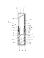
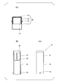
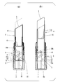
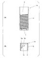
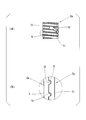
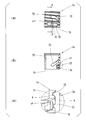
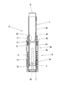
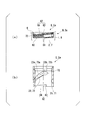
- FIG. 1 It is a side sectional view showing a lipstick container of a 1st embodiment of the present invention. It is a figure which shows the outer cylinder and inner cylinder in the lipstick container of 1st Embodiment, (a) is front sectional drawing of an outer cylinder, (b) is a front view of an outer cylinder, (c) is an inner cylinder Front sectional drawing of (d) is a front view of an inner cylinder. It is a figure which shows the inner cylinder in the lipstick container of 1st Embodiment, (a) is a side sectional view, (b) is a front view.
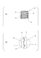
- the lipstick container of 1st Embodiment WHEREIN It is a figure which shows the state when drawing out a lipstick to a fixed position, (a) is side surface sectional drawing, (b) is front sectional drawing.
- the lipstick container of 1st Embodiment is a figure which shows the state at the time of use, (a) is side surface sectional drawing when consuming a lipstick in a fixed position, (b) when drawing out a lipstick from the state of (a) Side sectional view of FIG.
- the lipstick container of 1st Embodiment WHEREIN It is a side sectional view when the front-end
- it is a side sectional view showing the state when drawing out a lipstick to a fixed position.
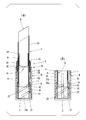
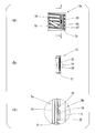
- the lipstick container of the modification of 1st Embodiment WHEREIN It is a figure which shows the state at the time of use, (a) is side surface sectional drawing when consuming lipstick in a fixed position, (b) is lipstick from the state of (a) It is a side sectional view when extending. It is side surface sectional drawing which shows the lipstick container of 2nd Embodiment of this invention. It is a figure which shows the outer cylinder and inner cylinder of 2nd Embodiment, (a) is front sectional drawing of an outer cylinder, (b) is front sectional drawing of an inner cylinder.
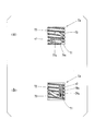
- FIG. 14 It is a figure which shows the inner cylinder which is a modification of 2nd Embodiment, (a) is a front view of the inner cylinder which changed (a) of FIG. 14, (b) has changed (a) of FIG. It is a front view of an inner cylinder.
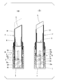
- the lipstick container of 2nd Embodiment it is a side sectional view when the lipstick is drawn out to a fixed position.
- Front sectional drawing which shows, (b) is a front sectional view of an inner cylinder.
- the vertical direction is referred to as “axial direction”
- the horizontal direction is referred to as “horizontal direction” or “direction orthogonal to the axial direction”
- upper direction is referred to as “upper”
- lower direction is referred to as “upper”.
- the axial direction is also a direction along the central axis of a container main body B (outer cylindrical body D, inner cylindrical body E, middle cylindrical body F, and middle disc body G) described later.
- the lipstick container A of 1st Embodiment which concerns on this invention is demonstrated with reference to FIGS. 1-7.
- the lipstick container A includes a container body B for delivering the lipstick k by a turning operation, and a cap C detachably mounted so as to cover the upper portion of the container body B.
- the container body B has a bottomed cylindrical outer cylinder D, an inner cylinder E whose outer peripheral surface is screwed to the inner peripheral surface of the outer cylinder D, and a middle cylinder which rotatably supports the inner cylinder E.
- a body F, and a center plate body G which accommodates a lipstick k and which can not rotate and move up and down in the middle cylinder F are provided.
- the outer cylindrical body D is extended inward from the lower end portion of the cylindrical outer peripheral wall 1 extending in the axial (vertical) direction and the outer peripheral wall 1 And a disc-shaped bottom wall 2.
- a female screw portion 3 is screwed on the inner peripheral surface of the outer peripheral wall 1 so as to have a gentle inclination with respect to the circumferential direction and to have a small pitch as compared with a spiral groove 23 of the inner cylinder E described later. ing.
- a mounting cylinder 10 is attached to the upper portion of the outer cylinder D.
- the mounting cylinder 10 is substantially the same as the mounting cylinder 10, and the insertion cylinder 11 is non-rotatably inserted into the upper portion of the inner peripheral surface of the outer peripheral wall 1 of the outer cylinder D. It has a flange portion 12 projecting outward from the middle portion, a cap mounting portion 13 whose upper portion is attached and detached by a cap C from the flange portion 12, and an annular ridge 14 whose diameter is reduced from an upper end portion of the cap mounting portion 13.
- a seal cylinder 16 is non-rotatably attached to the inside of the mounting cylinder 10.
- the seal cylinder 16 is made of an elastic material, and the upper end of the inner peripheral surface of the seal cylinder 16 is in airtight and slidable contact with the outer peripheral surface of the middle cylindrical body F.
- the inner cylinder E is equipped with the cylindrical-shaped main-body part 21 lower than the height of the outer peripheral wall 1 of the outer cylinder D.
- the main body portion 21 is shorter than the outer cylinder D in the axial direction.
- the main body portion 21 is screwed on the outer peripheral surface of the lower portion of the main body portion 21 and has a male screw portion 22 screwed with the female screw portion 3 of the outer cylindrical portion D, and two spirals formed on the inner peripheral surface of the main body portion 21
- the groove 23 and the outer peripheral surface of the upper portion of the main body portion 21 interfere with the insertion cylindrical portion 11 of the mounting cylinder 10.
- the upper reduced diameter portion 24 is smaller in diameter than the lower portion of the main body portion 21.
- the two spiral grooves 23 are formed to have a larger pitch than the pitch of the external thread 22 engaged with the internal thread 3 of the outer cylinder D, and the upper end of the slope 23a.
- a horizontal portion 23b formed on the The inclined portion 23 a extends obliquely with respect to the circumferential direction of the main body portion 21.
- the inclined upper end is one end of the inclined portion 23a in the direction in which the inclined portion 23a extends, and is an end positioned above the other end.
- the horizontal portion 23 is a flat portion along the horizontal direction, and is also a flat portion along a direction orthogonal to the direction along the central axis of the inner cylinder E, or a flat portion along a direction parallel to the circumferential direction of the main body 21 is there.
- the two spiral grooves 23 are formed to have a pitch larger than the pitch of the external thread 22 engaged with the internal thread 3 of the outer cylinder D, but the present invention is not limited thereto. .
- the working resistance when the female screw portion 3 of the outer cylinder D and the male screw portion 22 of the inner cylinder E are screwed together is the screw groove of the inner disc G and the spiral groove of the inner cylinder E.
- the two spiral grooves 23 When it is smaller than the operation resistance at the time of screwing with 23, the two spiral grooves 23 have a pitch smaller than the pitch of the external thread 22 to be screwed with the internal thread 3 of the outer cylinder D. It may be formed.
- the inner cylindrical body F is provided rotatably with respect to the inner cylindrical body E in a state where the inner cylindrical body F is prevented from coming off inside the seal cylinder 16 by the locking projection 34 of the middle part. .
- the intermediate portion is a portion of the intermediate body F which is located substantially in the middle in the axial direction, and the locking projection 34 protrudes radially outward from the intermediate portion.
- the middle cylindrical body F includes a storage cylindrical portion 31 positioned above the locking projection 34 of the middle portion and a guide cylindrical portion 32 positioned below the locking projection 34.
- the guide cylindrical portion 32 is formed with two slit portions 33 extending in the axial direction and facing each other. The two slit portions 33 are opposed in the radial direction of the guide cylindrical portion 32.
- the inner disc body G is located at the upper part, and a cylindrical disc side wall 41 accommodating the lipstick k And a ring-shaped plate bottom wall 42 having a central portion open, and radially projecting from the inner peripheral surface of the plate side wall 41 in order to hold the lower portion of the lipstick k on the inner plate G.
- the cylindrical guide cylinder wall is provided with a plurality of axially extending storage ribs 43 and a lower end portion of the countersunk side wall 41 and the outer peripheral surface is in sliding contact with the inner peripheral surface of the guide cylindrical portion 32 of the middle cylindrical body F. And 44.
- Screwing pins 45 are provided in a protruding manner.
- the screwing pin 45 protrudes radially outward from the guide cylinder wall 44.
- the cap C includes a disc-like top wall 51 having a bulge from the peripheral edge toward the center, and a cylindrical side circumferential wall 52 hanging from the outer edge of the top wall 51.
- the side peripheral wall 52 is formed so as to have an inner diameter that the inner peripheral surface contacts the outer peripheral surface of the cap mounting portion 13 of the mounting cylinder 10 and is fitted to the mounting cylinder 10.
- tip part of the lipstick k protrudes from the storage cylinder part 31 of the inner cylinder F, and the lipstick k can be used.
- the horizontal portion 23 b of the spiral groove 23 may form an opening penetrating the main body portion 21 of the inner cylindrical body E.
- the maximum amount of extension of the lipstick k can be set.
- the size of the pitch of the spiral groove 23 formed in the inner cylindrical body E and the pitch of the female screw portion 3 formed in the outer cylindrical body D can be freely set, and the amount (length) of the lipstick k to be fed out It can be selected as appropriate.
- the screwing pin 45 of the inner disc body G has a small operating resistance when screwed into the spiral groove 23 of the inner cylindrical body E, so the inner disc body G smoothly forms the slit portion 33 of the inner cylindrical body F.
- the tip of the lipstick k can be returned to the inside of the storage cylinder 31.
- the inner cylindrical body E is the inner periphery of the outer cylindrical body D by the rotation of the female screw portion 3 of the outer cylindrical body D screwed with the male screw portion 22. Roll up little by little while being restricted from rotating along the surface. That is, the inner cylinder E is separated from the bottom wall 2 of the outer cylinder D.
- the inner plate G containing the lipstick k rolls up along the slit portion 33 of the inner cylinder F.
- the tip part of the lipstick k protrudes from the storage cylinder part 31 of the middle cylinder F, and the lipstick k can be used.
- the inner cylinder E can be advanced to the upper limit position where the upper end of the inner cylinder E abuts on the locking projection 34 of the middle cylinder F.
- the screwing pin 45 of the inner disc body G has an operation resistance when the screwing pin 45 of the inner disc body G and the spiral groove 23 of the inner cylindrical body E are engaged with the spiral groove 23 of the inner cylinder E
- the inner disc body G smoothly and middle cylinder It can be lowered along the slit 33 of the body F, and the tip of the lipstick k can be returned into the storage cylinder 31.
- the inner cylinder E When the inner cylinder E is rotated clockwise with respect to the middle cylinder F (when the outer cylinder D is viewed from the lower side in the axial direction), the inner cylinder E is a female screw of the outer cylinder D screwed with the male screw 22. By rotation of 3, along with the inner peripheral surface of the outer cylinder D, it rolls up, controlling rotation.
- the lipstick container A includes a container body B for delivering the lipstick k by a turning operation, and a cap C detachably mounted so as to cover the upper portion of the container body B.
- the container body B has a bottomed cylindrical outer cylinder Da, an inner cylinder Ea whose outer peripheral surface is screwed to the inner peripheral surface of the outer cylinder Da, and a middle cylinder which rotatably supports the inner cylinder Ea.
- a body F, and a center plate body G which accommodates a lipstick k and which can not rotate and move up and down in the middle cylinder F are provided.
- the outer cylindrical body Da has a cylindrical outer peripheral wall 6 extending in the axial direction, and a bottom wall 7 extending inward from the lower end portion of the outer peripheral wall 6.
- a screw thread portion 8 is formed on the inner peripheral surface of the outer peripheral wall 6 from the lower end portion to the middle of the upper portion so as to be screwed with a screw groove portion 72 of an inner cylindrical body Ea described later.
- the mounting cylinder 60 is attached to the upper part of the outer cylinder Da.
- a seal cylinder 61 is non-rotatably attached to the inside of the mounting cylinder 60.
- the seal cylinder 61 is made of an elastic material, and the upper end of the inner peripheral surface of the seal cylinder 61 is in airtight and slidable contact with the outer peripheral surface of the middle cylindrical body F.
- the inner cylindrical body Ea has a cylindrical main body 71 lower than the height of the outer peripheral wall 6 of the outer cylindrical body Da, and the lower end to the upper end of the outer peripheral surface of the main body 71 It has a screw groove 72 (screw portion) screwed up to the screw thread portion 8 of the outer cylindrical body Da, and two spiral grooves 73 formed by penetrating the main body portion 71 in the radial direction. Further, the two spiral grooves 73 are formed in the inclined portion 73a formed at a pitch larger than the pitch of the screw groove 72 engaged with the screw thread portion 8 of the outer cylinder Da and the inclined upper end of the inclined portion 73a. And a horizontal portion 73b.
- the horizontal portion 73b is a flat portion along the horizontal direction and is also a flat portion along a direction perpendicular to the direction along the central axis of the inner cylinder Ea, and is also a flat portion along a direction parallel to the circumferential direction of the main body 71 is there.
- the screw groove 72 and the screw thread 8 of the outer cylinder Da are screwed into the screw groove 72 screwed on the outer peripheral surface of the main body 71.
- the interference protrusion 74 is formed along the upper surface of the screw groove 72 only one turn from the lower end of the main body 71. That is, the interference projection 74 is an interference projection which protrudes downward from the upper surface of the screw groove 72 and extends along the upper surface for one rotation starting from the lower end of the main body 71 in the screw groove 72.
- the interference protrusion 74 is formed along the upper surface of the screw groove 72, but is not limited thereto.
- the interference projection 74 may be formed on any portion of the screw groove 72.
- the interference projection 74 is formed along the bottom of the screw groove 72. It may be done. That is, the interference projection 74 protrudes outward in the radial direction of the main body 71 from the bottom of the screw groove 72, and the bottom of the screw groove 72 in one turn from the lower end of the main body 71 in the screw groove 72. It may be an interference protrusion extending along the Alternatively, the screw groove 72 may be alternately provided on the upper surface and the lower surface. That is, the interference projection 74 includes a first interference projection projecting downward from the upper surface of the screw groove 72 and a second interference projection projecting upward from the lower surface of the screw groove 72. The first and second interference protrusions may be alternately provided on the upper surface and the lower surface of the screw groove 72 for one rotation starting from the lower end portion of the main body 71.
- the interference protrusion 74 is provided only for one turn of the screw groove 72 starting from the lower end of the main body 71. This is because, as shown in (a) of FIG. 11, when the inner cylindrical body Ea is raised along the inner circumferential surface of the outer cylindrical body Da, the screw thread portion 8 of the outer cylindrical body Da is inside the outer peripheral wall 6 It is because it is not screwed to the upper end of a surrounding surface. This is because it is easier to manufacture by reducing the number of turns of the screw thread portion 8 to be screwed in forming the outer cylinder Da.
- the interference projection 74 may be formed in any portion of the entire length of the screw groove portion 72. Absent.
- the interference protrusions 74 need not be formed continuously along the screw groove 72, but may be formed intermittently.
- the inner cylindrical body F is provided rotatably with respect to the inner cylindrical body Ea in a state where the inner cylindrical body F is prevented from coming off inside the seal cylinder 61 by the locking projection 34 of the middle part. .
- the middle portion is located approximately at the middle of the axial direction of the intermediate F.
- the middle cylindrical body F includes a storage cylindrical portion 31 positioned above the locking projection 34 of the middle portion, and a guide cylindrical portion 32 positioned below the locking projection 34.
- the guide cylindrical portion 32 is formed with two slit portions 33 extending in the axial direction and facing each other. The two slit portions 33 are opposed in the radial direction of the guide cylindrical portion 32.
- the inner plate body G is a ring located at the upper portion and formed inward from the lower end portion of the cylindrical plate side wall 41 storing the lipstick k and the lower end portion of the plate side wall 41. And a plurality of storage ribs extending in the axial direction and protruding in the radial direction from the inner peripheral surface of the countersunk side wall 41 in order to hold the lower portion of the bottom plate 42 of the 43 and a cylindrical guide cylinder wall 44 which is vertically provided from the lower end of the countersunk side wall 41 and whose outer peripheral surface is in sliding contact with the inner peripheral surface of the guide cylindrical portion 32 of the middle cylindrical body F.
- the cap C includes a disc-like top wall 51 having a bulge from the peripheral edge toward the center, and a cylindrical side circumferential wall 52 hanging from the outer edge of the top wall 51.
- the peripheral wall 52 is fitted to the mounting cylinder 60 such that the inner circumferential surface is in contact with the outer peripheral surface of the mounting cylinder 60.
- the bulge of the top 51 bulges upward.
- the cap C is removed from the container body B of the lipstick container A shown in FIG. Furthermore, after removing the inner cover 50 from the middle cylindrical body F, while holding the storage cylindrical portion 31 of the middle cylindrical body F with fingers, the outer peripheral wall 6 of the outer cylindrical body Da against the middle cylindrical body F (the outer cylinder When the body D is pivoted clockwise as viewed from the lower side in the axial direction, the working resistance when the screw thread portion 8 of the outer cylindrical body Da and the screw groove portion 72 of the inner cylindrical body Ea are screwed together is shown in FIG. And as shown in FIG.
- the screwing pin 45 screwed into the spiral groove 73 of the inner cylindrical body Ea of the inner disc body G is the slit 33 of the inner cylindrical body F.
- the screwing pin 45 of the inner tray G lifts from the inclined portion 73a of the spiral groove 73 to the continuous horizontal portion 73b.
- the inner plate G stops moving up at a fixed position, and as shown in FIG. 17, the tip of the lipstick k protrudes from the storage cylinder 31 of the inner cylinder F, and uses the lipstick k. Can.
- the interference protrusion 74 is formed in the screw groove portion 72 of the inner cylinder Ea. Therefore, the working resistance at the time when the screw thread portion 8 of the outer cylindrical body Da and the screw groove portion 72 of the inner cylindrical body Ea are screwed together is the screwing pin 45 of the inner disc G and the spiral groove 73 of the inner cylindrical body Ea. It can be stably increased more than the operation resistance when screwing together.
- the shape and size of the interference protrusion 74 formed in the screw groove portion 72 of the inner cylindrical body Ea can be appropriately set in accordance with the required magnitude of the operating resistance.
- the interference protrusion 77 extends radially outward of the valve moving portion 76 at the central portion of the valve moving portion 76 in the direction in which the screw groove 72 extends. Protruding towards.
- the valve moving portion 76 is formed laterally along the screw groove 72, but is not limited thereto.
- the valve moving portion may be a valve moving portion 78 formed in the longitudinal direction so as to intersect the screw groove 72 as shown in (a) to (c) of FIG. In this case, in the thin-walled valve moving portion 78, the left and right ends are separated by a gap s2 along the vertical direction intersecting the screw groove portion 72, and the interference projection 79 is formed at the position intersecting the screw groove portion 72 of the valve moving portion 78. It is done.
- the main body portion 71 has a gap s2 extending along the longitudinal direction intersecting the screw groove portion 72, and the thin-walled valve operating portion 78 is opposed to the circumferential direction forming the gap s2 in the main body portion 71.
- the interference projection 77 is formed in such a manner that the left and right ends are separated from the two surfaces, and extends in the longitudinal direction intersecting the screw groove 72, and the interference projection 77 intersects the screw groove 72 of the valve operating portion 78. Is formed.
- Both ends of the valve moving parts 76 and 78 shown in (a) to (c) of FIG. 14 and (a) to (c) of FIG. 15 are connected to the main body part 71. That is, both ends of the valve moving portion 76 in the extending direction of the screw groove 72 are connected to the main body 71, and both ends of the valve moving portion 78 in the vertical direction intersecting the screw groove 72 are connected to the main body 71 It is done.
- the valve moving part 76 a having a cantilever structure in which only one side is connected to the main body 71 and the other side is separated by the gap s1 or s2 , 78a may be used. That is, as shown in FIG.
- one end of the valve moving portion in the extending direction of the screw groove 72 is connected to the main body 71, and the other end is separated by the gap s1.
- It may be the valve moving part 76a which is not connected to the part 71, and as shown in FIG. 16 (b), one end of the both ends in the vertical direction intersecting the screw groove 72 is connected to the main body 71, The other end may be a valve moving portion 78 a separated by the gap s 2 and not connected to the main body 71.
- the valve operating parts 76, 76a, 78, 78a can stabilize the operating resistance if they are formed at least one place in the inner cylinder Ea, but a plurality of valve operating parts are mutually on the circumference of the inner cylinder Ea.
- valve moving parts 76 and 76a extending in the extending direction of the screw groove 72 are formed at positions facing each other in the extending direction of the screw groove 72 on the outer peripheral surface of the inner cylinder Ea. It is preferable that a plurality of vertically extending valve moving portions 78, 78a intersecting the screw groove portion 72 be formed at positions facing each other in the radial direction on the outer peripheral surface of the inner cylinder Ea.
- the interference projections 77, 77a, 79, 79a supported by the valve moving portions 76, 76a, 78, 78a instead of the interference projections 74 are formed on the inner cylinder Ea. 74 and the interference projections 77, 77a, 79, 79a supported by the valve operating portions 76, 76a, 78, 78a may be used in combination.
- the operating resistance when the screw thread portion 8 of the outer cylindrical body Da and the screw groove portion 72 of the inner cylindrical body Ea are screwed is an interference protrusion on the screw groove portion 72 of the inner cylindrical body Ea.
- the thin-walled valve member 76, 76a, 78, 78a having 77, 77a, 79, 79a, the screw thread portion 8 of the outer cylinder Da is in contact with the interference projection 77, 77a, 79, 79a.
- the interference protrusions 77, 77a, 79 which provide the operation resistance even if there is a dimensional error in the screw thread portion 8 of the outer cylinder Da and the screw groove 72 of the inner cylinder Ea.
- the elastically deformable valve moving portions 76, 76a, 78, 78a, 79a can be made to project and retract in the radial direction.
- the lipstick container of the present invention comprises an engaging portion provided on the outer cylindrical body D, Da, and an engaged portion provided on the inner cylindrical body E, Ea and capable of engaging with the engaging portion.
- the engagement portion is a rib 80 provided at the lower end portion of the inner peripheral surface of the outer peripheral wall 1 or 6 of the outer cylindrical body D, Da.
- the step is provided at the lower end of the outer peripheral surface of the main body 21 or 71 of the inner cylindrical body E or Ea and can be engaged with the rib 80 82 may be sufficient.
- the rib 80 is formed near one end (lower end) located on the lower side of both ends in the spiral direction of the screw thread portion 8 and radially inward from the inner peripheral surface of the outer peripheral wall 6 It is a projection which is projected toward.
- the spiral direction of the thread portion 8 means a direction along the spiral shape of the thread portion 8 itself.
- the rib 80 is a protrusion extending along the spiral direction of the screw thread portion 8 as shown in FIG. Although a protrusion such as the rib 80 is described as an example, the rib 80 may be replaced with a protrusion having another shape.
- the shape of the protrusion is not limited as long as the protrusion can be in contact with the side surface 83 of the step 82 by lowering the inner cylindrical members E and Ea as described later. Therefore, instead of the rib 80, a projection may be provided which does not extend along the spiral direction of the screw thread portion 8.
- the stepped portion 82 is a notch formed by cutting the main body portion 71 of the inner cylindrical body E, Ea upward from the lower end face thereof.
- the step 82 has a side 83 facing in the direction of rotation so that the inner cylinder E, Ea rolls down, and an upper surface 84 extending from the upper end of the side 83 along the spiral direction of the screw groove 72 and facing downward.
- the spiral direction of the screw groove 72 means the direction along the spiral shape of the screw groove 72 itself.
- the stepped portion 80 is a notch having a shape shown in (a) and (b) of FIG. Although a notch such as the step 80 is described as an example, a notch having another shape may be provided instead of the step 80.
- the shape of the notch is not limited as long as the notch is provided with a side surface that can abut against the rib 80 by lowering the inner cylinder E, Ea. Therefore, instead of the step portion 80, a cutting having a shape which is recessed radially inward from the outer peripheral surface of the main body portions 21, 71 without penetrating the main body portions 21, 71 of the inner cylindrical bodies E, Ea in the radial direction. A notch may be provided.
- the side surface 83 forming the step 82 is one end (upper end) 81 located on the upper side of both ends of the rib 80 in the direction along the extending rib 80 , Can be gradually brought close to contact.
- the ribs 80 (protrusions, engaging portions) of the outer cylindrical bodies D, Da and the step portions 82 (notches, engaged portions) of the inner cylindrical bodies E, Ea can be engaged with each other.
- a rib 80 protrusion, engaging portion is formed near one end (lower end) located on the lower side of both ends in the spiral direction of the screw thread portion 8.
- the inner cylinder bodies E and Ea You can stop the As a result, next, when the inner cylindrical bodies E and Ea move up with respect to the outer cylindrical bodies D and Da, the main body portions 21 and 71 of the inner cylindrical bodies E and Ea and the bottom walls of the outer cylindrical bodies D and Da Since the inner cylinder E and Ea move up from a state where they are separated by a predetermined distance from each other in the axial direction, the main body 21 and 71 of the inner cylinder E and Ea and the bottom of the outer cylinder D and Da The surface contact with the walls 2 and 7 can prevent the inner cylinders E and Ea from being easily carried up with respect to the outer cylinders D and Da.
- the above-mentioned predetermined distance is suitably set by adjusting the position of rib 80 (protrusion,
- the lipstick container of the present invention can be suitably used as a lipstick container for accommodating recent soft lipsticks, since it is possible for the user to prevent the lipstick from being broken by mistake by the user at the start of use.
Landscapes
- Engineering & Computer Science (AREA)
- Mechanical Engineering (AREA)
- Containers And Packaging Bodies Having A Special Means To Remove Contents (AREA)
Priority Applications (5)
| Application Number | Priority Date | Filing Date | Title |
|---|---|---|---|
| KR1020207017106A KR102542457B1 (ko) | 2017-12-27 | 2018-12-27 | 립스틱 용기 |
| CN201880084100.3A CN111526755B (zh) | 2017-12-27 | 2018-12-27 | 口红容器 |
| EP18895191.7A EP3733018B1 (en) | 2017-12-27 | 2018-12-27 | Lipstick container |
| US16/957,879 US11304496B2 (en) | 2017-12-27 | 2018-12-27 | Lipstick container |
| JP2019562137A JP6929384B2 (ja) | 2017-12-27 | 2018-12-27 | 口紅容器 |
Applications Claiming Priority (4)
| Application Number | Priority Date | Filing Date | Title |
|---|---|---|---|
| JP2017-250775 | 2017-12-27 | ||
| JP2017250775 | 2017-12-27 | ||
| JP2018069860 | 2018-03-30 | ||
| JP2018-069860 | 2018-03-30 |
Publications (1)
| Publication Number | Publication Date |
|---|---|
| WO2019131821A1 true WO2019131821A1 (ja) | 2019-07-04 |
Family
ID=67067623
Family Applications (1)
| Application Number | Title | Priority Date | Filing Date |
|---|---|---|---|
| PCT/JP2018/047993 WO2019131821A1 (ja) | 2017-12-27 | 2018-12-27 | 口紅容器 |
Country Status (6)
| Country | Link |
|---|---|
| US (1) | US11304496B2 (ko) |
| EP (1) | EP3733018B1 (ko) |
| JP (1) | JP6929384B2 (ko) |
| KR (1) | KR102542457B1 (ko) |
| CN (1) | CN111526755B (ko) |
| WO (1) | WO2019131821A1 (ko) |
Cited By (2)
| Publication number | Priority date | Publication date | Assignee | Title |
|---|---|---|---|---|
| JP2021133112A (ja) * | 2020-02-28 | 2021-09-13 | 株式会社吉野工業所 | 繰出容器 |
| JP7427343B2 (ja) | 2020-11-30 | 2024-02-05 | 株式会社吉野工業所 | 繰出し容器 |
Families Citing this family (3)
| Publication number | Priority date | Publication date | Assignee | Title |
|---|---|---|---|---|
| US11717072B2 (en) * | 2018-07-11 | 2023-08-08 | Pat Mcgrath Cosmetics Llc | Lipstick arrangement |
| KR102568096B1 (ko) | 2022-12-27 | 2023-08-18 | 오윤탁 | 립스틱 케이스 |
| KR102646439B1 (ko) * | 2023-12-04 | 2024-03-11 | 지윤정 | 탄성 걸림 구조를 갖는 스틱형 화장품 용기 |
Citations (9)
| Publication number | Priority date | Publication date | Assignee | Title |
|---|---|---|---|---|
| JPS6073418U (ja) * | 1983-10-25 | 1985-05-23 | 釜屋化学工業株式会社 | 繰出容器 |
| JPS64838U (ko) | 1987-06-17 | 1989-01-05 | ||
| JP2004000343A (ja) | 2002-05-31 | 2004-01-08 | Yoshino Kogyosho Co Ltd | 棒状化粧料の収納皿 |
| JP2006334368A (ja) * | 2005-06-05 | 2006-12-14 | Mikio Kuzuu | 口紅等の収納容器 |
| JP2008036372A (ja) * | 2006-08-05 | 2008-02-21 | Mikio Kuzuu | 口紅等の収納容器 |
| JP2008043590A (ja) * | 2006-08-18 | 2008-02-28 | Tokiwa Corp | 充填物押出容器 |
| JP2008055025A (ja) * | 2006-09-01 | 2008-03-13 | Suzuno Kasei Kk | 棒状化粧材繰り出し容器 |
| JP2017025075A (ja) | 2011-08-12 | 2017-02-02 | 三菱瓦斯化学株式会社 | レジスト組成物、レジストパターン形成方法、それに用いるポリフェノール化合物及びそれから誘導され得るアルコール化合物 |
| JP2018069860A (ja) | 2016-10-26 | 2018-05-10 | 株式会社ヴァレオジャパン | 車両用の空調装置 |
Family Cites Families (8)
| Publication number | Priority date | Publication date | Assignee | Title |
|---|---|---|---|---|
| GB2026983A (en) * | 1978-07-20 | 1980-02-13 | Cardia E | Cosmetics containers |
| JPS64838Y2 (ko) | 1984-12-28 | 1989-01-10 | ||
| US5749664A (en) * | 1994-07-08 | 1998-05-12 | Hidan Co. | Cosmetic container having an insert sleeve to improve air tightness and rotational characteristics |
| JP2736039B2 (ja) * | 1994-08-25 | 1998-04-02 | 株式会社トキワ | 化粧料繰り出し容器 |
| US7901152B2 (en) * | 2003-11-13 | 2011-03-08 | The Sun Products Corporation | Fabric cleaning fluid and dispensing device |
| US20130230347A1 (en) * | 2012-07-24 | 2013-09-05 | Rnd Group Llc | Slide type lipstick case structure |
| WO2013191523A2 (ko) | 2013-07-24 | 2013-12-27 | Kim Yoon Hoi | 슬라이드형 립스틱 용기 |
| CN206761066U (zh) * | 2017-04-24 | 2017-12-19 | 苏州佑嘉塑胶科技有限公司 | 一种旋拧式防脱口红管 |
-
2018
- 2018-12-27 US US16/957,879 patent/US11304496B2/en active Active
- 2018-12-27 EP EP18895191.7A patent/EP3733018B1/en active Active
- 2018-12-27 JP JP2019562137A patent/JP6929384B2/ja active Active
- 2018-12-27 CN CN201880084100.3A patent/CN111526755B/zh active Active
- 2018-12-27 KR KR1020207017106A patent/KR102542457B1/ko active IP Right Grant
- 2018-12-27 WO PCT/JP2018/047993 patent/WO2019131821A1/ja unknown
Patent Citations (9)
| Publication number | Priority date | Publication date | Assignee | Title |
|---|---|---|---|---|
| JPS6073418U (ja) * | 1983-10-25 | 1985-05-23 | 釜屋化学工業株式会社 | 繰出容器 |
| JPS64838U (ko) | 1987-06-17 | 1989-01-05 | ||
| JP2004000343A (ja) | 2002-05-31 | 2004-01-08 | Yoshino Kogyosho Co Ltd | 棒状化粧料の収納皿 |
| JP2006334368A (ja) * | 2005-06-05 | 2006-12-14 | Mikio Kuzuu | 口紅等の収納容器 |
| JP2008036372A (ja) * | 2006-08-05 | 2008-02-21 | Mikio Kuzuu | 口紅等の収納容器 |
| JP2008043590A (ja) * | 2006-08-18 | 2008-02-28 | Tokiwa Corp | 充填物押出容器 |
| JP2008055025A (ja) * | 2006-09-01 | 2008-03-13 | Suzuno Kasei Kk | 棒状化粧材繰り出し容器 |
| JP2017025075A (ja) | 2011-08-12 | 2017-02-02 | 三菱瓦斯化学株式会社 | レジスト組成物、レジストパターン形成方法、それに用いるポリフェノール化合物及びそれから誘導され得るアルコール化合物 |
| JP2018069860A (ja) | 2016-10-26 | 2018-05-10 | 株式会社ヴァレオジャパン | 車両用の空調装置 |
Non-Patent Citations (1)
| Title |
|---|
| See also references of EP3733018A4 |
Cited By (3)
| Publication number | Priority date | Publication date | Assignee | Title |
|---|---|---|---|---|
| JP2021133112A (ja) * | 2020-02-28 | 2021-09-13 | 株式会社吉野工業所 | 繰出容器 |
| JP7308780B2 (ja) | 2020-02-28 | 2023-07-14 | 株式会社吉野工業所 | 繰出容器 |
| JP7427343B2 (ja) | 2020-11-30 | 2024-02-05 | 株式会社吉野工業所 | 繰出し容器 |
Also Published As
| Publication number | Publication date |
|---|---|
| KR102542457B1 (ko) | 2023-06-12 |
| CN111526755A (zh) | 2020-08-11 |
| EP3733018A4 (en) | 2021-09-15 |
| EP3733018A1 (en) | 2020-11-04 |
| KR20200101916A (ko) | 2020-08-28 |
| US11304496B2 (en) | 2022-04-19 |
| EP3733018B1 (en) | 2022-04-27 |
| CN111526755B (zh) | 2023-03-24 |
| US20200337439A1 (en) | 2020-10-29 |
| JP6929384B2 (ja) | 2021-09-01 |
| JPWO2019131821A1 (ja) | 2020-09-24 |
Similar Documents
| Publication | Publication Date | Title |
|---|---|---|
| WO2019131821A1 (ja) | 口紅容器 | |
| US9474349B2 (en) | Cosmetic dispenser with frictional resistance | |
| US9642439B2 (en) | Cosmetic dispenser with crenelated wall for frictional resistance | |
| JP7206038B2 (ja) | 繰出容器 | |
| JP2005237894A (ja) | 棒状化粧料繰り出し容器 | |
| WO2020153241A1 (ja) | 繰り出し容器 | |
| JP2017012725A (ja) | 繰出容器 | |
| JP7308698B2 (ja) | 繰出容器 | |
| JP6817046B2 (ja) | 繰出容器 | |
| JP6980347B2 (ja) | 口紅容器 | |
| JP7175846B2 (ja) | 繰出し容器 | |
| JP7246273B2 (ja) | 繰出容器 | |
| WO2023085176A1 (ja) | 繰出し容器 | |
| JP2020025622A (ja) | 繰出容器 | |
| KR102569160B1 (ko) | 정량 출몰 조절용 다각형 스틱 용기 | |
| JP7309273B2 (ja) | 繰出し容器 | |
| JP3221247U (ja) | 棒状化粧料容器 | |
| JP7211916B2 (ja) | 繰出し容器 | |
| JP7016576B2 (ja) | 繰り出し容器 | |
| WO2020145324A1 (ja) | 棒状材繰出容器 | |
| JP2023144260A (ja) | 繰出容器 | |
| JP2023111706A (ja) | 繰出容器 | |
| JP4186183B2 (ja) | 棒状化粧料繰り出し容器 | |
| JPH0238664Y2 (ko) | ||
| JP2020018463A (ja) | 繰出容器 |
Legal Events
| Date | Code | Title | Description |
|---|---|---|---|
| 121 | Ep: the epo has been informed by wipo that ep was designated in this application |
Ref document number: 18895191 Country of ref document: EP Kind code of ref document: A1 |
|
| ENP | Entry into the national phase |
Ref document number: 2019562137 Country of ref document: JP Kind code of ref document: A |
|
| NENP | Non-entry into the national phase |
Ref country code: DE |
|
| ENP | Entry into the national phase |
Ref document number: 2018895191 Country of ref document: EP Effective date: 20200727 |