WO2019131632A1 - 排気室及び蒸気タービン - Google Patents
排気室及び蒸気タービン Download PDFInfo
- Publication number
- WO2019131632A1 WO2019131632A1 PCT/JP2018/047571 JP2018047571W WO2019131632A1 WO 2019131632 A1 WO2019131632 A1 WO 2019131632A1 JP 2018047571 W JP2018047571 W JP 2018047571W WO 2019131632 A1 WO2019131632 A1 WO 2019131632A1
- Authority
- WO
- WIPO (PCT)
- Prior art keywords
- axis
- guide
- diffuser
- axial direction
- downstream
- Prior art date
Links
Images


Classifications
-
- F—MECHANICAL ENGINEERING; LIGHTING; HEATING; WEAPONS; BLASTING
- F01—MACHINES OR ENGINES IN GENERAL; ENGINE PLANTS IN GENERAL; STEAM ENGINES
- F01D—NON-POSITIVE DISPLACEMENT MACHINES OR ENGINES, e.g. STEAM TURBINES
- F01D25/00—Component parts, details, or accessories, not provided for in, or of interest apart from, other groups
- F01D25/30—Exhaust heads, chambers, or the like
-
- F—MECHANICAL ENGINEERING; LIGHTING; HEATING; WEAPONS; BLASTING
- F01—MACHINES OR ENGINES IN GENERAL; ENGINE PLANTS IN GENERAL; STEAM ENGINES
- F01D—NON-POSITIVE DISPLACEMENT MACHINES OR ENGINES, e.g. STEAM TURBINES
- F01D25/00—Component parts, details, or accessories, not provided for in, or of interest apart from, other groups
- F01D25/24—Casings; Casing parts, e.g. diaphragms, casing fastenings
-
- F—MECHANICAL ENGINEERING; LIGHTING; HEATING; WEAPONS; BLASTING
- F01—MACHINES OR ENGINES IN GENERAL; ENGINE PLANTS IN GENERAL; STEAM ENGINES
- F01D—NON-POSITIVE DISPLACEMENT MACHINES OR ENGINES, e.g. STEAM TURBINES
- F01D9/00—Stators
- F01D9/02—Nozzles; Nozzle boxes; Stator blades; Guide conduits, e.g. individual nozzles
-
- F—MECHANICAL ENGINEERING; LIGHTING; HEATING; WEAPONS; BLASTING
- F02—COMBUSTION ENGINES; HOT-GAS OR COMBUSTION-PRODUCT ENGINE PLANTS
- F02C—GAS-TURBINE PLANTS; AIR INTAKES FOR JET-PROPULSION PLANTS; CONTROLLING FUEL SUPPLY IN AIR-BREATHING JET-PROPULSION PLANTS
- F02C7/00—Features, components parts, details or accessories, not provided for in, or of interest apart form groups F02C1/00 - F02C6/00; Air intakes for jet-propulsion plants
-
- F—MECHANICAL ENGINEERING; LIGHTING; HEATING; WEAPONS; BLASTING
- F05—INDEXING SCHEMES RELATING TO ENGINES OR PUMPS IN VARIOUS SUBCLASSES OF CLASSES F01-F04
- F05D—INDEXING SCHEME FOR ASPECTS RELATING TO NON-POSITIVE-DISPLACEMENT MACHINES OR ENGINES, GAS-TURBINES OR JET-PROPULSION PLANTS
- F05D2220/00—Application
- F05D2220/30—Application in turbines
- F05D2220/31—Application in turbines in steam turbines
-
- F—MECHANICAL ENGINEERING; LIGHTING; HEATING; WEAPONS; BLASTING
- F05—INDEXING SCHEMES RELATING TO ENGINES OR PUMPS IN VARIOUS SUBCLASSES OF CLASSES F01-F04
- F05D—INDEXING SCHEME FOR ASPECTS RELATING TO NON-POSITIVE-DISPLACEMENT MACHINES OR ENGINES, GAS-TURBINES OR JET-PROPULSION PLANTS
- F05D2240/00—Components
- F05D2240/10—Stators
- F05D2240/12—Fluid guiding means, e.g. vanes
-
- F—MECHANICAL ENGINEERING; LIGHTING; HEATING; WEAPONS; BLASTING
- F05—INDEXING SCHEMES RELATING TO ENGINES OR PUMPS IN VARIOUS SUBCLASSES OF CLASSES F01-F04
- F05D—INDEXING SCHEME FOR ASPECTS RELATING TO NON-POSITIVE-DISPLACEMENT MACHINES OR ENGINES, GAS-TURBINES OR JET-PROPULSION PLANTS
- F05D2240/00—Components
- F05D2240/10—Stators
- F05D2240/14—Casings or housings protecting or supporting assemblies within
-
- F—MECHANICAL ENGINEERING; LIGHTING; HEATING; WEAPONS; BLASTING
- F05—INDEXING SCHEMES RELATING TO ENGINES OR PUMPS IN VARIOUS SUBCLASSES OF CLASSES F01-F04
- F05D—INDEXING SCHEME FOR ASPECTS RELATING TO NON-POSITIVE-DISPLACEMENT MACHINES OR ENGINES, GAS-TURBINES OR JET-PROPULSION PLANTS
- F05D2240/00—Components
- F05D2240/50—Bearings
-
- F—MECHANICAL ENGINEERING; LIGHTING; HEATING; WEAPONS; BLASTING
- F05—INDEXING SCHEMES RELATING TO ENGINES OR PUMPS IN VARIOUS SUBCLASSES OF CLASSES F01-F04
- F05D—INDEXING SCHEME FOR ASPECTS RELATING TO NON-POSITIVE-DISPLACEMENT MACHINES OR ENGINES, GAS-TURBINES OR JET-PROPULSION PLANTS
- F05D2250/00—Geometry
- F05D2250/70—Shape
Definitions
- the present invention relates to an exhaust chamber and a steam turbine.
- Priority is claimed on Japanese Patent Application No. 2017-253815, filed Dec. 28, 2017, the content of which is incorporated herein by reference.
- a diffuser for pressure recovery of the working fluid is often provided downstream of the final stage moving blades.
- the working fluid exhausted along the axis of the rotor shaft is formed to change its direction radially outward around the rotor shaft, for example, due to the layout or the like.
- the exhaust loss may be increased by changing the direction of the exhaust.
- the bearing cone shape of the diffuser is formed asymmetrically on the exhaust side and the exhaust side of the outer casing in order to reduce the exhaust loss from the final stage moving blade of the steam turbine to the condenser.
- Patent Document 3 proposes a technique in which the flow guide of the diffuser is formed asymmetrically on the exhaust side and the exhaust side of the outer casing.
- the exhaust chamber comprises an inner casing, an outer casing and a diffuser.
- the inner casing encloses the rotor from the outside in the radial direction centering on the axis of the rotor shaft, and forms a first space between the rotor and the rotor in which fluid flows in the direction in which the axis extends.
- the outer casing encloses the rotor and the inner casing, and forms a second space between the inner casing and the second space in which the fluid having flowed through the first space is exhausted, and the first side in the direction orthogonal to the axis Have an exit.
- the diffuser is disposed downstream of the inner casing to form a diffuser space communicating with the first space, and is directed radially outward toward the downstream side, and the first space is communicated with the second space
- the diffuser has a cylindrical shape extending downstream in the axial direction so as to be continuous with the outer peripheral surface of the rotor shaft forming the first space, and a bearing cone that gradually expands in diameter toward the downstream side in the axial direction Have.
- the downstream edge of the bearing cone is a second side opposite to the first side than a distance between the first cone end in the direction orthogonal to the axis and the axis.
- the second embodiment has an oval shape in which the distance between the second cone end and the axis is larger.
- the downstream edge of the bearing cone in the first aspect is a second end of the bearing cone which is opposite to the first side than a distance between the first cone end and the axis in a direction perpendicular to the axis.
- the distance between the side second cone end and the axis is greater.
- the length of the diffuser space on the second side can be increased. Therefore, the area where the backflow occurs can be eliminated. Therefore, the pressure loss can be reduced to improve the performance.
- the diffuser according to the first aspect has a cylindrical shape extending from the downstream edge of the inner casing to the downstream side in the axial direction, and is directed to the downstream side in the axial direction Therefore, it may have a flow guide which gradually expands in diameter.
- the flow guide may include a first guide portion formed on the first side of the axis and a second guide portion formed on the second side of the axis.
- the radial distance between the axis and the second side guide end located on the most second side of the second guide portion is the same in the axial direction as the second side guide end It may be made larger than the distance in the diameter direction of the 1st above-mentioned guide part of the position, and the above-mentioned axis.
- the angle between the tangent at the second side guide end and the axis is greater than the angle between the axis of the second guide at the same position in the axial direction and the axis of the first guide.
- the diffuser according to the first aspect has a cylindrical shape extending from the downstream end edge of the inner casing to the downstream side in the axial direction, and is directed to the downstream side in the axial direction Therefore, it may have a flow guide which gradually expands in diameter.
- the flow guide may include a first guide portion formed on the first side of the axis and a second guide portion formed on the second side of the axis.
- the angle between the tangent of the second guide and the axis is the tangent of the second guide and the tangent of the first guide at the same position in the axial direction, and the axis It may be made larger than the angle made.
- the flow passage area effective as the diffuser space at the outlet of the diffuser can be expanded to improve the pressure recovery performance of the diffuser.
- the first cone end on the first side according to the second or third aspect is positioned downstream of the second cone end on the second side in the axial direction. It may be done.
- the diffuser space on the first side since the flow of fluid discharged from the first space inside the inner casing is directed in the axial direction, separation is unlikely to occur on the bearing cone side. Therefore, by positioning the first cone end on the first side on the downstream side in the axial direction with respect to the second cone end on the second side, a flow passage cross-sectional area effective as a diffuser space on the first side can be obtained. It can be expanded.
- the diffuser according to the first aspect has a cylindrical shape extending from the downstream end edge of the inner casing to the downstream side in the axial direction, and proceeds toward the downstream side in the axial direction Therefore, it may have a flow guide which gradually expands in diameter.
- the flow guide may include a first guide portion formed on the first side of the axis and a second guide portion formed on the second side of the axis.
- the second cone end may be disposed axially downstream of the first cone end.
- the second guide portion according to the first aspect may be longer in axial direction than the first guide portion.
- the length of the bearing cone on the second side and the length of the flow guide can be increased, and hence the length of the diffuser space on the second side can be increased. Therefore, it is possible to suppress the occurrence of backflow on the bearing cone side and to improve the pressure recovery performance in the diffuser.
- the end with the largest distance from the axis is more than the position on the most second side in the circumferential direction about the axis. It may be arranged at a position shifted forward in the rotational direction of the rotor shaft.
- a steam turbine includes the exhaust chamber according to any one of the first to sixth aspects. With this configuration, the efficiency of the steam turbine can be improved.
- the pressure loss can be reduced to improve the performance.
- FIG. 2 shows schematic structure of the steam turbine in 1st embodiment of this invention. It is an enlarged view of the exhaust chamber in 1st embodiment of this invention. It is a figure which shows the external shape of the bearing cone seen from the axial direction in 1st embodiment of this invention, and a flow guide. It is a figure corresponded in FIG. 2 in 2nd embodiment of this invention. It is a figure corresponded in FIG. 3 in 2nd embodiment of this invention. It is a figure corresponded in FIG. 2 in the 1st modification of 2nd embodiment of this invention. It is a figure corresponded in FIG. 3 in the 1st modification of 2nd embodiment of this invention. It is a figure corresponded in FIG.
- FIG. 2 in the 2nd modification of 2nd embodiment of this invention. It is a figure corresponded in FIG. 3 in the 2nd modification of 2nd embodiment of this invention. It is a figure corresponded in FIG. 2 in 3rd embodiment of this invention. It is a figure corresponded in FIG. 3 in 3rd embodiment of this invention. It is a figure corresponded in FIG. 2 in 4th embodiment of this invention. It is a figure corresponded in FIG. 3 in 4th embodiment of this invention.
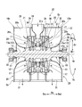
- FIG. 1 is a view showing a schematic configuration of a steam turbine according to a first embodiment of the present invention.
- the steam turbine ST of the first embodiment is a two-split exhaust steam turbine.
- the steam turbine ST includes a first steam turbine unit 10a and a second steam turbine unit 10b.
- Each of the first steam turbine unit 10 a and the second steam turbine unit 10 b is fixed to the turbine rotor (rotor) 11 rotating around the axis Ar, the casing 20 covering the turbine rotor 11, and the casing 20 And a steam inflow pipe 19.
- the circumferential direction about the axis Ar is simply referred to as the circumferential direction Dc, and the direction perpendicular to the axis Ar is referred to as the radial direction Dr.
- the side of the axis Ar is referred to as the radially inner side Dri, and the opposite side is referred to as the radially outer side Dro.
- the first steam turbine unit 10 a and the second steam turbine unit 10 b share the steam inflow pipe 19.
- the first steam turbine unit 10 a is disposed on one side of the axial direction Da with reference to the steam inlet pipe 19 except for the steam inlet pipe 19.
- the second steam turbine unit 10 b is disposed on the other side of the axial direction Da with reference to the steam inlet pipe 19 except for the steam inlet pipe 19.
- the configuration of the first steam turbine unit 10a and the configuration of the second steam turbine unit 10b are basically the same. Therefore, in the following description, the first steam turbine unit 10a will be mainly described, and the description of the second steam turbine unit 10b will be omitted.
- the side of the steam inflow pipe 19 in the axial direction Da is referred to as an axial upstream side Dau
- the opposite side is referred to as an axial downstream side Dad.
- the turbine rotor 11 has a rotor shaft 12 extending in the axial direction Da around an axis Ar and a plurality of moving blade cascades 13 attached to the rotor shaft 12.
- the turbine rotor 11 is supported by a bearing 18 rotatably around an axis Ar.
- the plurality of moving blade rows 13 are arranged in the axial direction Da.
- Each of the plurality of moving blade arrays 13 is configured of a plurality of moving blades arranged in the circumferential direction Dc.
- the turbine rotor 11 of the first steam turbine unit 10a and the turbine rotor 11 of the second steam turbine unit 10b are located on the same axis Ar and connected to each other, and integrally rotate around the axis Ar.
- the casing 20 has an inner casing 21 and an exhaust casing 25.
- the inner casing 21 and the rotor shaft 12 form a first space 21 s in an annular shape centered on the axis Ar.
- the steam (fluid) that has flowed in from the steam inflow pipe 19 flows in the first space 21s in the axial direction Da (more specifically, in the direction downstream of the axial line Dad).
- the plurality of moving blade cascades 13 of the turbine rotor 11 are disposed in the first space 21s.
- the plurality of vane arrays 17 are arranged in the first space 21 s along the axial direction Da.
- Each of the plurality of stationary blade rows 17 is disposed on the upstream side Dau of the moving blade row 13 of any one of the plurality of moving blade rows 13.
- the plurality of vane arrays 17 are fixed to the inner casing 21.
- the exhaust casing 25 has a diffuser 26 and an outer casing 30.
- the outer casing 30 encloses the turbine rotor 11 and the inner casing 21 and forms a second space 30s between the first casing 21s and the inner casing 21 in which the steam flowing through the first space 21s is discharged.
- the second space 30s communicates with the diffuser 26 and spreads in the circumferential direction Dc on the outer peripheral side of the diffuser 26.
- the outer casing 30 guides the vapor flowing from the diffuser space 26s into the second space 30s to the exhaust port 31.
- the outer casing 30 has an exhaust port (outlet) 31 on the first side (lower side in FIG. 1) in the direction orthogonal to the axis Ar.
- the outer casing 30 illustrated in this embodiment opens downward in the vertical direction.
- the steam turbine ST of this embodiment is a so-called lower exhaust type condensing steam turbine, and a condenser (not shown) for returning steam to water is connected to the exhaust port 31.
- the outer casing 30 in this embodiment includes the downstream end plate 32, the upstream end plate 34, and the side circumferential plate 36, respectively.
- the downstream end plate 32 extends from the edge of the radially outer side Dro of the bearing cone 29 to the radially outer side Dro to define the edge of the axially downstream side Dad of the second space 30s.
- the upstream end plate 34 is disposed on the axially upstream side Dau of the diffuser 26.
- the upstream end plate 34 extends from the outer circumferential surface 21 o of the inner casing 21 to the radially outer side Dro to define the edge of the axially upstream side Dau of the second space 30 s.
- the side circumferential plate 36 is connected to the downstream side end plate 32 and the upstream side end plate 34, and spreads in the axial direction Da and spreads in the circumferential direction Dc around the axis Ar, and is an edge of the radially outer side Dro of the second space 30s.
- the diffuser 26 is disposed on the axial downstream side Dad of the inner casing 21 to communicate the first space 21 s with the second space 30 s.
- the diffuser 26 forms an annular diffuser space 26s which is directed radially outward gradually toward the axial downstream side Dad.
- the steam that has flowed out from the final moving blade row 13a of the turbine rotor 11 toward the axial downstream side Dad flows into the diffuser space 26s.
- the final moving blade row 13a is the moving blade row 13 disposed on the most downstream axial side Dad among the plurality of moving blade rows 13 provided in the first steam turbine unit 10a.
- the diffuser 26 has a flow guide (or a steam guide, also referred to as an outer diffuser) 27 that defines the edge of the radially outer Dro of the diffuser space 26s, and a bearing cone (or that defines the edge of the radially inner Dri of the diffuser space 26s. , And an inner diffuser) 29).
- a flow guide or a steam guide, also referred to as an outer diffuser
- a bearing cone or that defines the edge of the radially inner Dri of the diffuser space 26s.
- an inner diffuser 29 an inner diffuser
- the bearing cone 29 is formed in a cylindrical shape extending on the axial downstream side Dad so as to be continuous with the outer peripheral surface 12 a of the rotor shaft 12 forming the first space 21 s.
- the bearing cone 29 has an annular cross section perpendicular to the axis Ar, and the diameter gradually increases toward the radially outer side Dro toward the axial downstream side Dad.
- the end 29 a of the bearing cone 29 is connected to the downstream end plate 32 of the outer casing 30.
- the flow guide 27 has a tubular shape extending from the end edge of the axial downstream side Dad of the inner casing 21 toward the axial downstream side Dad.
- the flow guide 27 has an annular cross section perpendicular to the axis Ar, and the diameter gradually increases in the downstream direction Dad.
- the flow guide 27 in this embodiment is connected to the inner casing 21.
- the exhaust chamber Ec in the present invention is constituted by the inner casing 21, the outer casing 30 and the diffuser 26.
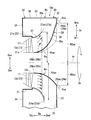
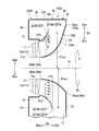
- FIG. 2 is an enlarged view of the exhaust chamber in the first embodiment of the present invention.
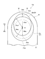
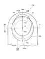
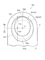
- FIG. 3 is a view showing an outline of a bearing cone and a flow guide as viewed from the axial direction in the first embodiment of the present invention.
- the exhaust chamber Ec has an asymmetric shape in the circumferential direction Dc by arranging the exhaust port 31 only on one side (first side) in the direction orthogonal to the axis Ar, and pressure in the circumferential direction Distribution occurs. Then, as shown in FIG. 2, on the side (second side) opposite to the side where the exhaust port 31 is disposed, the flow of steam discharged from the first space 21s faces the radially outer side Dro and the flow rate distribution ( In FIG.
- the inside of the diffuser 26 is biased to the flow guide 27 side (indicated by a two-dot chain line and an arrow).
- the first side in the direction orthogonal to the axis Ar where the exhaust port 31 is formed than the axis Ar is the exhaust side Dex and the side opposite to the exhaust port 31 with the axis Ar interposed therebetween. (The same applies to the second and subsequent embodiments).
- the shape of a cross section of a virtual plane including the axis Ar (hereinafter, referred to as a cross section including the axis Ar) is formed in a curved surface convex toward the axis Ar.
- the surface length of the flow guide 27 in the cross section including the axis Ar of the flow guide 27 is formed such that the exhaust side Dex is longer than the non-exhaust side Dan.
- the angle between the tangent line (shown by a chain line in FIG. 2) at the end edge 27a and the axis Ar is approximately 90 degrees on the exhaust side Dex, while the exhaust on the non-exhaust side Dan The angle is smaller than the side Dex.
- the position of the edge 27a of the exhaust side Dex in the axial direction Da is disposed on the downstream side Dad of the axis than the position of the edge 27a of the non-exhaust side Dan.
- distance R1ex between exhaust side guide end 27aa located most in exhaust side Dex among axis 27a of flow guide 27, and axis Ar is the anti-exhaust side guide end located most in the exhaust side Dan. It is longer than the distance R1an between 27ab and the axis Ar.
- the edge 27 a of the flow guide 27 in the first embodiment is formed in a semicircular shape in the half of the non-exhaust side Dan with respect to the axis Ar, and the half of the exhaust side Dex with the axis Ar.
- the radius on the exhaust side Dex is longer than the radius of the half circle of the half on the non-exhaust side Dan (the position shown by the two-dot chain line in FIG. 3). That is, the end edge 27a of the flow guide 27 has a long oval shape from the non-exhaust side Dan to the exhaust side ex when viewed from the axial direction Da.
- the end 27a of the flow guide 27 is formed in an oval shape as viewed from the axial direction Da and is formed asymmetrically between the exhaust side Dex and the non-exhaust side Dan has been described.
- the edge 27 a of the flow guide 27 may be formed in a circular shape.
- the flow guide 27 may be formed symmetrically on the exhaust side Dex and the non-exhaust side Dan.
- the bearing cone 29 is formed in a curved shape that is convex toward the axis Ar.
- the position in the axial direction Da of the end edge 29 a of the bearing cone 29 is the same in the entire circumferential direction Dc.
- An edge 29a of the axial downstream side Dad of the bearing cone 29 is a first cone end of the exhaust side Dex in a direction orthogonal to the axis Ar (that is, a diameter direction centered on the axis Ar) when viewed from the axial direction Da.
- the distance R2an between the second cone end 29ab on the non-exhaust side Dan and the axis Ar is larger than the distance R2ex between the axis 29a and the axis Ar to form an oval shape.
- the angle between the tangent Ar and the axis Ar near the end 29b of the axial upstream Dau of the bearing cone 29 is greater than that on the exhaust Dex. It is getting bigger. Specifically, the angle ⁇ e between the tangent Ar and the axis Ar at the end 29ba of the exhaust side Dex in the end 29b of the upstream side Dau is ⁇ e 0 0. The angle ⁇ a between the tangent Ar and the axis Ar at the end 29bb of the non-exhaust side Dan among the end 29b of the upstream side Dau is ⁇ a> ⁇ e ⁇ 0.
- the angle between the tangent and the axis Ar is simply referred to as the tangent angle.
- the angle of the tangent (indicated by a dashed line in FIG. 2) at the end 29a of the bearing cone 29 is greater than the angle ⁇ oe of the tangent at the first cone end 29aa of the exhaust side Dex, the second cone end of the non-exhaust side Dan
- the angle ⁇ oa of the tangent line at 29ab is larger ( ⁇ oa> ⁇ oe).
- the angles ⁇ oa and ⁇ oe are shown as angles with respect to an imaginary line (indicated by a dashed line in FIG. 2) parallel to the axis Ar (the same applies to the second and subsequent embodiments).
- the two-dot chain line shown on the axial line downstream side Dad with respect to the bearing cone 29 is the exhaust side along the entire circumferential direction Dc centered on the axis Ar.
- the case (comparative example) where the shape of the bearing cone 29 in Dex is adopted is shown. That is, in the first embodiment described above, the position of the bearing cone 29 on the non-exhaust side Dan moves to the axial upstream side Dau relative to the comparative example.
- the edge 29a of the axial downstream side Dad of the bearing cone is closer to the non-exhaust side Dan than the distance R2ex between the first cone end 29aa of the exhaust side Dex and the axis Ar.
- the distance R2an between the second cone end 29ab and the axis Ar is larger.
- the bearing cone 29 can be formed along the flow of steam in the diffuser space 26s on the non-exhaust side Dan side. Therefore, it is possible to eliminate the area where the backflow occurs on the non-exhaust side Dan. As a result, the pressure loss in the diffuser 26 can be reduced to improve the performance.
- the second embodiment is different from the first embodiment described above in the shape of the flow guide on the non-exhaust side Dan and the shape of the flow guide on the exhaust side Dex. Therefore, while attaching and explaining the same code
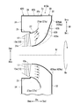
- FIG. 4 is a view corresponding to FIG. 2 in the second embodiment of the present invention.
- FIG. 5 is a view corresponding to FIG. 3 in the first modification of the second embodiment of the present invention.
- the casing 220 of the first steam turbine unit 210a in the second embodiment includes the inner casing 21 and the exhaust casing 225, as in the first embodiment described above.
- the exhaust casing 225 has a diffuser 226 and an outer casing 30.
- the diffuser 226 is disposed on the axial downstream side Dad of the inner casing 21 to bring the first space 21 s into communication with the second space 30 s.
- the diffuser 226 forms an annular diffuser space 226 s directed radially outward gradually toward the axial downstream side Dad.
- the steam that has flowed out from the final moving blade row 13a of the turbine rotor 11 toward the axial downstream side Dad flows into the diffuser space 226s.
- the diffuser 226 has a flow guide 227 that defines the edge of the radially outer Dro of the diffuser space 226s, and a bearing cone 29 that defines the edge of the radially inner Dri of the diffuser space 226s.
- a bearing cone 29 that defines the edge of the radially inner Dri of the diffuser space 226s.
- the flow guide 227 has a tubular shape extending from the end edge of the axial downstream side Dad of the inner casing 21 toward the axial downstream side Dad.
- the flow guide 227 has an annular cross section perpendicular to the axis Ar, and the diameter gradually increases toward the downstream axis Dad.
- the flow guide 227 in the second embodiment is connected to the inner casing 21.
- the flow guide 227 in the second embodiment has a cross-sectional shape including the axis Ar, and is formed in a curved shape that is convex toward the axis Ar. Furthermore, in the second embodiment, the surface length of the flow guide 27 in the cross section including the axis Ar of the flow guide 27 is formed such that the exhaust side Dex is longer than the non-exhaust side Dan. As a result, the angle of the tangent (indicated by a dashed line in FIG. 4) at the end edge 227a is approximately 90 degrees on the exhaust side Dex, while on the non-exhaust side Dan, it is smaller than the exhaust side Dex. It is an angle ( ⁇ sa).
- the flow guide 227 includes a first guide portion 227A on the exhaust side Dex with respect to the axis Ar and a second guide portion 227B on the non-exhaust side Dan with respect to the axis Ar.
- the first guide portion 227A and the second guide portion 227B have an asymmetrical shape.
- the position of the end 227a of the exhaust side Dex in the axial direction Da is disposed on the downstream side Dad of the axis than the position of the end 227a of the non-exhaust side Dan.
- distance R1ex of exhaust side guide end 227aa located most in exhaust side Dex among end edges 227a of flow guide 27, and axis Ar is the anti-exhaust side guide end 227ab located most in the exhaust side Dan.
- the end 227a of the flow guide 227 in this second embodiment is longer on the non-exhaust side Dan than the shortest distance between the axis Ar and the end 227a, and on the exhaust side. It is also shaped like a long oval in Dex.
- the length R1ex in the major axis direction of the oval in the first guide portion 227A is longer than the length R1an in the major axis direction of the second guide portion 227B.
- the distance Rfe between the portion 227A and the axis Ar in the radial direction Dr is larger (Rfa> Rfe).
- the angle ⁇ se of the tangent at the first guide portion 227A at the same position in the axial direction Da as the non-exhaust side guide end 227ab is smaller than the angle ⁇ sa of the tangent at the non-exhaust side guide end 227ab ( ⁇ se ⁇ sa).
- the tangent angle ⁇ sa at the non-exhaust side guide end 227ab is larger than the tangent angle ⁇ se at the first guide portion 227A at the same position in the axial direction Da as the anti-exhaust side guide end 227ab.
- FIG. 4 a comparative example in the case where the second guide portion 227B is formed on the non-exhaust side Dan at the same angle as the flow guide 27 of the first embodiment is indicated by a two-dot chain line. That is, by forming the second guide portion 227B as described above, the dimension of the second guide portion 227B in the axial direction Da becomes shorter than the dimension of the first guide portion 227A in the axial direction Da. Furthermore, the position of the non-exhaust side guide end portion 227ab of the second guide portion 227B can be disposed on the axially upstream side Dau and the radially outer side Dro than the comparative example. In addition, what is shown by the dashed-two dotted line on the axial line upstream Dau of the first guide portion 227A in FIG. 4 is the arrangement of the flow guide 27 in the first embodiment described above.
- the angle of the tangent at the same position in the axial direction Da at the first guide portion 227A is at the boundary position K (see FIG. 5) between the first guide portion 227A and the second guide portion 227B. It is smaller than the angle (not shown) of the tangent of the flow guide 227.
- the diffuser space 226s of the exhaust side Dex In the above, it is possible to suppress the occurrence of peeling on the first guide portion 227A side.
- FIG. 6 is a view corresponding to FIG. 2 in the first modification of the second embodiment of the present invention.
- FIG. 7 is a view corresponding to FIG. 3 in the first modification of the second embodiment of the present invention.
- the casing 220X of the first steam turbine portion 210a in the first modification of the second embodiment has the inner casing 21 and the exhaust casing 225, as in the second embodiment described above. have.
- the exhaust casing 225 has a diffuser 226 and an outer casing 30.
- the diffuser 226 is disposed on the axial downstream side Dad of the inner casing 21 to bring the first space 21 s into communication with the second space 30 s.
- the diffuser 226 forms an annular diffuser space 226 s directed radially outward gradually toward the axial downstream side Dad.
- the steam that has flowed out from the final moving blade row 13a of the turbine rotor 11 toward the axial downstream side Dad flows into the diffuser space 226s.
- the diffuser 226 has a flow guide 227 that defines the edge of the radially outer Dro of the diffuser space 226s, and a bearing cone 29 that defines the edge of the radially inner Dri of the diffuser space 226s.
- the flow guide 227 has a tubular shape extending from the end edge of the axial downstream side Dad of the inner casing 21 toward the axial downstream side Dad.
- the flow guide 227 has an annular cross section perpendicular to the axis Ar, and the diameter gradually increases toward the downstream axis Dad.
- the flow guide 227 in the second embodiment is connected to the inner casing 21.
- the flow guide 227 in the first modified example of the second embodiment has a cross-sectional shape including the axis Ar formed in a curved shape that is convex toward the axis Ar. Furthermore, in the second embodiment, the surface length of the flow guide 27 in the cross section including the axis Ar of the flow guide 27 is formed such that the exhaust side Dex is longer than the non-exhaust side Dan. As a result, the angle of the tangent (indicated by a dashed line in FIG. 6) at the end edge 227a is approximately 90 degrees on the exhaust side Dex, while on the non-exhaust side Dan, it is smaller than the exhaust side Dex. It is an angle.
- the flow guide 227 includes a first guide portion 227AX on the exhaust side Dex with respect to the axis Ar and a second guide portion 227B on the non-exhaust side Dan with respect to the axis Ar.
- the first guide portion 227AX and the second guide portion 227B have an asymmetrical shape.
- the position of the end 227a of the exhaust side Dex in the axial direction Da is disposed on the downstream side Dad of the axis than the position of the end 227a of the non-exhaust side Dan.
- distance R1ex of exhaust side guide end 227aa located most in exhaust side Dex among end edges 227a of flow guide 227, and axis Ar is the anti-exhaust side guide end 227ab located most in the exhaust side Dan.
- the distance R1an from the axis Ar in the radial direction Dr is larger than the distance R1an.
- the end 227a of the flow guide 227 in this second embodiment is longer on the non-exhaust side Dan than the shortest distance between the axis Ar and the end 227a, and on the exhaust side. It is also shaped like a long oval in Dex.
- the length Roe in the major axis direction of the oval in the first guide portion 227AX is longer than the length Roa in the major axis direction of the second guide portion 227B.
- the angle of the tangent (indicated by a dashed line in FIG. 6) of the flow guide 227 at the same position in the axial direction Da is the direction of the exhaust side Dan rather than the exhaust side Dex. Is large.
- the tangent angle ⁇ fe of the first guide portion 227AX is 0 degree or more and smaller than the tangent angle ⁇ fa of the second guide portion 227B ( ⁇ fa> ⁇ fefa0) .
- a comparative example in which the second guide portion 227B is formed on the non-exhaust side Dan at the same angle ⁇ fe as the first guide portion 227AX is indicated by a two-dot chain line. That is, by forming the second guide portion 227B as described above, the dimension of the second guide portion 227B in the axial direction Da becomes shorter than the dimension of the first guide portion 227AX in the axial direction Da. Furthermore, the position of the non-exhaust side guide end portion 227ab of the second guide portion 227B can be disposed on the upstream side Dau in the axial direction and the radially outer side Dro than the comparative example in which the angle ⁇ fe is set. In addition, about the bearing cone 29, since it is the structure similar to 1st, 2nd embodiment, detailed description is abbreviate
- the flow passage cross-sectional area of the non-exhaust side Dan of the diffuser space 226s is smaller than the flow passage cross-sectional area of the exhaust side Dex. Therefore, the flow passage area effective as the diffuser space 226s at the outlet of the diffuser 226 can be expanded to improve the pressure recovery performance of the diffuser 226.
- FIG. 8 is a view corresponding to FIG. 2 in a second modification of the second embodiment of the present invention.
- FIG. 9 is a view corresponding to FIG. 3 in a second modification of the second embodiment of the present invention.
- the first guide portion 227AX is formed to extend to the axial downstream side Dad more than the first guide portion 227A of the second embodiment.
- the bearing cone 229X on the exhaust side Dex is used as the bearing cone 29 on the exhaust side Dex of the second embodiment. It may be formed so as to extend to the axial downstream side Dad (shown by a two-dot chain line in FIG. 8).
- the first cone end 229aa of the exhaust side Dex of the bearing cone 229X may be disposed on the axially downstream side Dau than the second cone end 229ab of the non-exhaust side Dan.
- the position in radial direction Dr of 1st cone end part 229aa in this 2nd modification is the same as the position of radial direction Dr of 1st cone end part 29aa in 1st, 2nd embodiment is illustrated. However, it may be closer to the axis Ar than this position.
- the effective flow passage area of the diffuser 226 can be enlarged on the downstream side Dad of the axis than the first modification. Therefore, the performance of the diffuser 26 can be improved.
- the third embodiment differs from the second embodiment described above in the shapes of the flow guide and the bearing cone on the non-exhaust side Dan. Therefore, while attaching and explaining the same code
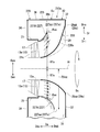
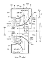
- FIG. 10 is a view corresponding to FIG. 2 in the third embodiment of the present invention.
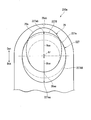
- FIG. 11 is a view corresponding to FIG. 3 in the third embodiment of the present invention.
- the casing 320 of the first steam turbine portion 310a in the third embodiment has the inner casing 21 and the exhaust casing 325, as in the second embodiment described above.
- the exhaust casing 325 has a diffuser 326 and an outer casing 30.
- the diffuser 326 is disposed downstream of the inner casing 21 to bring the first space 21 s into communication with the second space 30 s.
- the diffuser 326 forms an annular diffuser space 326 s directed radially outward gradually toward the axial downstream side Dad.
- the steam that has flowed out from the final moving blade row 13a of the turbine rotor 11 toward the axial downstream side Dad flows into the diffuser space 326s.
- the diffuser 326 has a flow guide 327 defining the edge of the radially outer Dro of the diffuser space 326s, and a bearing cone 329 defining the edge of the radially inner Dri of the diffuser space 326s. Similar to the flow guide 227 of the second embodiment, the flow guide 327 has a tubular shape extending from the end edge of the axial downstream side Dad of the inner casing 21 toward the axial downstream side Dad. The flow guide 327 has an annular cross section perpendicular to the axis Ar, and gradually expands in diameter toward the downstream axis Dad. The flow guide 327 in the third embodiment is also connected to the inner casing 21 as in the second embodiment.
- the flow guide 327 in the third embodiment has a cross-sectional shape including the axis Ar and is formed in a curved shape that is convex toward the axis Ar. Furthermore, in the third embodiment, the length of the arc in the cross section including the axis Ar of the flow guide 327 is formed such that the exhaust side Dex is longer than the non-exhaust side Dan. As a result, the angle of the tangent (indicated by a dashed line in FIG. 10) at the end edge 327a is approximately 90 degrees on the exhaust side Dex, while on the non-exhaust side Dan, it is smaller than the exhaust side Dex It is an angle.
- the flow guide 327 includes a first guide portion 327A on the exhaust side Dex with respect to the axis Ar and a second guide portion 327B on the non-exhaust side Dan with respect to the axis Ar.
- the first guide portion 327A and the second guide portion 327B have an asymmetrical shape.
- the position of the edge 327a of the exhaust side Dex in the axial direction Da is disposed on the upstream side Dau from the position of the edge 327a of the non-exhaust side Dan.
- distance R1ex in radial direction Dr of exhaust side guide end 327aa located in exhaust side Dex among end edges 327a of flow guide 27 and axis Ar is the anti exhaust side guide located in the most anti exhaust side Dan.
- the distance R1an in the radial direction Dr between the end 327ab and the axis Ar is longer (R1ex> R1an).
- an edge 327a of the flow guide 327 in the third embodiment is formed in a long oval shape on the exhaust side Dex and the non-exhaust side Dan when viewed from the axial direction Da.
- the length R1ex in the major axis direction of the first guide portion 327A is longer than the length R1an in the major axis direction of the second guide portion 327B (R1ex> R1an).
- the non-exhaust side guide end 327ab and the axis Ar of the non-exhaust side Dan than the distance R1ex between the exhaust side guide end 327aa of the exhaust side Dex of the flow guide 327 and the axis Ar.
- the distance between R1an is shorter.
- the relationship between the inclination ⁇ fe of the tangent of the first guide portion 327A and the inclination ⁇ fa of the tangent of the second guide 327B at the same position in the axial direction Da is ⁇ fe> ⁇ fa ⁇ It is 0.
- the length Lfa of the second guide portion 327B is longer than the length Lfe of the first guide portion 327A in the axial direction Da of the flow guide 327 (Lfa> Lfe). More specifically, the length of the axial direction Da of the flow guide 327 is formed to be gradually longer from the exhaust side Dex toward the non-exhaust side Dan.
- a comparative example in which the second guide portion 327B is formed on the non-exhaust side Dan at the same angle ⁇ fe as the first guide portion 327A is indicated by a two-dot chain line.
- the bearing cone 329 is formed in a curved shape that is convex toward the axis Ar in the cross section including the axis Ar.
- the edge 329a of the axial downstream side Dad of the bearing cone 329 is between the first cone end 329aa of the exhaust side Dex in the direction perpendicular to the axial line Ar (ie, the diametrical direction about the axial line Ar) and the axial line Ar.
- the distance R2an between the second cone end 329ab on the non-exhaust side Dan and the axis Ar is larger than the distance R2ex in an oval shape.
- the angle between the tangent Ar and the axis Ar in the vicinity of the end 329b of the axis upstream Dau of the bearing cone 329 is the same on the exhaust side Dex and the non-exhaust side Dan. It has become.
- the bearing cone 329 on the non-exhaust side Dan extends from the bearing cone 329 on the exhaust side Dex to the axially downstream side Dad.
- the length La of the bearing cone 329 on the non-exhaust side Dan in the axial direction Da is longer than the length Le of the bearing cone 329 on the exhaust side Dex (La> Le).
- the length of the axial direction Da of the bearing cone 329 is different between the exhaust side Dex and the non-exhaust side Dan, so that the tangent line angle ⁇ oe at the first cone end 329 aa of the exhaust side Dex
- the tangent angle ⁇ oa at the second cone end 329ab is larger ( ⁇ oa> ⁇ oe).
- the length of the bearing cone 329 and the length of the flow guide 327 on the non-exhaust side Dan can be made longer. Therefore, the length of the diffuser space 326s on the non-exhaust side Dan can be increased. As a result, it is possible to suppress the occurrence of backflow in the flow of steam on the bearing cone 329 side, and to improve the pressure recovery performance in the diffuser 326.
- the dimension of the axial direction Da of the exhaust chamber Ec does not increase on the side of the exhaust port 31 where a condenser (not shown) or the like may be arranged, so the degree of freedom of arrangement of the condenser etc. Can be suppressed.
- the fourth embodiment is different from the first embodiment described above in the flow guide centering on the axis. Therefore, while attaching and explaining the same code
- FIG. 12 is a view corresponding to FIG. 2 in the fourth embodiment of the present invention.
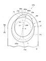
- FIG. 13 is a view corresponding to FIG. 3 in the fourth embodiment of the present invention.
- the casing 420 of the first steam turbine portion 410 a in the fourth embodiment has an inner casing 21 and an exhaust casing 425 as in the first embodiment described above.
- the exhaust casing 425 has a diffuser 426 and an outer casing 30.
- the diffuser 426 is disposed on the axial downstream side Dad of the inner casing 21 and brings the first space 21 s into communication with the second space 30 s.
- the diffuser 426 forms an annular diffuser space 426s which is directed radially outward gradually toward the axial downstream side Dad.
- the steam that has flowed out from the final moving blade row 13a of the turbine rotor 11 toward the axial downstream side Dad flows into the diffuser space 426s.
- the diffuser 426 has a flow guide 27 that defines the edge of the radially outer Dro of the diffuser space 426s, and a bearing cone 429 that defines the edge of the radially inner Dri of the diffuser space 426s.
- the flow guide 27 has the same configuration as the flow guide 27 of the first embodiment, and thus the detailed description thereof will be omitted.
- the bearing cone 429 has a different angle in the circumferential direction Dc with respect to the bearing cone 29 of the first embodiment.
- An edge 429a of the axial downstream side Dad of the bearing cone 429 has an oval shape as viewed from the axial direction Da.
- the second cone end 429 ab of the non-exhaust side Dan at which the distance from the axis Ar is the largest is the most opposite of the edge 429 a of the bearing cone 429. It is disposed at a position shifted forward in the rotational direction of the rotor shaft 12 with respect to the position of the edge portion 429ac of the exhaust side Dan (in other words, the position farthest from the exhaust port 31 in the circumferential direction Dc around the axis Ar) There is.
- the position of the second cone end 429ab is the second cone end
- the rotational direction of the rotor shaft 12 is shifted forward in the circumferential direction Dc than the position of the portion 29ab.
- the first cone end with respect to the imaginary line 27f which is a straight line passing through the exhaust side guide end 27aa, the non-exhaust side guide end 27ab, and the axis Ar of the flow guide 27 when viewed from the axial direction Da.
- the imaginary line 429f passing through the portion 429aa, the second cone end 429ab, and the axis Ar is disposed at a position forward of the rotor shaft 12 in the rotational direction.
- an imaginary line 27f may be a straight line passing through the exhaust side end T1 most to the exhaust side Dex, the non-exhaust side end T2 most to the non-exhaust side Dan, and the axis Ar.
- an angle ⁇ r between the virtual line 27 f and the virtual line 429 f is smaller than 45 degrees and larger than 0 degrees. Furthermore, the angle ⁇ r may be smaller than 30 degrees or smaller than 20 degrees. The angle ⁇ r may be determined, for example, according to the swirl component contained in the flow of the vapor discharged from the first space 21s.
- the distance from the axis Ar to the bearing cone 429 is the largest.
- the two-cone end 429ab can be placed at the position where the reverse flow area is most likely to occur. Therefore, the pressure loss in the diffuser 426 can be effectively reduced.
- the present invention is not limited to the configurations of the above-described embodiments, and design changes can be made without departing from the scope of the invention.
- exhaust chamber of the steam turbine was explained to an example, it is applicable also to exhaust chambers, such as a gas turbine and a turbomachine, for example.
- pressure loss can be reduced to improve performance.
Abstract
排気室(Ec)は、内側ケーシング(21)と、外側ケーシング(30)と、ディフューザ(26)と、を備える。内側ケーシング(21)は、径方向の外側からロータを囲い、ロータとの間に軸線方向(Da)に流体が流れる第一空間(21s)を形成する。ディフューザ(26)は、第一空間(21s)を形成するロータ軸の外周面と連続するように軸線下流側(Dad)に延びる筒状をなし、軸線下流側(Dad)に向かうにしたがって漸次拡径するベアリングコーン(29)を備えている。ベアリングコーン(29)の軸線下流側(Dad)の端縁(29a)は、軸線(Ar)に直交する方向における第一側(Dex)の第一コーン端部(29aa)と軸線(Ar)との間の距離(R2ex)よりも、第二側(Dan)の第二コーン端部(29ab)と軸線(Ar)との間の距離(R2an)の方が大きいオーバル形状を成している。
Description
この発明は、排気室及び蒸気タービンに関する。
本願は、2017年12月28日に日本に出願された特願2017-253815号について優先権を主張し、その内容をここに援用する。
本願は、2017年12月28日に日本に出願された特願2017-253815号について優先権を主張し、その内容をここに援用する。
タービンや圧縮機等の回転機械においては、最終段動翼の下流側に作動流体を圧力回復するためのディフューザを備えている場合が多い。このようなディフューザにおいては、ロータ軸の軸線に沿って排気された作動流体を、例えばレイアウトの都合等により、ロータ軸を中心とした径方向の外側に向けて向きを変更するように形成されたものがある。このようなディフューザは、排気の向きが変更されることで排気損失が大きくなる場合があった。
特許文献1,2には、蒸気タービンの最終段動翼から復水器までの排気損失低減のために、ディフューザのベアリングコーン形状を、外車室の排気側と反排気側とで非対称に形成する技術が提案されている。
特許文献3には、ディフューザのフローガイドを外車室の排気側と反排気側とで非対称に形成する技術が提案されている。
特許文献1,2には、蒸気タービンの最終段動翼から復水器までの排気損失低減のために、ディフューザのベアリングコーン形状を、外車室の排気側と反排気側とで非対称に形成する技術が提案されている。
特許文献3には、ディフューザのフローガイドを外車室の排気側と反排気側とで非対称に形成する技術が提案されている。
しかしながら、特許文献1から3のようにして排気損失を低減させたとしても、反排気側のベアリングコーン付近で逆流が生じたり、排気側のフローガイドで剥離が発生したりして圧力損失が生じる可能性が有る。
この発明は、上記事情に鑑みてなされたものであり、圧力損失を低減して性能向上を図ることができる排気室及び蒸気タービンを提供するものである。
この発明は、上記事情に鑑みてなされたものであり、圧力損失を低減して性能向上を図ることができる排気室及び蒸気タービンを提供するものである。
上記の課題を解決するために以下の構成を採用する。
この発明の第一態様によれば、排気室は、内側ケーシングと、外側ケーシングと、ディフューザと、を備える。内側ケーシングは、ロータ軸の軸線を中心とした径方向の外側からロータを囲い、前記ロータとの間に前記軸線の延びる方向に流体が流れる第一空間を形成する。外側ケーシングは、前記ロータ及び前記内側ケーシングを囲うとともに、前記第一空間を流れた流体が排気される第二空間を前記内側ケーシングとの間に形成し、前記軸線に直交する方向の第一側に出口を有する。ディフューザは、前記内側ケーシングの下流側に配置されて前記第一空間と連通するディフューザ空間を形成し、前記下流側に向かうにつれて径方向外側を向き、前記第一空間と前記第二空間とを連通させる。ディフューザは、前記第一空間を形成する前記ロータ軸の外周面と連続するように軸線方向の下流側に延びる筒状をなし、前記軸線方向の下流側に向かうにしたがって漸次拡径するベアリングコーンを備えている。ベアリングコーンの前記下流側の端縁は、前記軸線に直交する方向における第一側の第一コーン端部と前記軸線との間の距離よりも、前記第一側とは反対側の第二側の第二コーン端部と前記軸線との間の距離の方が大きいオーバル形状を成している。
この第一態様におけるベアリングコーンの下流側の端縁は、軸線に直交する方向における第一側の第一コーン端部と軸線との間の距離よりも、第一側とは反対側の第二側の第二コーン端部と軸線との間の距離の方が大きい。これにより、例えば、第一コーン端部と第二コーン端部とが軸線方向で同じ位置又は、第一コーン端部よりも第二コーン端部が軸線方向における上流側に配置される場合、軸線に対するベアリングコーンの角度は、第一側よりも第二側において大きくなる。そのため、第二側のディフューザ空間においてベアリングコーンを流体の流れに沿わせるように形成できる。一方で、第一コーン端部よりも第二コーン端部が軸線方向で下流側に位置する場合、第二側におけるディフューザ空間の長さを長くできる。そのため、逆流が生じる領域を解消できる。したがって、圧力損失を低減して性能向上を図ることができる。
この発明の第二態様によれば、第一態様に係るディフューザは、前記内側ケーシングの下流側の端縁から前記軸線方向の下流側に延びる筒状をなし、前記軸線方向の下流側に向かうにしたがって漸次拡径するフローガイドを備えていてもよい。前記フローガイドは、前記軸線よりも第一側に形成された第一ガイド部と、前記軸線よりも第二側に形成された第二ガイド部と、を備えていてもよい。前記軸線を含む断面視で、前記第二ガイド部の最も第二側に位置する第二側ガイド端部と前記軸線との径方向における距離は、前記第二側ガイド端部と軸線方向で同一位置の前記第一ガイド部と前記軸線との径方向における距離よりも大きいようにしてもよい。前記第二側ガイド端部における接線と前記軸線とのなす角度は、前記第二側ガイド端部と軸線方向で同一位置の前記第一ガイド部の接線と前記軸線とのなす角度よりも大きいようにしてもよい。
このように構成することで、ディフューザ空間の第二側の流路断面積が第一側の流路断面積よりも減少することを抑制できる。そのため、ディフューザの出口においてディフューザ空間として有効な流路面積を拡大して、ディフューザの圧力回復性能を向上することができる。
このように構成することで、ディフューザ空間の第二側の流路断面積が第一側の流路断面積よりも減少することを抑制できる。そのため、ディフューザの出口においてディフューザ空間として有効な流路面積を拡大して、ディフューザの圧力回復性能を向上することができる。
この発明の第三態様によれば、第一態様に係るディフューザは、前記内側ケーシングの下流側の端縁から前記軸線方向の下流側に延びる筒状をなし、前記軸線方向の下流側に向かうにしたがって漸次拡径するフローガイドを備えていてもよい。前記フローガイドは、前記軸線よりも第一側に形成された第一ガイド部と、前記軸線よりも第二側に形成された第二ガイド部と、を備えていてもよい。軸線を含む断面視で、前記第二ガイド部の接線と前記軸線とのなす角度は、前記第二ガイド部の接線と前記軸線方向で同一位置の前記第一ガイド部の接線と前記軸線とのなす角度よりも大きいようにしてもよい。
このように構成することで、ディフューザ空間の第二側の流路断面積が第一側の流路断面積よりも減少することを抑制できる。そのため、ディフューザの出口においてディフューザ空間として有効な流路面積を拡大して、ディフューザの圧力回復性能を向上することができる。
このように構成することで、ディフューザ空間の第二側の流路断面積が第一側の流路断面積よりも減少することを抑制できる。そのため、ディフューザの出口においてディフューザ空間として有効な流路面積を拡大して、ディフューザの圧力回復性能を向上することができる。
この発明の第四態様によれば、第二又は第三態様に係る第一側の第一コーン端部は、前記第二側の第二コーン端部よりも、前記軸線方向の下流側に位置していてもよい。
第一側のディフューザ空間においては、内側ケーシングの内側の第一空間から排出された流体の流れが軸線方向を向いているため、ベアリングコーン側で剥離が生じ難い。そのため、第一側の第一コーン端部を、第二側の第二コーン端部よりも、軸線方向の下流側に位置することで、第一側におけるディフューザ空間として有効な流路断面積を拡大することができる。
第一側のディフューザ空間においては、内側ケーシングの内側の第一空間から排出された流体の流れが軸線方向を向いているため、ベアリングコーン側で剥離が生じ難い。そのため、第一側の第一コーン端部を、第二側の第二コーン端部よりも、軸線方向の下流側に位置することで、第一側におけるディフューザ空間として有効な流路断面積を拡大することができる。
この発明の第五態様によれば、第一態様に係るディフューザは、前記内側ケーシングの下流側の端縁から前記軸線方向の下流側に延びる筒状をなし、前記軸線方向の下流側に向かうにしたがって漸次拡径するフローガイドを備えていてもよい。前記フローガイドは、前記軸線よりも第一側に形成された第一ガイド部と、前記軸線よりも第二側に形成された第二ガイド部と、を備えていてもよい。前記第二コーン端部は、前記第一コーン端部よりも軸線方向の下流側に配置されてもよい。さらに、第一態様に係る第二ガイド部は、前記第一ガイド部よりも軸線方向の長さが長いようにしてもよい。
このように構成することで、第二側におけるベアリングコーンの長さとフローガイドの長さとをそれぞれ長くすることができるため、第二側におけるディフューザ空間の長さを、長くすることができる。そのため、ベアリングコーン側に逆流が発生することを抑制して、ディフューザにおける圧力回復性能を向上することができる。
このように構成することで、第二側におけるベアリングコーンの長さとフローガイドの長さとをそれぞれ長くすることができるため、第二側におけるディフューザ空間の長さを、長くすることができる。そのため、ベアリングコーン側に逆流が発生することを抑制して、ディフューザにおける圧力回復性能を向上することができる。
この発明の第六態様によれば、第一態様に係るベアリングコーンのうち、前記軸線からの距離が最も大きい端部は、前記軸線を中心とした周方向における最も第二側の位置よりも、前記ロータ軸の回転方向における前方にずれた位置に配置されていてもよい。
このように構成することで、例えば、ロータの最終段動翼から旋回成分を含む流れがディフューザに流入した場合に、ベアリングコーンのうち軸線からの距離が最も大きい端部を、逆流領域が最も生じ易い位置に配置することができる。したがって、ディフューザにおける圧力損失を有効に低減することができる。
このように構成することで、例えば、ロータの最終段動翼から旋回成分を含む流れがディフューザに流入した場合に、ベアリングコーンのうち軸線からの距離が最も大きい端部を、逆流領域が最も生じ易い位置に配置することができる。したがって、ディフューザにおける圧力損失を有効に低減することができる。
この発明の第七態様によれば、蒸気タービンは、第一から第六態様の何れか一つの態様に係る排気室を備える。
このように構成することで、蒸気タービンの効率向上を図ることができる。
このように構成することで、蒸気タービンの効率向上を図ることができる。
上記排気室及び蒸気タービンによれば、圧力損失を低減して性能向上を図ることができる。
次に、この発明の実施形態における排気室及び蒸気タービンを図面に基づき説明する。
(第一実施形態)
図1は、この発明の第一実施形態における蒸気タービンの概略構成を示す図である。
図1に示すように、この第一実施形態の蒸気タービンSTは、二分流排気型の蒸気タービンである。この蒸気タービンSTは、第一蒸気タービン部10aと第二蒸気タービン部10bとを備えている。第一蒸気タービン部10a及び第二蒸気タービン部10bは、いずれも、軸線Arを中心として回転するタービンロータ(ロータ)11と、タービンロータ11を覆うケーシング20と、ケーシング20に固定されている複数の静翼列17と、蒸気流入管19と、を備えている。以下の説明において、軸線Arを中心とした周方向を単に周方向Dcとし、軸線Arに対して垂直な方向を径方向Drとする。さらに、径方向Drで軸線Arの側を径方向内側Dri、その反対側を径方向外側Droとする。
第一蒸気タービン部10aと第二蒸気タービン部10bとは、蒸気流入管19を共有する。第一蒸気タービン部10aは、この蒸気流入管19を除き、この蒸気流入管19を基準にして軸線方向Daの一方側に配置されている。第二蒸気タービン部10bは、この蒸気流入管19を除き、この蒸気流入管19を基準にして軸線方向Daの他方側に配置されている。ここで、第一蒸気タービン部10aの構成と第二蒸気タービン部10bの構成とは、基本的に同一である。そのため、以下の説明では、主に第一蒸気タービン部10aについて説明し、第二蒸気タービン部10bの説明を省略する。第一蒸気タービン部10aにおいて、軸線方向Daの蒸気流入管19の側を軸線上流側Dau、その反対側を軸線下流側Dadとする。
タービンロータ11は、軸線Arを中心として軸線方向Daに延びるロータ軸12と、このロータ軸12に取り付けられている複数の動翼列13と、を有する。タービンロータ11は、軸線Arを中心として回転可能に軸受18で支持されている。複数の動翼列13は、軸線方向Daに並んでいる。複数の動翼列13は、いずれも、周方向Dcに並んでいる複数の動翼で構成される。第一蒸気タービン部10aのタービンロータ11と、第二蒸気タービン部10bのタービンロータ11とは、同一の軸線Ar上に位置して互いに連結されて、軸線Arを中心として一体回転する。
ケーシング20は、内側ケーシング21と、排気ケーシング25とを有する。
内側ケーシング21は、ロータ軸12との間に、軸線Arを中心とした環状をなす第一空間21sを形成する。蒸気流入管19から流入した蒸気(流体)は、この第一空間21sを軸線方向Daに(より具体的には軸線下流側Dadに向かって)流れる。タービンロータ11の複数の動翼列13は、この第一空間21s内に配置されている。複数の静翼列17は、軸線方向Daに並んで、この第一空間21s内に配置されている。複数の静翼列17のそれぞれは、複数の動翼列13のうちいずれか一つの動翼列13の軸線上流側Dauに配置されている。複数の静翼列17は、内側ケーシング21に固定されている。
内側ケーシング21は、ロータ軸12との間に、軸線Arを中心とした環状をなす第一空間21sを形成する。蒸気流入管19から流入した蒸気(流体)は、この第一空間21sを軸線方向Daに(より具体的には軸線下流側Dadに向かって)流れる。タービンロータ11の複数の動翼列13は、この第一空間21s内に配置されている。複数の静翼列17は、軸線方向Daに並んで、この第一空間21s内に配置されている。複数の静翼列17のそれぞれは、複数の動翼列13のうちいずれか一つの動翼列13の軸線上流側Dauに配置されている。複数の静翼列17は、内側ケーシング21に固定されている。
排気ケーシング25は、ディフューザ26と、外側ケーシング30とを有する。
外側ケーシング30は、タービンロータ11及び内側ケーシング21を囲うとともに、第一空間21sを流れた蒸気が排出される第二空間30sを内側ケーシング21との間に形成する。この第二空間30sは、ディフューザ26に連通し、ディフューザ26の外周側を周方向Dcに広がる。この外側ケーシング30は、ディフューザ空間26sから第二空間30sに流入した蒸気を排気口31に導く。
外側ケーシング30は、タービンロータ11及び内側ケーシング21を囲うとともに、第一空間21sを流れた蒸気が排出される第二空間30sを内側ケーシング21との間に形成する。この第二空間30sは、ディフューザ26に連通し、ディフューザ26の外周側を周方向Dcに広がる。この外側ケーシング30は、ディフューザ空間26sから第二空間30sに流入した蒸気を排気口31に導く。
外側ケーシング30は、軸線Arに直交する方向の第一側(図1において下側)に排気口(出口)31を有する。この実施形態で例示する外側ケーシング30は、鉛直下方向に向かって開口している。この実施形態の蒸気タービンSTは、いわゆる下方排気型の復水蒸気タービンであり、排気口31には、蒸気を水に戻す復水器(図示せず)が接続されている。この実施形態における外側ケーシング30は、下流側端板32と、上流側端板34と、側周板36と、をそれぞれ備えている。
下流側端板32は、ベアリングコーン29の径方向外側Droの縁から径方向外側Droに広がって、第二空間30sの軸線下流側Dadの縁を画定する。
上流側端板34は、ディフューザ26よりも軸線上流側Dauに配置されている。この上流側端板34は、内側ケーシング21の外周面21oから径方向外側Droに広がって、第二空間30sの軸線上流側Dauの縁を画定する。
側周板36は、下流側端板32及び上流側端板34に接続され、軸線方向Daに広がり且つ軸線Arを中心として周方向Dcに広がって、第二空間30sの径方向外側Droの縁を画定する。
上流側端板34は、ディフューザ26よりも軸線上流側Dauに配置されている。この上流側端板34は、内側ケーシング21の外周面21oから径方向外側Droに広がって、第二空間30sの軸線上流側Dauの縁を画定する。
側周板36は、下流側端板32及び上流側端板34に接続され、軸線方向Daに広がり且つ軸線Arを中心として周方向Dcに広がって、第二空間30sの径方向外側Droの縁を画定する。
ディフューザ26は、内側ケーシング21の軸線下流側Dadに配置されて、第一空間21sと第二空間30sとを連通させる。このディフューザ26は、軸線下流側Dadに向うに連れて次第に径方向外側に向かう環状のディフューザ空間26sを形成する。ディフューザ空間26s内には、タービンロータ11の最終動翼列13aから軸線下流側Dadに向かって流出した蒸気が流入する。ここで、最終動翼列13aとは、第一蒸気タービン部10aが備える複数の動翼列13のうち、最も軸線下流側Dadに配置されている動翼列13である。
ディフューザ26は、ディフューザ空間26sの径方向外側Droの縁を画定するフローガイド(又は、スチームガイド、外側ディフューザともいう)27と、ディフューザ空間26sの径方向内側Driの縁を画定するベアリングコーン(又は、内側ディフューザともいう)29と、を有する。
ベアリングコーン29は、第一空間21sを形成するロータ軸12の外周面12aと連続するように軸線下流側Dadに延びる筒状に形成されている。ベアリングコーン29は、軸線Arに対して垂直な断面が環状を成し、軸線下流側Dadに向うにしたがって径方向外側Droに向かって漸次拡径している。ベアリングコーン29の端縁29aは、外側ケーシング30の下流側端板32に接続されている。
フローガイド27は、内側ケーシング21の軸線下流側Dadの端縁から軸線下流側Dadに向かって延びる筒状をなしている。フローガイド27は、軸線Arに対して垂直な断面が環状を成し、軸線下流側Dadに向かうにしたがって漸次拡径している。この実施形態におけるフローガイド27は、内側ケーシング21に接続されている。
この発明における排気室Ecは、内側ケーシング21と外側ケーシング30とディフューザ26とにより構成されている。
この発明における排気室Ecは、内側ケーシング21と外側ケーシング30とディフューザ26とにより構成されている。
図2は、この発明の第一実施形態における排気室の拡大図である。図3は、この発明の第一実施形態における軸線方向から見たベアリングコーンとフローガイドの外形を示す図である。
ここで、図2に示すように、排気口31が軸線Arに直交する方向の一方(第一側)にのみ配置されることで排気室Ecは周方向Dcで非対称形状となり、周方向に圧力分布が生じる。そして、図2に示すように、排気口31が配置される側とは反対側(第二側)において、第一空間21sから排出される蒸気の流れが径方向外側Droを向いて流量分布(図2において、ディフューザ26内部に二点鎖線及び矢印で示す)がフローガイド27側に偏ってしまう。以下の説明において、軸線Arよりも排気口31が形成されている軸線Arに直交する方向の第一側を排気側Dex、軸線Arを挟んでこの排気口31とは反対側を反排気側Danという(第二実施形態以降も同様)。
ここで、図2に示すように、排気口31が軸線Arに直交する方向の一方(第一側)にのみ配置されることで排気室Ecは周方向Dcで非対称形状となり、周方向に圧力分布が生じる。そして、図2に示すように、排気口31が配置される側とは反対側(第二側)において、第一空間21sから排出される蒸気の流れが径方向外側Droを向いて流量分布(図2において、ディフューザ26内部に二点鎖線及び矢印で示す)がフローガイド27側に偏ってしまう。以下の説明において、軸線Arよりも排気口31が形成されている軸線Arに直交する方向の第一側を排気側Dex、軸線Arを挟んでこの排気口31とは反対側を反排気側Danという(第二実施形態以降も同様)。
この第一実施形態におけるフローガイド27は、軸線Arを含む仮想平面による断面(以下、軸線Arを含む断面という)の形状が、軸線Ar側に凸となる曲面状に形成されている。
さらに、この第一実施形態において、フローガイド27の軸線Arを含む断面におけるフローガイド27の表面長さは、反排気側Danよりも排気側Dexの方が長くなるように形成されている。これにより、端縁27aにおける接線(図2中、鎖線で示す)と軸線Arとのなす角度は、排気側Dexにおいては、ほぼ90度となるのに対して、反排気側Danにおいては、排気側Dexよりも小さい角度となっている。
軸線方向Daにおける排気側Dexの端縁27aの位置は、反排気側Danの端縁27aの位置よりも軸線下流側Dadに配置されている。そして、フローガイド27の端縁27aのうち、最も排気側Dexに位置する排気側ガイド端部27aaと軸線Arとの間の距離R1exは、最も反排気側Danに位置する反排気側ガイド端部27abと軸線Arとの間の距離R1anよりも長くなっている。
図3に示すように、この第一実施形態におけるフローガイド27の端縁27aは、軸線Arよりも反排気側Danの半部において半円状に形成され、軸線Arよりも排気側Dexの半部において、反排気側Danの半部の半円の半径(図3中、二点鎖線で示す位置)よりも排気側Dexに長い。つまり、フローガイド27の端縁27aは、軸線方向Daから見て反排気側Danから排気側exに向かって長いオーバル状になっている。なお、軸線方向Daから見て、フローガイド27の端縁27aがオーバル状に形成されて、排気側Dexと反排気側Danとで非対称に形成される場合について説明した。しかし、軸線方向Daから見て、フローガイド27の端縁27aが円形に形成されてもよい。また、フローガイド27は、排気側Dexと反排気側Danで対称に形成されていても良い。
図2に示すように、軸線Arを含む断面において、ベアリングコーン29は、軸線Ar側に凸となる曲面状に形成されている。このベアリングコーン29の端縁29aの軸線方向Daの位置は、周方向Dcの全周で同一位置となっている。ベアリングコーン29の軸線下流側Dadの端縁29aは、軸線方向Daから見て、軸線Arに直交する方向(すなわち、軸線Arを中心とした直径方向)における、排気側Dexの第一コーン端部29aaと軸線Arとの間の距離R2exよりも、反排気側Danの第二コーン端部29abと軸線Arとの間の距離R2anの方が大きいオーバル形状を成している。
軸線方向Daの同一位置において、ベアリングコーン29の軸線上流側Dauの端縁29b付近における接線(図2中、鎖線で示す)と軸線Arとの角度は、排気側Dexよりも反排気側Danの方が大きくなっている。具体的には、軸線上流側Dauの端縁29bのうち、排気側Dexの端部29baにおける接線と軸線Arとの角度θeは、θe≧0となる。また、軸線上流側Dauの端縁29bのうち、反排気側Danの端部29bbにおける接線と軸線Arとの角度θaは、θa>θe≧0となっている。なお、以下、接線と軸線Arとの角度は、単に接線の角度という。
ベアリングコーン29の端縁29aにおける接線(図2中、鎖線で示す)の角度は、排気側Dexの第一コーン端部29aaにおける接線の角度θoeよりも、反排気側Danの第二コーン端部29abにおける接線の角度θoaの方が大きくなっている(θoa>θoe)。図2において、角度θoa,θoeは、それぞれ軸線Arと平行な仮想線(図2中、鎖線で示す)に対する角度として示している(第二実施形態以降も同様)。
ここで、図2の反排気側Dan(図2において上側)において、ベアリングコーン29よりも軸線下流側Dadに示す二点鎖線は、軸線Arを中心とした周方向Dcの全周で、排気側Dexにおけるベアリングコーン29の形状を採用した場合(比較例)を示している。つまり、上述した第一実施形態では、反排気側Danにおけるベアリングコーン29の位置が比較例よりも軸線上流側Dauに移動することとなる。
上述した第一実施形態によれば、ベアリングコーンの軸線下流側Dadの端縁29aは、排気側Dexの第一コーン端部29aaと軸線Arとの間の距離R2exよりも、反排気側Danの第二コーン端部29abと軸線Arとの間の距離R2anの方が大きい。これにより、例えば、第一コーン端部29aaと第二コーン端部29abとが軸線方向Daで同じ位置に配置される場合、軸線Arに対するベアリングコーン29の接線の角度は、排気側Dexの接線の角度θeよりも反排気側Danの接線の角度θaの方が大きくなる。そのため、反排気側Dan側のディフューザ空間26sにおいてベアリングコーン29を蒸気の流れに沿わせるように形成できる。そのため、反排気側Danにおいて逆流が生じる領域を解消できる。その結果、ディフューザ26における圧力損失を低減して性能向上を図ることができる。
(第二実施形態)
次に、この発明の第二実施形態を図面に基づき説明する。この第二実施形態は、上述した第一実施形態と、反排気側Danにおけるフローガイドの形状及び排気側Dexにおけるフローガイドの形状が異なる。そのため、上述した第一実施形態と同一部分に同一符号を付して説明するとともに、重複する説明を省略する。
次に、この発明の第二実施形態を図面に基づき説明する。この第二実施形態は、上述した第一実施形態と、反排気側Danにおけるフローガイドの形状及び排気側Dexにおけるフローガイドの形状が異なる。そのため、上述した第一実施形態と同一部分に同一符号を付して説明するとともに、重複する説明を省略する。
図4は、この発明の第二実施形態における図2に相当する図である。図5は、この発明の第二実施形態の第一変形例における図3に相当する図である。
図4、図5に示すように、この第二実施形態における第一蒸気タービン部210aのケーシング220は、上述した第一実施形態と同様に、内側ケーシング21と排気ケーシング225とを有している。排気ケーシング225は、ディフューザ226と、外側ケーシング30とを有している。
図4、図5に示すように、この第二実施形態における第一蒸気タービン部210aのケーシング220は、上述した第一実施形態と同様に、内側ケーシング21と排気ケーシング225とを有している。排気ケーシング225は、ディフューザ226と、外側ケーシング30とを有している。
ディフューザ226は、内側ケーシング21の軸線下流側Dadに配置されて、第一空間21sと第二空間30sとを連通させる。このディフューザ226は、軸線下流側Dadに向うに連れて次第に径方向外側に向かう環状のディフューザ空間226sを形成する。ディフューザ空間226s内には、タービンロータ11の最終動翼列13aから軸線下流側Dadに向かって流出した蒸気が流入する。
ディフューザ226は、ディフューザ空間226sの径方向外側Droの縁を画定するフローガイド227と、ディフューザ空間226sの径方向内側Driの縁を画定するベアリングコーン29と、を有する。なお、ベアリングコーン29については、第一実施形態と同様の構成であるため、詳細説明を省略する。
フローガイド227は、内側ケーシング21の軸線下流側Dadの端縁から軸線下流側Dadに向かって延びる筒状をなしている。フローガイド227は、軸線Arに対して垂直な断面が環状を成し、軸線下流側Dadに向かうにしたがって漸次拡径している。この第二実施形態におけるフローガイド227は、内側ケーシング21に接続されている。ここで、フローガイド227と内側ケーシング21との接続(又は組立)を容易にするために、フローガイド227と内側ケーシング21との間に、フローガイド227と一体に形成された、軸線方向Daに延びる円筒状の部分が存在する場合がある。この円筒状の部分はディフューザ226として機能しないため、フローガイド227には含まれない(各実施形態及び各変形例も同様)。
この第二実施形態におけるフローガイド227は、第一実施形態と同様に、軸線Arを含む断面形状が、軸線Ar側に凸となる曲面状に形成されている。さらに、この第二実施形態において、フローガイド27の軸線Arを含む断面におけるフローガイド27の表面長さは、反排気側Danよりも排気側Dexが長くなるように形成されている。これにより、端縁227aにおける接線(図4中、鎖線で示す)の角度は、排気側Dexにおいては、ほぼ90度となるのに対して、反排気側Danにおいては、排気側Dexよりも小さい角度(θsa)となっている。
フローガイド227は、軸線Arよりも排気側Dexに第一ガイド部227Aを備え、軸線Arよりも反排気側Danに第二ガイド部227Bを備える。これら第一ガイド部227Aと第二ガイド部227Bとは、非対称形状となっている。
軸線方向Daにおける排気側Dexの端縁227aの位置は、反排気側Danの端縁227aの位置よりも軸線下流側Dadに配置されている。そして、フローガイド27の端縁227aのうち、最も排気側Dexに位置する排気側ガイド端部227aaと軸線Arとの距離R1exは、最も反排気側Danに位置する反排気側ガイド端部227abと軸線Arとの径方向Drにおける距離Rfa(=R1an)よりも大きくなっている。
図5に示すように、この第二実施形態におけるフローガイド227の端縁227aは、軸線Arと端縁227aとの間が最短となる距離よりも、反排気側Danに長く、また、排気側Dexにも長いオーバル状に形成されている。第一ガイド部227Aにおけるオーバルの長径方向の長さR1exは、第二ガイド部227Bのオーバルの長径方向の長さR1anよりも長く形成されている。
最も反排気側Danに位置する反排気側ガイド端部227abと軸線Arとの径方向Drにおける距離Rfa(=R1an)は、反排気側ガイド端部227abと軸線方向Daで同一位置の第一ガイド部227Aと軸線Arとの径方向Drにおける距離Rfeよりも大きい(Rfa>Rfe)。そして、反排気側ガイド端部227abと軸線方向Daで同一位置の第一ガイド部227Aにおける接線の角度θseは、反排気側ガイド端部227abにおける接線の角度θsaよりも小さい(θse<θsa)。言い換えれば、反排気側ガイド端部227abにおける接線の角度θsaは、反排気側ガイド端部227abと軸線方向Daで同一位置の第一ガイド部227Aにおける接線の角度θseよりも大きい。
ここで、図4では、反排気側Danに第一実施形態のフローガイド27と同様の角度で第二ガイド部227Bを形成した場合の比較例を二点鎖線で示している。つまり、上記のように第二ガイド部227Bを形成することで、第二ガイド部227Bの軸線方向Daの寸法が、第一ガイド部227Aの軸線方向Daの寸法よりも短くなる。さらに、第二ガイド部227Bの反排気側ガイド端部227abの位置を、比較例よりも軸線上流側Dau且つ径方向外側Droに配置することができる。なお、図4において第一ガイド部227Aの軸線上流側Dauに二点鎖線で示すのは、上述した第一実施形態におけるフローガイド27の配置である。
このようにすることで、軸線方向Daの同一位置における接線の角度は、第一ガイド部227Aの方が、第一ガイド部227Aと第二ガイド部227Bとの境界位置K(図5参照)におけるフローガイド227の接線の角度(図示せず)よりも小さくなる。
したがって、この第二実施形態によれば、第二ガイド部227Bよりも、第一ガイド部227Aが軸線下流側Dadまで延びて、蒸気の流れに沿うようになるため、排気側Dexのディフューザ空間226sにおいて、第一ガイド部227A側に剥離が生じることを抑制できる。
(第二実施形態の第一変形例)
次に、この発明の第二実施形態の第一変形例を図面に基づき説明する。上述した第二実施形態と同一部分に同一符号を付して説明するとともに、重複する説明を省略する。
次に、この発明の第二実施形態の第一変形例を図面に基づき説明する。上述した第二実施形態と同一部分に同一符号を付して説明するとともに、重複する説明を省略する。
図6は、この発明の第二実施形態の第一変形例における図2に相当する図である。図7は、この発明の第二実施形態の第一変形例における図3に相当する図である。
図6、図7に示すように、この第二実施形態の第一変形例における第一蒸気タービン部210aのケーシング220Xは、上述した第二実施形態と同様に、内側ケーシング21と排気ケーシング225とを有している。排気ケーシング225は、ディフューザ226と、外側ケーシング30とを有している。
図6、図7に示すように、この第二実施形態の第一変形例における第一蒸気タービン部210aのケーシング220Xは、上述した第二実施形態と同様に、内側ケーシング21と排気ケーシング225とを有している。排気ケーシング225は、ディフューザ226と、外側ケーシング30とを有している。
ディフューザ226は、内側ケーシング21の軸線下流側Dadに配置されて、第一空間21sと第二空間30sとを連通させる。このディフューザ226は、軸線下流側Dadに向うに連れて次第に径方向外側に向かう環状のディフューザ空間226sを形成する。ディフューザ空間226s内には、タービンロータ11の最終動翼列13aから軸線下流側Dadに向かって流出した蒸気が流入する。
ディフューザ226は、ディフューザ空間226sの径方向外側Droの縁を画定するフローガイド227と、ディフューザ空間226sの径方向内側Driの縁を画定するベアリングコーン29と、を有する。
フローガイド227は、内側ケーシング21の軸線下流側Dadの端縁から軸線下流側Dadに向かって延びる筒状をなしている。フローガイド227は、軸線Arに対して垂直な断面が環状を成し、軸線下流側Dadに向かうにしたがって漸次拡径している。この第二実施形態におけるフローガイド227は、内側ケーシング21に接続されている。
この第二実施形態の第一変形例におけるフローガイド227は、第一、第二実施形態と同様に、軸線Arを含む断面形状が、軸線Ar側に凸となる曲面状に形成されている。さらに、この第二実施形態において、フローガイド27の軸線Arを含む断面におけるフローガイド27の表面長さは、反排気側Danよりも排気側Dexが長くなるように形成されている。これにより、端縁227aにおける接線(図6中、鎖線で示す)の角度は、排気側Dexにおいては、ほぼ90度となるのに対して、反排気側Danにおいては、排気側Dexよりも小さい角度となっている。
フローガイド227は、軸線Arよりも排気側Dexに第一ガイド部227AXを備え、軸線Arよりも反排気側Danに第二ガイド部227Bを備える。これら第一ガイド部227AXと第二ガイド部227Bとは、非対称形状となっている。
軸線方向Daにおける排気側Dexの端縁227aの位置は、反排気側Danの端縁227aの位置よりも軸線下流側Dadに配置されている。そして、フローガイド227の端縁227aのうち、最も排気側Dexに位置する排気側ガイド端部227aaと軸線Arとの距離R1exは、最も反排気側Danに位置する反排気側ガイド端部227abと軸線Arとの径方向Drにおける距離R1anよりも大きくなっている。
図7に示すように、この第二実施形態におけるフローガイド227の端縁227aは、軸線Arと端縁227aとの間が最短となる距離よりも、反排気側Danに長く、また、排気側Dexにも長いオーバル状に形成されている。第一ガイド部227AXにおけるオーバルの長径方向の長さRoeは、第二ガイド部227Bのオーバルの長径方向の長さRoaよりも長く形成されている。
図6に示すように、軸線Arを含む断面において、軸線方向Daの同一位置におけるフローガイド227の接線(図6中、鎖線で示す)の角度は、排気側Dexよりも反排気側Danの方が大きい。具体的には、軸線方向Daの同一位置において、第一ガイド部227AXの接線の角度θfeは0度以上で且つ、第二ガイド部227Bの接線の角度θfaよりも小さい(θfa>θfe≧0)。ここで、図6では、反排気側Danに第一ガイド部227AXと同様の角度θfeで第二ガイド部227Bを形成した場合の比較例を二点鎖線で示している。つまり、上記のように第二ガイド部227Bを形成することで、第二ガイド部227Bの軸線方向Daの寸法が、第一ガイド部227AXの軸線方向Daの寸法よりも短くなる。さらに、第二ガイド部227Bの反排気側ガイド端部227abの位置を、角度θfeとした比較例よりも軸線上流側Dau且つ径方向外側Droに配置することができる。
なお、ベアリングコーン29については、第一、第二実施形態と同様の構成であるため、詳細説明を省略する。
なお、ベアリングコーン29については、第一、第二実施形態と同様の構成であるため、詳細説明を省略する。
したがって、上述した第二実施形態の第一変形例によれば、ディフューザ空間226sの反排気側Danの流路断面積が排気側Dexの流路断面積よりも減少することを抑制できる。そのため、ディフューザ226の出口においてディフューザ空間226sとして有効な流路面積を拡大して、ディフューザ226の圧力回復性能を向上することができる。
(第二実施形態の第二変形例)
図8は、この発明の第二実施形態の第二変形例における図2に相当する図である。図9は、この発明の第二実施形態の第二変形例における図3に相当する図である。
上述した第二実施形態の第一変形例においては、第一ガイド部227AXを、第二実施形態の第一ガイド部227Aよりも軸線下流側Dadまで延びるように形成した。この第一変形例のフローガイド227と同様、例えば、図8、図9に示す第二変形例のように、排気側Dexにおけるベアリングコーン229Xを、第二実施形態の排気側Dexにおけるベアリングコーン29(図8中、二点鎖線で示す)よりも軸線下流側Dadまで延びるように形成しても良い。
図8は、この発明の第二実施形態の第二変形例における図2に相当する図である。図9は、この発明の第二実施形態の第二変形例における図3に相当する図である。
上述した第二実施形態の第一変形例においては、第一ガイド部227AXを、第二実施形態の第一ガイド部227Aよりも軸線下流側Dadまで延びるように形成した。この第一変形例のフローガイド227と同様、例えば、図8、図9に示す第二変形例のように、排気側Dexにおけるベアリングコーン229Xを、第二実施形態の排気側Dexにおけるベアリングコーン29(図8中、二点鎖線で示す)よりも軸線下流側Dadまで延びるように形成しても良い。
言い換えれば、ベアリングコーン229Xの排気側Dexの第一コーン端部229aaは、反排気側Danの第二コーン端部229abよりも軸線下流側Dauに配置されるようにしても良い。なお、この第二変形例における第一コーン端部229aaの径方向Drにおける位置は、第一、第二実施形態における第一コーン端部29aaの径方向Drの位置と同じである場合を例示しているが、この位置よりも軸線Arに近い側であっても良い。
したがって、第二実施形態の第二変形例によれば、ディフューザ226の排気側Dexにおいて、第一変形例よりも軸線下流側Dadにディフューザ226の有効な流路面積を拡大することができる。そのため、ディフューザ26の性能を向上できる。
(第三実施形態)
次に、この発明の第三実施形態を図面に基づき説明する。この第三実施形態は、上述した第二実施形態と、反排気側Danにおけるフローガイド及びベアリングコーンの形状が異なる。そのため、上述した第二実施形態と同一部分に同一符号を付して説明するとともに、重複する説明を省略する。
次に、この発明の第三実施形態を図面に基づき説明する。この第三実施形態は、上述した第二実施形態と、反排気側Danにおけるフローガイド及びベアリングコーンの形状が異なる。そのため、上述した第二実施形態と同一部分に同一符号を付して説明するとともに、重複する説明を省略する。
図10は、この発明の第三実施形態における図2に相当する図である。図11は、この発明の第三実施形態における図3に相当する図である。
図10、図11に示すように、この第三実施形態における第一蒸気タービン部310aのケーシング320は、上述した第二実施形態と同様に、内側ケーシング21と排気ケーシング325とを有している。さらに、排気ケーシング325は、ディフューザ326と、外側ケーシング30とを有している。
図10、図11に示すように、この第三実施形態における第一蒸気タービン部310aのケーシング320は、上述した第二実施形態と同様に、内側ケーシング21と排気ケーシング325とを有している。さらに、排気ケーシング325は、ディフューザ326と、外側ケーシング30とを有している。
ディフューザ326は、内側ケーシング21の下流側に配置されて、第一空間21sと第二空間30sとを連通させる。このディフューザ326は、軸線下流側Dadに向うに連れて次第に径方向外側に向かう環状のディフューザ空間326sを形成する。ディフューザ空間326s内には、タービンロータ11の最終動翼列13aから軸線下流側Dadに向かって流出した蒸気が流入する。
ディフューザ326は、ディフューザ空間326sの径方向外側Droの縁を画定するフローガイド327と、ディフューザ空間326sの径方向内側Driの縁を画定するベアリングコーン329と、を有する。
フローガイド327は、第二実施形態のフローガイド227と同様に、内側ケーシング21の軸線下流側Dadの端縁から軸線下流側Dadに向かって延びる筒状をなしている。フローガイド327は、軸線Arに対して垂直な断面が環状を成し、軸線下流側Dadに向かうにしたがって漸次拡径している。この第三実施形態におけるフローガイド327も、第二実施形態と同様に、内側ケーシング21に接続されている。
フローガイド327は、第二実施形態のフローガイド227と同様に、内側ケーシング21の軸線下流側Dadの端縁から軸線下流側Dadに向かって延びる筒状をなしている。フローガイド327は、軸線Arに対して垂直な断面が環状を成し、軸線下流側Dadに向かうにしたがって漸次拡径している。この第三実施形態におけるフローガイド327も、第二実施形態と同様に、内側ケーシング21に接続されている。
この第三実施形態におけるフローガイド327は、第二実施形態と同様に、軸線Arを含む断面形状が、軸線Ar側に凸となる曲面状に形成されている。さらに、この第三実施形態において、フローガイド327の軸線Arを含む断面における円弧の長さは、反排気側Danよりも排気側Dexが長くなるように形成されている。これにより、端縁327aにおける接線(図10中、鎖線で示す)の角度は、排気側Dexにおいては、ほぼ90度となるのに対して、反排気側Danにおいては、排気側Dexよりも小さい角度となっている。
フローガイド327は、軸線Arよりも排気側Dexに第一ガイド部327Aを備え、軸線Arよりも反排気側Danに第二ガイド部327Bを備える。これら第一ガイド部327Aと第二ガイド部327Bとは、非対称形状となっている。
軸線方向Daにおける排気側Dexの端縁327aの位置は、反排気側Danの端縁327aの位置よりも軸線上流側Dauに配置されている。そして、フローガイド27の端縁327aのうち、最も排気側Dexに位置する排気側ガイド端部327aaと軸線Arとの径方向Drにおける距離R1exは、最も反排気側Danに位置する反排気側ガイド端部327abと軸線Arとの径方向Drにおける距離R1anよりも長くなっている(R1ex>R1an)。
図11に示すように、この第三実施形態におけるフローガイド327の端縁327aは、軸線方向Daから見て、排気側Dex及び反排気側Danに長いオーバル状に形成されている。第一ガイド部327Aの長径方向の長さR1exは、第二ガイド部327Bの長径方向の長さR1anよりも長く形成されている(R1ex>R1an)。言い換えれば、図10に示すように、フローガイド327の排気側Dexの排気側ガイド端部327aaと軸線Arとの間の距離R1exよりも反排気側Danの反排気側ガイド端部327abと軸線Arとの間の距離R1anの方が短い。また、図10に示す軸線Arを含む断面で、軸線方向Daの同一位置における第一ガイド部327Aの接線の傾きθfeと第二ガイド部327Bの接線の傾きθfaとの関係は、θfe>θfa≧0となっている。
図10に示す軸線Arを含む断面において、フローガイド327の軸線方向Daの長さは、第一ガイド部327Aの長さLfeよりも第二ガイド部327Bの長さLfaの方が長い(Lfa>Lfe)。より具体的には、フローガイド327の軸線方向Daの長さは、排気側Dexから反排気側Danに向かうにしたがって漸次長くなるように形成されている。図10において、反排気側Danに第一ガイド部327Aと同様の角度θfeで第二ガイド部327Bを形成した場合の比較例を二点鎖線で示している。
ベアリングコーン329は、軸線Arを含む断面において、軸線Ar側に凸となる曲面状に形成されている。ベアリングコーン329の軸線下流側Dadの端縁329aは、軸線Arに直交する方向(すなわち、軸線Arを中心とした直径方向)における排気側Dexの第一コーン端部329aaと軸線Arとの間の距離R2exよりも、反排気側Danの第二コーン端部329abと軸線Arとの間の距離R2anの方が大きいオーバル形状を成している。
軸線Arを含む断面で、軸線方向Daの同一位置において、ベアリングコーン329の軸線上流側Dauの端縁329b付近における接線と軸線Arとの角度は、排気側Dexと反排気側Danとが同一となっている。言い換えれば、排気側Dexの端部329bbにおけるベアリングコーン329の接線の角度θeは、反排気側Danの端部329baにおけるベアリングコーン329の接線の角度θaと同一となっている。より具体的には、接線の角度θa,θeは、θa=θe≧0となっている。
軸線方向Daにおいて、反排気側Danのベアリングコーン329は、排気側Dexのベアリングコーン329よりも、軸線下流側Dadまで延びている。言い換えれば、軸線方向Daにおける反排気側Danのベアリングコーン329の長さLaは、排気側Dexのベアリングコーン329長さLeよりも長くなっている(La>Le)。なお、ベアリングコーン329の軸線方向Daの長さが、排気側Dexと反排気側Danとにおいて異なることで、排気側Dexの第一コーン端部329aaにおける接線の角度θoeよりも反排気側Danの第二コーン端部329abにおける接線の角度θoaの方が大きくなる(θoa>θoe)。
したがって、上述した第三実施形態によれば、反排気側Danにおけるベアリングコーン329の長さとフローガイド327の長さとをそれぞれ長くすることができる。そのため、反排気側Danにおけるディフューザ空間326sの長さを長くすることができる。その結果、ベアリングコーン329側の蒸気の流れに逆流が発生することを抑制して、ディフューザ326における圧力回復性能を向上することができる。その一方で、復水器(図示せず)等が配置される可能性がある排気口31側においては、排気室Ecの軸線方向Daの寸法が増加しないので、復水器等の配置自由度に影響を及ぼすことを抑制できる。
(第四実施形態)
次に、この発明の第四実施形態を図面に基づき説明する。この第四実施形態は、上述した第一実施形態と、軸線を中心としたフローガイドが異なる。そのため、上述した第一実施形態と同一部分に同一符号を付して説明するとともに、重複する説明を省略する。
次に、この発明の第四実施形態を図面に基づき説明する。この第四実施形態は、上述した第一実施形態と、軸線を中心としたフローガイドが異なる。そのため、上述した第一実施形態と同一部分に同一符号を付して説明するとともに、重複する説明を省略する。
図12は、この発明の第四実施形態における図2に相当する図である。図13は、この発明の第四実施形態における図3に相当する図である。
図12に示すように、この第四実施形態における第一蒸気タービン部410aのケーシング420は、上述した第一実施形態と同様に、内側ケーシング21と排気ケーシング425とを有している。さらに、排気ケーシング425は、ディフューザ426と、外側ケーシング30とを有している。
図12に示すように、この第四実施形態における第一蒸気タービン部410aのケーシング420は、上述した第一実施形態と同様に、内側ケーシング21と排気ケーシング425とを有している。さらに、排気ケーシング425は、ディフューザ426と、外側ケーシング30とを有している。
ディフューザ426は、内側ケーシング21の軸線下流側Dadに配置されて、第一空間21sと第二空間30sとを連通させる。このディフューザ426は、軸線下流側Dadに向うに連れて次第に径方向外側に向かう環状のディフューザ空間426sを形成する。ディフューザ空間426s内には、タービンロータ11の最終動翼列13aから軸線下流側Dadに向かって流出した蒸気が流入する。
ディフューザ426は、ディフューザ空間426sの径方向外側Droの縁を画定するフローガイド27と、ディフューザ空間426sの径方向内側Driの縁を画定するベアリングコーン429と、を有する。なお、フローガイド27については、第一実施形態のフローガイド27と同一の構成であるため、ここでの詳細説明を省略する。
ベアリングコーン429は、第一実施形態のベアリングコーン29に対して、周方向Dcにおける角度が異なる。このベアリングコーン429の軸線下流側Dadの端縁429aは、軸線方向Daから見てオーバル形状をなしている。
図13に示すように、ベアリングコーン429の端縁429aのうち、軸線Arからの距離が最も大きくなる反排気側Danの第二コーン端部429abは、ベアリングコーン429の端縁429aのうち最も反排気側Danの縁部429acの位置(言い換えれば、軸線Arを中心とした周方向Dcにおいて最も排気口31から遠い位置)よりも、ロータ軸12の回転方向で前方にずれた位置に配置されている。言い換えれば、第一実施形態の第二コーン端部29abの位置(図13中、一点鎖線で示す直線上の位置)を基準にした場合、第二コーン端部429abの位置は、第二コーン端部29abの位置よりも周方向Dcでロータ軸12の回転方向前方にずれている。
さらに言い換えれば、軸線方向Daから見て、フローガイド27の排気側ガイド端部27aa、反排気側ガイド端部27ab、及び、軸線Arを通る直線である仮想線27fに対して、第一コーン端部429aa、第二コーン端部429ab、及び、軸線Arを通る仮想線429fは、ロータ軸12の回転方向前方にずれた位置に配置されている。なお、周方向Dcにおける基準位置としてフローガイド27の排気側ガイド端部27aaと反排気側ガイド端部27abを通る仮想線27fを用いて説明したが、例えば、軸線Arを中心とした任意の仮想円(真円)において、最も排気側Dexとなる排気側端部T1、最も反排気側Danとなる反排気側端部T2、及び、軸線Arを、それぞれ通る直線を仮想線27fとしても良い。
ここで、仮想線27fと仮想線429fとのなす角度θrは、45度よりも小さく0度よりも大きい。さらに、角度θrは、30度よりも小さくてもよく、20度より小さくすることもできる。この角度θrは、例えば、第一空間21sから排出される蒸気の流れに含まれる旋回成分に応じて決定してもよい。
したがって、第四実施形態によれば、タービンロータ11の最終動翼列13aから旋回成分を含む蒸気の流れがディフューザ426に流入した場合に、ベアリングコーン429のうち軸線Arからの距離が最も大きい第二コーン端部429abを、逆流領域が最も生じ易い位置に配置することができる。したがって、ディフューザ426における圧力損失を有効に低減することができる。
この発明は上述した各実施形態の構成に限られるものではなく、その要旨を逸脱しない範囲で設計変更可能である。
例えば、上述した各実施形態では、蒸気タービンの排気室を一例に説明したが、例えば、ガスタービンや、ターボ機械などの排気室にも適用できる。
例えば、上述した各実施形態では、蒸気タービンの排気室を一例に説明したが、例えば、ガスタービンや、ターボ機械などの排気室にも適用できる。
この発明に係る排気室及び蒸気タービンによれば、圧力損失を低減して性能向上を図ることができる。
10a,210a,310a,410a 第一蒸気タービン部
10b 第二蒸気タービン部
11 ロータ
11 タービンロータ
12 ロータ軸
12a 外周面
13 動翼列
13a 最終動翼列
17 静翼列
18 軸受
19 蒸気流入管
20,220,320,420 ケーシング
21 内側ケーシング
21o 外周面
21s 第一空間
25,225,325,425 排気ケーシング
26,226,326,426 ディフューザ
26s,226s,326s,426s ディフューザ空間
27,227,327 フローガイド
27a,227a,327a 端縁
27aa,227aa,327aa 排気側ガイド端部
27ab,227ab,327ab 反排気側ガイド端部
27f 仮想線
29,229,229X,329,429 ベアリングコーン
29a,329a,429a 端縁
29aa,229aa,329aa,429aa 第一コーン端部
29ab,229ab,329ab,429ab 第二コーン端部
29b,329b 端縁
29ba,329ba 端部
29bb,329bb 端部
30 外側ケーシング
30s 第二空間
31 排気口
32 下流側端板
34 上流側端板
36 側周板
227A,227AX,327A 第一ガイド部
227B,327B 第二ガイド部
429ac 縁部
429f 仮想線
Ec 排気室
ST 蒸気タービン
Claims (7)
- ロータ軸の軸線を中心とした径方向の外側からロータを囲い、前記ロータとの間に前記軸線の延びる方向に流体が流れる第一空間を形成する内側ケーシングと、
前記ロータ及び前記内側ケーシングを囲うとともに、前記第一空間を流れた流体が排出される第二空間を前記内側ケーシングとの間に形成し、前記軸線に直交する方向の第一側に出口を有する外側ケーシングと、
前記内側ケーシングの下流側に配置されて前記第一空間と連通するディフューザ空間を形成し、前記下流側に向かうにつれて径方向外側を向き、前記第一空間と前記第二空間とを連通させるディフューザと、
を備え、
前記ディフューザは、
前記第一空間を形成する前記ロータ軸の外周面と連続するように軸線方向の下流側に延びる筒状をなし、前記軸線方向の下流側に向かうにしたがって漸次拡径するベアリングコーンを備え、
前記ベアリングコーンの前記下流側の端縁は、
前記軸線に直交する方向における第一側の第一コーン端部と前記軸線との間の距離よりも、前記第一側とは反対側の第二側の第二コーン端部と前記軸線との間の距離の方が大きいオーバル形状を成している排気室。 - 前記ディフューザは、
前記内側ケーシングの下流側の端縁から前記軸線方向の下流側に延びる筒状をなし、前記軸線方向の下流側に向かうにしたがって漸次拡径するフローガイドを備え、
前記フローガイドは、
前記軸線よりも第一側に形成された第一ガイド部と、前記軸線よりも第二側に形成された第二ガイド部と、を備え、
前記軸線を含む断面視で、前記第二ガイド部の最も第二側に位置する第二側ガイド端部と前記軸線との径方向における距離は、前記第二側ガイド端部と軸線方向で同一位置の前記第一ガイド部と前記軸線との径方向における距離よりも大きく、
前記第二側ガイド端部における接線と前記軸線とのなす角度は、前記第二側ガイド端部と軸線方向で同一位置の前記第一ガイド部の接線と前記軸線とのなす角度よりも大きい請求項1に記載の排気室。 - 前記ディフューザは、
前記内側ケーシングの下流側の端縁から前記軸線方向の下流側に延びる筒状をなし、前記軸線方向の下流側に向かうにしたがって漸次拡径するフローガイドを備え、
前記フローガイドは、
前記軸線よりも第一側に形成された第一ガイド部と、前記軸線よりも第二側に形成された第二ガイド部と、を備え、
前記軸線を含む断面視で、前記第二ガイド部の接線と前記軸線とのなす角度は、前記第二ガイド部の接線と前記軸線方向で同一位置の前記第一ガイド部の接線と前記軸線とのなす角度よりも大きい請求項1に記載の排気室。 - 前記第一側の第一コーン端部は、前記第二側の第二コーン端部よりも、前記軸線方向の下流側に位置する請求項2又は3に記載の排気室。
- 前記ディフューザは、
前記内側ケーシングの下流側の端縁から前記軸線方向の下流側に延びる筒状をなし、前記軸線方向の下流側に向かうにしたがって漸次拡径するフローガイドを備え、
前記フローガイドは、
前記軸線よりも第一側に形成された第一ガイド部と、前記軸線よりも第二側に形成された第二ガイド部と、を備え、
前記第二コーン端部は、前記第一コーン端部よりも軸線方向の下流側に配置され、
前記第二ガイド部は、前記第一ガイド部よりも軸線方向の長さが長い請求項1に記載の排気室。 - 前記ベアリングコーンのうち、前記軸線からの距離が最も大きい端部は、前記軸線を中心とした周方向における最も第二側の位置よりも、前記ロータ軸の回転方向における前方にずれた位置に配置されている請求項1に記載の排気室。
- 請求項1から6の何れか一項に記載の排気室を備える蒸気タービン。
Priority Applications (4)
| Application Number | Priority Date | Filing Date | Title |
|---|---|---|---|
| CN201880072957.3A CN111417767B (zh) | 2017-12-28 | 2018-12-25 | 排气室及蒸汽涡轮 |
| KR1020207013078A KR102326915B1 (ko) | 2017-12-28 | 2018-12-25 | 배기실 및 증기 터빈 |
| DE112018006714.9T DE112018006714T5 (de) | 2017-12-28 | 2018-12-25 | Austrittsstutzen und Dampfturbine |
| US16/760,934 US11591934B2 (en) | 2017-12-28 | 2018-12-25 | Exhaust hood and steam turbine |
Applications Claiming Priority (2)
| Application Number | Priority Date | Filing Date | Title |
|---|---|---|---|
| JP2017253815A JP6944871B2 (ja) | 2017-12-28 | 2017-12-28 | 排気室及び蒸気タービン |
| JP2017-253815 | 2017-12-28 |
Publications (1)
| Publication Number | Publication Date |
|---|---|
| WO2019131632A1 true WO2019131632A1 (ja) | 2019-07-04 |
Family
ID=67067457
Family Applications (1)
| Application Number | Title | Priority Date | Filing Date |
|---|---|---|---|
| PCT/JP2018/047571 WO2019131632A1 (ja) | 2017-12-28 | 2018-12-25 | 排気室及び蒸気タービン |
Country Status (6)
| Country | Link |
|---|---|
| US (1) | US11591934B2 (ja) |
| JP (1) | JP6944871B2 (ja) |
| KR (1) | KR102326915B1 (ja) |
| CN (1) | CN111417767B (ja) |
| DE (1) | DE112018006714T5 (ja) |
| WO (1) | WO2019131632A1 (ja) |
Cited By (1)
| Publication number | Priority date | Publication date | Assignee | Title |
|---|---|---|---|---|
| US20180202319A1 (en) * | 2015-08-12 | 2018-07-19 | General Electric Company | Diffuser for a turbine engine and method of forming same |
Families Citing this family (3)
| Publication number | Priority date | Publication date | Assignee | Title |
|---|---|---|---|---|
| JP7278903B2 (ja) * | 2019-08-09 | 2023-05-22 | 株式会社東芝 | タービン排気室 |
| JP2022039403A (ja) * | 2020-08-28 | 2022-03-10 | 東芝エネルギーシステムズ株式会社 | ガスタービンおよびガスタービンの製造方法 |
| CN111927581B (zh) * | 2020-09-08 | 2022-07-12 | 杭州汽轮机股份有限公司 | 一种多面支撑的工业汽轮机焊接排汽缸 |
Citations (7)
| Publication number | Priority date | Publication date | Assignee | Title |
|---|---|---|---|---|
| JPS5316703U (ja) * | 1976-07-23 | 1978-02-13 | ||
| JPS62133903U (ja) * | 1986-02-17 | 1987-08-24 | ||
| JPH08260904A (ja) * | 1995-03-29 | 1996-10-08 | Toshiba Corp | 蒸気タービン排気室 |
| JP2006283587A (ja) * | 2005-03-31 | 2006-10-19 | Hitachi Ltd | タービン排気装置 |
| JP2010509534A (ja) * | 2006-11-13 | 2010-03-25 | アルストム テクノロジー リミテッド | タービン用ディフューザ兼排気装置 |
| JP2015098824A (ja) * | 2013-11-19 | 2015-05-28 | 三菱日立パワーシステムズ株式会社 | 蒸気タービンの低圧排気室 |
| WO2018079805A1 (ja) * | 2016-10-31 | 2018-05-03 | 三菱重工業株式会社 | 蒸気タービンの排気室、蒸気タービン排気室用のフローガイド、及び、蒸気タービン |
Family Cites Families (25)
| Publication number | Priority date | Publication date | Assignee | Title |
|---|---|---|---|---|
| JPS57129206A (en) * | 1981-02-05 | 1982-08-11 | Toshiba Corp | Steam turbine |
| US5257906A (en) * | 1992-06-30 | 1993-11-02 | Westinghouse Electric Corp. | Exhaust system for a turbomachine |
| US5518366A (en) * | 1994-06-13 | 1996-05-21 | Westinghouse Electric Corporation | Exhaust system for a turbomachine |
| US5494405A (en) * | 1995-03-20 | 1996-02-27 | Westinghouse Electric Corporation | Method of modifying a steam turbine |
| JP3776580B2 (ja) * | 1998-01-19 | 2006-05-17 | 三菱重工業株式会社 | 軸流タービンの排気装置 |
| US6419448B1 (en) * | 2000-03-20 | 2002-07-16 | Jerzy A. Owczarek | Flow by-pass system for use in steam turbine exhaust hoods |
| JP2003027905A (ja) | 2001-07-16 | 2003-01-29 | Mitsubishi Heavy Ind Ltd | 軸流タービンの排気装置 |
| JP2004150357A (ja) * | 2002-10-30 | 2004-05-27 | Toshiba Corp | 蒸気タービン |
| JP2004211586A (ja) * | 2002-12-27 | 2004-07-29 | Toshiba Corp | 蒸気タービン |
| JP2005233154A (ja) * | 2004-02-23 | 2005-09-02 | Toshiba Corp | 蒸気タービン |
| JP4541813B2 (ja) * | 2004-09-17 | 2010-09-08 | 株式会社日立製作所 | 蒸気タービン低圧排気室 |
| JP4627217B2 (ja) | 2005-05-30 | 2011-02-09 | 株式会社日立製作所 | タービン排気装置 |
| US7780403B2 (en) * | 2006-09-08 | 2010-08-24 | Siemens Energy, Inc. | Adjustable turbine exhaust flow guide and bearing cone assemblies |
| US8317467B2 (en) * | 2009-12-29 | 2012-11-27 | General Electric Company | Radial channel diffuser for steam turbine exhaust hood |
| JP5422470B2 (ja) | 2010-04-05 | 2014-02-19 | 株式会社東芝 | 軸流タービン |
| US8870532B2 (en) * | 2010-11-15 | 2014-10-28 | General Electric Company | Exhaust hood diffuser |
| US20120163969A1 (en) * | 2010-12-23 | 2012-06-28 | General Electric Company | Turbine including exhaust hood |
| JP5606373B2 (ja) * | 2011-03-28 | 2014-10-15 | 株式会社東芝 | 蒸気タービン |
| JP5850805B2 (ja) * | 2012-06-27 | 2016-02-03 | 三菱日立パワーシステムズ株式会社 | 蒸気タービンの排気室およびその製造方法 |
| JP6204727B2 (ja) * | 2013-07-10 | 2017-09-27 | 三菱日立パワーシステムズ株式会社 | 蒸気タービンの低圧排気室 |
| JP6334258B2 (ja) * | 2013-08-28 | 2018-05-30 | 株式会社東芝 | 蒸気タービン |
| JP2015194085A (ja) | 2014-03-31 | 2015-11-05 | 株式会社東芝 | 蒸気タービン |
| JP2017031947A (ja) * | 2015-08-05 | 2017-02-09 | 三菱日立パワーシステムズ株式会社 | 低圧蒸気タービン構造 |
| JP6628611B2 (ja) * | 2016-01-12 | 2020-01-15 | 三菱日立パワーシステムズ株式会社 | 蒸気タービン排気装置のフローガイド及び蒸気タービンの排気装置 |
| JP6810716B2 (ja) * | 2018-03-08 | 2021-01-06 | 三菱重工業株式会社 | 蒸気タービンの排気室および蒸気タービンシステム |
-
2017
- 2017-12-28 JP JP2017253815A patent/JP6944871B2/ja active Active
-
2018
- 2018-12-25 KR KR1020207013078A patent/KR102326915B1/ko active IP Right Grant
- 2018-12-25 WO PCT/JP2018/047571 patent/WO2019131632A1/ja active Application Filing
- 2018-12-25 DE DE112018006714.9T patent/DE112018006714T5/de active Pending
- 2018-12-25 CN CN201880072957.3A patent/CN111417767B/zh active Active
- 2018-12-25 US US16/760,934 patent/US11591934B2/en active Active
Patent Citations (7)
| Publication number | Priority date | Publication date | Assignee | Title |
|---|---|---|---|---|
| JPS5316703U (ja) * | 1976-07-23 | 1978-02-13 | ||
| JPS62133903U (ja) * | 1986-02-17 | 1987-08-24 | ||
| JPH08260904A (ja) * | 1995-03-29 | 1996-10-08 | Toshiba Corp | 蒸気タービン排気室 |
| JP2006283587A (ja) * | 2005-03-31 | 2006-10-19 | Hitachi Ltd | タービン排気装置 |
| JP2010509534A (ja) * | 2006-11-13 | 2010-03-25 | アルストム テクノロジー リミテッド | タービン用ディフューザ兼排気装置 |
| JP2015098824A (ja) * | 2013-11-19 | 2015-05-28 | 三菱日立パワーシステムズ株式会社 | 蒸気タービンの低圧排気室 |
| WO2018079805A1 (ja) * | 2016-10-31 | 2018-05-03 | 三菱重工業株式会社 | 蒸気タービンの排気室、蒸気タービン排気室用のフローガイド、及び、蒸気タービン |
Cited By (2)
| Publication number | Priority date | Publication date | Assignee | Title |
|---|---|---|---|---|
| US20180202319A1 (en) * | 2015-08-12 | 2018-07-19 | General Electric Company | Diffuser for a turbine engine and method of forming same |
| US10704423B2 (en) * | 2015-08-12 | 2020-07-07 | General Electric Company | Diffuser for a turbine engine and method of forming same |
Also Published As
| Publication number | Publication date |
|---|---|
| CN111417767B (zh) | 2022-07-08 |
| CN111417767A (zh) | 2020-07-14 |
| JP2019120152A (ja) | 2019-07-22 |
| DE112018006714T5 (de) | 2020-09-10 |
| US20210180470A1 (en) | 2021-06-17 |
| KR20200057779A (ko) | 2020-05-26 |
| KR102326915B1 (ko) | 2021-11-17 |
| US11591934B2 (en) | 2023-02-28 |
| JP6944871B2 (ja) | 2021-10-06 |
Similar Documents
| Publication | Publication Date | Title |
|---|---|---|
| WO2019131632A1 (ja) | 排気室及び蒸気タービン | |
| JP5230638B2 (ja) | タービン用ディフューザ兼排気装置 | |
| JP5972374B2 (ja) | 軸流流体機械 | |
| JP6642711B2 (ja) | 遠心圧縮機 | |
| WO2018181343A1 (ja) | 遠心圧縮機 | |
| US20180017069A1 (en) | Side-channel blower for an internal combustion engine | |
| JP2018115581A (ja) | タービン排気室 | |
| JP2019120152A5 (ja) | ||
| CN110959065B (zh) | 蒸汽轮机 | |
| CN110249114B (zh) | 排气壳体以及具备排气壳体的汽轮机 | |
| JP7458947B2 (ja) | 蒸気タービン | |
| JP2019019765A (ja) | 遠心圧縮機、ターボチャージャ | |
| US11852032B2 (en) | Turbine | |
| JP2020020465A (ja) | シール装置およびターボ機械 | |
| JP7161419B2 (ja) | 遠心回転機械の製造方法、及び遠心回転機械 | |
| JP2013204422A (ja) | タービン | |
| JP5677332B2 (ja) | 蒸気タービン | |
| JP2016217285A (ja) | 蒸気タービン | |
| JP2017210902A (ja) | 遠心圧縮機、ターボチャージャ | |
| JP6803772B2 (ja) | 軸流回転機械、及び、動翼 | |
| JP6994976B2 (ja) | タービンの排気室及びタービン | |
| JP6572195B2 (ja) | タービンユニット、ターボチャージャ | |
| JP7232332B2 (ja) | 遠心圧縮機のスクロール構造及び遠心圧縮機 | |
| JP5248422B2 (ja) | ターボ機械及び水車ランナ | |
| JP2017203410A (ja) | 過給機 |
Legal Events
| Date | Code | Title | Description |
|---|---|---|---|
| 121 | Ep: the epo has been informed by wipo that ep was designated in this application |
Ref document number: 18894938 Country of ref document: EP Kind code of ref document: A1 |
|
| ENP | Entry into the national phase |
Ref document number: 20207013078 Country of ref document: KR Kind code of ref document: A |
|
| 122 | Ep: pct application non-entry in european phase |
Ref document number: 18894938 Country of ref document: EP Kind code of ref document: A1 |