WO2019130793A1 - ホールプラグ - Google Patents
ホールプラグ Download PDFInfo
- Publication number
- WO2019130793A1 WO2019130793A1 PCT/JP2018/040191 JP2018040191W WO2019130793A1 WO 2019130793 A1 WO2019130793 A1 WO 2019130793A1 JP 2018040191 W JP2018040191 W JP 2018040191W WO 2019130793 A1 WO2019130793 A1 WO 2019130793A1
- Authority
- WO
- WIPO (PCT)
- Prior art keywords
- hole
- flange portion
- outer peripheral
- peripheral wall
- hole plug
- Prior art date
- Legal status (The legal status is an assumption and is not a legal conclusion. Google has not performed a legal analysis and makes no representation as to the accuracy of the status listed.)
- Ceased
Links
Images



Classifications
-
- F—MECHANICAL ENGINEERING; LIGHTING; HEATING; WEAPONS; BLASTING
- F16—ENGINEERING ELEMENTS AND UNITS; GENERAL MEASURES FOR PRODUCING AND MAINTAINING EFFECTIVE FUNCTIONING OF MACHINES OR INSTALLATIONS; THERMAL INSULATION IN GENERAL
- F16J—PISTONS; CYLINDERS; SEALINGS
- F16J13/00—Covers or similar closure members for pressure vessels in general
- F16J13/02—Detachable closure members; Means for tightening closures
- F16J13/14—Detachable closure members; Means for tightening closures attached exclusively by spring action or elastic action
-
- B—PERFORMING OPERATIONS; TRANSPORTING
- B62—LAND VEHICLES FOR TRAVELLING OTHERWISE THAN ON RAILS
- B62D—MOTOR VEHICLES; TRAILERS
- B62D25/00—Superstructure or monocoque structure sub-units; Parts or details thereof not otherwise provided for
- B62D25/24—Superstructure sub-units with access or drainage openings having movable or removable closures; Sealing means therefor
-
- F—MECHANICAL ENGINEERING; LIGHTING; HEATING; WEAPONS; BLASTING
- F16—ENGINEERING ELEMENTS AND UNITS; GENERAL MEASURES FOR PRODUCING AND MAINTAINING EFFECTIVE FUNCTIONING OF MACHINES OR INSTALLATIONS; THERMAL INSULATION IN GENERAL
- F16B—DEVICES FOR FASTENING OR SECURING CONSTRUCTIONAL ELEMENTS OR MACHINE PARTS TOGETHER, e.g. NAILS, BOLTS, CIRCLIPS, CLAMPS, CLIPS OR WEDGES; JOINTS OR JOINTING
- F16B19/00—Bolts without screw-thread; Pins, including deformable elements; Rivets
- F16B19/002—Resiliently deformable pins
- F16B19/004—Resiliently deformable pins made in one piece
-
- F—MECHANICAL ENGINEERING; LIGHTING; HEATING; WEAPONS; BLASTING
- F16—ENGINEERING ELEMENTS AND UNITS; GENERAL MEASURES FOR PRODUCING AND MAINTAINING EFFECTIVE FUNCTIONING OF MACHINES OR INSTALLATIONS; THERMAL INSULATION IN GENERAL
- F16B—DEVICES FOR FASTENING OR SECURING CONSTRUCTIONAL ELEMENTS OR MACHINE PARTS TOGETHER, e.g. NAILS, BOLTS, CIRCLIPS, CLAMPS, CLIPS OR WEDGES; JOINTS OR JOINTING
- F16B2/00—Friction-grip releasable fastenings
- F16B2/20—Clips, i.e. with gripping action effected solely by the inherent resistance to deformation of the material of the fastening
- F16B2/22—Clips, i.e. with gripping action effected solely by the inherent resistance to deformation of the material of the fastening of resilient material, e.g. rubbery material
-
- F—MECHANICAL ENGINEERING; LIGHTING; HEATING; WEAPONS; BLASTING
- F16—ENGINEERING ELEMENTS AND UNITS; GENERAL MEASURES FOR PRODUCING AND MAINTAINING EFFECTIVE FUNCTIONING OF MACHINES OR INSTALLATIONS; THERMAL INSULATION IN GENERAL
- F16B—DEVICES FOR FASTENING OR SECURING CONSTRUCTIONAL ELEMENTS OR MACHINE PARTS TOGETHER, e.g. NAILS, BOLTS, CIRCLIPS, CLAMPS, CLIPS OR WEDGES; JOINTS OR JOINTING
- F16B5/00—Joining sheets or plates, e.g. panels, to one another or to strips or bars parallel to them
- F16B5/06—Joining sheets or plates, e.g. panels, to one another or to strips or bars parallel to them by means of clamps or clips
- F16B5/0607—Joining sheets or plates, e.g. panels, to one another or to strips or bars parallel to them by means of clamps or clips joining sheets or plates to each other
- F16B5/0621—Joining sheets or plates, e.g. panels, to one another or to strips or bars parallel to them by means of clamps or clips joining sheets or plates to each other in parallel relationship
- F16B5/0642—Joining sheets or plates, e.g. panels, to one another or to strips or bars parallel to them by means of clamps or clips joining sheets or plates to each other in parallel relationship the plates being arranged one on top of the other and in full close contact with each other
Definitions
- the present disclosure relates to a hole plug.
- Japanese Patent No. 3881814 discloses a hole plug (grommet) attached to a mounting hole (hole) formed in a mounting member (floor plate).
- the hole plug has a cylindrical outer peripheral wall inserted into the mounting hole, a closed portion closing the inside of the outer peripheral wall, and an annular flange projecting radially outward from an end opposite to the insertion direction of the outer peripheral wall. Part (non-insertion part). Further, on the surface of the flange portion, a plurality of V-shaped cross-sectional grooves (notch open grooves) whose width widens from the distal end portion toward the proximal end portion are formed at intervals in the circumferential direction of the flange portion.
- the flange portion When the hole plug disclosed in Japanese Patent No. 3881814 is attached to the mounting member, the flange portion is deformed starting from the groove when the hole plug is pushed into the mounting hole, so that the insertion force can be reduced.
- the groove walls abut each other at the time of deformation of the flange portion, the deformation starting from the groove is limited, and there is a possibility that the insertion force reduction effect when the hole plug is pushed into the mounting hole may not be sufficiently obtained.
- An object of the present disclosure is to provide a hole plug capable of reducing an insertion force to a mounting hole formed in a mounting member, in consideration of the above-mentioned facts.
- the hole plug according to one aspect of the present disclosure is a cover which is bridged inside a cylindrical outer peripheral wall portion inserted into a mounting hole formed in a mounting member and the outer peripheral wall portion, and closes the inside of the outer peripheral wall portion.
- an annular flange extending radially outward of the outer peripheral wall from an end opposite to the insertion direction of the outer peripheral wall, the annular flange covering the periphery of the mounting hole, and the insertion direction of the outer peripheral wall
- the flange portion is formed at an interval in the circumferential direction of the flange portion on the surface of the proximal end portion of the flange portion, the claw portion projecting outward in the radial direction from the end side of the flange and engaging with the edge of the mounting hole And a plurality of recesses which are flat or curved.
- the present disclosure can provide a hole plug that can reduce the insertion force into the mounting hole formed in the mounting member.
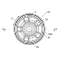
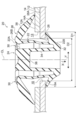
- FIG. 1 is a perspective view of a hole plug according to an embodiment of the present disclosure as viewed obliquely from above. It is a top view of the hole plug shown by FIG.
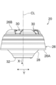
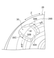
- FIG. 3 is a cross-sectional view taken along line 3-3 of the hole plug shown in FIG. 2; It is a side view of the hole plug shown by FIG. It is an enlarged view of the groove
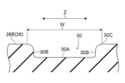
- FIG. 6 is a cross-sectional view taken along line 6-6 of the groove of the hole plug shown in FIG. 5; It is sectional drawing (sectional drawing corresponding to FIG. 3) of the hole plug which shows the state inserted in the 1st attachment hole of 2 panel members which piled up the hole plug shown in FIG. 1, and the 2nd attachment hole. It is sectional drawing (sectional drawing corresponding to FIG. 6) of the groove
- the hole plug 20 of the present embodiment is a member that closes the mounting hole formed in the plate-like portion of the mounting member.
- Arrows X shown in some of FIGS. 1 to 7 indicate the insertion direction of the hole plug 20 (hereinafter referred to as “plug insertion direction” as appropriate), and the arrow Y indicates the radial direction of the hole plug 20 (
- the “plug radial direction” is appropriately described, and the arrow Z indicates the circumferential direction of the hole plug 20 (hereinafter, appropriately described as “plug circumferential direction”).
- a symbol CL indicates a center line of the hole plug 20.
- the inner side in the plug radial direction refers to the side closer to the center line CL along the plug radial direction
- the outer side in the plug radial direction refers to the side farther from the center line CL along the plug radial direction.
- the hole plug 20 is to be attached to the attached member 12 and the attached member 14.
- the mounting member 12 has a plate-like portion 12A, and a through hole 13 is formed in the plate-like portion 12A.
- the through hole 13 has a diameter larger than that of a through hole 15 formed in a mounting member 14 described later. Specifically, the diameter D1 of the through hole 13 is larger than the diameter D2 of the through hole 15.
- the mounting member 12 is, for example, a panel member (a body panel or the like) of a vehicle.
- the mounting member 14 has a plate-like portion 14A, and a through hole 15 is formed in the plate-like portion 14A. Further, the mounting member 14 is mounted to the mounting member 12 in a state where the through hole 15 is aligned with the through hole 13 of the mounting member 12.
- the mounting member 14 is, for example, a bracket attached to a panel member of a vehicle. Further, the mounting member 14 of the present embodiment is an example of the mounting member in the present disclosure, and the through hole 15 is an example of the mounting hole of the mounting member in the present disclosure.
- the hole plug 20 includes an outer peripheral wall 22, a closing part 24, a flange 26, a claw 28 and a groove 30.
- the hole plug 20 of the present embodiment is an integrally molded product made of an elastically deformable resin.
- the outer peripheral wall part 22 is made cylindrical (this embodiment cylindrical shape), and it inserts in the through-hole 13 of the to-be-attached member 12, and the through-hole 15 of the to-be-attached member 14 It is supposed to be
- the cylindrical shape in the present embodiment includes those having a perfect circle and an elliptical cross-sectional shape.
- the toroidal ring includes a true circle and an ellipse.
- the closing portion 24 is bridged to the inside of the outer peripheral wall 22 and closes the inside of the outer peripheral wall 22. For this reason, in the engaged state in which the claws 28 of the hole plug 20 are engaged with the edge 15A of the through hole 15 of the mounting member 14 (hereinafter referred to as the "nail engaged state" as appropriate) The through hole 15 is closed by 24.
- the closed portion 24 has an annular projecting portion 32 projecting inward in the plug radial direction from the end 22B in the plug inserting direction of the outer peripheral wall portion 22 and an inner peripheral end of the projecting portion 32 opposite to the plug inserting direction
- a cylindrical inner peripheral wall portion 34 extending to the side and a face plate portion 36 bridged between the end portions of the inner peripheral wall portion 34 opposite to the plug insertion direction are provided.
- the flange portion 26 protrudes outward in the plug radial direction from the end 22A opposite to the plug insertion direction of the outer peripheral wall portion 22, and is annular (in this embodiment, annular) Is formed.
- the flange portion 26 of the present embodiment has a diameter D3 at the tip end portion 26A larger than the diameter D1 of the through hole 13 of the mounting member 12 in the unloaded state. For this reason, in the engaged state in which the claws 28 of the hole plug 20 are engaged with the edge 15A of the through hole 15 of the mounting member 14, the flange portion 26 and the periphery of the through hole 15 of the mounting member 14 and the mounting The periphery of the through hole 13 of the member 12 is covered (see FIG. 7).
- a raised portion 38 is formed on the surface of an intermediate portion between the distal end portion 26A and the proximal end portion 26B.
- the thickness of the raised portion 38 is thicker than the tip end 26A and the base end 26B of the flange 26.
- the claws 28 project outward from the end 22B of the outer peripheral wall 22 in the plug insertion direction toward the outer side in the plug radial direction and the opposite side to the plug insertion direction.
- the claws 28 are formed continuously along the outer periphery of the outer peripheral wall 22 and have an annular shape.
- the diameter D4 at the tip of the claw portion 28 is larger than the diameter D2 of the through hole 15 in the unloaded state.
- the claw portion 28 When the diameter-reduced claw portion 28 comes out of the through hole 15, the claw portion 28 is restored to the original state. Since the diameter D4 at the tip of the claw portion 28 is larger than the diameter D2 of the through hole 15, the force in the removal direction (the opposite direction to the insertion direction) is applied to the through hole 15 in the hole plug 20 When activated, the claws 28 engage (abut) the edge 15A of the through hole 15, and the movement in the removal direction is restricted (see FIG. 7).
- a plurality of grooves 30 are formed on the surface of the base end portion 26B of the flange portion 26 at intervals in the plug circumferential direction (the same direction as the circumferential direction of the flange portion 26). .
- the groove 30 extends from the outer peripheral wall 22 toward the flange 26 as shown in FIGS. 3 and 5. Specifically, the groove 30 is formed to straddle the end 22 B of the outer peripheral wall 22 and the base end 26 B of the flange 26.
- the groove 30 of the present embodiment is an example of the recess in the present disclosure.
- the bottom 30A of the groove 30 is flat.
- the portion of the hole plug 20 in which the groove 30 is formed has a reduced thickness.
- the groove width W of the groove 30 is larger at the opening 30C side than the bottom 30A.
- “the groove width W of the groove 30” is a length obtained by measuring the groove 30 along the plug circumferential direction.
- the opening width of the groove 30 is the largest at the base end portion 26 B of the flange portion 26.
- the “opening width of the groove 30” refers to the groove width at the opening 30C of the groove 30.
- five grooves 30 are formed on the surface of the base end portion 26B of the flange portion 26 at equal intervals in the circumferential direction of the plug.
- the groove width W is set such that the side wall portions 30B of the groove 30 do not abut each other even when the flange portion 26 is deformed to be parallel to the plug radial direction. .
- the outer peripheral wall portion 22 is inserted into the through hole 13 and the through hole 15 while pressing the face plate portion 36 of the closed portion 24.
- the claws 28 are restored and engaged with the edge 15 A of the through hole 15 as described above. This prevents the hole plug 20 from coming off the through hole 15.
- the outer peripheral wall portion 22 and the closing portion 24 close the through hole 15, and the flange portion 26 is the periphery of the through hole 15 of the mounting member 14 and the through hole 13 of the mounting member 12 Cover the periphery of the Therefore, the through hole 15 and the through hole 13 are blinded and stopped by the hole plug 20.
- the flange portion 26 since the plurality of grooves 30 are formed on the surface of the base end portion 26B of the flange portion 26, when the flange portion 26 abuts on the periphery of the through hole 13 at the time of insertion, The flange portion 26 is deformed starting from the groove 30. When the flange portion 26 is deformed, a force in the radial direction acts on the distal end portion 26A based on the insertion force of the hole plug 20, and a force in the radial direction acts on the proximal end portion 26B.
- the groove 30 is formed by forming the groove 30 on the surface of the proximal end 26B. Is a relief site for deformation due to external force, and the stress is reduced.
- the flange portion 26 is easily deformed starting from the groove 30, and the insertion force of the hole plug 20 into the through hole is reduced.
- the flange portion 26 is deformed starting from the groove 30 as compared with a configuration in which the bottom portion is sharp like a V-shaped cross section groove.
- the insertion force into the through hole is effectively reduced as compared with that in which a groove having a V-shaped cross section is formed on the surface of the base end 26B of the flange portion 26.
- the insertion force of the hole plug 20 into the through hole can be reduced, and therefore, the thickness of the flange portion 26 does not have to be reduced, and the occurrence of warpage of the flange portion 26 can be suppressed. .
- the groove 30 is extended from the outer peripheral wall portion 22 toward the flange portion 26, the groove 30 is added to the surface side of the base end portion 26B where an excessive stress is generated due to the deformation of the flange portion 26 Stress is also reduced in parts. Therefore, the insertion force of the hole plug 20 into the through hole is further reduced. Furthermore, in order to extend the groove 30 from the outer peripheral wall portion 22 toward the flange portion 26, the diameter of the base end portion 26B of the flange portion 26 is reduced. Specifically, as shown in FIG. 7, the proximal end 26B can be brought closer to the center line 26.
- the opening width of the groove 30 is the largest at the base end 26B of the flange portion 26, the groove 30 on the surface side of the base end 26B where excessive stress is generated by the deformation of the flange portion 26.
- the side wall portions 30B of the first and second side walls 30B are more difficult to contact with each other.
- the groove width W of the groove 30 is larger on the opening 30C side than the bottom 30A, for example, the groove width W of the groove 30 is the same on the bottom 30A and the opening 30C or on the opening 30C side than the bottom 30A.
- the side wall portions 30B of the groove 30 are less likely to abut each other when the flange portion 26 is deformed.
- the flange portion 26 can be deformed so as to be more parallel to the plug radial direction, and the mountable plate thickness tolerance It can be improved.
- the grooves 30 are formed in the flange portion 26 at equal intervals in the circumferential direction of the plug, when the flange portion 26 is deformed starting from the plurality of grooves 30, the flange portion 26 is made circumferentially It can be deformed (balanced) in a balanced manner. Furthermore, since five grooves 30 are formed in flange portion 26, that is, grooves 30 are formed at an angle of 72 degrees or less from center line CL, for example, an angle of four or less, ie, 90 degrees or more The flange portion 26 can be deformed (expanded) in a well-balanced manner in the circumferential direction of the plug as compared with the one formed by the above.
- the bottom 30A of the groove 30 is formed to be flat, but the present disclosure is not limited to this configuration.
- the bottom 40A may be formed in a curved surface like the groove 40 shown in FIG. Also in this case, the effect of reducing the insertion force of the hole plug into the through hole can be obtained as in the above-described embodiment.
- the bottom portion 40A of the groove 40 in a curved surface shape, it is possible to suppress concentration of stress on the bottom portion 40A when the flange portion 26 is deformed.
- the groove 30 extending from the outer peripheral wall 22 toward the flange 26 is formed on the surface of the base end 26B of the flange 26, but the present disclosure is not limited to this configuration.
- a circular or polygonal recess may be formed on the surface of the base end portion 26B of the flange portion 26.
- the opening width of the groove 30 is configured to be the largest at the base end 26B of the flange portion 26, but the present disclosure is not limited to this configuration.
- the opening width of the groove 30 may be the same in size from one end of the groove 30 to the other end.
- grooves 30 are formed in the flange portion 26 in the above embodiment, the present disclosure is not limited to this structure. For example, six or more may be sufficient.
- the claws 28 project from the end 22B side of the outer peripheral wall 22 (the end 22B side from the center of the outer peripheral wall 22 in the plug insertion direction), but the present disclosure is limited to this configuration I will not.
- the claws 28 may project from the end 22B of the outer peripheral wall 22.
- claw part 28 is formed in cyclic
- a plurality of claws 28 may be formed on the outer circumferential surface of the outer circumferential wall 22 at intervals in the circumferential direction of the plug.
- penetration hole 13 of mounting member 12 and penetration hole 15 of mounting member 14 are closed with hole plug 20
- this indication is not limited to this composition.
- the through-hole of one mounting member for example, panel material
- the through-hole of three or more mounting members may be closed.
- a cylindrical outer peripheral wall portion inserted into a mounting hole formed in the mounting member; A closed portion which is bridged inside the outer peripheral wall and closes the inside of the outer peripheral wall; An annular flange portion which projects from the end opposite to the insertion direction of the outer peripheral wall radially outward of the outer peripheral wall and covers the peripheral portion of the mounting hole; A claw that protrudes radially outward from an end side in the insertion direction of the outer peripheral wall and that engages with an edge of the mounting hole; A plurality of recesses formed on the surface of the base end portion of the flange portion at intervals in the circumferential direction of the flange portion, the bottom portion having a planar or curved surface shape; With a hole plug.
- the hole plug since a plurality of concave portions are formed on the surface of the base end portion of the flange portion, when the flange portion abuts on the peripheral portion of the mounting hole, the flange portion is deformed starting from these concave portions . In other words, the stress generated by the deformation of the flange portion is reduced by the plurality of recesses. For this reason, in the hole plug, for example, the insertion force into the mounting hole is reduced compared to the case where the recess is not formed on the surface of the base end portion of the flange portion.
- the flange portion is deformed starting from the recess as compared with the configuration in which the bottom is pointed like a V-shaped groove.
- the insertion force into the mounting hole is effectively reduced as compared with that in which the groove of the V-shaped cross section is formed on the surface of the base end portion of the flange portion.
- the recess is a groove extending from the outer peripheral wall toward the flange, stress is applied to the surface of the base end where excessive stress is generated due to deformation of the flange and also in the peripheral part Since the reduction is made, the insertion force into the mounting hole is further reduced.
- the opening width of the recess is the largest at the base end of the flange portion, the side wall portions of the recess are formed on the surface of the base end portion where excessive stress occurs due to deformation of the flange portion. Is more difficult to abut.
- the width of the recess is larger on the opening side than the bottom, for example, the width of the recess is the same on the bottom and the opening side or smaller than that on the opening At the time of deformation of the flange portion, it becomes difficult for the side wall portions of the recess to abut on each other.
- the flange portion is deformed in a well-balanced manner in the circumferential direction when the flange portion is deformed starting from a plurality of recessed portions. It is done (expanded).
- five or more concave portions are formed in the flange portion, that is, since the concave portions are formed at an angle of 72 degrees or less from the center of the outer peripheral wall portion, for example, four or less.
- the flange portion can be deformed (expanded) in a circumferential direction in a balanced manner as compared with the one formed at an angle of 90 degrees or more.
Landscapes
- Engineering & Computer Science (AREA)
- General Engineering & Computer Science (AREA)
- Mechanical Engineering (AREA)
- Chemical & Material Sciences (AREA)
- Combustion & Propulsion (AREA)
- Transportation (AREA)
- Pressure Vessels And Lids Thereof (AREA)
- Gasket Seals (AREA)
Abstract
ホールプラグは、被取付部材に形成された取付孔へ挿入される筒状の外周壁部と、外周壁部の内側に架け渡されて、外周壁部内を塞ぐ閉塞部と、外周壁部の挿入方向と反対側の端部から外周壁部の径方向外側へ張り出し、取付孔の周辺部を覆う環状のフランジ部と、外周壁部の挿入方向の端部側から前記径方向外側へ突出し、取付孔の縁部に係合する爪部と、フランジ部の基端部表面にフランジ部の周方向に間隔をあけて形成され、底部が平面状又は湾曲面状とされた複数の凹部と、を有する。
Description
本開示は、ホールプラグに関する。
特許第3881814号公報には、被取付部材(フロア板)に形成された取付孔(孔)に取り付けられるホールプラグ(グロメット)が開示されている。このホールプラグは、取付孔に挿入される筒状の外周壁部と、外周壁部内を塞ぐ閉塞部と、外周壁部の挿入方向と反対側の端部から径方向外側へ張り出す環状のフランジ部(非挿入部)とを備えている。また、フランジ部の表面には、先端部から基端部に向かって幅が広がるV字断面の溝(切欠開溝)が該フランジ部の周方向に間隔をあけて複数形成されている。
ところで、特許第3881814号公報に開示されたホールプラグを被取付部材に取り付ける場合、ホールプラグを取付孔に押し込むと、溝を起点としてフランジ部が変形するため、挿入力を低減することができる。しかし、フランジ部の変形時に溝壁同士が当接すると、溝を起点にした変形が制限され、ホールプラグを取付孔に押し込むときの挿入力低減効果が十分に得られない虞がある。
本開示は上記事実を考慮し、被取付部材に形成された取付孔への挿入力を低減可能なホールプラグを提供することを目的とする。
本開示の一態様のホールプラグは、被取付部材に形成された取付孔へ挿入される筒状の外周壁部と、前記外周壁部の内側に架け渡されて、前記外周壁部内を塞ぐ閉塞部と、前記外周壁部の挿入方向と反対側の端部から前記外周壁部の径方向外側へ張り出し、前記取付孔の周辺部を覆う環状のフランジ部と、前記外周壁部の前記挿入方向の端部側から前記径方向外側へ突出し、前記取付孔の縁部に係合する爪部と、前記フランジ部の基端部表面に前記フランジ部の周方向に間隔をあけて形成され、底部が平面状又は湾曲面状とされた複数の凹部と、を有する。
本開示は、被取付部材に形成された取付孔への挿入力を低減可能なホールプラグを提供することができる。
次に、本開示の一実施形態に係るホールプラグ20を図1~図7を用いて説明する。
本実施形態のホールプラグ20は、被取付部材が有する板状部に形成された取付孔を塞ぐ部材である。なお、図1~図7の一部の図面に示す矢印Xはホールプラグ20の挿入方向(以下、適宜「プラグ挿入方向」と記載する。)を示し、矢印Yはホールプラグ20の径方向(以下、適宜「プラグ径方向」と記載する。)を示し、矢印Zはホールプラグ20の周方向(以下、適宜「プラグ周方向」と記載する。)を示している。また、符号CLは、ホールプラグ20の中心線を示している。なお、プラグ径方向内側とは、プラグ径方向に沿って中心線CLに近い側を指しており、プラグ径方向外側とは、プラグ径方向に沿って中心線CLから遠い側を指している。
本実施形態のホールプラグ20は、被取付部材が有する板状部に形成された取付孔を塞ぐ部材である。なお、図1~図7の一部の図面に示す矢印Xはホールプラグ20の挿入方向(以下、適宜「プラグ挿入方向」と記載する。)を示し、矢印Yはホールプラグ20の径方向(以下、適宜「プラグ径方向」と記載する。)を示し、矢印Zはホールプラグ20の周方向(以下、適宜「プラグ周方向」と記載する。)を示している。また、符号CLは、ホールプラグ20の中心線を示している。なお、プラグ径方向内側とは、プラグ径方向に沿って中心線CLに近い側を指しており、プラグ径方向外側とは、プラグ径方向に沿って中心線CLから遠い側を指している。
図7に示されるように、ホールプラグ20は、被取付部材12及び被取付部材14に取り付けられるようになっている。
被取付部材12は、板状部12Aを有しており、この板状部12Aに貫通孔13が形成されている。この貫通孔13は、後述する被取付部材14に形成された貫通孔15よりも大径とされている。具体的には、貫通孔13の径D1は、貫通孔15の径D2よりも大きくされている。なお、被取付部材12は、例えば、車両のパネル部材(ボディパネルなど)である。
被取付部材14は、板状部14Aを有しており、この板状部14Aに貫通孔15が形成されている。また、被取付部材14は、被取付部材12の貫通孔13に貫通孔15を合わせた状態で、被取付部材12に取り付けられている。なお、被取付部材14は、例えば、車両のパネル部材に取り付けられるブラケットなどである。
また、本実施形態の被取付部材14は、本開示における被取付部材の一例であり、貫通孔15は、本開示における被取付部材の取付孔の一例である。
また、本実施形態の被取付部材14は、本開示における被取付部材の一例であり、貫通孔15は、本開示における被取付部材の取付孔の一例である。
本実施形態では、ホールプラグ20の後述する爪部28が被取付部材14の貫通孔15の縁部15Aに係合した状態(図7図示状態)においては、被取付部材12の貫通孔13の周辺部までが後述するフランジ部26によって覆われている。
図1~図3に示されるように、ホールプラグ20は、外周壁部22と、閉塞部24と、フランジ部26と、爪部28と、溝30と、を備えている。なお、本実施形態のホールプラグ20は、弾性変形可能な樹脂で構成された一体成型品である。
図3及び図7に示されるように、外周壁部22は、筒状(本実施形態では、円筒状)とされ、被取付部材12の貫通孔13及び被取付部材14の貫通孔15に挿入されるようになっている。なお、本実施形態でいう円筒状には、断面形状が真円及び楕円のものが含まれる。また、本実施形態でいう円環状には、真円及び楕円のものが含まれる。
図2及び図3に示されるように、閉塞部24は、外周壁部22の内側に架け渡されており、外周壁部22の内側を閉塞している。このため、ホールプラグ20の爪部28が被取付部材14の貫通孔15の縁部15Aに係合した係合状態(以下、適宜「爪部係合状態」と記載する。)では、閉塞部24によって貫通孔15が塞がれる。この閉塞部24は、外周壁部22のプラグ挿入方向の端部22Bからプラグ径方向内側へ張り出す円環状の張出部32と、張出部32の内周端部からプラグ挿入方向と反対側へ延びる円筒状の内周壁部34と、内周壁部34のプラグ挿入方向と反対側の端部間に架け渡された面板部36とを備えている。
図1及び図3に示されるように、フランジ部26は、外周壁部22のプラグ挿入方向と反対側の端部22Aからプラグ径方向外側へ張り出しており、環状(本実施形態では、円環状)に形成されている。本実施形態のフランジ部26は、無負荷状態において、先端部26Aにおける径D3が被取付部材12の貫通孔13の径D1よりも大径とされている。このため、ホールプラグ20の爪部28が被取付部材14の貫通孔15の縁部15Aに係合した係合状態では、フランジ部26によって被取付部材14の貫通孔15の周辺部及び被取付部材12の貫通孔13の周辺部が覆われる(図7参照)。
また、本実施形態のフランジ部26は、先端部26Aと基端部26Bとの間の中間部分表面に隆起部38が形成されている。この隆起部38における厚みは、フランジ部26の先端部26A及び基端部26Bよりも肉厚とされている。
図3に示されるように、爪部28は、外周壁部22のプラグ挿入方向の端部22B側からプラグ径方向外側で且つプラグ挿入方向と反対側へ向けて突出している。また、爪部28は、外周壁部22の外周に沿って連続して形成されており、円環状とされている。この爪部28の先端における径D4は、無負荷状態で貫通孔15の径D2よりも大径とされている。ここで、ホールプラグ20(外周壁部22)の貫通孔15への挿入時には、爪部28の外周面が貫通孔15の内周面に当接し、爪部28が縮径方向に変形する。縮径状態の爪部28が貫通孔15から抜け出ると、爪部28は元の状態に復元する。そして、爪部28の先端における径D4が貫通孔15の径D2よりも大径とされていることから、ホールプラグ20に貫通孔15に対して抜去方向(挿入方向と反対方向)の力が作用すると、爪部28が貫通孔15の縁部15Aに係合(当接)して、抜去方向の移動が制限される(図7参照)。
図1及び図2に示されるように、溝30は、フランジ部26の基端部26Bの表面にプラグ周方向(フランジ部26の周方向と同じ方向)に間隔をあけて複数形成されている。この溝30は、図3及び図5に示されるように、外周壁部22からフランジ部26に向けて延びている。具体的には、溝30は、外周壁部22の端部22Bとフランジ部26の基端部26Bを跨ぐように形成されている。なお、本実施形態の溝30は、本開示における凹部の一例である。
図4~図6に示されるように、溝30の底部30Aは、平面状とされている。なお、ホールプラグ20の溝30が形成された部分は、厚みが薄くなっている。
図6に示されるように、溝30の溝幅Wは、底部30Aよりも開口30C側で大きくなっている。なお、ここでいう「溝30の溝幅W」とは、溝30をプラグ周方向に沿って計測した長さである。
また、溝30の開口幅は、フランジ部26の基端部26Bで最も大きくなっている。なお、ここでいう「溝30の開口幅」とは、溝30の開口30Cにおける溝幅を指している。
また、図2に示されるように、本実施形態では、フランジ部26の基端部26Bの表面に溝30を5つプラグ周方向に等間隔に形成している。
そして、本実施形態では、フランジ部26をプラグ径方向に対して平行となるまで変形させた状態でも、溝30の側壁部30B同士が非当接となるように溝幅Wが設定されている。
次に、本実施形態のホールプラグ20の作用効果について説明する。
ホールプラグ20では、閉塞部24の面板部36を押しながら、外周壁部22を貫通孔13及び貫通孔15に挿入する。外周壁部22が貫通孔15に所定量挿入されると、上記のように、爪部28が復元して貫通孔15の縁部15Aに係合する。これにより、ホールプラグ20の貫通孔15からの抜けが防止される。また、爪部28の係合状態では、外周壁部22と閉塞部24が貫通孔15を塞ぐと共にフランジ部26が被取付部材14の貫通孔15の周辺部及び被取付部材12の貫通孔13の周辺部を覆う。このため、ホールプラグ20によって貫通孔15及び貫通孔13が目隠し及び止水される。
ホールプラグ20では、閉塞部24の面板部36を押しながら、外周壁部22を貫通孔13及び貫通孔15に挿入する。外周壁部22が貫通孔15に所定量挿入されると、上記のように、爪部28が復元して貫通孔15の縁部15Aに係合する。これにより、ホールプラグ20の貫通孔15からの抜けが防止される。また、爪部28の係合状態では、外周壁部22と閉塞部24が貫通孔15を塞ぐと共にフランジ部26が被取付部材14の貫通孔15の周辺部及び被取付部材12の貫通孔13の周辺部を覆う。このため、ホールプラグ20によって貫通孔15及び貫通孔13が目隠し及び止水される。
ここで、ホールプラグ20では、フランジ部26の基端部26Bの表面に複数の溝30を形成していることから、挿入時にフランジ部26が貫通孔13の周辺部に当接すると、これらの溝30を起点としてフランジ部26が変形する。このフランジ部26の変形時には、ホールプラグ20の挿入力を基にして、先端部26Aに拡径方向の力が作用し、基端部26Bに縮径方向の力が作用する。特に、フランジ部26の基端部26Bの表面には、大きな外力が作用するため、この外力に抵抗する応力も大きくなるが、基端部26Bの表面に溝30を形成することにより、溝30が外力による変形の逃げ場となり、応力が低減される。このように、基端部26Bの表面に溝30を形成することで、溝30を起点としてフランジ部26が変形しやすくなり、ホールプラグ20の貫通孔への挿入力が低減される。
また、ホールプラグ20では、溝30の底部30Aを平面状としていることから、例えば、V字断面の溝のように底部が尖っている構成と比べて、溝30を起点としてフランジ部26が変形する際に、溝30の側壁部30B同士が当接し難くなる。このため、ホールプラグ20は、例えば、V字断面の溝がフランジ部26の基端部26Bの表面に形成されるものと比べて、貫通孔への挿入力が効果的に低減される。また、フランジ部26に溝30を形成することで、ホールプラグ20の貫通孔への挿入力を低減できるため、フランジ部26の厚みを薄くする必要がなく、フランジ部26の反り発生を抑制できる。
また、ホールプラグ20では、溝30の底部30Aを平面状としていることから、例えば、V字断面の溝のように底部が尖っている構成と比べて、溝30を起点としてフランジ部26が変形する際に、溝30の側壁部30B同士が当接し難くなる。このため、ホールプラグ20は、例えば、V字断面の溝がフランジ部26の基端部26Bの表面に形成されるものと比べて、貫通孔への挿入力が効果的に低減される。また、フランジ部26に溝30を形成することで、ホールプラグ20の貫通孔への挿入力を低減できるため、フランジ部26の厚みを薄くする必要がなく、フランジ部26の反り発生を抑制できる。
また、ホールプラグ20では、溝30を外周壁部22からフランジ部26に向けて延ばしていることから、フランジ部26の変形によって過大な応力が生じる基端部26Bの表面側に加え、その周辺部分においても応力が低減される。このため、ホールプラグ20の貫通孔への挿入力がさらに低減される。さらに、溝30を外周壁部22からフランジ部26に向けて延ばすため、フランジ部26の基端部26Bを縮径させられる。具体的には、図7に示されるように、基端部26Bを中心線26に近づけられるようになる。
ホールプラグ20では、溝30の開口幅をフランジ部26の基端部26Bで最も大きくしていることから、フランジ部26の変形によって過大な応力が生じる基端部26Bの表面側において、溝30の側壁部30B同士がさらに当接し難くなる。また、溝30の溝幅Wを底部30Aよりも開口30C側で大きくしていることから、例えば、溝30の溝幅Wが底部30Aと開口30C側で同じ又は底部30Aよりも開口30C側で小さいものと比べて、フランジ部26の変形時に溝30の側壁部30B同士が当接し難くなる。このように、溝30の側壁部30B同士が当接し難くなることで、プラグ径方向に対してフランジ部26をより平行に近づくまで変形させることが可能となり、取付可能な板厚の許容値を向上させることができる。
また、ホールプラグ20では、溝30をフランジ部26にプラグ周方向に等間隔で形成していることから、複数の溝30を起点としたフランジ部26の変形時に、フランジ部26を周方向にバランスよく変形させられる(拡げられる)。さらに、溝30をフランジ部26に5つ形成している、すなわち、溝30を中心線CLから72度以下の角度で形成しているので、例えば、4つ以下、すなわち、90度以上の角度で形成するものと比べて、フランジ部26をプラグ周方向にバランスよく変形させられる(拡げられる)。
(その他の実施形態)
前述の実施形態では、図6に示されるように、溝30の底部30Aを平面状に形成しているが、本開示はこの構成に限定されない。例えば、図8に示される溝40のように底部40Aを湾曲面状に形成してもよい。この場合においても、前述の実施形態と同様に、ホールプラグの貫通孔への挿入力低減効果が得られる。また、溝40の底部40Aを湾曲面状に形成することで、フランジ部26の変形時に底部40Aに応力が集中するのを抑制することができる。
前述の実施形態では、図6に示されるように、溝30の底部30Aを平面状に形成しているが、本開示はこの構成に限定されない。例えば、図8に示される溝40のように底部40Aを湾曲面状に形成してもよい。この場合においても、前述の実施形態と同様に、ホールプラグの貫通孔への挿入力低減効果が得られる。また、溝40の底部40Aを湾曲面状に形成することで、フランジ部26の変形時に底部40Aに応力が集中するのを抑制することができる。
前述の実施形態では、フランジ部26の基端部26Bの表面に外周壁部22からフランジ部26に向けて延びる溝30を形成する構成としているが、本開示はこの構成に限定されない。例えば、フランジ部26の基端部26Bの表面に円形や多角形の凹部を形成する構成としてもよい。
前述の実施形態では、溝30の開口幅をフランジ部26の基端部26Bで最も大きくする構成としているが、本開示はこの構成に限定されない。例えば、溝30の開口幅を溝30の一端から他端まですべて同じ大きさとする構成としてもよい。
前述の実施形態では、溝30をフランジ部26に5つ形成する構成としているが、本開示はこの構成に限定されない。例えば、6つ以上であってもよい。
前述の実施形態では、外周壁部22の端部22B側(外周壁部22のプラグ挿入方向の中央よりも端部22B側)から爪部28が突出しているが、本開示はこの構成に限定されない。例えば、外周壁部22の端部22Bから爪部28が突出していてもよい。
また、前述の実施形態では、爪部28を円環状に形成しているが、本開示はこの構成に限定されない。爪部28を外周壁部22の外周面にプラグ周方向に間隔をあけて複数形成する構成としてもよい。
また、前述の実施形態では、爪部28を円環状に形成しているが、本開示はこの構成に限定されない。爪部28を外周壁部22の外周面にプラグ周方向に間隔をあけて複数形成する構成としてもよい。
前述の実施形態では、被取付部材12の貫通孔13と被取付部材14の貫通孔15をホールプラグ20で塞いでいるが、本開示はこの構成に限定されない。例えば、ホールプラグ20で1つの被取付部材(例えば、パネル材)の貫通孔を塞ぐ構成であってもよいし、3つ以上の被取付部材の各貫通孔を塞ぐ構成であってもよい。
以上、本開示の一実施形態について説明したが、本開示は、上記に限定されるものでなく、その主旨を逸脱しない範囲内において上記以外にも種々変形して実施することが可能であることは勿論である。
以上の実施形態に関し、更に以下の付記を開示する。
(付記1)
被取付部材に形成された取付孔へ挿入される筒状の外周壁部と、
前記外周壁部の内側に架け渡されて、前記外周壁部内を塞ぐ閉塞部と、
前記外周壁部の挿入方向と反対側の端部から前記外周壁部の径方向外側へ張り出し、前記取付孔の周辺部を覆う環状のフランジ部と、
前記外周壁部の前記挿入方向の端部側から前記径方向外側へ突出し、前記取付孔の縁部に係合する爪部と、
前記フランジ部の基端部表面に前記フランジ部の周方向に間隔をあけて形成され、底部が平面状又は湾曲面状とされた複数の凹部と、
を有するホールプラグ。
被取付部材に形成された取付孔へ挿入される筒状の外周壁部と、
前記外周壁部の内側に架け渡されて、前記外周壁部内を塞ぐ閉塞部と、
前記外周壁部の挿入方向と反対側の端部から前記外周壁部の径方向外側へ張り出し、前記取付孔の周辺部を覆う環状のフランジ部と、
前記外周壁部の前記挿入方向の端部側から前記径方向外側へ突出し、前記取付孔の縁部に係合する爪部と、
前記フランジ部の基端部表面に前記フランジ部の周方向に間隔をあけて形成され、底部が平面状又は湾曲面状とされた複数の凹部と、
を有するホールプラグ。
付記1のホールプラグを被取付部材の取付孔へ取り付ける場合、閉塞部を押しながら外周壁部を取付孔内へ挿入する。外周壁部が取付孔内へ挿入されると、爪部が取付孔の縁部に係合し、ホールプラグの取付孔からの抜けが防止される。また、爪部の係合状態では、外周壁部と閉塞部が取付孔を塞ぐと共にフランジ部が取付孔の周辺部を覆うため、取付孔がホールプラグによって目隠し及び止水される。
ここで、上記ホールプラグでは、フランジ部の基端部表面に複数の凹部を形成していることから、フランジ部が取付孔周辺部に当接すると、これらの凹部を起点としてフランジ部が変形する。言い換えると、フランジ部の変形によって生じる応力が複数の凹部によって低減される。このため、上記ホールプラグは、例えば、フランジ部の基端部表面に凹部が形成されないものと比べて、取付孔への挿入力が低減される。
特に、上記ホールプラグでは、凹部の底部を平面状又は湾曲面状としていることから、例えば、V字断面の溝のように底部が尖っている構成と比べて、凹部を起点としてフランジ部が変形する際に、凹部の側壁部同士が当接し難くなる。このため、上記ホールプラグは、例えば、V字断面の溝がフランジ部の基端部表面に形成されるものと比べて、取付孔への挿入力が効果的に低減される。
ここで、上記ホールプラグでは、フランジ部の基端部表面に複数の凹部を形成していることから、フランジ部が取付孔周辺部に当接すると、これらの凹部を起点としてフランジ部が変形する。言い換えると、フランジ部の変形によって生じる応力が複数の凹部によって低減される。このため、上記ホールプラグは、例えば、フランジ部の基端部表面に凹部が形成されないものと比べて、取付孔への挿入力が低減される。
特に、上記ホールプラグでは、凹部の底部を平面状又は湾曲面状としていることから、例えば、V字断面の溝のように底部が尖っている構成と比べて、凹部を起点としてフランジ部が変形する際に、凹部の側壁部同士が当接し難くなる。このため、上記ホールプラグは、例えば、V字断面の溝がフランジ部の基端部表面に形成されるものと比べて、取付孔への挿入力が効果的に低減される。
(付記2)
前記凹部は、前記外周壁部から前記フランジ部に向けて延びる溝である、付記1に記載のホールプラグ。
前記凹部は、前記外周壁部から前記フランジ部に向けて延びる溝である、付記1に記載のホールプラグ。
付記2のホールプラグでは、凹部を外周壁部からフランジ部に向けて延びる溝としていることから、フランジ部の変形によって過大な応力が生じる基端部表面側に加え、その周辺部分においても応力が低減されるため、取付孔への挿入力がさらに低減される。
(付記3)
前記凹部の開口幅は、前記フランジ部の基端部で最も大きい、付記2に記載のホールプラグ。
前記凹部の開口幅は、前記フランジ部の基端部で最も大きい、付記2に記載のホールプラグ。
付記3のホールプラグでは、凹部の開口幅を、フランジ部の基端部で最も大きくしていることから、フランジ部の変形によって過大な応力が生じる基端部表面側において、凹部の側壁部同士がさらに当接し難くなる。
(付記4)
前記凹部の幅は、前記底部よりも前記凹部の開口側で大きくなっている、付記1~3のいずれか1項に記載のホールプラグ。
前記凹部の幅は、前記底部よりも前記凹部の開口側で大きくなっている、付記1~3のいずれか1項に記載のホールプラグ。
付記4のホールプラグでは、凹部の幅を、底部よりも開口側で大きくしていることから、例えば、凹部の幅が底部と開口側で同じ又は底部よりも開口側で小さいものと比べて、フランジ部の変形時に凹部の側壁部同士が当接し難くなる。
(付記5)
前記凹部は、前記フランジ部に前記周方向に等間隔で形成されている、付記1~4のいずれか1項に記載のホールプラグ。
前記凹部は、前記フランジ部に前記周方向に等間隔で形成されている、付記1~4のいずれか1項に記載のホールプラグ。
付記5のホールプラグでは、凹部をフランジ部にフランジ部の周方向に等間隔で形成していることから、複数の凹部を起点としたフランジ部の変形時に、フランジ部を周方向にバランスよく変形させられる(拡げられる)。
(付記6)
前記凹部は、前記フランジ部に5つ以上形成されている、付記5に記載のホールプラグ。
前記凹部は、前記フランジ部に5つ以上形成されている、付記5に記載のホールプラグ。
付記6のホールプラグでは、凹部をフランジ部に5つ以上形成している、すなわち、凹部を外周壁部の中心から72度以下の角度で形成しているので、例えば、4つ以下、すなわち、90度以上の角度で形成するものと比べて、フランジ部を周方向にバランスよく変形させられる(拡げられる)。
なお、2017年12月27日に出願された日本国特許出願2017-25223号の開示は、その全体が参照により本明細書に取り込まれる。
本明細書に記載された全ての文献、特許出願、および技術規格は、個々の文献、特許出願、および技術規格が参照により取り込まれることが具体的かつ個々に記された場合と同程度に、本明細書中に参照により取り込まれる。
本明細書に記載された全ての文献、特許出願、および技術規格は、個々の文献、特許出願、および技術規格が参照により取り込まれることが具体的かつ個々に記された場合と同程度に、本明細書中に参照により取り込まれる。
Claims (6)
- 被取付部材に形成された取付孔へ挿入される筒状の外周壁部と、
前記外周壁部の内側に架け渡されて、前記外周壁部内を塞ぐ閉塞部と、
前記外周壁部の挿入方向と反対側の端部から前記外周壁部の径方向外側へ張り出し、前記取付孔の周辺部を覆う環状のフランジ部と、
前記外周壁部の前記挿入方向の端部側から前記径方向外側へ突出し、前記取付孔の縁部に係合する爪部と、
前記フランジ部の基端部表面に前記フランジ部の周方向に間隔をあけて形成され、底部が平面状又は湾曲面状とされた複数の凹部と、
を有するホールプラグ。 - 前記凹部は、前記外周壁部から前記フランジ部に向けて延びる溝である、請求項1に記載のホールプラグ。
- 前記凹部の開口幅は、前記フランジ部の基端部で最も大きい、請求項2に記載のホールプラグ。
- 前記凹部の幅は、前記底部よりも前記凹部の開口側で大きくなっている、請求項1~3のいずれか1項に記載のホールプラグ。
- 前記凹部は、前記フランジ部に前記周方向に等間隔で形成されている、請求項1~4のいずれか1項に記載のホールプラグ。
- 前記凹部は、前記フランジ部に5つ以上形成されている、請求項5に記載のホールプラグ。
Priority Applications (2)
| Application Number | Priority Date | Filing Date | Title |
|---|---|---|---|
| CN201880083204.2A CN111512076B (zh) | 2017-12-27 | 2018-10-29 | 孔塞 |
| US16/957,789 US11493130B2 (en) | 2017-12-27 | 2018-10-29 | Hole plug |
Applications Claiming Priority (2)
| Application Number | Priority Date | Filing Date | Title |
|---|---|---|---|
| JP2017252223A JP6783748B2 (ja) | 2017-12-27 | 2017-12-27 | ホールプラグ |
| JP2017-252223 | 2017-12-27 |
Publications (1)
| Publication Number | Publication Date |
|---|---|
| WO2019130793A1 true WO2019130793A1 (ja) | 2019-07-04 |
Family
ID=67067030
Family Applications (1)
| Application Number | Title | Priority Date | Filing Date |
|---|---|---|---|
| PCT/JP2018/040191 Ceased WO2019130793A1 (ja) | 2017-12-27 | 2018-10-29 | ホールプラグ |
Country Status (4)
| Country | Link |
|---|---|
| US (1) | US11493130B2 (ja) |
| JP (1) | JP6783748B2 (ja) |
| CN (1) | CN111512076B (ja) |
| WO (1) | WO2019130793A1 (ja) |
Cited By (1)
| Publication number | Priority date | Publication date | Assignee | Title |
|---|---|---|---|---|
| US11493130B2 (en) | 2017-12-27 | 2022-11-08 | Nifco Inc. | Hole plug |
Families Citing this family (2)
| Publication number | Priority date | Publication date | Assignee | Title |
|---|---|---|---|---|
| US20220381343A1 (en) * | 2021-05-31 | 2022-12-01 | Illinois Tool Works Inc. | Sealing Plug |
| US20230349589A1 (en) * | 2022-04-29 | 2023-11-02 | Carrier Corporation | Hole plug for hvac component |
Citations (3)
| Publication number | Priority date | Publication date | Assignee | Title |
|---|---|---|---|---|
| JP2001124246A (ja) * | 1999-10-27 | 2001-05-11 | Kinugawa Rubber Ind Co Ltd | グロメット |
| JP2011158049A (ja) * | 2010-02-02 | 2011-08-18 | Piolax Inc | 留め具 |
| JP2014114850A (ja) * | 2012-12-07 | 2014-06-26 | Nifco Inc | ホールプラグ |
Family Cites Families (17)
| Publication number | Priority date | Publication date | Assignee | Title |
|---|---|---|---|---|
| FR2805503B1 (fr) * | 2000-02-28 | 2002-05-31 | Itw De France | Obturateur pour une ouverture realisee dans une tole |
| US7048486B2 (en) * | 2002-07-10 | 2006-05-23 | Newfrey Llc | Insert part for a wall opening, in particular on a vehicle body |
| JP4740124B2 (ja) * | 2004-05-24 | 2011-08-03 | 大和化成工業株式会社 | ホールプラグ |
| JP4896679B2 (ja) * | 2006-11-24 | 2012-03-14 | 株式会社パイオラックス | ホールプラグ |
| JP2011064296A (ja) * | 2009-09-18 | 2011-03-31 | Nifco Inc | ホールプラグ |
| JP5498890B2 (ja) * | 2009-11-12 | 2014-05-21 | 株式会社ニフコ | 自動車用の閉塞栓 |
| JP2012241843A (ja) * | 2011-05-23 | 2012-12-10 | Nifco Inc | ホールプラグ |
| ES2415758B1 (es) * | 2011-06-20 | 2014-09-09 | Illinois Tool Works, Inc. | Tapón obturador de orificios |
| JP5921353B2 (ja) * | 2011-11-16 | 2016-05-24 | 株式会社ニフコ | ホールプラグ |
| JP6088231B2 (ja) * | 2012-12-07 | 2017-03-01 | 株式会社ニフコ | ホールプラグ |
| JP5859467B2 (ja) * | 2013-01-09 | 2016-02-10 | 株式会社ニフコ | ホールプラグ |
| JP6122336B2 (ja) * | 2013-04-22 | 2017-04-26 | 大和化成工業株式会社 | ホールプラグ |
| JP6214335B2 (ja) * | 2013-10-24 | 2017-10-18 | 株式会社ニフコ | ホールプラグ |
| DE102015102169B4 (de) * | 2015-02-16 | 2016-08-25 | Trw Automotive Electronics & Components Gmbh | Verschlussstopfen |
| FR3032947B1 (fr) * | 2015-02-24 | 2020-02-21 | Itw Fastener Products Gmbh | Bouchons d'etancheite , assemblage et methode pour etancheifier une ouverture |
| CN204528016U (zh) * | 2015-04-04 | 2015-08-05 | 蒋祥初 | 气囊密封塞 |
| JP6783748B2 (ja) | 2017-12-27 | 2020-11-11 | トヨタ車体株式会社 | ホールプラグ |
-
2017
- 2017-12-27 JP JP2017252223A patent/JP6783748B2/ja active Active
-
2018
- 2018-10-29 CN CN201880083204.2A patent/CN111512076B/zh active Active
- 2018-10-29 WO PCT/JP2018/040191 patent/WO2019130793A1/ja not_active Ceased
- 2018-10-29 US US16/957,789 patent/US11493130B2/en active Active
Patent Citations (3)
| Publication number | Priority date | Publication date | Assignee | Title |
|---|---|---|---|---|
| JP2001124246A (ja) * | 1999-10-27 | 2001-05-11 | Kinugawa Rubber Ind Co Ltd | グロメット |
| JP2011158049A (ja) * | 2010-02-02 | 2011-08-18 | Piolax Inc | 留め具 |
| JP2014114850A (ja) * | 2012-12-07 | 2014-06-26 | Nifco Inc | ホールプラグ |
Cited By (1)
| Publication number | Priority date | Publication date | Assignee | Title |
|---|---|---|---|---|
| US11493130B2 (en) | 2017-12-27 | 2022-11-08 | Nifco Inc. | Hole plug |
Also Published As
| Publication number | Publication date |
|---|---|
| US11493130B2 (en) | 2022-11-08 |
| US20210372523A1 (en) | 2021-12-02 |
| JP6783748B2 (ja) | 2020-11-11 |
| CN111512076A (zh) | 2020-08-07 |
| JP2019116953A (ja) | 2019-07-18 |
| CN111512076B (zh) | 2022-05-06 |
Similar Documents
| Publication | Publication Date | Title |
|---|---|---|
| JP5880457B2 (ja) | グロメット | |
| WO2019130793A1 (ja) | ホールプラグ | |
| JP2014211224A (ja) | ホールプラグ | |
| WO2013073481A1 (ja) | ホールプラグ | |
| JP2015198528A (ja) | グロメット | |
| WO2018143257A1 (ja) | ホールプラグ | |
| US20190092397A1 (en) | Hole plug | |
| WO2014088043A1 (ja) | ホールプラグ | |
| WO2019130792A1 (ja) | ホールプラグの取付構造 | |
| JP6571367B2 (ja) | ホールプラグ | |
| JP2019116953A5 (ja) | ||
| JP2019075234A (ja) | グロメット | |
| JP2012007695A (ja) | 栓 | |
| WO2012157614A1 (ja) | ホールプラグ | |
| JP2005188623A (ja) | クリップ | |
| JP7211882B2 (ja) | 取付構造 | |
| JP5911790B2 (ja) | ホールプラグ | |
| JP6393150B2 (ja) | 防音カバー | |
| JP2019075233A (ja) | グロメット | |
| JP7191483B2 (ja) | 留め具 | |
| JP2013217448A (ja) | ホールプラグ | |
| JP2017007463A (ja) | グロメット及びグロメット付ワイヤハーネス | |
| JP2022175754A (ja) | ホールプラグ | |
| JP6131905B2 (ja) | グロメット | |
| JP2005299747A (ja) | ホールプラグ |
Legal Events
| Date | Code | Title | Description |
|---|---|---|---|
| 121 | Ep: the epo has been informed by wipo that ep was designated in this application |
Ref document number: 18897269 Country of ref document: EP Kind code of ref document: A1 |
|
| DPE1 | Request for preliminary examination filed after expiration of 19th month from priority date (pct application filed from 20040101) | ||
| NENP | Non-entry into the national phase |
Ref country code: DE |
|
| 122 | Ep: pct application non-entry in european phase |
Ref document number: 18897269 Country of ref document: EP Kind code of ref document: A1 |