WO2019130456A1 - 空気調和機 - Google Patents
空気調和機 Download PDFInfo
- Publication number
- WO2019130456A1 WO2019130456A1 PCT/JP2017/046819 JP2017046819W WO2019130456A1 WO 2019130456 A1 WO2019130456 A1 WO 2019130456A1 JP 2017046819 W JP2017046819 W JP 2017046819W WO 2019130456 A1 WO2019130456 A1 WO 2019130456A1
- Authority
- WO
- WIPO (PCT)
- Prior art keywords
- heat exchanger
- plate
- partition plate
- outdoor
- side plate
- Prior art date
- Legal status (The legal status is an assumption and is not a legal conclusion. Google has not performed a legal analysis and makes no representation as to the accuracy of the status listed.)
- Ceased
Links
Images








Classifications
-
- F—MECHANICAL ENGINEERING; LIGHTING; HEATING; WEAPONS; BLASTING
- F24—HEATING; RANGES; VENTILATING
- F24F—AIR-CONDITIONING; AIR-HUMIDIFICATION; VENTILATION; USE OF AIR CURRENTS FOR SCREENING
- F24F1/00—Room units for air-conditioning, e.g. separate or self-contained units or units receiving primary air from a central station
- F24F1/06—Separate outdoor units, e.g. outdoor unit to be linked to a separate room comprising a compressor and a heat exchanger
-
- F—MECHANICAL ENGINEERING; LIGHTING; HEATING; WEAPONS; BLASTING
- F24—HEATING; RANGES; VENTILATING
- F24F—AIR-CONDITIONING; AIR-HUMIDIFICATION; VENTILATION; USE OF AIR CURRENTS FOR SCREENING
- F24F1/00—Room units for air-conditioning, e.g. separate or self-contained units or units receiving primary air from a central station
- F24F1/06—Separate outdoor units, e.g. outdoor unit to be linked to a separate room comprising a compressor and a heat exchanger
- F24F1/14—Heat exchangers specially adapted for separate outdoor units
Definitions
- the present invention relates to an air conditioner.
- an outdoor unit of an air conditioner is divided into a blowing chamber for storing a heat exchanger and a fan, and a machine chamber for storing a compressor and a refrigerant pipe, and is divided by a partition plate.
- a partition plate for fixing the heat exchanger to the outer cabinet part of the outdoor unit, there is no gap in order to prevent rainwater from entering the machine room from the air blowing chamber side.
- the structure which fixes a heat exchanger side plate and a partition plate is required.
- the end flange surface of the partition plate that constitutes the joint should constitute a heat exchanger so that it does not contact the heat exchanger pipe through which the refrigerant flows and damage the pipe. Therefore, it is necessary to achieve a structure that can accurately position and fix the heat exchanger side plate and the partition plate so that a gap can be secured between the end flange surface of the partition plate and the heat exchanger pipe. is there.
- Patent Document 1 As a technique similar to the above-described contact prevention structure, and Patent Document 2 as a technique related to a partition plate. Patent Document 1 describes the configuration of the following contact prevention structure.
- the lead wire does not touch an edge portion of the fire protection cover B12
- a throttling shape (bead) 11b is provided on the sheet metal fireproof cover A11.
- the shape of the fire protection cover B12 to be bent prevents contact with the lead wire edge portion while minimizing the increase in material cost with a minimum size and reducing the number of parts and the number of assembly steps.
- Patent Document 2 describes a technology related to the following partition plate.
- the first mounting plate 13 is disposed such that the plate surface direction is parallel to the heat radiation fins 15, and the edge of the plate surface is bent outward in an L shape in the pipe length direction of the refrigerant pipe 16 Screw holes 19 for forming ribs 17 and fixing to side panels 8 and 9 of cabinet and partition plate 3 are formed in both ribs 17. Further, the first mounting plate 13 has an edge on the back side thereof. And a part of the wall surface of the notch portion is bent in a rib shape to form a mounting portion 20 to which a sensor such as a temperature sensor is attached.
- JP, 2011-7405, A (paragraph 0013-0018, FIG. 1 etc.) JP, 2011-23196, A (paragraph 0041, FIG. 6 etc.)
- the present invention has been made in view of the above situation, and in an outdoor unit, the waterproof structure of the joint portion between the partition plate and the heat exchanger side plate and the air conditioner in which the partition plate and the heat exchanger pipe do not contact.
- the purpose is to provide.
- an air conditioner includes an indoor unit and an outdoor unit, and the outdoor unit is a mechanical element of a refrigerating chamber that takes in the outside air and discharges the outside air after heat exchange.
- the outdoor heat exchanger that is housed in the outdoor unit and performs heat exchange with the outside air, and is fixed to the outdoor heat exchanger to form an outer shell of the outdoor unit
- a heat exchanger side plate fixed to the case and fixing the outdoor heat exchanger to the case, the heat exchanger side plate being a fixing convex portion in which a wall is continuously formed in a convex shape.
- the heat exchanger side plate and the partition plate are in contact with each other, and the end edge of the fixing convex portion is in contact with and fixed to the partition plate.
- the outdoor unit it is possible to provide an air conditioner in which the waterproof structure of the joint portion between the partition plate and the heat exchanger side plate and the partition plate and the heat exchanger pipe do not contact.
- FIG. 5A The perspective view which shows the indoor unit and outdoor unit of the air conditioner of embodiment which concern on this invention.
- the perspective view which shows the state which removed the front plate and upper plate of the outer case of the outdoor unit.
- the perspective view which shows the state which removed the enclosure cabinet of the outdoor unit, and removed the apparatus inside a ventilation room and a machine room.
- the figure seen from I direction of FIG. The enlarged perspective view of the II section of FIG.
- the front view which looked at the partition plate from I direction of FIG. FIG. 5A is a view of the partition plate from above.
- the III section enlarged view of FIG. 5B The figure which looked at the fixing structure of the partition plate and the heat exchanger side plate fixed to an outdoor heat exchanger from upper direction.
- FIG. 7 The front view of the heat exchanger side plate seen from I direction of FIG.
- the V direction arrow line view of FIG. 7A. 7B is an enlarged perspective view of a portion VI of FIG. 7A.
- FIG. 7 The manufacturing process schematic diagram which shows the outline of the process of fixing a heat exchanger pipe to the hole for fixation of a fin and a heat exchanger side plate.
- the manufacturing process schematic diagram which shows the outline of the process of fixing a heat exchanger pipe to the hole for fixation of a fin and a heat exchanger side plate.
- the manufacturing process schematic diagram which shows the outline of the process of fixing a heat exchanger pipe to the hole for fixation of a fin and a heat exchanger side plate.
- FIG. 10 is a perspective view showing a protrusion of Modification 1
- FIG. 18 is a perspective view showing a protrusion of Modification 2;
- the present invention has a structure that can be fixed so that there is no gap at the joint between the partition plate 7 that separates the blast chamber 11 (see FIG. 3) and the machine chamber 12 and the heat exchanger side plate 13 (see FIG. 3) It is compatible with the structure which can be fixed so that 7 may not contact the heat exchanger pipe 2p (refer FIG. 4B), and damage to the heat exchanger pipe 2p.
- FIG. 1 shows an indoor unit Ci and an outdoor unit Co of an air conditioner C according to an embodiment of the present invention.
- the air conditioner C of the embodiment includes an indoor unit Ci and an outdoor unit Co.
- the indoor unit Ci is installed indoors and performs indoor air conditioning.
- the outdoor unit Co is installed outdoors, and the main mechanical elements and the like of the refrigeration cycle are stored therein.
- the outdoor unit Co has an outer shell formed by the outer shell cabinet 1.
- FIG. 2 shows a state in which the front plate 1 m and the upper plate 1 u of the outer cabinet 1 of the outdoor unit Co are removed.
- FIG. 3 shows a state in which the outer cabinet 1 of the outdoor unit Co is removed, and the devices inside the air blowing chamber 11 and the machine room 12 are removed.
- FIG. 4A shows a view seen from the I direction of FIG.
- FIG. 4B shows an enlarged perspective view of part II of FIG. Inside the outdoor unit Co (see FIG. 2) and the indoor unit Ci (see FIG. 1), a refrigeration cycle connected by a pipe 2 through which the refrigerant flows is formed.
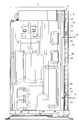
- the inside of the outdoor unit Co shown in FIG. 2 is divided into a blower chamber 11 and a machine chamber 12 by a partition plate 7.
- the blower chamber 11 is a chamber for storing the heat exchanger 2 and the fan 5.
- An outdoor heat exchanger 2 bent in an L shape as viewed from above is provided on the left side and the rear of the inner and outer peripheral portions of the air blowing chamber 11 (see FIG. 2).
- a fan 5 for sending air from the rear of the outdoor unit Co to the outdoor heat exchanger 2 is disposed.
- an accumulator 3, a compressor 4 and so on, which constitute a refrigeration cycle, are connected via a pipe h1.
- An opening 1k is formed to suck outside air into the interior of the outdoor unit Co from the rear of the outdoor unit Co, exchange heat with the outdoor heat exchanger 2, and discharge the air forward.
- the opening 1k is configured to have a radial and circular grid 1k1.
- an electric goods box 6 in which a control unit such as a fan motor (not shown) for driving the fan 5 or an inverter device for controlling the compressor 4 is stored.
- the outdoor unit Co is installed outdoors and is exposed to wind and rain, so when it rains or a typhoon, moisture gets into the air blowing chamber 11 from the opening 1k (see FIG. 1).
- the machine room 12 is a room in which the machine element and the like of the air conditioner C are disposed, it is not desirable that moisture infiltrates. Therefore, the boundary between the air blowing chamber 11 and the machine room 12 needs a waterproof structure.
- the outdoor heat exchanger 2 shown in FIG. 3 is configured such that a heat exchanger pipe 2p, through which a refrigerant flows, penetrates substantially vertically and is in contact with a large number of fins.
- the refrigerant flowing through the heat exchanger pipe 2p exchanges heat with the outside air sucked from the rear of the outdoor unit Co via the pipe wall of the heat exchanger pipe 2p and a large number of fins whose heat transfer (table) area is expanded.
- Ru A heat exchanger side plate 13 for attaching the outdoor heat exchanger 2 to the rear plate 1b (see FIG. 1) of the outer cabinet 1 is fixed to the right end portion 2r (see FIG. 3) of the outdoor heat exchanger 2. .
- the partition plate 7 is a member that divides the inside of the outdoor unit Co into the air blowing chamber 11 (left side in FIG. 2) and the machine room 12 (right side in FIG. 2).
- the central plate 7 a is screwed to the base 1 s of the lower outer cabinet 1, and the fixing plate 7 c (see FIG. 5B) of the partition plate 7 is the heat exchanger side plate 13 on the rear. It is positioned by and fixed by a screw n1.
- FIG. 5A The front view which looked at the partition plate 7 from I direction of FIG. 3 at FIG. 5A is shown.
- the figure which looked at FIG. 5A partition plate 7 from upper direction in FIG. 5B is shown.
- FIG. 5C shows an enlarged view of a part III of FIG. 5B.
- the partition plate 7 is sheet-formed using a steel plate. As shown in FIG. 5A, the partition plate 7 has a flat plate-like central plate 7a, and a diagonal plate 7b which is bent from the central plate 7a and extends toward the right end 2r of the outdoor heat exchanger 2. . At a rear portion of the oblique plate 7b, a fixing plate 7c for fixing the partition plate 7 to the rear heat exchanger side plate 13 is formed extending in the vertical direction.
- a first flange plate 7d extending rearward and a rear attachment portion 7e extending rearward from the first flange plate 7d are formed in a pair vertically (see FIG. 5A). ing. Screw insertion holes 7e1 through which the screws n1 are respectively inserted are formed in the pair of rear attachment portions 7e.
- a second flange plate 7f is continuously formed by bending laterally at the rear of the first flange plate 7d.
- the pair of rear mounting portions 7e of the partition plate 7 shown in FIG. 5A play a role of fixing the partition plate 7 to the heat exchanger side plate 13 fixed to the outdoor heat exchanger 2 with the screw n1 (see FIG. 4A).
- the second flange plate 7f of the partition plate 7 has a function of positioning and fixing the partition plate 7 against the mountain-shaped projections 14 of the heat exchanger side plate 13 fixed to the outdoor heat exchanger 2 or in contact therewith. I am responsible.
- the heat exchanger side plate 13 shown in FIGS. 4A and 4B is a member for fixing the outdoor heat exchanger 2 to the rear plate 1b (see FIG. 1) of the outer cabinet 1 of the outdoor unit Co.
- FIG. 7B shows a view taken in the direction of arrow IV in FIG. 7A
- FIG. 7C shows a view taken in the direction of arrow V in FIG. 7A
- FIG. 7D shows an enlarged perspective view of part VI of FIG. 7A.
- the heat exchanger side plate 13 shown in FIGS. 7A and 7B is cut in the vicinity of the center and arranged side by side in the left and right directions because it is long in the vertical direction of the drawing.
- the heat exchanger side plate 13 is sheet-formed using a steel plate.
- the heat exchanger side plate 13 has a heat exchange mounting plate 13a and a cabinet mounting plate 13b which is continuously bent to the heat exchange mounting plate 13a.
- a mounting portion 13b1 having a female screw 13b2 screwed to the rear plate 1b is formed on the cabinet mounting plate 13b so as to protrude outward.
- the female screw 13b2 of the mounting portion 13b1 is formed by burring.
- the female screw 13b2 of the mounting portion 13b1 of the cabinet mounting plate 13b is screwed with a screw inserted through the rear plate 1b of the outer cabinet 1.
- the outdoor heat exchanger 2 is fixed to the rear plate 1 b of the outer cabinet 1 via the heat exchanger side plate 13.
- FIG. 7A shows the case where two female screws 13a1 are formed.
- a pipe mounting hole 13a2 is formed in which a plurality of heat exchanger pipes 2p are inserted.
- the heat exchange mounting plate 13a is formed with a convex fixing hole 13a3 to which the heat exchanger pipe 2p is fixed.
- the convex fixing holes 13a3 are formed by burring with a diameter slightly smaller than that of the heat exchanger pipe 2p so that the heat exchanger pipe 2p can be inserted, diameter-increased and fixed.
- the mountain-shaped protrusion 14 is formed in multiple numbers by the heat exchanger attachment plate 13a.
- the end surface 14 t of the chevron 14 abuts against the second flange plate 7 f of the partition plate 7 and plays a role of positioning and waterproofing.
- the chevrons 14 are formed in a chevron in which the meat of the heat exchanger side plate 13 is continuous without breaks.
- the mountain-shaped projections 14 are disposed between the pipe mounting hole 13a2 and the adjacent pipe mounting hole 13a2, or between the pipe mounting hole 13a2 and the fixing hole 13a3.
- the chevrons 14 are formed into a chevron continuously with no break in the heat of the heat exchanger side plate 13 to form a waterproof structure.
- the chevrons 14 are drawn by a first mold having a chevron convex shape and a second mold having a chevron concave shape.
- the outdoor heat exchanger 2 is a fin and tube type heat exchanger.
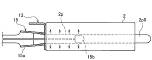
- FIGS. 8A to 8C show schematic manufacturing steps schematically showing the process of fixing the heat exchanger pipe 2p to the fixing holes 13a3 of the heat exchanger side plate 13 with the fins 2f.
- the process of fixing the heat exchanger pipe 2p to the fins 2f forming the outdoor heat exchanger 2 and the fixing holes 13a3 of the heat exchanger side plate 13 is performed as follows.
- pipe insertion holes 2f1 having substantially the same diameter as the fixing holes 13a3 of the heat exchanger side plate 13 are formed.
- the pipe insertion holes 21f of the plurality of fins 2f and the fixing holes 13a3 of the heat exchanger side plate 13 are positioned at the same position so that the heat exchanger pipe 2p can be inserted. .
- a pipe blank 2p0 having a diameter slightly smaller than that of the heat exchanger pipe 2p is inserted into the pipe insertion holes 2f1 of the plurality of fins 2f positioned and the fixing holes 13a3 of the heat exchanger side plate 13.
- the expansion support 15a of the expansion jig 15 for expanding the base pipe 2p to the heat exchanger pipe 2p, the pipe insertion holes 21f of the plurality of fins 2f, and the heat exchanger side plate 13 It is applied around the pipe base 2p0 inserted into the fixing hole 13a3.
- an expansion head 15b for expanding the pipe base pipe 2p is hydraulically stored and retracted. Subsequently, as shown in FIG. 8C, the expanded head 15b accommodated in the expanded support 15a advances inside the pipe base 2p to expand the diameter of the pipe base 2p.
- the fixing holes 13a3 of the heat exchanger side plate 13 and the pipe insertion holes 2f1 of the plurality of fins 2f are plastically deformed, and the heat exchanger pipe 2p is formed with the fixing holes 13a3 of the heat exchanger side plate 13 It is fixed to the pipe insertion hole 2f1 of the fin 2f.
- the mountain-shaped projections 14 of the heat exchanger side plate 13 are formed apart from the fixing holes 13 a 3 of the heat exchanger side plate 13 so as not to abut on the expanded support 15 a of the pipe expansion jig 15. That is, the heat exchanger side plate 13 is disposed at the middle side or middle between the fixing holes 13a3 (see FIG. 4A).
- the heat exchanger side plate 13 contacts the partition plate 7, and the end surface 14 t of the mountain-shaped protrusion 14 of the heat exchanger side plate 13 is the partition plate 7.
- the heat exchanger side plate 13 and the partition plate 7 are positioned in abutment or contact with the second flange plate 7 f. Then, the screw n1 inserted through the screw insertion hole 7e1 (see FIG. 5A) of the fixing plate 7c of the partition plate 7 is screwed to the female screw 13a1 (see FIG. 7A) of the heat exchanger side plate 13, and the partition plate 7 is thermally It is fixed to the exchanger side plate 13.
- heat exchanger side panel 13 is a shell cabinet It is fixed to the back plate 1b of 1.
- the heat exchanger side plate 13 is fixed to the outdoor heat exchanger 2.
- the central plate 7 a is screwed to the base 1 s (see FIG. 3) of the lower outer cabinet 1.
- a structure that fixes without gaps is required.
- the second flange plate 7f of the partition plate 7 must be prevented from coming into contact with the heat exchanger pipe 2p of the outdoor heat exchanger 2 for damage. Therefore, in the outdoor unit Co, the heat exchanger side plate 13 is brought into contact with the partition plate 7, and the end face 13t of the mountain-shaped projection 14 is abutted against or brought into contact with the second flange plate 7f of the partition plate 7 The exchanger side plate 13 and the partition plate 7 are positioned. Thus, a gap (distance) is reliably secured between the second flange plate 7f of the partition plate 7 and the heat exchanger pipe 2p.
- the partition plate 7 and the heat exchanger side plate 13 can be fixed without a gap, and the second flange plate 7f of the partition plate 7 is fixed so as not to damage the heat exchanger pipe 2p. It enables coexistence with the structure that can be done.
- the arrangement of the chevrons 14 is positioned on the intermediate side of the heat exchanger pipe 2p and the heat exchanger pipe 2p, so that the heat exchanger pipe is manufactured in the process of manufacturing the outdoor heat exchanger 2.
- the arrangement is such that interference with the 2p pipe expansion jig 15 (see FIGS. 8B and 8C) can be prevented.
- the height H C of the end surface 14 t of the mountain-shaped protrusion 14 with respect to the extending surface 13 a 1 of the heat exchanger side plate 13 on the air blowing chamber side is the second flange plate 7 f of the partition plate 7. It can not be hit until it reaches to.
- FIG. 9 is a schematic view of the positional relationship between the second flange plate 107 f of Comparative Example 1 and the end surface 114 t of the mountain-shaped protrusion 114 of the heat exchanger side plate 113.
- the height H C of the end faces 114t chevron protrusion 114 is less than the radius of curvature R S of the bending of the second flange plate 107f
- the end surface 14t of the chevron protrusion 14 second flange plate It can not hit 107f.
- the height H C of the chevrons 14 is set to a value larger than the curvature radius R S of bending for forming the second flange plate 7 f of the partition plate 7 (R S ⁇ H C ).
- the end face 14t of the mountain-shaped protrusion 14 abuts on the second flange plate 7f of the partition plate 7 in parallel.
- the height H C of the end face 14 t of the mountain-shaped projection 14 shown in FIG. 6 is the height H based on the extending surface 13 a 1 of the second flange plate 7 f of the partition plate 7 on the air blowing chamber side of the exchanger side plate 13. If it is larger than S , a gap is formed between the mountain-shaped projection 14 and the second flange plate 7 f of the partition plate 7, which causes the entry of rainwater.
- FIG. 10 is a schematic view of the positional relationship between the second flange plate 207 f of the partition plate 207 of Comparative Example 2 and the end surface 214 t of the mountain-shaped protrusion 214 of the heat exchanger side plate 213.
- H C the height of the mountain-shaped protrusion 214
- H S the height of the second flange plate 207 f of the partition plate 207
- a gap is formed between the plate 207 and the second flange plate 207f, there is a possibility that rain water may intrude into the machine chamber 12 from the blowing chamber 11 (arrow ⁇ 1 in FIG. 10).
- the height H C of the chevrons 14 is made smaller than the height Hs of the second flange plate 7 f of the partition plate 7, that is, a smaller value (H C ⁇ H S ) and has a structure to prevent the intrusion of rainwater.
- the heat exchanger side plate 13 of the outdoor heat exchanger 2 comes into contact with the partition plate 7 and the end face 14 t of the mountain-shaped projection 14 of the heat exchanger side plate 13 abuts against the partition plate 7 It is supposed to be fixed.
- the end face 14 t of the mountain-shaped projection 14 of the heat exchanger side plate 13 is in contact with the partition plate 7 and fixed. Therefore, as shown in FIG. 6, the distance between the second flange plate 7f of the partition plate 7 and the heat exchanger pipe 2p is reliably ensured. Accordingly, the approach of the second flange plate 7f of the partition plate 7 to the heat exchanger pipe 2p is suppressed. Therefore, the structure which the 2nd flange plate 7f of the partition plate 7 and the heat exchanger pipe 2p do not contact is realizable.
- a chevron-shaped projection 14 (see FIG. 4A) is disposed in the vicinity of the fixing portion 7k for fastening and fixing the partition plate 7 and the heat exchanger side plate 13 with the screw n1.
- An end surface 14 t of the mountain-shaped projection 14 of the side surface plate 13 is in contact with the second flange plate 7 f of the partition plate 7 in parallel.
- the mountain-shaped projection 14 is disposed at the middle side or middle between the heat exchanger pipe 2p of one of the refrigerants flowing in the refrigeration cycle and the other heat exchanger pipe 2p, the pipe expanding operation of the heat exchanger pipe 2p Can be done without delay.
- the structure which can be fixed so that there may be no gap in the junction part of heat exchanger side plate 13 and partition plate 7, and the 2nd flange plate 7f of partition plate 7 contacting heat exchanger pipe 2p and being damaged It is possible to realize a structure that can be accurately positioned and fixed so that there is no
- the chevrons 14 are illustrated. However, if the projections whose thickness increases in the thickness direction at the end edge of the partition plate 7 are continuous, the end surfaces that abut or contact the partition plate 7 shown in FIG.
- the shape of the protrusion 34 having an end face 24t that abuts on or contacts the partition plate 7 shown in FIG. 12 may be used, and the shape is not limited as long as the shape of the protrusion.
- the protrusions 24 and 34 of the modification examples 1 and 2 are shown to FIG. 11, FIG. 12, respectively.
- partition plate 7 was manufactured using a steel plate was demonstrated in the said embodiment, you may be manufactured using materials other than a steel plate, such as high-strength plastic.
Landscapes
- Engineering & Computer Science (AREA)
- Chemical & Material Sciences (AREA)
- Combustion & Propulsion (AREA)
- Mechanical Engineering (AREA)
- General Engineering & Computer Science (AREA)
- Other Air-Conditioning Systems (AREA)
Abstract
本発明の空気調和機(C)は、室内機(Ci)と、室外機(Co)とを具備し、室外機(Co)は、外気を取り入れて熱交換後の外気を吐き出す送風室(11)と冷凍サイクルの機械要素(3、4)が収容される機械室(12)とを区分けする仕切り板(7)と、室外機(Co)に収容され、外気と熱交換を行う室外熱交換器(2)と、室外熱交換器(2)に固定され、前記室外機(Co)の外郭を形成する筐体(1)に固定され室外熱交換器(2)を筐体(1)に固定する熱交換器側面板13とを備え、熱交換器側面板(13)は、凸形状に肉が連続して形成される固定用凸部(14)を端部に有し、熱交換器側面板(13)と仕切り板(7)とが接触されるとともに、固定用凸部(14)の端縁(14t)が、仕切り板(7)に接触して固定されている。
Description
本発明は、空気調和機に関する。
従来、空気調和機の室外機は、熱交換器やファンを格納するための送風室と圧縮機や冷媒配管を格納するための機械室とに分割されており、仕切り板により区分けされている。
ここで、熱交換器を室外機の外郭キャビネット部品に固定するための熱交換器側面板と仕切り板との接合部では、送風室側から機械室への雨水の侵入を防止するために隙間なく熱交換器側面板と仕切り板とを固定する構造が必要である。
ここで、熱交換器を室外機の外郭キャビネット部品に固定するための熱交換器側面板と仕切り板との接合部では、送風室側から機械室への雨水の侵入を防止するために隙間なく熱交換器側面板と仕切り板とを固定する構造が必要である。
加えて、前記接合部を構成する仕切り板の端部フランジ面が、熱交換器を構成して冷媒が流れる熱交換器パイプに接触してパイプを損傷することがないようにしなければならない。そこで、仕切り板の端部フランジ面と熱交換器パイプのとの間に隙間を確保できるように、熱交換器側面板と仕切り板とを精度良く位置決めして固定できる構造とを両立する必要がある。
上述の接触防止構造に類似の技術として特許文献1があり、仕切り板に係る技術として特許文献2がある。
特許文献1には以下の接触防止構造が構成が記載されている。
特許文献1には以下の接触防止構造が構成が記載されている。
電気的接続用のリード線を樹脂部品及び板金製の防火カバーB12に接触し引き回しを行う構造をもつ空気調和機の室外機において、前記リード線が防火カバーB12のエッジ部に触れないようにするための絞り形状(ビード)11bを板金性の防火カバーA11に設けている。折り曲げする防火カバーB12の形状は、最小限の大きさで材料コストの上昇を抑え、かつ部品点数や組立工数の削減を図りながら、リード線エッジ部への接触を防止している。
特許文献2には、以下の仕切り板に係る技術が記載されている。
段落0041には、「この第1取付板13は、板面方向が放熱フィン15と平行に配置され、その板面の端縁が冷媒管16の管長方向で外側にL字形に折り曲げられて取付リブ17を構成し、両リブ17にキャビネットの側面パネル8,9および仕切板3に固定するためのネジ孔19が形成されている。また、第1取付板13は、その背面側の端縁の一部が切欠き形成されると共に、その切欠き部の壁面の一部がリブ状に折り曲げ形成され、温度センサー等のセンサーを取り付ける取付部20とされている。」との記載がある。
段落0041には、「この第1取付板13は、板面方向が放熱フィン15と平行に配置され、その板面の端縁が冷媒管16の管長方向で外側にL字形に折り曲げられて取付リブ17を構成し、両リブ17にキャビネットの側面パネル8,9および仕切板3に固定するためのネジ孔19が形成されている。また、第1取付板13は、その背面側の端縁の一部が切欠き形成されると共に、その切欠き部の壁面の一部がリブ状に折り曲げ形成され、温度センサー等のセンサーを取り付ける取付部20とされている。」との記載がある。
ところで、送風室側から機械室への雨水の侵入の防止に関しては、熱交換器側面板と仕切り板との接合部にクッション材を適用して防水を図っている製品がある。しかし、この構成では、クッション材の材料コストと、クッション材の組立てコストとが嵩み、製造コストの上昇に繋がる。
一方、仕切り板の端部フランジ面が熱交換器パイプに接触して熱交換器パイプが損傷するという課題については、熱交換器パイプと熱交換器側面板と仕切り板との接合部との間の距離を大きくして、仕切り板の端部フランジ面が熱交換器パイプに接触しない構造にしたものがある。しかし、この構成では、室外機が大型化する。そのため、室外機が大型化して部品が大きくなることから、部品の材料コストが嵩むという問題がある
本発明は上記実状に鑑み創案されたものであり、室外機において、仕切り板と熱交換器側面板の接合部の防水構造と仕切り板と熱交換器パイプとが非接触となる空気調和機の提供を目的とする。
前記課題を解決するため、本発明の空気調和機は、室内機と、室外機とを具備し、前記室外機は、外気を取り入れて熱交換後の外気を吐き出す送風室と冷凍サイクルの機械要素が収容される機械室とを区分けする仕切り板と、前記室外機に収容され、外気と熱交換を行う室外熱交換器と、前記室外熱交換器に固定され、前記室外機の外郭を形成する筐体に固定され前記室外熱交換器を前記筐体に固定する熱交換器側面板とを備え、前記熱交換器側面板は、凸形状に肉が連続して形成される固定用凸部を端部に有し、前記熱交換器側面板と前記仕切り板とが接触されるとともに、前記固定用凸部の端縁が、前記仕切り板に接触して固定されている。
本発明によれば、室外機において、仕切り板と熱交換器側面板の接合部の防水構造と仕切り板と熱交換器パイプとが非接触となる空気調和機を提供できる。
以下、本発明の実施形態について、適宜図面を参照しながら詳細に説明する。
本発明は、送風室11(図3参照)と機械室12とを仕切る仕切り板7と熱交換器側面板13(図3参照)との接合部で隙間がないよう固定できる構造と、仕切り板7が熱交換器パイプ2p(図4B参照)に接触して熱交換器パイプ2pを損傷することがないように固定できる構造とを両立する。
本発明は、送風室11(図3参照)と機械室12とを仕切る仕切り板7と熱交換器側面板13(図3参照)との接合部で隙間がないよう固定できる構造と、仕切り板7が熱交換器パイプ2p(図4B参照)に接触して熱交換器パイプ2pを損傷することがないように固定できる構造とを両立する。
図1に、本発明に係る実施形態の空気調和機Cの室内機Ciと室外機Coを示す。
実施形態の空気調和機Cは、室内機Ciと室外機Coとを具備している。
実施形態の空気調和機Cは、室内機Ciと室外機Coとを具備している。
室内機Ciは屋内に設置され、屋内の空気調和を行う。
<室外機Co>
室外機Coは、屋外に設置され、その内部に冷凍サイクルの主な機械要素等が格納されている。
室外機Coは、外郭キャビネット1により外郭が形成されている。
室外機Coは、屋外に設置され、その内部に冷凍サイクルの主な機械要素等が格納されている。
室外機Coは、外郭キャビネット1により外郭が形成されている。
図2に、室外機Coの外郭キャビネット1の前板1mと上板1uを外した状態を示す。図3に、室外機Coの外郭キャビネット1を外し、送風室11と機械室12の内部の機器を取り外した状態を示す。図4Aに、図3のI方向から見た図を示す。図4Bに、図3のII部の拡大斜視図を示す。
室外機Co(図2参照)と室内機Ci(図1参照)の内部には、冷媒が流れる配管2で接続される冷凍サイクルが構成されている。
室外機Co(図2参照)と室内機Ci(図1参照)の内部には、冷媒が流れる配管2で接続される冷凍サイクルが構成されている。
図2に示す室外機Coの内部は、送風室11と機械室12とに、仕切り板7によって分割されている。
送風室11は、熱交換器2やファン5を格納するための室である。
送風室11は、熱交換器2やファン5を格納するための室である。
送風室11(図2参照)の内外周部の向かって左側部および後部には、上方から見てL字状に折れ曲がった室外熱交換器2が設けられている。後部に配置された室外熱交換器2の前方には、室外機Coの後方から室外熱交換器2に空気を送るためのファン5が配置されている。
機械室12の内部には、冷凍サイクルを構成するアキュムレータ3、圧縮機4等が配管h1を介して連結されている
図1に示すように、外郭キャビネット1の前板1mには、ファン5で外気を室外機Coの後方から室外機Coの内部に吸込み、室外熱交換器2と熱交換した後に前方に向けて排出するための開口1kが形成されている。開口1kは、放射状および円形状を成す格子1k1を有して構成されている。
図1に示すように、外郭キャビネット1の前板1mには、ファン5で外気を室外機Coの後方から室外機Coの内部に吸込み、室外熱交換器2と熱交換した後に前方に向けて排出するための開口1kが形成されている。開口1kは、放射状および円形状を成す格子1k1を有して構成されている。
図2に示す室外機Coの右上には、ファン5を駆動するファンモータ(図示せず)や圧縮機4を制御するインバータ装置等の制御部が格納される電気品箱6が配設されている。
室外機Coは、屋外に設置されて風雨に晒されるため、雨天や台風の際には、開口1k(図1参照)から水分が送風室11の内部に入り込む。上記したように、機械室12は、空気調和機Cの機械要素等が配置される室のため、水分が浸入することは望ましくない。そこで、送風室11と機械室12との境界は防水構造が必要となっている。
室外機Coは、屋外に設置されて風雨に晒されるため、雨天や台風の際には、開口1k(図1参照)から水分が送風室11の内部に入り込む。上記したように、機械室12は、空気調和機Cの機械要素等が配置される室のため、水分が浸入することは望ましくない。そこで、送風室11と機械室12との境界は防水構造が必要となっている。
図3に示す室外熱交換器2は、冷媒が流れる熱交換器パイプ2pが多数のフィンにほぼ垂直に貫通して接触して構成されている。熱交換器パイプ2pを流れる冷媒は、熱交換器パイプ2pの管肉と伝熱(表)面積が拡大される多数のフィンを介して、室外機Coの後方から吸い込まれた外気と熱交換される。
室外熱交換器2の右端部2r(図3参照)には、室外熱交換器2を外郭キャビネット1の後板1b(図1参照)に取り付けるための熱交換器側面板13が固定されている。
室外熱交換器2の右端部2r(図3参照)には、室外熱交換器2を外郭キャビネット1の後板1b(図1参照)に取り付けるための熱交換器側面板13が固定されている。
<仕切り板7>
前記したように、仕切り板7は、室外機Coの内部を送風室11(図2の左側)と機械室12(図2の右側)とに区分けする部材である。
前記したように、仕切り板7は、室外機Coの内部を送風室11(図2の左側)と機械室12(図2の右側)とに区分けする部材である。
図3に示すように、仕切り板7は、中央板7aが下方の外郭キャビネット1のベース1sとネジ止めされ、仕切り板7の固定板7c(図5B参照)が後方の熱交換器側面板13に位置決めされてねじn1で固定されている。
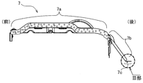
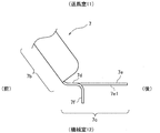
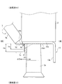
図5Aに、仕切り板7を図3のI方向から見た正面図を示す。図5Bに、図5A仕切り板7を上方から見た図を示す。図5Cに、図5BのIII部拡大図を示す。図6に、仕切り板7と室外熱交換器2に固定される熱交換器側面板13との固定構造を上方から見た図を示す。
仕切り板7は、鋼板を用いて板金成形されている。図5Aに示すように、仕切り板7は、平板状の中央板7aと、中央板7aから曲って室外熱交換器2の右端部2rに向かって延在する斜め板7bとを有している。斜め板7bの後部には、仕切り板7を後方の熱交換器側面板13に固定するための固定板7cが上下方向に延在して形成されている。
図5A、図5Cに示す仕切り板7の固定板7cは、後方に延びる第1フランジ板7dと、第1フランジ板7dから後方に延びる後取付部7eが上下に一対(図5A参照)形成されている。一対の後取付部7eには、それぞれねじn1が挿通するねじ挿通孔7e1が形成されている。
図5Cに示すように、第1フランジ板7dの後部には側方に折れ曲がって第2フランジ板7fが連続して形成されている。
図5Cに示すように、第1フランジ板7dの後部には側方に折れ曲がって第2フランジ板7fが連続して形成されている。
図5Aに示す仕切り板7の一対の後取付部7eは、仕切り板7を室外熱交換器2に固定される熱交換器側面板13にねじn1(図4A参照)で固定する役割を担っている。
仕切り板7の第2フランジ板7fは、仕切り板7を室外熱交換器2に固定される熱交換器側面板13の山型突起14に突き当ててまたは接触して位置決めして固定する役割を担っている。
仕切り板7の第2フランジ板7fは、仕切り板7を室外熱交換器2に固定される熱交換器側面板13の山型突起14に突き当ててまたは接触して位置決めして固定する役割を担っている。
<熱交換器側面板13>
図4A、図4Bに示す熱交換器側面板13は、室外熱交換器2を室外機Coの外郭キャビネット1の後板1b(図1参照)に固定するための部材である。
図4A、図4Bに示す熱交換器側面板13は、室外熱交換器2を室外機Coの外郭キャビネット1の後板1b(図1参照)に固定するための部材である。
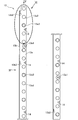
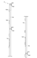
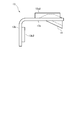
図7Aに、図3のI方向から見た熱交換器側面板13の正面図を示す。図7Bに、図7AのIV方向矢視図を示し、図7Cに、図7AのV方向矢視図を示す。図7Dに、図7AのVI部の拡大斜視図を示す。なお、図7A、図7Bに示す熱交換器側面板13は紙面縦方向に長いため中央付近で切断して左右2つに並べて示している。
熱交換器側面板13は、鋼板を用いて、板金成形されている。
熱交換器側面板13は、鋼板を用いて、板金成形されている。
熱交換器側面板13は、熱交取付板13aと、熱交取付板13aに連続して曲って形成されるキャビネット取付板13bとを有している。
図7Bに示すように、キャビネット取付板13bには、後板1bにねじ止めされる雌ねじ13b2を有する取付部13b1が外側に突出して形成されている。取付部13b1の雌ねじ13b2はバーリング加工によって形成されている。キャビネット取付板13bの取付部13b1の雌ねじ13b2は、外郭キャビネット1の後板1bを挿通したねじが螺合される。これによって、室外熱交換器2が熱交換器側面板13を介して外郭キャビネット1の後板1bに固定されている。
一方、熱交取付板13aには、仕切り板7の固定板7cのねじ挿通孔7e1を挿通したねじn1(図4A参照)がネジ止めされる雌ねじ13a1が複数バーリング加工によって形成されている。図7Aでは、雌ねじ13a1が2箇所形成された場合を示す。
また、熱交取付板13aには、複数の熱交換器パイプ2pが挿通されるパイプ取付穴13a2が形成されている。また、熱交取付板13aには、熱交換器パイプ2pが固定される凸形の固定用孔13a3が形成されている。凸形の固定用孔13a3は、熱交換器パイプ2pが挿通して拡径されて固定されるように、熱交換器パイプ2pより若干小さい径をもってバーリング加工で形成されている。
そして、図7A、図7C、図7Dに示すように、熱交取付板13aには、山型突起14が複数形成されている。後記の図6に示すように、山型突起14は、その端面14tが仕切り板7の第2フランジ板7fに突き当たり、位置決めと防水構造の役割を担っている。
山型突起14は、熱交換器側面板13の肉が切れ目なく連続して山型に形成されている。山型突起14は、パイプ取付穴13a2と隣接するパイプ取付穴13a2との間や、パイプ取付穴13a2と固定用孔13a3との間に配置されている。山型突起14を、熱交換器側面板13の肉が切れ目なく連続して山型に形成することで防水構造としている。
山型突起14は熱交換器側面板13を板金成形する際に、山型凸形状を有する第1金型と山型凹形状を有する第2金型とにより絞り成形される。
<室外熱交換器2>
室外熱交換器2はフィンアンドチューブ方式の熱交換器である。
室外熱交換器2はフィンアンドチューブ方式の熱交換器である。
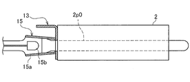
図8A~図8Cに、熱交換器パイプ2pをフィン2fと熱交換器側面板13の固定用孔13a3に固定する工程の概略の製作工程模式図を示す。
室外熱交換器2を形成するフィン2fと熱交換器側面板13の固定用孔13a3に熱交換器パイプ2pを固定する工程は以下のように行われる。
室外熱交換器2を形成するフィン2fと熱交換器側面板13の固定用孔13a3に熱交換器パイプ2pを固定する工程は以下のように行われる。
複数のフィン2fには、熱交換器側面板13の固定用孔13a3とほぼ同径のパイプ挿通孔2f1が形成されている。
まず、図8Aに示すように、複数のフィン2fのパイプ挿通孔21fと熱交換器側面板13の固定用孔13a3が熱交換器パイプ2pが挿入できるように同位置に並ぶように位置決めされる。
まず、図8Aに示すように、複数のフィン2fのパイプ挿通孔21fと熱交換器側面板13の固定用孔13a3が熱交換器パイプ2pが挿入できるように同位置に並ぶように位置決めされる。
続いて、位置決めされた複数のフィン2fのパイプ挿通孔2f1と熱交換器側面板13の固定用孔13a3に、熱交換器パイプ2pよりやや径が小さいパイプ素管2p0が挿通される。
続いて、図8Bに示すように、パイプ素管2pを熱交換器パイプ2pに拡管するための拡管冶具15の拡管サポート15aを、複数のフィン2fのパイプ挿通孔21fと熱交換器側面板13の固定用孔13a3とに挿通されたパイプ素管2p0の周りに当てる。
続いて、図8Bに示すように、パイプ素管2pを熱交換器パイプ2pに拡管するための拡管冶具15の拡管サポート15aを、複数のフィン2fのパイプ挿通孔21fと熱交換器側面板13の固定用孔13a3とに挿通されたパイプ素管2p0の周りに当てる。
なお、拡管冶具15の拡管サポート15aの内部には、パイプ素管2pを拡管するための拡管ヘッド15bが油圧により進退自在に格納されている。
続いて、図8Cに示すように、拡管サポート15aに収容される拡管ヘッド15bがパイプ素管2pの内部に進行してパイプ素管2pが拡径される。こうして、熱交換器側面板13の固定用孔13a3と複数のフィン2fのパイプ挿通孔2f1が塑性変形して、熱交換器パイプ2pが、熱交換器側面板13の固定用孔13a3と複数のフィン2fのパイプ挿孔通2f1に固定される。
続いて、図8Cに示すように、拡管サポート15aに収容される拡管ヘッド15bがパイプ素管2pの内部に進行してパイプ素管2pが拡径される。こうして、熱交換器側面板13の固定用孔13a3と複数のフィン2fのパイプ挿通孔2f1が塑性変形して、熱交換器パイプ2pが、熱交換器側面板13の固定用孔13a3と複数のフィン2fのパイプ挿孔通2f1に固定される。
そのため、熱交換器側面板13の山型突起14は、拡管冶具15の拡管サポート15aに当接しないように、熱交換器側面板13の固定用孔13a3から離膈して形成されている。つまり、熱交換器側面板13の固定用孔13a3間の中間側または中間に配置されている(図4A参照)。
<送風室11と機械室12との境界部の構成>
図3に示す送風室11と機械室12との境界部の構成について説明する。
送風室11と機械室12との境界部は、仕切り板7と熱交換器側面板13とを固定することにより形成されている。
図3に示す送風室11と機械室12との境界部の構成について説明する。
送風室11と機械室12との境界部は、仕切り板7と熱交換器側面板13とを固定することにより形成されている。
具体的には、上面拡大図の図6に示すように、熱交換器側面板13が仕切り板7に接触するとともに、熱交換器側面板13の山型突起14の端面14tが仕切り板7の第2フランジ板7fに突き当てられまたは接触して、熱交換器側面板13と仕切り板7とが位置決めされる。そして、仕切り板7の固定板7cのねじ挿通孔7e1(図5A参照)を挿通したねじn1が、熱交換器側面板13の雌ねじ13a1(図7A参照)にねじ止めされ、仕切り板7が熱交換器側面板13に固定されている。
そして、外郭キャビネット1の後板1bを挿通したねじが、熱交換器側面板13の取付部13b1の雌ねじ13b2(図7B、図7D参照)に螺合され、熱交換器側面板13が外郭キャビネット1の後板1bに固定される。そして、熱交換器側面板13は室外熱交換器2に固定される。
一方、仕切り板7は、中央板7aが下方の外郭キャビネット1のベース1s(図3参照)とネジ止めされる。
ここで、室外機1においては、送風室11と機械室12との境界となる仕切り板7と熱交換器側面板13との接合部で、送風室11からの機械室12への雨水の侵入を防止するために隙間なく固定する構造が必要である。
ここで、室外機1においては、送風室11と機械室12との境界となる仕切り板7と熱交換器側面板13との接合部で、送風室11からの機械室12への雨水の侵入を防止するために隙間なく固定する構造が必要である。
また、図6に示すように、仕切り板7の第2フランジ板7fが室外熱交換器2の熱交換器パイプ2pに接触して損傷することがないようにしなければならない。
そこで、本室外機Coでは、熱交換器側面板13を仕切り板7に接触させるとともに、山型突起14の端面13tを仕切り板7の第2フランジ板7fに突き当てるまたは接触させることにより、熱交換器側面板13と仕切り板7とを位置決めしている。これにより、仕切り板7の第2フランジ板7fと熱交換器パイプ2pとの間に隙間(距離)を確実に確保している。
そこで、本室外機Coでは、熱交換器側面板13を仕切り板7に接触させるとともに、山型突起14の端面13tを仕切り板7の第2フランジ板7fに突き当てるまたは接触させることにより、熱交換器側面板13と仕切り板7とを位置決めしている。これにより、仕切り板7の第2フランジ板7fと熱交換器パイプ2pとの間に隙間(距離)を確実に確保している。
この構造により、仕切り板7と熱交換器側面板13とが隙間なく固定できる構造と、仕切り板7の第2フランジ板7fが熱交換器パイプ2pに接触して損傷することがないように固定できる構造との両立を可能としている。
また、図4Aに示すように、山型突起14の配置は、熱交換器パイプ2pと熱交換器パイプ2pの中間側に位置することにより、室外熱交換器2の製作工程で熱交換器パイプ2pの拡管冶具15(図8B、図8C参照)との干渉を防止できる配置としている。
また、図6に示すように、山型突起14の端面14tの熱交換器側面板13の送風室側の延在面13a1を基準とする高さHCが仕切り板7の第2フランジ板7fまで届かないと突き当てできない。
図9に、比較例1の第2フランジ板107fと熱交換器側面板113の山型突起114の端面114tとの位置関係の模式図を示す。
例えば、図9に示すように、山型突起114の端面114tの高さHCが第2フランジ板107fの曲げの曲率半径RSより低い場合、山型突起14の端面14tを第2フランジ板107fに突き当てることができない。
例えば、図9に示すように、山型突起114の端面114tの高さHCが第2フランジ板107fの曲げの曲率半径RSより低い場合、山型突起14の端面14tを第2フランジ板107fに突き当てることができない。
そこで、山型突起14の高さHCは、図6に示すように、仕切り板7の第2フランジ板7fを構成するための曲げの曲率半径RSよりも大きい値とする(RS<HC)。これにより、仕切り板7の第2フランジ板7fに山型突起14の端面14tが並行に突き当たる構造としている。
また、図6に示す山型突起14の端面14tの高さHCが仕切り板7の第2フランジ板7fの交換器側面板13の送風室側の延在面13a1を基準とする高さHSより大きい場合、山型突起14と仕切り板7の第2フランジ板7fとの間に隙間ができるため、雨水の侵入の要因となる。
図10に、比較例2の仕切り板207の第2フランジ板207fと熱交換器側面板213の山型突起214の端面214tとの位置関係の模式図を示す。
例えば、図10に示すように、山型突起214の高さHCが仕切り板207の第2フランジ板207fの高さHSより大きい(HC>HS)場合、山型突起214と仕切り板207の第2フランジ板207fとの間に隙間ができるため、雨水が送風室11から機械室12に侵入する(図10の矢印α1)おそれがある。
例えば、図10に示すように、山型突起214の高さHCが仕切り板207の第2フランジ板207fの高さHSより大きい(HC>HS)場合、山型突起214と仕切り板207の第2フランジ板207fとの間に隙間ができるため、雨水が送風室11から機械室12に侵入する(図10の矢印α1)おそれがある。
本実施形態では、これを防止すべく、図6に示すように、山型突起14の高さHCは、仕切り板7の第2フランジ板7fの高さHsよりも低くし、つまり小さい値(HC<HS)とし雨水の侵入を防止する構造としている。
上記構成によれば、室外熱交換器2の熱交換器側面板13が仕切り板7に接触するとともに、熱交換器側面板13の山型突起14の端面14tが仕切り板7に突き当てられて固定される構造とされている。換言すれば、熱交換器側面板13の山型突起14の端面14tが仕切り板7に接触して固定されている。
そのため、図6に示すように、仕切り板7の第2フランジ板7fと熱交換器パイプ2pまでの距離が確実に確保される。従って、仕切り板7の第2フランジ板7fが熱交換器パイプ2pに接近することが抑制される。そのため、仕切り板7の第2フランジ板7fと熱交換器パイプ2pが接触しない構造を実現できる。
そのため、図6に示すように、仕切り板7の第2フランジ板7fと熱交換器パイプ2pまでの距離が確実に確保される。従って、仕切り板7の第2フランジ板7fが熱交換器パイプ2pに接近することが抑制される。そのため、仕切り板7の第2フランジ板7fと熱交換器パイプ2pが接触しない構造を実現できる。
また、仕切り板7の第2フランジ板7fがプレス加工のばらつきなどで、スプリングバックにより熱交換器パイプ2pに近づく方向に開いていても、仕切り板7の第2フランジ板7fに熱交換器側面板13の山型突起14が付き当たることにより矯正される。
また、図4Aに示すように、仕切り板7と、熱交換器側面板13とをネジn1で締結固定する固定部7kの近傍に山型突起14(図4A参照)を配置し、熱交換器側面板13の山型突起14の端面14tが仕切り板7の第2フランジ板7fに並行に突き当たる構造としている。
これにより、仕切り板7と熱交換器側面板13とをネジn1で締結固定する際に、熱交換器側面板13と仕切り板7とが前後方向にずれる(図4A、図6の矢印α2)ことがなく、熱交換器側面板13の雌ねじ13a1(図7A参照)と仕切り板7のねじ挿通孔7e1(図5A参照)との前後方向(図4A、図6の矢印α2)のがたの範囲も小さくなる。そのため、仕切り板7と熱交換器側面板13との位置決めが確実に行える。
また、山型突起14は、冷凍サイクルの冷媒が流れる一の熱交換器パイプ2pと他の熱交換器パイプ2p間の中間側または中間に配置されているので、熱交換器パイプ2pの拡管作業を滞りなく行える。
以上より熱交換器側面板13と、仕切り板7との接合部で隙間がないように固定できる構造と、仕切り板7の第2フランジ板7fが熱交換器パイプ2pに接触して損傷することがないように精度よく位置決めして固定できる構造を実現できる。
以上より熱交換器側面板13と、仕切り板7との接合部で隙間がないように固定できる構造と、仕切り板7の第2フランジ板7fが熱交換器パイプ2pに接触して損傷することがないように精度よく位置決めして固定できる構造を実現できる。
≪その他の実施形態≫
1.前記実施形態では、仕切り板7を熱交換器側面板13にねじ止めで固定する場合を例示したが、ビス止めや溶接等のその他の方法で固定する構成としてもよい。
1.前記実施形態では、仕切り板7を熱交換器側面板13にねじ止めで固定する場合を例示したが、ビス止めや溶接等のその他の方法で固定する構成としてもよい。
2.前記実施形態では、山型突起14を例示したが、仕切り板7の端縁で板厚方向に高くなる肉が連続する突起であれば、図11に示す仕切り板7に突き当てるまたは接触する端面24tをもつ突起24、図12に示す仕切り板7に突き当てるまたは接触する端面34tをもつ突起34の形状でもよく、突起の形状であれば限定されない。なお、図11、図12に、それぞれ変形例1、2の突起24、34を示す。
3.前記実施形態では、仕切り板7は鋼板を用いて製造された場合を説明したが、高強度のプラスチック等、鋼板以外の材料を用いて製作してもよい。
4.前記実施形態は、本発明を分かり易く説明するために詳細に記載したものであり、必ずしも説明した全ての構成を備えるものに限定されない。また、実施形態の構成の一部について、他の構成の追加・削除・置換することが可能である。
5.また、本発明は、特許請求の範囲に記載した範囲内で様々な変形形態、具体的形態が可能であり、説明した実施形態、実施例に限定されない。
1 外郭キャビネット(筐体)
1b 後板(筐体)
2 室外熱交換器
2p 熱交換器パイプ(パイプ)
3 アキュムレータ(機械要素)
4 圧縮機(機械要素)
7 仕切り板
7f 第2フランジ板(端部フランジ板)
7k 固定部
11 送風室
12 機械室
13 熱交換器側面板
13a1 延在面
14 山型突起(固定用凸部)
14t 端縁
C 空気調和機
Co 室外機、
Ci 室内機
HC 山型突起の交換器側面板の送風室側の外面を基準とする高さ(固定用凸部の高さ)
Hs 第2フランジ板の交換器側面板の送風室側の外面を基準とする高さ(端部フランジ板の高さ)
RS 第2フランジ板を構成するための曲げの曲率半径(端部フランジ板の曲げの曲率半径)
1b 後板(筐体)
2 室外熱交換器
2p 熱交換器パイプ(パイプ)
3 アキュムレータ(機械要素)
4 圧縮機(機械要素)
7 仕切り板
7f 第2フランジ板(端部フランジ板)
7k 固定部
11 送風室
12 機械室
13 熱交換器側面板
13a1 延在面
14 山型突起(固定用凸部)
14t 端縁
C 空気調和機
Co 室外機、
Ci 室内機
HC 山型突起の交換器側面板の送風室側の外面を基準とする高さ(固定用凸部の高さ)
Hs 第2フランジ板の交換器側面板の送風室側の外面を基準とする高さ(端部フランジ板の高さ)
RS 第2フランジ板を構成するための曲げの曲率半径(端部フランジ板の曲げの曲率半径)
Claims (5)
- 室内機と、室外機とを具備し、
前記室外機は、
外気を取り入れて熱交換後の外気を吐き出す送風室と冷凍サイクルの機械要素が収容される機械室とを区分けする仕切り板と、
前記室外機に収容され、外気と熱交換を行う室外熱交換器と、
前記室外熱交換器に固定され、前記室外機の外郭を形成する筐体に固定され前記室外熱交換器を前記筐体に固定する熱交換器側面板とを備え、
前記熱交換器側面板は、凸形状に肉が連続して形成される固定用凸部を端部に有し、
前記熱交換器側面板と前記仕切り板とが接触されるとともに、前記固定用凸部の端縁が前記仕切り板に接触して固定されている
ことを特徴とする空気調和機。 - 請求項1に記載の空気調和機において、
前記固定用凸部は、冷凍サイクルの冷媒が流れる一のパイプと他のパイプの中間側に配置されている
ことを特徴とする空気調和機。 - 請求項1に記載の空気調和機において、
前記仕切り板は、その端部を曲げて形成される端部フランジ板を有し、
前記固定用凸部の端縁は、前記端部フランジ板に接触し、
前記固定用凸部の前記熱交換器側面板の送風室側の延在面を基準とする高さHCは、
前記端部フランジ板の曲げの曲率半径RSよりも大きい寸法である
ことを特徴とする空気調和機。 - 請求項1に記載の空気調和機において、
前記仕切り板は、その端部を曲げて形成される端部フランジ板を有し、
前記固定用凸部の端縁は、前記端部フランジ板に接触し、
前記固定用凸部の交換器側面板の送風室側の延在面を基準とする高さHCは、
前記仕切り板の端部フランジ板の前記熱交換器側面板の送風室側の外面を基準とする高さHsよりも低い
ことを特徴とする空気調和機。 - 請求項1に記載の空気調和機において、
前記固定用凸部は、前記仕切り板を前記熱交換器側面板に固定する固定部の近傍に配置されている
ことを特徴とする空気調和機。
Priority Applications (4)
| Application Number | Priority Date | Filing Date | Title |
|---|---|---|---|
| PCT/JP2017/046819 WO2019130456A1 (ja) | 2017-12-26 | 2017-12-26 | 空気調和機 |
| JP2018525799A JP6435438B1 (ja) | 2017-12-26 | 2017-12-26 | 空気調和機 |
| CN201780004000.0A CN108513609B (zh) | 2017-12-26 | 2017-12-26 | 空调机 |
| TW107106503A TWI678503B (zh) | 2017-12-26 | 2018-02-27 | 空調機 |
Applications Claiming Priority (1)
| Application Number | Priority Date | Filing Date | Title |
|---|---|---|---|
| PCT/JP2017/046819 WO2019130456A1 (ja) | 2017-12-26 | 2017-12-26 | 空気調和機 |
Publications (1)
| Publication Number | Publication Date |
|---|---|
| WO2019130456A1 true WO2019130456A1 (ja) | 2019-07-04 |
Family
ID=63375187
Family Applications (1)
| Application Number | Title | Priority Date | Filing Date |
|---|---|---|---|
| PCT/JP2017/046819 Ceased WO2019130456A1 (ja) | 2017-12-26 | 2017-12-26 | 空気調和機 |
Country Status (4)
| Country | Link |
|---|---|
| JP (1) | JP6435438B1 (ja) |
| CN (1) | CN108513609B (ja) |
| TW (1) | TWI678503B (ja) |
| WO (1) | WO2019130456A1 (ja) |
Cited By (1)
| Publication number | Priority date | Publication date | Assignee | Title |
|---|---|---|---|---|
| JPWO2021171399A1 (ja) * | 2020-02-26 | 2021-09-02 |
Families Citing this family (1)
| Publication number | Priority date | Publication date | Assignee | Title |
|---|---|---|---|---|
| CN115406012B (zh) * | 2021-05-28 | 2025-05-13 | 宁波奥克斯电气有限公司 | 一种隔风立板和空调器 |
Citations (5)
| Publication number | Priority date | Publication date | Assignee | Title |
|---|---|---|---|---|
| JPS5932259U (ja) * | 1982-08-25 | 1984-02-28 | 株式会社東芝 | 空気調和機の室外ユニツトの仕切板固定構造 |
| JPH04120539U (ja) * | 1991-04-18 | 1992-10-28 | 株式会社富士通ゼネラル | 空気調和機の室外機 |
| JPH0569535U (ja) * | 1992-02-24 | 1993-09-21 | 株式会社富士通ゼネラル | 空気調和機の室外機 |
| JP2015040679A (ja) * | 2013-08-23 | 2015-03-02 | ダイキン工業株式会社 | 空気調和機の室外機における機械室内の冷却構造 |
| JP2016084999A (ja) * | 2014-10-28 | 2016-05-19 | 株式会社富士通ゼネラル | 空気調和機の室外機 |
Family Cites Families (8)
| Publication number | Priority date | Publication date | Assignee | Title |
|---|---|---|---|---|
| CN2454701Y (zh) * | 2000-12-06 | 2001-10-17 | 广东美的集团股份有限公司 | 一种分体式空调器 |
| JP5873994B2 (ja) * | 2011-04-28 | 2016-03-01 | パナソニックIpマネジメント株式会社 | 空気調和装置の室外ユニット |
| CN103673136B (zh) * | 2012-09-18 | 2016-04-27 | 珠海格力电器股份有限公司 | 空调器室外机的隔板及具有该隔板的空调器 |
| JP6169034B2 (ja) * | 2014-04-14 | 2017-07-26 | 三菱電機株式会社 | 空気調和機の室外機 |
| CN204153882U (zh) * | 2014-08-06 | 2015-02-11 | 大金工业株式会社 | 空调室外机 |
| CN204513622U (zh) * | 2015-03-13 | 2015-07-29 | 海信(山东)空调有限公司 | 一种空调室外机的隔板以及空调室外机 |
| CN205579791U (zh) * | 2016-02-16 | 2016-09-14 | 珠海格力电器股份有限公司 | 空调室外机及其室外机隔板 |
| CN206001623U (zh) * | 2016-08-26 | 2017-03-08 | 芜湖美智空调设备有限公司 | 空调室外机和具有其的空调器 |
-
2017
- 2017-12-26 WO PCT/JP2017/046819 patent/WO2019130456A1/ja not_active Ceased
- 2017-12-26 JP JP2018525799A patent/JP6435438B1/ja active Active
- 2017-12-26 CN CN201780004000.0A patent/CN108513609B/zh active Active
-
2018
- 2018-02-27 TW TW107106503A patent/TWI678503B/zh active
Patent Citations (5)
| Publication number | Priority date | Publication date | Assignee | Title |
|---|---|---|---|---|
| JPS5932259U (ja) * | 1982-08-25 | 1984-02-28 | 株式会社東芝 | 空気調和機の室外ユニツトの仕切板固定構造 |
| JPH04120539U (ja) * | 1991-04-18 | 1992-10-28 | 株式会社富士通ゼネラル | 空気調和機の室外機 |
| JPH0569535U (ja) * | 1992-02-24 | 1993-09-21 | 株式会社富士通ゼネラル | 空気調和機の室外機 |
| JP2015040679A (ja) * | 2013-08-23 | 2015-03-02 | ダイキン工業株式会社 | 空気調和機の室外機における機械室内の冷却構造 |
| JP2016084999A (ja) * | 2014-10-28 | 2016-05-19 | 株式会社富士通ゼネラル | 空気調和機の室外機 |
Cited By (3)
| Publication number | Priority date | Publication date | Assignee | Title |
|---|---|---|---|---|
| JPWO2021171399A1 (ja) * | 2020-02-26 | 2021-09-02 | ||
| JP7386964B2 (ja) | 2020-02-26 | 2023-11-27 | 三菱電機株式会社 | 空気調和機の室外機 |
| US12264827B2 (en) | 2020-02-26 | 2025-04-01 | Mitsubishi Electric Corporation | Outdoor unit of air-conditioning apparatus |
Also Published As
| Publication number | Publication date |
|---|---|
| CN108513609A (zh) | 2018-09-07 |
| JPWO2019130456A1 (ja) | 2019-12-26 |
| CN108513609B (zh) | 2019-03-22 |
| TW201928264A (zh) | 2019-07-16 |
| JP6435438B1 (ja) | 2018-12-05 |
| TWI678503B (zh) | 2019-12-01 |
Similar Documents
| Publication | Publication Date | Title |
|---|---|---|
| JP5218629B2 (ja) | ヒータ及びそれを備えた冷凍装置の室外ユニット | |
| US12410939B2 (en) | Air conditioner | |
| AU2019240622B2 (en) | Outdoor unit of refrigeration cycle apparatus | |
| CA2279484C (en) | Snap-in grille for an air conditioner housing | |
| WO2015097821A1 (ja) | 空気調和機および熱交換器 | |
| JP6656394B2 (ja) | 空気調和装置の室外機 | |
| US10066842B2 (en) | Outdoor unit of air conditioner | |
| US6279339B1 (en) | Snap-in plastic grille for an air conditioner housing | |
| JP6435438B1 (ja) | 空気調和機 | |
| JP5058004B2 (ja) | 室外機及びこれを備えた空気調和機 | |
| JP6203112B2 (ja) | 空気調和機の室外機 | |
| JP6323203B2 (ja) | ダクト型空気調和機 | |
| KR20180032369A (ko) | 공기조화기의 실외기 | |
| JP6908876B2 (ja) | 天井埋込ダクト型空気調和機 | |
| JP2010078214A (ja) | 空気調和機の室外ユニット | |
| CN111023321A (zh) | 电控盒及窗式空调器 | |
| JP2015010775A (ja) | 空気調和機の室外機 | |
| KR102139086B1 (ko) | 공기 조화기의 실외기 | |
| JP5193000B2 (ja) | 空気調和機用室外機及びその組立方法 | |
| US20130105114A1 (en) | Air conditioner | |
| JPWO2018078836A1 (ja) | 空気調和装置の室外機 | |
| JP6419301B2 (ja) | 室内機および冷凍サイクル装置 | |
| JPWO2020240759A1 (ja) | 空気調和機の室内機 | |
| US20240280273A1 (en) | Ceiling-type air conditioner | |
| JP7438145B2 (ja) | 空気調和装置の室外機 |
Legal Events
| Date | Code | Title | Description |
|---|---|---|---|
| ENP | Entry into the national phase |
Ref document number: 2018525799 Country of ref document: JP Kind code of ref document: A |
|
| 121 | Ep: the epo has been informed by wipo that ep was designated in this application |
Ref document number: 17936430 Country of ref document: EP Kind code of ref document: A1 |
|
| NENP | Non-entry into the national phase |
Ref country code: DE |
|
| 122 | Ep: pct application non-entry in european phase |
Ref document number: 17936430 Country of ref document: EP Kind code of ref document: A1 |