WO2019123802A1 - Dispositif d'inspection - Google Patents
Dispositif d'inspection Download PDFInfo
- Publication number
- WO2019123802A1 WO2019123802A1 PCT/JP2018/038614 JP2018038614W WO2019123802A1 WO 2019123802 A1 WO2019123802 A1 WO 2019123802A1 JP 2018038614 W JP2018038614 W JP 2018038614W WO 2019123802 A1 WO2019123802 A1 WO 2019123802A1
- Authority
- WO
- WIPO (PCT)
- Prior art keywords
- image
- unit
- inspection apparatus
- foreign matter
- product
- Prior art date
Links
Images


Classifications
-
- B—PERFORMING OPERATIONS; TRANSPORTING
- B07—SEPARATING SOLIDS FROM SOLIDS; SORTING
- B07C—POSTAL SORTING; SORTING INDIVIDUAL ARTICLES, OR BULK MATERIAL FIT TO BE SORTED PIECE-MEAL, e.g. BY PICKING
- B07C5/00—Sorting according to a characteristic or feature of the articles or material being sorted, e.g. by control effected by devices which detect or measure such characteristic or feature; Sorting by manually actuated devices, e.g. switches
- B07C5/34—Sorting according to other particular properties
- B07C5/346—Sorting according to other particular properties according to radioactive properties
-
- G—PHYSICS
- G01—MEASURING; TESTING
- G01N—INVESTIGATING OR ANALYSING MATERIALS BY DETERMINING THEIR CHEMICAL OR PHYSICAL PROPERTIES
- G01N23/00—Investigating or analysing materials by the use of wave or particle radiation, e.g. X-rays or neutrons, not covered by groups G01N3/00 – G01N17/00, G01N21/00 or G01N22/00
- G01N23/02—Investigating or analysing materials by the use of wave or particle radiation, e.g. X-rays or neutrons, not covered by groups G01N3/00 – G01N17/00, G01N21/00 or G01N22/00 by transmitting the radiation through the material
- G01N23/04—Investigating or analysing materials by the use of wave or particle radiation, e.g. X-rays or neutrons, not covered by groups G01N3/00 – G01N17/00, G01N21/00 or G01N22/00 by transmitting the radiation through the material and forming images of the material
-
- G—PHYSICS
- G01—MEASURING; TESTING
- G01N—INVESTIGATING OR ANALYSING MATERIALS BY DETERMINING THEIR CHEMICAL OR PHYSICAL PROPERTIES
- G01N23/00—Investigating or analysing materials by the use of wave or particle radiation, e.g. X-rays or neutrons, not covered by groups G01N3/00 – G01N17/00, G01N21/00 or G01N22/00
- G01N23/02—Investigating or analysing materials by the use of wave or particle radiation, e.g. X-rays or neutrons, not covered by groups G01N3/00 – G01N17/00, G01N21/00 or G01N22/00 by transmitting the radiation through the material
- G01N23/06—Investigating or analysing materials by the use of wave or particle radiation, e.g. X-rays or neutrons, not covered by groups G01N3/00 – G01N17/00, G01N21/00 or G01N22/00 by transmitting the radiation through the material and measuring the absorption
- G01N23/083—Investigating or analysing materials by the use of wave or particle radiation, e.g. X-rays or neutrons, not covered by groups G01N3/00 – G01N17/00, G01N21/00 or G01N22/00 by transmitting the radiation through the material and measuring the absorption the radiation being X-rays
-
- G—PHYSICS
- G01—MEASURING; TESTING
- G01N—INVESTIGATING OR ANALYSING MATERIALS BY DETERMINING THEIR CHEMICAL OR PHYSICAL PROPERTIES
- G01N23/00—Investigating or analysing materials by the use of wave or particle radiation, e.g. X-rays or neutrons, not covered by groups G01N3/00 – G01N17/00, G01N21/00 or G01N22/00
- G01N23/02—Investigating or analysing materials by the use of wave or particle radiation, e.g. X-rays or neutrons, not covered by groups G01N3/00 – G01N17/00, G01N21/00 or G01N22/00 by transmitting the radiation through the material
- G01N23/06—Investigating or analysing materials by the use of wave or particle radiation, e.g. X-rays or neutrons, not covered by groups G01N3/00 – G01N17/00, G01N21/00 or G01N22/00 by transmitting the radiation through the material and measuring the absorption
- G01N23/12—Investigating or analysing materials by the use of wave or particle radiation, e.g. X-rays or neutrons, not covered by groups G01N3/00 – G01N17/00, G01N21/00 or G01N22/00 by transmitting the radiation through the material and measuring the absorption the material being a flowing fluid or a flowing granular solid
-
- G—PHYSICS
- G01—MEASURING; TESTING
- G01N—INVESTIGATING OR ANALYSING MATERIALS BY DETERMINING THEIR CHEMICAL OR PHYSICAL PROPERTIES
- G01N23/00—Investigating or analysing materials by the use of wave or particle radiation, e.g. X-rays or neutrons, not covered by groups G01N3/00 – G01N17/00, G01N21/00 or G01N22/00
- G01N23/02—Investigating or analysing materials by the use of wave or particle radiation, e.g. X-rays or neutrons, not covered by groups G01N3/00 – G01N17/00, G01N21/00 or G01N22/00 by transmitting the radiation through the material
- G01N23/06—Investigating or analysing materials by the use of wave or particle radiation, e.g. X-rays or neutrons, not covered by groups G01N3/00 – G01N17/00, G01N21/00 or G01N22/00 by transmitting the radiation through the material and measuring the absorption
- G01N23/18—Investigating the presence of flaws defects or foreign matter
Definitions
- the present invention relates to an inspection apparatus.
- Patent Document 1 Japanese Patent Application No. 2016-55555
- Patent Document 1 Japanese Patent Application No. 2016-55555
- the worker performs the removal operation of the foreign material by distributing the products determined as the presence of the foreign material, but if the removal operation takes too much time, the foreign matter mixed product stays and the production efficiency decreases.
- An object of the present invention is to provide an inspection apparatus capable of efficiently removing foreign matter by a worker.
- An inspection apparatus is an article based on an image generated by a light emitting unit that emits light to an article, an image generation unit that generates an image of the article based on the light, and an image generated by the image generation unit.
- the inspection apparatus includes a determination unit that determines the presence or absence of a defect in step b), and further includes a working unit, a distribution mechanism, and a display unit.
- a worker performs the removal operation of foreign matter.
- the distribution mechanism distributes the work object, which is an article determined to be defective by the determination unit, to the operation unit.
- the display unit displays an image of the work target in a work unit to which the work target is distributed in such a manner that the worker can visually recognize the work.
- An inspection apparatus is the inspection apparatus according to the first aspect, and a display unit is provided for each work unit.
- the inspection result image of the work object distributed to each work unit is displayed, so the worker can check the necessary inspection result images in the assigned work units. I can see it.
- the inspection apparatus is the inspection apparatus according to the first aspect, and the display unit is one display means common to a plurality of working units.
- the inspection result screen may be displayed only for the work unit to which the work object requiring the removal work is distributed.
- An inspection apparatus is the inspection apparatus according to any one of the first to third aspects, and fixes and displays an image of a work target.
- the efficiency of the foreign matter removing operation is improved by fixing the distributed NG image during the operation (without switching the display even if there is the next NG image).
- the NG image is kept displayed for a predetermined time or manually switched when the work is completed.
- An inspection apparatus is the inspection apparatus according to any one of the first to fourth aspects, wherein the display unit is a plurality of work objects distributed to one work unit. Divide and display the image.
- the inspection result image for each work object can be simultaneously displayed. It is possible to grasp whether the inspection result image should be viewed and efficiently remove foreign matter from the work object.
- the inspection apparatus is the inspection apparatus according to any one of the first aspect to the fifth aspect, wherein the display unit displays the image of the reversed work object.
- An inspection apparatus is the inspection apparatus according to any one of the first to sixth aspects, wherein the light is an X-ray.
- An inspection apparatus is the inspection apparatus according to any one of the first aspect to the seventh aspect, and the work object has the presence or absence of a foreign substance for removing foreign substances in the working unit. It is a tested food.
- the inspection result image of the work object is displayed on the operation unit, thereby removing the foreign matter by the operator.
- FIG. 2 is a block diagram of a control computer.
- FIG. 2 is a functional block diagram of an image generation unit. Process block diagram before and behind an X-ray inspection apparatus. The image figure of the X-ray transmission image of goods in which the foreign material was detected. The image figure of the foreign material position identification image. 10 is a flowchart of automatic generation control of an image for specifying foreign object position.
- the image figure of the X-ray transmission image of goods in which the foreign material in other embodiment was detected.
- the image figure of the outline extraction image in other embodiment.
- the image figure of the image for foreign material position identification in other embodiment. 10 is a flowchart of automatic generation control of an image for specifying foreign object position according to another embodiment.
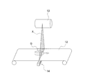
- FIG. 1 is an external perspective view of the X-ray inspection apparatus 10 according to an embodiment of the present invention.
- the X-ray inspection apparatus 10 is one of the apparatuses incorporated in the production line (see FIG. 6) of goods G such as food and performing quality inspection of goods G, and is continuously transported. It is an apparatus which judges the quality of goods G by irradiating an X ray to goods G.
- the commodity G which is the inspection object is conveyed to the X-ray inspection apparatus 10 by the front stage conveyor 60 (see FIG. 6).
- the commodity G is classified into a non-defective product or a defective product in the X-ray inspection apparatus 10.
- the inspection result in the X-ray inspection apparatus 10 is sent to a distribution mechanism 70 disposed on the downstream side of the X-ray inspection apparatus 10.
- the distribution mechanism 70 (see FIG. 6) sends the product G determined to be non-defective in the X-ray inspection apparatus 10 to the conveyor 80 for discharging a normal product, and the product determined to be defective in the X-ray inspection apparatus 10 G is distributed to the defective discharge direction 91 and the defective discharge direction 92.
- FIG. 2 is an internal configuration diagram of a shield box of the X-ray inspection apparatus. 1 and 2, the X-ray inspection apparatus 10 includes a shield box 11, a conveyor 12, an X-ray irradiator 13, an X-ray line sensor 14, and a monitor 30 with a touch panel function (see FIG. 1). And a control computer 20 (see FIG. 4).
- Openings 11 a for carrying the product G in and out of the shield box 11 are formed on both side surfaces of the shield box 11.
- the opening 11 a is closed by a shielding Norren (not shown) in order to prevent leakage of X-rays to the outside of the shield box 11.
- This shielding Noren is molded from rubber containing lead, and is pushed out by the product G when the product G passes through the opening 11a.
- a conveyor 12 In the shield box 11, a conveyor 12, an X-ray irradiator 13, an X-ray line sensor 14, a control computer 20 and the like are accommodated. In addition to the monitor 30, an insertion port for a key, a power switch, and the like are disposed on the upper front of the shield box 11.
- the conveyor 12 conveys the goods G in the shield box 11, and as shown in FIG. 1, is disposed so as to pass through the openings 11a formed on both side surfaces of the shield box 11. And the conveyor 12 conveys the goods G mounted on the belt, rotating an endless belt with the drive roller driven by the conveyor motor 12a (refer FIG. 4).
- the conveyance speed by the conveyor 12 is finely controlled by the inverter control of the conveyor motor 12 a by the control computer 20 so as to be the set speed input by the operator.
- an encoder 12 b (see FIG. 4) that detects the conveyance speed of the conveyor 12 and sends it to the control computer 20 is attached to the conveyor motor 12 a.
- the X-ray irradiator 13 as a light irradiator is disposed above the conveyor 12 and irradiates X-rays to a fan-shaped irradiation range X toward the X-ray line sensor 14 below. .
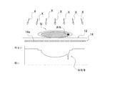
- FIG. 3 is a schematic view showing the principle of X-ray inspection.
- the X-ray line sensor 14 is disposed below the conveyor 12 and mainly comprises a large number of pixel sensors 14 a. These pixel sensors 14 a are horizontally arranged in a straight line in the direction orthogonal to the conveyance direction by the conveyor 12. Further, each pixel sensor 14a detects X-rays transmitted through the product G and the conveyor 12, and outputs an X-ray fluoroscopic image signal. The X-ray fluoroscopic image signal indicates the brightness (density) of the X-ray.
- Monitor 30 is a liquid crystal display of full dot display, and displays a screen prompting the operator to input inspection parameters and the like required for inspection.
- the monitor 30 also has a touch panel function, and receives an input of inspection parameters and the like from the operator.
- FIG. 4 is a block diagram of the control computer 20.
- a control computer 20 includes a CPU (central processing unit) 21, a ROM (read only memory) 22, a RAM (random access memory) 23, a HDD (hard disk) 25 and a drive 24 for inserting storage media and the like. Is mounted.
- CPU central processing unit
- ROM read only memory
- RAM random access memory
- HDD hard disk
- the CPU 21 executes various programs stored in the ROM 22 and the HDD 25. Inspection parameters and inspection results are stored and accumulated in the HDD 25. The inspection parameters can be set and changed by the input from the operator using the touch panel function of the monitor 30. The operator can set such data to be stored and stored not only in the HDD 25 but also in the storage medium inserted in the drive 24.
- control computer 20 controls a display of data on the monitor 30 (not shown), and a key input circuit (not shown) for taking in key input data inputted by the operator via the touch panel of the monitor 30. And a communication port (not shown) that enables connection to an external device such as a printer (not shown) or a network such as a LAN.
- the respective units (21 to 25) of the control computer 20 are mutually connected via a bus line such as an address bus or a data bus.
- the control computer 20 is connected to a conveyor motor 12a, an encoder 12b, a photoelectric sensor 15, an X-ray irradiator 13, an X-ray line sensor 14 and the like.
- the photoelectric sensor 15 is a synchronous sensor for detecting the timing at which the product G, which is a sample, passes through the fan-shaped X-ray irradiation range X (see FIG. 2). It consists of a light emitter and a light receiver.
- the HDD 25 of the control computer 20 stores an inspection program including an image generation module, an area specification module, a weight estimation module, a weight diagnosis module, a foreign matter inspection module, and a comprehensive diagnosis module.
- the CPU 21 of the control computer 20 reads and executes these program modules to operate as an image generation unit 21a, an area determination unit 21b, a foreign matter inspection unit 21c, and a comprehensive diagnosis unit 21d (see FIG. 4).
- the image generation unit 21 a generates an X-ray transmission image of the product G based on the X-ray fluoroscopic image signal output from the X-ray line sensor 14.
- the image generation unit 21a sets the X-ray fluoroscopic image signal output from each pixel sensor 14a of the X-ray line sensor 14 as the time interval is small when the product G passes the fan-shaped X-ray irradiation range X (see FIG. 2).
- the X-ray transmission image of the product G is generated based on the acquired X-ray fluoroscopic image signal acquired in The timing at which the commodity G passes the fan-shaped X-ray irradiation range X is determined by the signal from the photoelectric sensor 15.
- the image generation unit 21a copies the product G by connecting data of each fine time interval related to the brightness of the X-ray obtained from each pixel sensor 14a of the X-ray line sensor 14 in time series in a matrix. Generate a line-through image.
- the image generation unit 21a has a main function of generating an X-ray transmission image, but in addition to the main function, the image generation unit 21a has some functions necessary to specify the position of a foreign substance (see FIG. 5). ). These will be described in the section "(4) Operation for specifying foreign material position".
- Region discrimination unit 21b The area discrimination unit 21 b discriminates a product area from an X-ray transmission image that copies the product G generated by the image generation unit 21 a.
- the foreign substance inspection unit 21c detects a foreign substance included in the product G by performing binarization processing on the X-ray transmission image of the product G generated by the image generation unit 21a. More specifically, if there is a region that appears darker than a preset threshold on the X-ray transmission image P of the product G, it is determined that foreign matter is mixed in the product G, and the product G is Judge as abnormal.
- the comprehensive diagnosis unit 21d receives a signal indicating that no abnormality is detected from the foreign matter inspection unit 21c, the comprehensive diagnosis unit 21d diagnoses the product G as non-defective. Then, the comprehensive diagnosis unit 21 d sends the diagnosis result to the distribution mechanism 70.
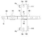
- FIG. 6 is a process configuration diagram of the X-ray inspection apparatus 10 before and after.
- the commodity G whose foreign matter has been detected by the X-ray inspection apparatus 10 (specifically, the foreign matter inspection unit 21c in FIG. 4) is excluded from the conveyor 80 by the sorting mechanism 70 and the foreign matter removal operation is performed. It will be.
- the foreign substance removal operation it is necessary to specify in advance the position of the foreign substance mixed in the product G, and the operation until the foreign substance position is specified will be described below.
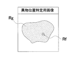
- FIG. 7A is an image view of the X-ray transmission image P0 of the commodity G in which a foreign substance is detected.
- a region Rg that appears dark is a silhouette of the product G.
- An area Rf that appears thin in the silhouette is determined to be a foreign object.
- the operator can display the original image on the screen as needed.
- FIG. 7B is an image view of the foreign material position specifying image.
- the Rf area which is the position of the foreign matter in the product G, is photographed dark by image processing. This foreign matter position specifying image can improve the visibility and improve the working efficiency.
- FIG. 8 is a flowchart of automatic generation control of the image for specifying foreign material position in FIG. 7B.
- the control computer 20 performs the following control via the image generation unit 21a.
- Step S1 First, in step S1, the control computer 20 determines the presence / absence of a command for generation of a foreign substance position specifying image, and when there is a command, the process proceeds to step S2. When there is no command, the presence / absence of a command for generation of a foreign substance position specification image Continue the judgment of.
- Step S2 the control computer 20 reads the target X-ray data in step S2, and proceeds to step S3.
- Step S3 the control computer 20 generates an X-ray transmission image P0 in step S3 and proceeds to step S4.
- Step S4 the control computer 20 performs image processing in step S4 to generate a foreign material position specifying image, and the control ends.
- the sorting mechanism 70 causes the sorting mechanism 70 to discharge the defective product in the defective discharge direction 91 and the defective discharge by the sorting mechanism 70 for the product G determined to be defective in the X-ray inspection apparatus 10. Sort in the direction 92.
- distribution mechanism 70 the system which distributes goods G by an arm is described as distribution mechanism 70, it is not limited to this, and the system which pushes out goods G with a pusher may be used.
- the defective discharge direction 91 side is connected to the first working unit 101, and the defective discharge direction 92 side is connected to the second working unit 102.
- a first display unit 111 is installed in the first working unit 101, and a second display unit 112 is installed in the second working unit 102.
- the first display unit 111 and the second display unit 112 are separate from the monitor 30 attached to the X-ray inspection apparatus 10 main body.
- a liquid crystal display is adopted as the first display unit 111 and the second display unit 112.
- the present invention is not limited to this, and any monitor capable of displaying an image may be used.
- the worker Pa who performs the foreign matter removing operation in the first operation unit 101 performs the foreign matter removing operation at a position facing the first display unit 111.
- a worker Pb performing a foreign matter removing operation in the second operation unit 102 performs the foreign matter removing operation at a position facing the second display unit 112.
- the first operation unit 101 an image for specifying the foreign matter position of the product Ga sent from the main body of the X-ray inspection apparatus 10 is displayed on the first display unit 111, and the worker Pa is an image for specifying the foreign matter position of the product Ga Check the position of foreign matter while looking at and remove.
- an image for specifying the foreign matter position of the product Gb sent from the main body of the X-ray inspection apparatus 10 is displayed on the second display unit 112, and the worker Pb is the foreign matter position of the product Gb. Check the position of the foreign substance while looking at the identification image and remove it.
- the image for specifying the foreign matter position of the commodity Ga, which is sorted to the first working unit 101, is automatically sorted to the first display unit 111, and the second The foreign substance position specifying image of the product Gb distributed to the work unit 102 is automatically distributed to the second display unit 112.
- the first display unit 111 and the second display unit 112 can divide the screen into two and simultaneously display a plurality of images. For example, if two articles G are distributed, images for specifying two foreign object positions are displayed.
- FIG. 9 is an image view of the display unit on which the images for specifying the foreign material position of the Nth product with foreign matter and the N + 1th product with foreign matter are simultaneously displayed.
- the left side in FIG. 9 front view is an image for specifying the foreign matter position of the N-th product inspected first.
- the first display unit 111 and the second display unit 112 divide and display them in time series, and the image for specifying the foreign matter position of the product G for which the removal operation is finished Can be sequentially sent in the same direction while sliding the image in one direction (right to left as viewed from the front in FIG. 9).
- FIG. 10 is an image diagram of the display unit on which the images for specifying the foreign material position of the (N to N + 4) foreign substance-containing products are simultaneously displayed.
- the first display unit 111 and the second display unit 112 divide the screen into four and display the images for specifying the foreign matter position of the four products G. It can correspond.
- the size of the screen is smaller, there is no problem because it is sufficient to know the rough place of the foreign matter.
- FIG. 11 is an image view of a display unit on which an image for specifying a foreign material position and an image obtained by inverting the image are displayed.
- the first display unit 111 and the second display unit 112 can invert the displayed image for specifying a foreign material position.
- the first display unit 111 or the second display unit 112 displays both the foreign material position specifying image and the inverted image obtained by inverting the image, it is possible to display only the inverted image.
- the surface facing upward when flowing on the conveyor may be turned downward during the foreign matter removing operation to remove the foreign matter.
- the reverse control of the foreign material position specifying image can be turned on / off. Further, the operator can perform the reverse operation of the foreign substance position specifying image.
- the X-ray inspection apparatus 10 fixes the distributed foreign substance position specifying image during the foreign substance removing operation. That is, the display is not switched even if there is a next image for specifying the position of foreign matter. This improves the efficiency of the foreign matter removal operation.
- the foreign substance position specifying image may be continuously displayed for a predetermined time, or may be manually switched when the work is completed.
- Modification (7-1) Although the above embodiment has been described on the assumption that there are two distribution destinations, there may be a case where only one distribution destination is provided due to the convenience of the production line. In such a case, by arranging workers Pa and Pb on a work table for removing foreign matter, one distribution destination constitutes a plurality of work units, and one screen is divided into two. A plurality of display units may be configured.
- the display unit may display the foreign material position specifying image only on the working unit to which the product G requiring the foreign matter removing operation is distributed.
- the worker Pa performs the foreign object position while looking at the foreign object position specifying image of the product Ga (or Gb) displayed on the first display unit 111 (or the second display unit 112).
- a configuration may be adopted in which the ink is ejected to the foreign matter position of the product.
- an inkjet having a plurality of (for example, eight) jet openings is disposed above the path through which the commodity G passes through the X-ray inspection apparatus 10. That is, at the same time as the foreign matter inspection unit 21c detects a foreign matter contained in the product G, the ink is ejected onto the product surface at the position where the foreign matter is present. This makes it possible to more quickly identify the foreign matter position.
- the foreign matter detected by the X-ray inspection apparatus 10 includes a foreign matter which the operator can not easily find even if it is represented in the foreign matter position specifying image, and it may take time for the foreign matter removing operation. In such a case, if the next product with foreign matter is discharged and flows, if it is known in advance whether it is a foreign material that is easy to remove, it is more efficient to remove foreign matter from the product first. is there.
- the foreign substance inspection unit 21c detects foreign substances contained in the product G and at the same time determines whether the size of the foreign substance is larger than the preset size, and the size of the foreign substance is larger than the preset size When it is determined, a notification sound may be issued to prompt the worker to remove foreign matter of the product G first.
- the comparative evaluation may be performed based on whether the foreign matter is larger than the foreign matter of the product determined to have foreign matter previously. Also, when the product G is chicken and it is clearly understood that it is “bone”, it is judged that “bones which are dangerous to eat” and “bones like cartilage” are distinguished as “bones which are dangerous to eat” You may make a notification sound.
- FIG. 12A is an image view of the X-ray transmission image P0 of the commodity G in which foreign matter is detected.
- a region Rg that appears dark is a silhouette of the product G.
- An area Rf that appears thin in the silhouette is determined to be a foreign object.
- the operator can display the original image on the screen as needed.
- FIG. 12B is an image diagram of the foreign substance extraction image P1.
- the foreign substance extraction image P1 is an image obtained by extracting a region Rf determined as a foreign substance of the X-ray transmission image P0.
- the image generation unit 21a has a function of generating a foreign matter extraction image P1 (hereinafter referred to as a first function).
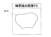
- FIG. 12C is an image diagram of the contour extraction image P2.
- the contour extraction image P2 is an image obtained by extracting only the contour of the region Rg of the X-ray transmission image P0.
- the image generation unit 21a has a function of generating a contour extraction image P2 (hereinafter referred to as a second function).
- the image generation unit 21a normalizes the contour in the edge-processed image by the expansion / contraction processing, and an edge processing function that emphasizes a spatial change of luminance in the X-ray transmission image P0 as the contour in order to specify the contour. It further has a standardization function.
- FIG. 12D is an image view of the foreign material position specifying image P3.
- the foreign substance position specifying image P3 is an image in which the contour extraction image P2 is combined with the foreign substance extraction image P1 and the position of the foreign substance in the product G is specified.
- the image generation unit 21a has a function (hereinafter, referred to as a third function) of generating the foreign substance position specifying image P3.
- the monitor 30 may be provided with an adjustment unit 33 that adjusts the inspection sensitivity while displaying the foreign substance position specifying image P3 on the monitor 30.
- the image generation unit 21a further has a coloring function of coloring the outlines on the outline extraction image P2 and the foreign substance position specifying image P3 or coloring the inside of the outlines. It is possible to color or to color the inside of the outline, to improve the visibility and to improve the working efficiency.
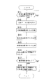
- FIG. 13 is a flowchart of automatic generation control of the foreign substance position specifying image P3 in another embodiment.
- the control computer 20 performs the following control via the image generation unit 21a.
- Step S11 First, in step S11, the control computer 20 determines the presence / absence of an instruction to generate the foreign object position specifying image P3. When there is an instruction, the process proceeds to step S12, and when there is no instruction, the instruction to generate the foreign object position specifying image P3. Continue to determine the presence or absence of
- Step S12 the control computer 20 reads the target X-ray data in step S12, and proceeds to step S13.
- Step S13 the control computer 20 generates an X-ray transmission image P0 in step S13, and proceeds to step S14.
- Step S14 Next, the control computer 20 generates a foreign matter extraction image P1 in step S14, and proceeds to step S15.
- Step S15 Next, the control computer 20 creates a contour extraction image P2 in step S15, and proceeds to step S16.
- Step S16 the control computer 20 combines the contour extraction image P2 with the foreign material extraction image P1 to generate a foreign material position specifying image P3.
- step S17 the control computer 20 determines the presence or absence of an instruction to color the contour of the foreign substance position specifying image P3. If there is an instruction, the process proceeds to step S18. If there is no instruction, the control is ended.
- step S18 the control computer 20 colors the outline of the article in the foreign substance position specifying image P3 and ends the control.
- FIG. 14 is a block diagram of a control computer according to another embodiment.
- the CPU 21 of the control computer 20 is not limited to the weight estimation unit 21e and the weight other than the image generation unit 21a, the area determination unit 21b, the foreign matter inspection unit 21c and the comprehensive diagnosis unit 21d (see FIG. 4) described in the above embodiment. It has a diagnosis unit 21f.
- Weight estimation unit 21e estimates the weight of the product G by performing image processing on the product region determined by the region determination unit 21b.
- the weight estimation processing is performed on the X-ray transmission image P using the property that the thicker the material in the irradiation direction of the X-ray is, the darker it is, and it is performed based on the following principle.
- the brightness I of a pixel for copying a substance of thickness t on the X-ray transmission image P is represented by the following formula (1), where the brightness of the pixel contained in the area where no substance is present is I 0 .
- Equation (1) is solved for the thickness t of a substance, Equation (2) below is obtained.
- the weight of the micro area of the content is proportional to the thickness of the micro area. Therefore, the weight m of the minute portion of the contents copied by the pixel of brightness I is approximately calculated by the following equation (3) using an appropriate constant ⁇ .
- the weight estimation unit 21 e estimates the weight of the entire product G by calculating and adding weights m corresponding to all the pixels constituting the product G.
- Weight diagnostic unit 21f The weight diagnostic unit 21 f checks whether the weight of the content of the product G is within a predetermined range. Then, when the weight is within the range, the product G is diagnosed as normal, and when the weight is not within the range, the product G is diagnosed as weight abnormality.
- the processing by the weight diagnosis unit 21 f is performed in parallel behind the processing by the weight estimation unit 21 e.
- the present invention determines the presence or absence of a defect in the article based on a light emitting unit that emits light to the article, an image generation unit that generates an image of the article based on the light, and an image generated by the image generation unit. If it is an inspection apparatus provided with the judgment part which makes it, it is useful also to inspection apparatuses other than X-ray inspection apparatus.
Abstract
L'invention concerne un dispositif d'inspection permettant à un opérateur de réaliser efficacement une opération de retrait de corps étranger. Un dispositif d'inspection par rayons X (10) est configuré de sorte que, même lorsqu'il existe une première partie d'opération (101) et une deuxième partie d'opération (102) comme pluralité de parties d'opération, des images d'identification d'emplacement de corps étranger (P3) de produits (Ga, Gb) attribuées respectivement à la première partie d'opération (101) et à la deuxième partie d'opération (102) sont affichées et des opérateurs (Pa, Pb) peuvent identifier des emplacements de corps étranger tout en regardant les images d'identification d'emplacement de corps étranger (P3) dans la première partie d'opération (101) et la deuxième partie d'opération (102) attribuées respectivement. Ainsi, une opération de retrait de corps étranger est accélérée.
Applications Claiming Priority (2)
| Application Number | Priority Date | Filing Date | Title |
|---|---|---|---|
| JP2017-241905 | 2017-12-18 | ||
| JP2017241905A JP7239960B2 (ja) | 2017-12-18 | 2017-12-18 | 検査装置 |
Publications (1)
| Publication Number | Publication Date |
|---|---|
| WO2019123802A1 true WO2019123802A1 (fr) | 2019-06-27 |
Family
ID=66994559
Family Applications (1)
| Application Number | Title | Priority Date | Filing Date |
|---|---|---|---|
| PCT/JP2018/038614 WO2019123802A1 (fr) | 2017-12-18 | 2018-10-17 | Dispositif d'inspection |
Country Status (2)
| Country | Link |
|---|---|
| JP (1) | JP7239960B2 (fr) |
| WO (1) | WO2019123802A1 (fr) |
Families Citing this family (1)
| Publication number | Priority date | Publication date | Assignee | Title |
|---|---|---|---|---|
| JP2021025874A (ja) * | 2019-08-05 | 2021-02-22 | 株式会社イシダ | 検査装置 |
Citations (3)
| Publication number | Priority date | Publication date | Assignee | Title |
|---|---|---|---|---|
| JP2011089965A (ja) * | 2009-10-26 | 2011-05-06 | Ishida Co Ltd | 物品検査装置 |
| WO2014079448A1 (fr) * | 2012-11-22 | 2014-05-30 | Attec Danmark A/S | Procédé et moyen de contrôle et d'élimination de matières étrangères dans des produits alimentaires |
| JP2017138193A (ja) * | 2016-02-03 | 2017-08-10 | アンリツインフィビス株式会社 | 物品検査装置 |
Family Cites Families (6)
| Publication number | Priority date | Publication date | Assignee | Title |
|---|---|---|---|---|
| JP2002162705A (ja) * | 2000-11-24 | 2002-06-07 | Konica Corp | 位相コントラスト放射線画像処理装置 |
| JP4429635B2 (ja) * | 2003-06-04 | 2010-03-10 | 株式会社日立メディコ | 医用画像診断装置とその操作情報表示方法 |
| JP2013088165A (ja) * | 2011-10-14 | 2013-05-13 | Ishida Co Ltd | X線検査装置 |
| JP6022860B2 (ja) * | 2012-08-31 | 2016-11-09 | 株式会社イシダ | 物品検査装置及び物品検査方法 |
| JP6747771B2 (ja) * | 2015-01-26 | 2020-08-26 | コニカミノルタ株式会社 | 画像表示装置及び画像表示方法 |
| JP6200562B2 (ja) * | 2016-08-25 | 2017-09-20 | 富士フイルムRiファーマ株式会社 | 画像処理装置、方法及びコンピュータプログラム |
-
2017
- 2017-12-18 JP JP2017241905A patent/JP7239960B2/ja active Active
-
2018
- 2018-10-17 WO PCT/JP2018/038614 patent/WO2019123802A1/fr active Application Filing
Patent Citations (3)
| Publication number | Priority date | Publication date | Assignee | Title |
|---|---|---|---|---|
| JP2011089965A (ja) * | 2009-10-26 | 2011-05-06 | Ishida Co Ltd | 物品検査装置 |
| WO2014079448A1 (fr) * | 2012-11-22 | 2014-05-30 | Attec Danmark A/S | Procédé et moyen de contrôle et d'élimination de matières étrangères dans des produits alimentaires |
| JP2017138193A (ja) * | 2016-02-03 | 2017-08-10 | アンリツインフィビス株式会社 | 物品検査装置 |
Also Published As
| Publication number | Publication date |
|---|---|
| JP7239960B2 (ja) | 2023-03-15 |
| JP2019107605A (ja) | 2019-07-04 |
Similar Documents
| Publication | Publication Date | Title |
|---|---|---|
| CN101750033A (zh) | X射线检查装置 | |
| WO2019159440A1 (fr) | Dispositif d'inspection | |
| US7477726B2 (en) | X-ray inspection apparatus | |
| EP2163886A1 (fr) | Dispositif d'inspection à rayons x et système de fabrication | |
| KR20200097344A (ko) | 검사 장치 | |
| JP3828781B2 (ja) | X線異物検出装置 | |
| JP5864404B2 (ja) | X線検査装置 | |
| WO2019123802A1 (fr) | Dispositif d'inspection | |
| JP7219504B2 (ja) | 擬似不良品を用いて動作確認される検査装置 | |
| WO2021193733A1 (fr) | Dispositif de génération de données d'apprentissage, dispositif d'inspection et programme | |
| JP2005003480A (ja) | X線検査装置 | |
| JP2002098653A (ja) | X線検査装置 | |
| JP2019107605A5 (fr) | ||
| JP2015137858A (ja) | 検査装置 | |
| WO2017159855A1 (fr) | Dispositif d'inspection à rayons x | |
| JP2009168590A (ja) | X線検査装置 | |
| JP2007322344A (ja) | X線検査装置 | |
| EP3800468A1 (fr) | Dispositif d'inspection | |
| JP2005031069A (ja) | X線検査装置 | |
| JP2009080031A (ja) | X線検査装置 | |
| JP2015155831A (ja) | 包装体検査装置 | |
| WO2017159856A1 (fr) | Appareil d'inspection par rayons x | |
| JP3511505B2 (ja) | X線検査装置 | |
| JP4005117B2 (ja) | X線検査装置 | |
| JP6941851B2 (ja) | 質量推定装置 |
Legal Events
| Date | Code | Title | Description |
|---|---|---|---|
| 121 | Ep: the epo has been informed by wipo that ep was designated in this application |
Ref document number: 18892841 Country of ref document: EP Kind code of ref document: A1 |
|
| NENP | Non-entry into the national phase |
Ref country code: DE |
|
| 122 | Ep: pct application non-entry in european phase |
Ref document number: 18892841 Country of ref document: EP Kind code of ref document: A1 |