WO2019123802A1 - Inspection device - Google Patents
Inspection device Download PDFInfo
- Publication number
- WO2019123802A1 WO2019123802A1 PCT/JP2018/038614 JP2018038614W WO2019123802A1 WO 2019123802 A1 WO2019123802 A1 WO 2019123802A1 JP 2018038614 W JP2018038614 W JP 2018038614W WO 2019123802 A1 WO2019123802 A1 WO 2019123802A1
- Authority
- WO
- WIPO (PCT)
- Prior art keywords
- image
- unit
- inspection apparatus
- foreign matter
- product
- Prior art date
Links
Images


Classifications
-
- B—PERFORMING OPERATIONS; TRANSPORTING
- B07—SEPARATING SOLIDS FROM SOLIDS; SORTING
- B07C—POSTAL SORTING; SORTING INDIVIDUAL ARTICLES, OR BULK MATERIAL FIT TO BE SORTED PIECE-MEAL, e.g. BY PICKING
- B07C5/00—Sorting according to a characteristic or feature of the articles or material being sorted, e.g. by control effected by devices which detect or measure such characteristic or feature; Sorting by manually actuated devices, e.g. switches
- B07C5/34—Sorting according to other particular properties
- B07C5/346—Sorting according to other particular properties according to radioactive properties
-
- G—PHYSICS
- G01—MEASURING; TESTING
- G01N—INVESTIGATING OR ANALYSING MATERIALS BY DETERMINING THEIR CHEMICAL OR PHYSICAL PROPERTIES
- G01N23/00—Investigating or analysing materials by the use of wave or particle radiation, e.g. X-rays or neutrons, not covered by groups G01N3/00 – G01N17/00, G01N21/00 or G01N22/00
- G01N23/02—Investigating or analysing materials by the use of wave or particle radiation, e.g. X-rays or neutrons, not covered by groups G01N3/00 – G01N17/00, G01N21/00 or G01N22/00 by transmitting the radiation through the material
- G01N23/04—Investigating or analysing materials by the use of wave or particle radiation, e.g. X-rays or neutrons, not covered by groups G01N3/00 – G01N17/00, G01N21/00 or G01N22/00 by transmitting the radiation through the material and forming images of the material
-
- G—PHYSICS
- G01—MEASURING; TESTING
- G01N—INVESTIGATING OR ANALYSING MATERIALS BY DETERMINING THEIR CHEMICAL OR PHYSICAL PROPERTIES
- G01N23/00—Investigating or analysing materials by the use of wave or particle radiation, e.g. X-rays or neutrons, not covered by groups G01N3/00 – G01N17/00, G01N21/00 or G01N22/00
- G01N23/02—Investigating or analysing materials by the use of wave or particle radiation, e.g. X-rays or neutrons, not covered by groups G01N3/00 – G01N17/00, G01N21/00 or G01N22/00 by transmitting the radiation through the material
- G01N23/06—Investigating or analysing materials by the use of wave or particle radiation, e.g. X-rays or neutrons, not covered by groups G01N3/00 – G01N17/00, G01N21/00 or G01N22/00 by transmitting the radiation through the material and measuring the absorption
- G01N23/083—Investigating or analysing materials by the use of wave or particle radiation, e.g. X-rays or neutrons, not covered by groups G01N3/00 – G01N17/00, G01N21/00 or G01N22/00 by transmitting the radiation through the material and measuring the absorption the radiation being X-rays
-
- G—PHYSICS
- G01—MEASURING; TESTING
- G01N—INVESTIGATING OR ANALYSING MATERIALS BY DETERMINING THEIR CHEMICAL OR PHYSICAL PROPERTIES
- G01N23/00—Investigating or analysing materials by the use of wave or particle radiation, e.g. X-rays or neutrons, not covered by groups G01N3/00 – G01N17/00, G01N21/00 or G01N22/00
- G01N23/02—Investigating or analysing materials by the use of wave or particle radiation, e.g. X-rays or neutrons, not covered by groups G01N3/00 – G01N17/00, G01N21/00 or G01N22/00 by transmitting the radiation through the material
- G01N23/06—Investigating or analysing materials by the use of wave or particle radiation, e.g. X-rays or neutrons, not covered by groups G01N3/00 – G01N17/00, G01N21/00 or G01N22/00 by transmitting the radiation through the material and measuring the absorption
- G01N23/12—Investigating or analysing materials by the use of wave or particle radiation, e.g. X-rays or neutrons, not covered by groups G01N3/00 – G01N17/00, G01N21/00 or G01N22/00 by transmitting the radiation through the material and measuring the absorption the material being a flowing fluid or a flowing granular solid
-
- G—PHYSICS
- G01—MEASURING; TESTING
- G01N—INVESTIGATING OR ANALYSING MATERIALS BY DETERMINING THEIR CHEMICAL OR PHYSICAL PROPERTIES
- G01N23/00—Investigating or analysing materials by the use of wave or particle radiation, e.g. X-rays or neutrons, not covered by groups G01N3/00 – G01N17/00, G01N21/00 or G01N22/00
- G01N23/02—Investigating or analysing materials by the use of wave or particle radiation, e.g. X-rays or neutrons, not covered by groups G01N3/00 – G01N17/00, G01N21/00 or G01N22/00 by transmitting the radiation through the material
- G01N23/06—Investigating or analysing materials by the use of wave or particle radiation, e.g. X-rays or neutrons, not covered by groups G01N3/00 – G01N17/00, G01N21/00 or G01N22/00 by transmitting the radiation through the material and measuring the absorption
- G01N23/18—Investigating the presence of flaws defects or foreign matter
Landscapes
- Health & Medical Sciences (AREA)
- General Health & Medical Sciences (AREA)
- Life Sciences & Earth Sciences (AREA)
- Chemical & Material Sciences (AREA)
- Analytical Chemistry (AREA)
- Biochemistry (AREA)
- Physics & Mathematics (AREA)
- General Physics & Mathematics (AREA)
- Immunology (AREA)
- Pathology (AREA)
- Toxicology (AREA)
- Analysing Materials By The Use Of Radiation (AREA)
- Sorting Of Articles (AREA)
Abstract
The present invention addresses the problem of providing an inspection device that enables an operator to efficiently carry out foreign object removal operation. An X-ray inspection device (10) is configured such that even when there are a first operation portion (101) and a second operation portion (102) as a plurality of operation portions, foreign object position identification images (P3) of products (Ga, Gb) respectively allocated to the first operation portion (101) and the second operation portion (102) are displayed, and operators (Pa, Pb) can identify foreign object positions while watching necessary ones of the foreign object position identification images (P3) in the first operation portion (101) and the second operation portion (102) respectively allocated. Thus, foreign object removal operation is expedited.
Description
本発明は、検査装置に関する。
The present invention relates to an inspection apparatus.
従来、物品への異物混入の有無を判定する手段として画像を用いた検査装置が利用されている。例えば、特許文献1(特願2016-55555号)に記載のX線検査装置は、異物位置特定用画像を生成し、作業員が商品における異物の位置を容易に特定することができるようにしている。
2. Description of the Related Art Conventionally, an inspection apparatus using an image has been used as means for determining the presence or absence of foreign matter in an article. For example, the X-ray inspection apparatus described in Patent Document 1 (Japanese Patent Application No. 2016-55555) generates an image for specifying a foreign matter position so that the worker can easily specify the position of the foreign matter in the product. There is.
一方、検査ラインでは、異物有りと判定された商品を振り分けて、作業員が異物の除去作業を行うが、除去作業に時間がかかり過ぎると、異物混入商品が滞留し生産効率が低下する。
On the other hand, in the inspection line, the worker performs the removal operation of the foreign material by distributing the products determined as the presence of the foreign material, but if the removal operation takes too much time, the foreign matter mixed product stays and the production efficiency decreases.
本発明の課題は、作業員による異物の除去作業を効率的に行うことができる検査装置を提供することにある。
An object of the present invention is to provide an inspection apparatus capable of efficiently removing foreign matter by a worker.
本発明の第1観点に係る検査装置は、物品に光を照射する光照射部と、光に基づいて物品の画像を生成する画像生成部と、画像生成部により生成された画像に基づいて物品における不良の有無を判断する判断部とを備える検査装置であって、作業部と、振分機構と、表示部とをさらに備えている。作業部では、作業員が異物の除去作業を行う。振分機構は、判断部で不良と判断された物品である作業対象物を作業部に振り分ける。表示部は、作業対象物が振り分けられた作業部において、作業員が視認可能に、当該作業対象物の画像を表示させる。
An inspection apparatus according to a first aspect of the present invention is an article based on an image generated by a light emitting unit that emits light to an article, an image generation unit that generates an image of the article based on the light, and an image generated by the image generation unit. The inspection apparatus includes a determination unit that determines the presence or absence of a defect in step b), and further includes a working unit, a distribution mechanism, and a display unit. In the working unit, a worker performs the removal operation of foreign matter. The distribution mechanism distributes the work object, which is an article determined to be defective by the determination unit, to the operation unit. The display unit displays an image of the work target in a work unit to which the work target is distributed in such a manner that the worker can visually recognize the work.
この検査装置では、作業部に作業対象物の検査結果画像が表示されることによって、作業員による異物の除去作業がはかどる。
In this inspection apparatus, when the inspection result image of the work object is displayed on the working unit, the work of removing foreign matter by the operator is accelerated.
本発明の第2観点に係る検査装置は、第1観点に係る検査装置であって、表示部が作業部ごとに設けられている。
An inspection apparatus according to a second aspect of the present invention is the inspection apparatus according to the first aspect, and a display unit is provided for each work unit.
この検査装置では、複数の作業部が存在しても、作業部ごとに振り分けられた作業対象物の検査結果画像が表示されるので、作業員は割り当てられた作業部で必要な検査結果画像を見ることができる。
In this inspection apparatus, even if there are a plurality of work units, the inspection result image of the work object distributed to each work unit is displayed, so the worker can check the necessary inspection result images in the assigned work units. I can see it.
本発明の第3観点に係る検査装置は、第1観点に係る検査装置であって、表示部が、複数の作業部に共通の1つの表示手段である。
The inspection apparatus according to the third aspect of the present invention is the inspection apparatus according to the first aspect, and the display unit is one display means common to a plurality of working units.
この検査装置では、表示部を1つに集約することによって、除去作業が必要な作業対象物が振り分けられた作業部に対してのみ検査結果画面を表示すればよい。また、複数の作業部に対して検査結果画像を表示する必要があるときは、表示部に画面を必要な数だけ作成すれば足りる。したがって、表示部の過剰設置が防止される。
In this inspection apparatus, by integrating the display units into one, the inspection result screen may be displayed only for the work unit to which the work object requiring the removal work is distributed. In addition, when it is necessary to display examination result images to a plurality of working units, it is sufficient to create as many screens as necessary on the display unit. Therefore, excessive installation of the display unit is prevented.
本発明の第4観点に係る検査装置は、第1観点から第3観点のいずれか1つに係る検査装置であって、作業対象の画像を固定して表示する。
An inspection apparatus according to a fourth aspect of the present invention is the inspection apparatus according to any one of the first to third aspects, and fixes and displays an image of a work target.
この検査装置では、振り分けられたNG画像を作業の間固定する(次のNG画像があっても、表示を切り替えない)ことで、異物除去作業の効率が向上する。
In this inspection apparatus, the efficiency of the foreign matter removing operation is improved by fixing the distributed NG image during the operation (without switching the display even if there is the next NG image).
NG画像は所定の時間だけ表示させ続けるか、或いは、作業が完了した場合に手動で切替える。
The NG image is kept displayed for a predetermined time or manually switched when the work is completed.
本発明の第5観点に係る検査装置は、第1観点から第4観点のいずれか1つに係る検査装置であって、表示部が、1つの作業部に振り分けられた複数の作業対象物の画像を分割して表示する。
An inspection apparatus according to a fifth aspect of the present invention is the inspection apparatus according to any one of the first to fourth aspects, wherein the display unit is a plurality of work objects distributed to one work unit. Divide and display the image.
この検査装置では、1つの作業部に複数の作業対象物が振り分けられた場合でも、作業対象物ごとの検査結果画像を同時に表示することができるので、作業員はどの作業対象物に対してどの検査結果画像をみるべきかを把握し、作業対象物から異物の除去を効率良く行うことができる。
In this inspection apparatus, even when a plurality of work objects are distributed to one work unit, the inspection result image for each work object can be simultaneously displayed. It is possible to grasp whether the inspection result image should be viewed and efficiently remove foreign matter from the work object.
本発明の第6観点に係る検査装置は、第1観点から第5観点のいずれか1つに係る検査装置であって、表示部が、反転させた作業対象物の画像を表示する。
The inspection apparatus according to a sixth aspect of the present invention is the inspection apparatus according to any one of the first aspect to the fifth aspect, wherein the display unit displays the image of the reversed work object.
この検査装置では、例えば、鶏肉のような商品は皮を上にして搬送されるが、作業部での異物除去の際には皮を下にしているので、作業対象物の異物の位置は、検査結果画像を反転させたときの位置と一致する。それゆえ、検査結果画像を反転させることによって、作業対象物の異物の位置と、画像に表示される異物の位置とが一致し、異物除去作業が容易になる。
In this inspection apparatus, for example, a product such as chicken is transported with the skin up, but the skin is down when removing foreign matter in the working unit, so the position of the foreign body of the work object is It matches the position when the inspection result image is inverted. Therefore, by inverting the inspection result image, the position of the foreign matter of the work object coincides with the position of the foreign matter displayed in the image, and the foreign matter removing operation becomes easy.
本発明の第7観点に係る検査装置は、第1観点から第6観点のいずれか1つに係る検査装置であって、光がX線である。
An inspection apparatus according to a seventh aspect of the present invention is the inspection apparatus according to any one of the first to sixth aspects, wherein the light is an X-ray.
本発明の第8観点に係る検査装置は、第1観点から第7観点のいずれか1つに係る検査装置であって、作業対象物は、作業部で異物除去を行うために異物の有無が検査された食品である。
An inspection apparatus according to an eighth aspect of the present invention is the inspection apparatus according to any one of the first aspect to the seventh aspect, and the work object has the presence or absence of a foreign substance for removing foreign substances in the working unit. It is a tested food.
本発明の第1観点に係る検査装置では、作業部に作業対象物の検査結果画像が表示されることによって、作業員による異物の除去作業がはかどる。
In the inspection apparatus according to the first aspect of the present invention, the inspection result image of the work object is displayed on the operation unit, thereby removing the foreign matter by the operator.
以下図面を参照しながら、本発明の実施形態について説明する。なお、以下の実施形態は、本発明の具体例であって、本発明の技術的範囲を限定するものではない。
Hereinafter, embodiments of the present invention will be described with reference to the drawings. The following embodiments are specific examples of the present invention and do not limit the technical scope of the present invention.
(1)X線検査装置10全体の構成
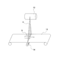
図1は、本発明の一実施形態に係るX線検査装置10の外観斜視図である。図1において、X線検査装置10は、食品等の商品Gの生産ライン(図6参照)に組み込まれて商品Gの品質検査を行う装置の1つであって、連続的に搬送されてくる商品Gに対してX線を照射することにより商品Gの良否判断を行う装置である。 (1) Configuration of EntireX-ray Inspection Apparatus 10 FIG. 1 is an external perspective view of the X-ray inspection apparatus 10 according to an embodiment of the present invention. In FIG. 1, the X-ray inspection apparatus 10 is one of the apparatuses incorporated in the production line (see FIG. 6) of goods G such as food and performing quality inspection of goods G, and is continuously transported. It is an apparatus which judges the quality of goods G by irradiating an X ray to goods G.
図1は、本発明の一実施形態に係るX線検査装置10の外観斜視図である。図1において、X線検査装置10は、食品等の商品Gの生産ライン(図6参照)に組み込まれて商品Gの品質検査を行う装置の1つであって、連続的に搬送されてくる商品Gに対してX線を照射することにより商品Gの良否判断を行う装置である。 (1) Configuration of Entire
検査対象物である商品Gは、前段コンベア60(図6参照)によってX線検査装置10のところまで運ばれてくる。商品Gは、X線検査装置10において良品または不良品に分類される。このX線検査装置10での検査結果は、X線検査装置10の下流側に配置されている振分機構70に送られる。
The commodity G which is the inspection object is conveyed to the X-ray inspection apparatus 10 by the front stage conveyor 60 (see FIG. 6). The commodity G is classified into a non-defective product or a defective product in the X-ray inspection apparatus 10. The inspection result in the X-ray inspection apparatus 10 is sent to a distribution mechanism 70 disposed on the downstream side of the X-ray inspection apparatus 10.
振分機構70(図6参照)は、X線検査装置10において良品と判断された商品Gを、正常品を排出するコンベア80へと送り、X線検査装置10において不良品と判断された商品Gを、不良排出方向91、不良排出方向92へと振り分ける。
The distribution mechanism 70 (see FIG. 6) sends the product G determined to be non-defective in the X-ray inspection apparatus 10 to the conveyor 80 for discharging a normal product, and the product determined to be defective in the X-ray inspection apparatus 10 G is distributed to the defective discharge direction 91 and the defective discharge direction 92.
(2)詳細構成
図2は、X線検査装置のシールドボックスの内部構成図である。図1及び図2において、X線検査装置10は、シールドボックス11と、コンベア12と、X線照射器13と、X線ラインセンサ14と、タッチパネル機能付きのモニタ30(図1参照)と、制御コンピュータ20(図4参照)とから構成されている。 (2) Detailed Configuration FIG. 2 is an internal configuration diagram of a shield box of the X-ray inspection apparatus. 1 and 2, theX-ray inspection apparatus 10 includes a shield box 11, a conveyor 12, an X-ray irradiator 13, an X-ray line sensor 14, and a monitor 30 with a touch panel function (see FIG. 1). And a control computer 20 (see FIG. 4).
図2は、X線検査装置のシールドボックスの内部構成図である。図1及び図2において、X線検査装置10は、シールドボックス11と、コンベア12と、X線照射器13と、X線ラインセンサ14と、タッチパネル機能付きのモニタ30(図1参照)と、制御コンピュータ20(図4参照)とから構成されている。 (2) Detailed Configuration FIG. 2 is an internal configuration diagram of a shield box of the X-ray inspection apparatus. 1 and 2, the
(2-1)シールドボックス11
シールドボックス11の両側面には、商品Gをシールドボックス11の内外に搬入出させるための開口11aが形成されている。開口11aは、シールドボックス11の外部へのX線の漏洩を防止するために、遮蔽ノレン(図示せず)により塞がれている。この遮蔽ノレンは、鉛を含むゴムから成形されており、商品Gが開口11aを通過する際に商品Gによって押しのけられるようになっている。 (2-1)Shield box 11
Openings 11 a for carrying the product G in and out of the shield box 11 are formed on both side surfaces of the shield box 11. The opening 11 a is closed by a shielding Norren (not shown) in order to prevent leakage of X-rays to the outside of the shield box 11. This shielding Noren is molded from rubber containing lead, and is pushed out by the product G when the product G passes through the opening 11a.
シールドボックス11の両側面には、商品Gをシールドボックス11の内外に搬入出させるための開口11aが形成されている。開口11aは、シールドボックス11の外部へのX線の漏洩を防止するために、遮蔽ノレン(図示せず)により塞がれている。この遮蔽ノレンは、鉛を含むゴムから成形されており、商品Gが開口11aを通過する際に商品Gによって押しのけられるようになっている。 (2-1)
そして、シールドボックス11内には、コンベア12、X線照射器13、X線ラインセンサ14、制御コンピュータ20等が収容されている。また、シールドボックス11の正面上部には、モニタ30の他、キーの差し込み口および電源スイッチ等が配置されている。
In the shield box 11, a conveyor 12, an X-ray irradiator 13, an X-ray line sensor 14, a control computer 20 and the like are accommodated. In addition to the monitor 30, an insertion port for a key, a power switch, and the like are disposed on the upper front of the shield box 11.
(2-2)コンベア12
コンベア12は、シールドボックス11内において商品Gを搬送するものであり、図1に示すように、シールドボックス11の両側面に形成された開口11aを貫通するように配置されている。そして、コンベア12は、コンベアモータ12a(図4参照)によって駆動される駆動ローラによって無端状のベルトを回転させながら、ベルト上に載置された商品Gを搬送する。 (2-2)Conveyor 12
Theconveyor 12 conveys the goods G in the shield box 11, and as shown in FIG. 1, is disposed so as to pass through the openings 11a formed on both side surfaces of the shield box 11. And the conveyor 12 conveys the goods G mounted on the belt, rotating an endless belt with the drive roller driven by the conveyor motor 12a (refer FIG. 4).
コンベア12は、シールドボックス11内において商品Gを搬送するものであり、図1に示すように、シールドボックス11の両側面に形成された開口11aを貫通するように配置されている。そして、コンベア12は、コンベアモータ12a(図4参照)によって駆動される駆動ローラによって無端状のベルトを回転させながら、ベルト上に載置された商品Gを搬送する。 (2-2)
The
コンベア12による搬送速度は、オペレータが入力した設定速度になるように、制御コンピュータ20によるコンベアモータ12aのインバータ制御によって細かく制御される。また、コンベアモータ12aには、コンベア12による搬送速度を検出して制御コンピュータ20に送るエンコーダ12b(図4参照)が装着されている。
The conveyance speed by the conveyor 12 is finely controlled by the inverter control of the conveyor motor 12 a by the control computer 20 so as to be the set speed input by the operator. In addition, an encoder 12 b (see FIG. 4) that detects the conveyance speed of the conveyor 12 and sends it to the control computer 20 is attached to the conveyor motor 12 a.
(2-3)X線照射器13
光照射部としてのX線照射器13は、図2に示すように、コンベア12の上方に配置されており、下方のX線ラインセンサ14に向けて扇状の照射範囲XにX線を照射する。 (2-3)X-ray irradiator 13
As shown in FIG. 2, theX-ray irradiator 13 as a light irradiator is disposed above the conveyor 12 and irradiates X-rays to a fan-shaped irradiation range X toward the X-ray line sensor 14 below. .
光照射部としてのX線照射器13は、図2に示すように、コンベア12の上方に配置されており、下方のX線ラインセンサ14に向けて扇状の照射範囲XにX線を照射する。 (2-3)
As shown in FIG. 2, the
(2-4)X線ラインセンサ14
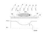
図3は、X線検査の原理を示す模式図である。図3において、X線ラインセンサ14は、コンベア12の下方に配置されており、主として多数の画素センサ14aから構成されている。これらの画素センサ14aは、コンベア12による搬送方向に直交する向きに一直線に水平配置されている。また、各画素センサ14aは、商品Gやコンベア12を透過したX線を検出し、X線透視像信号を出力する。X線透視像信号は、X線の明るさ(濃度)を示すものである。 (2-4)X-ray line sensor 14
FIG. 3 is a schematic view showing the principle of X-ray inspection. In FIG. 3, theX-ray line sensor 14 is disposed below the conveyor 12 and mainly comprises a large number of pixel sensors 14 a. These pixel sensors 14 a are horizontally arranged in a straight line in the direction orthogonal to the conveyance direction by the conveyor 12. Further, each pixel sensor 14a detects X-rays transmitted through the product G and the conveyor 12, and outputs an X-ray fluoroscopic image signal. The X-ray fluoroscopic image signal indicates the brightness (density) of the X-ray.
図3は、X線検査の原理を示す模式図である。図3において、X線ラインセンサ14は、コンベア12の下方に配置されており、主として多数の画素センサ14aから構成されている。これらの画素センサ14aは、コンベア12による搬送方向に直交する向きに一直線に水平配置されている。また、各画素センサ14aは、商品Gやコンベア12を透過したX線を検出し、X線透視像信号を出力する。X線透視像信号は、X線の明るさ(濃度)を示すものである。 (2-4)
FIG. 3 is a schematic view showing the principle of X-ray inspection. In FIG. 3, the
(2-5)モニタ30
モニタ30は、フルドット表示の液晶ディスプレイであり、検査時に必要となる検査パラメータ等の入力をオペレータに促す画面を表示する。また、モニタ30は、タッチパネル機能も有しており、オペレータからの検査パラメータ等の入力を受け付ける。 (2-5)Monitor 30
Themonitor 30 is a liquid crystal display of full dot display, and displays a screen prompting the operator to input inspection parameters and the like required for inspection. The monitor 30 also has a touch panel function, and receives an input of inspection parameters and the like from the operator.
モニタ30は、フルドット表示の液晶ディスプレイであり、検査時に必要となる検査パラメータ等の入力をオペレータに促す画面を表示する。また、モニタ30は、タッチパネル機能も有しており、オペレータからの検査パラメータ等の入力を受け付ける。 (2-5)
The
(2-6)制御コンピュータ20
図4は、制御コンピュータ20のブロック構成図である。図4において、制御コンピュータ20は、CPU(中央演算処理装置)21、ROM(リードオンリーメモリ)22、RAM(ランダムアクセスメモリ)23、HDD(ハードディスク)25および記憶メディア等を挿入するためのドライブ24を搭載している。 (2-6)Control computer 20
FIG. 4 is a block diagram of thecontrol computer 20. As shown in FIG. In FIG. 4, a control computer 20 includes a CPU (central processing unit) 21, a ROM (read only memory) 22, a RAM (random access memory) 23, a HDD (hard disk) 25 and a drive 24 for inserting storage media and the like. Is mounted.
図4は、制御コンピュータ20のブロック構成図である。図4において、制御コンピュータ20は、CPU(中央演算処理装置)21、ROM(リードオンリーメモリ)22、RAM(ランダムアクセスメモリ)23、HDD(ハードディスク)25および記憶メディア等を挿入するためのドライブ24を搭載している。 (2-6)
FIG. 4 is a block diagram of the
CPU21では、ROM22やHDD25に格納されている各種プログラムが実行される。HDD25には、検査パラメータや検査結果が保存蓄積される。検査パラメータについては、モニタ30のタッチパネル機能を使ったオペレータからの入力によって設定及び変更が可能である。オペレータは、これらのデータがHDD25だけでなくドライブ24に挿入された記憶メディアにも保存蓄積されるように設定することができる。
The CPU 21 executes various programs stored in the ROM 22 and the HDD 25. Inspection parameters and inspection results are stored and accumulated in the HDD 25. The inspection parameters can be set and changed by the input from the operator using the touch panel function of the monitor 30. The operator can set such data to be stored and stored not only in the HDD 25 but also in the storage medium inserted in the drive 24.
さらに、制御コンピュータ20は、モニタ30でのデータ表示を制御する表示制御回路(図示せず)、モニタ30のタッチパネルを介してオペレータにより入力されたキー入力データを取り込むキー入力回路(図示せず)、プリンタ(図示せず)等の外部機器やLAN等のネットワークとの接続を可能にする通信ポート(図示せず)なども備えている。
Furthermore, the control computer 20 controls a display of data on the monitor 30 (not shown), and a key input circuit (not shown) for taking in key input data inputted by the operator via the touch panel of the monitor 30. And a communication port (not shown) that enables connection to an external device such as a printer (not shown) or a network such as a LAN.
そして、制御コンピュータ20の各部(21~25)は、アドレスバスやデータバス等のバスラインを介して相互に接続されている。
The respective units (21 to 25) of the control computer 20 are mutually connected via a bus line such as an address bus or a data bus.
また、制御コンピュータ20は、コンベアモータ12a、エンコーダ12b、光電センサ15、X線照射器13、X線ラインセンサ14等に接続されている。光電センサ15は、検体である商品Gが扇状のX線の照射範囲X(図2参照)を通過するタイミングを検知するための同期センサであり、主として、コンベア12を挟んで配置される一対の投光器および受光器から構成されている。
The control computer 20 is connected to a conveyor motor 12a, an encoder 12b, a photoelectric sensor 15, an X-ray irradiator 13, an X-ray line sensor 14 and the like. The photoelectric sensor 15 is a synchronous sensor for detecting the timing at which the product G, which is a sample, passes through the fan-shaped X-ray irradiation range X (see FIG. 2). It consists of a light emitter and a light receiver.
(3)CPU21の構成
制御コンピュータ20のHDD25には、画像生成モジュール、領域特定モジュール、重量推定モジュール、重量診断モジュール、異物検査モジュールおよび総合診断モジュールを含む検査プログラムが格納されている。そして、制御コンピュータ20のCPU21は、これらのプログラムモジュールを読み出して実行することにより、画像生成部21a、領域判別部21b、異物検査部21cおよび総合診断部21d(図4参照)として動作する。 (3) Configuration ofCPU 21 The HDD 25 of the control computer 20 stores an inspection program including an image generation module, an area specification module, a weight estimation module, a weight diagnosis module, a foreign matter inspection module, and a comprehensive diagnosis module. The CPU 21 of the control computer 20 reads and executes these program modules to operate as an image generation unit 21a, an area determination unit 21b, a foreign matter inspection unit 21c, and a comprehensive diagnosis unit 21d (see FIG. 4).
制御コンピュータ20のHDD25には、画像生成モジュール、領域特定モジュール、重量推定モジュール、重量診断モジュール、異物検査モジュールおよび総合診断モジュールを含む検査プログラムが格納されている。そして、制御コンピュータ20のCPU21は、これらのプログラムモジュールを読み出して実行することにより、画像生成部21a、領域判別部21b、異物検査部21cおよび総合診断部21d(図4参照)として動作する。 (3) Configuration of
(3-1)画像生成部21a
画像生成部21aは、X線ラインセンサ14から出力されるX線透視像信号に基づいて、商品GのX線透過画像を生成する。画像生成部21aは、商品Gが扇状のX線の照射範囲X(図2参照)を通過するときにX線ラインセンサ14の各画素センサ14aから出力されるX線透視像信号を細かい時間間隔で取得し、取得したX線透視像信号に基づいて商品GのX線透過画像を生成する。なお、商品Gが扇状のX線の照射範囲Xを通過するタイミングは、光電センサ15からの信号により判断される。すなわち、画像生成部21aは、X線ラインセンサ14の各画素センサ14aから得られるX線の明るさに関する細かい時間間隔毎のデータをマトリクス状に時系列につなぎ合わせることにより、商品Gを写すX線透過画像を生成する。 (3-1)Image generation unit 21a
Theimage generation unit 21 a generates an X-ray transmission image of the product G based on the X-ray fluoroscopic image signal output from the X-ray line sensor 14. The image generation unit 21a sets the X-ray fluoroscopic image signal output from each pixel sensor 14a of the X-ray line sensor 14 as the time interval is small when the product G passes the fan-shaped X-ray irradiation range X (see FIG. 2). The X-ray transmission image of the product G is generated based on the acquired X-ray fluoroscopic image signal acquired in The timing at which the commodity G passes the fan-shaped X-ray irradiation range X is determined by the signal from the photoelectric sensor 15. That is, the image generation unit 21a copies the product G by connecting data of each fine time interval related to the brightness of the X-ray obtained from each pixel sensor 14a of the X-ray line sensor 14 in time series in a matrix. Generate a line-through image.
画像生成部21aは、X線ラインセンサ14から出力されるX線透視像信号に基づいて、商品GのX線透過画像を生成する。画像生成部21aは、商品Gが扇状のX線の照射範囲X(図2参照)を通過するときにX線ラインセンサ14の各画素センサ14aから出力されるX線透視像信号を細かい時間間隔で取得し、取得したX線透視像信号に基づいて商品GのX線透過画像を生成する。なお、商品Gが扇状のX線の照射範囲Xを通過するタイミングは、光電センサ15からの信号により判断される。すなわち、画像生成部21aは、X線ラインセンサ14の各画素センサ14aから得られるX線の明るさに関する細かい時間間隔毎のデータをマトリクス状に時系列につなぎ合わせることにより、商品Gを写すX線透過画像を生成する。 (3-1)
The
画像生成部21aは、X線透過画像を生成する機能が主機能であるが、この主機能のほかに、異物位置を特定するために必要ないくつかの機能を有している(図5参照)。これらについては「(4)異物位置の特定動作」の段で説明する。
The image generation unit 21a has a main function of generating an X-ray transmission image, but in addition to the main function, the image generation unit 21a has some functions necessary to specify the position of a foreign substance (see FIG. 5). ). These will be described in the section "(4) Operation for specifying foreign material position".
(3-2)領域判別部21b
領域判別部21bは、画像生成部21aにより生成された商品Gを写すX線透過画像から、商品領域を判別する。 (3-2)Region discrimination unit 21b
Thearea discrimination unit 21 b discriminates a product area from an X-ray transmission image that copies the product G generated by the image generation unit 21 a.
領域判別部21bは、画像生成部21aにより生成された商品Gを写すX線透過画像から、商品領域を判別する。 (3-2)
The
(3-3)異物検査部21c
異物検査部21cは、画像生成部21aにより生成された商品GのX線透過画像に対して2値化処理を施すことにより、商品Gに含まれる異物を検出する。より具体的には、商品GのX線透過画像P上に予め設定した閾値よりも暗く現れる領域が存在する場合には、その商品Gに異物が混入していると判断し、その商品Gを異常と判断する。 (3-3) Foreignmatter inspection unit 21c
The foreignsubstance inspection unit 21c detects a foreign substance included in the product G by performing binarization processing on the X-ray transmission image of the product G generated by the image generation unit 21a. More specifically, if there is a region that appears darker than a preset threshold on the X-ray transmission image P of the product G, it is determined that foreign matter is mixed in the product G, and the product G is Judge as abnormal.
異物検査部21cは、画像生成部21aにより生成された商品GのX線透過画像に対して2値化処理を施すことにより、商品Gに含まれる異物を検出する。より具体的には、商品GのX線透過画像P上に予め設定した閾値よりも暗く現れる領域が存在する場合には、その商品Gに異物が混入していると判断し、その商品Gを異常と判断する。 (3-3) Foreign
The foreign
(3-4)総合診断部21d
異物検査部21cは商品Gを異常と判断すると、直ちにその旨を示す信号を総合診断部21dに送る。総合診断部21dは、商品Gを不良品であると診断すると、直ちに異物検査部21cによる検査を終了させる。 (3-4)Comprehensive diagnosis unit 21d
When the foreignmatter inspection unit 21c determines that the product G is abnormal, the foreign matter inspection unit 21c immediately sends a signal indicating that to the comprehensive diagnostic unit 21d. When the comprehensive diagnostic unit 21 d diagnoses the product G as a defective product, the comprehensive diagnosis unit 21 d immediately terminates the inspection by the foreign matter inspection unit 21 c.
異物検査部21cは商品Gを異常と判断すると、直ちにその旨を示す信号を総合診断部21dに送る。総合診断部21dは、商品Gを不良品であると診断すると、直ちに異物検査部21cによる検査を終了させる。 (3-4)
When the foreign
また、総合診断部21dは、異物検査部21cから異常が検出されなかった旨を示す信号を受け取った場合には、商品Gを良品である診断する。そして、総合診断部21dは、診断結果を振分機構70へ送る。
Further, when the comprehensive diagnosis unit 21d receives a signal indicating that no abnormality is detected from the foreign matter inspection unit 21c, the comprehensive diagnosis unit 21d diagnoses the product G as non-defective. Then, the comprehensive diagnosis unit 21 d sends the diagnosis result to the distribution mechanism 70.
(4)異物位置の特定動作
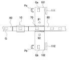
図6は、X線検査装置10の前後の工程構成図である。図6において、X線検査装置10(具体的には、図4の異物検査部21c)によって異物が検出された商品Gは、振分機構70によってコンベア80から除外され、異物の除去作業が行われる。異物の除去作業では、商品G内に混入した異物の位置を事前に特定する必要であり、異物位置が特定されるまでの動作を、以下に説明する。 (4) Operation for Identifying Foreign Material Position FIG. 6 is a process configuration diagram of theX-ray inspection apparatus 10 before and after. In FIG. 6, the commodity G whose foreign matter has been detected by the X-ray inspection apparatus 10 (specifically, the foreign matter inspection unit 21c in FIG. 4) is excluded from the conveyor 80 by the sorting mechanism 70 and the foreign matter removal operation is performed. It will be. In the foreign substance removal operation, it is necessary to specify in advance the position of the foreign substance mixed in the product G, and the operation until the foreign substance position is specified will be described below.
図6は、X線検査装置10の前後の工程構成図である。図6において、X線検査装置10(具体的には、図4の異物検査部21c)によって異物が検出された商品Gは、振分機構70によってコンベア80から除外され、異物の除去作業が行われる。異物の除去作業では、商品G内に混入した異物の位置を事前に特定する必要であり、異物位置が特定されるまでの動作を、以下に説明する。 (4) Operation for Identifying Foreign Material Position FIG. 6 is a process configuration diagram of the
(4-1)動作
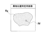
図7Aは、異物が検出された商品GのX線透過画像P0の画像図である。図7Aにおいて、濃く写る領域Rgは商品Gのシルエットである。そのシルエット中に薄く写る領域Rfが異物と判定されたものである。 (4-1) Operation FIG. 7A is an image view of the X-ray transmission image P0 of the commodity G in which a foreign substance is detected. In FIG. 7A, a region Rg that appears dark is a silhouette of the product G. An area Rf that appears thin in the silhouette is determined to be a foreign object.
図7Aは、異物が検出された商品GのX線透過画像P0の画像図である。図7Aにおいて、濃く写る領域Rgは商品Gのシルエットである。そのシルエット中に薄く写る領域Rfが異物と判定されたものである。 (4-1) Operation FIG. 7A is an image view of the X-ray transmission image P0 of the commodity G in which a foreign substance is detected. In FIG. 7A, a region Rg that appears dark is a silhouette of the product G. An area Rf that appears thin in the silhouette is determined to be a foreign object.
なお、異物検査部21cによって異物が検出された商品GのX線透過画像P0は、ROM22に格納されているので、オペレータは、随時、元画像を画面に表示することができる。
In addition, since the X-ray transmission image P0 of the product G in which the foreign matter is detected by the foreign matter inspection unit 21c is stored in the ROM 22, the operator can display the original image on the screen as needed.
図7Bは、異物位置特定用画像の画像図である。図7Bにおいて、商品Gにおける異物の位置であるRf領域が、画像処理により濃く写されている。この異物位置特定用画像によって、視認性を良くし、作業効率の向上を図ることができる。
FIG. 7B is an image view of the foreign material position specifying image. In FIG. 7B, the Rf area, which is the position of the foreign matter in the product G, is photographed dark by image processing. This foreign matter position specifying image can improve the visibility and improve the working efficiency.
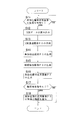
図8は、図7Bの異物位置特定用画像の自動生成制御のフローチャートである。図8において、制御コンピュータ20は画像生成部21aを介して以下の制御を行う。
FIG. 8 is a flowchart of automatic generation control of the image for specifying foreign material position in FIG. 7B. In FIG. 8, the control computer 20 performs the following control via the image generation unit 21a.
(ステップS1)
先ず、制御コンピュータ20は、ステップS1で異物位置特定用画像の生成指令の有無を判定し、指令があったときはステップS2に進み、指令がないときは異物位置特定用画像の生成指令の有無の判定を継続する。 (Step S1)
First, in step S1, thecontrol computer 20 determines the presence / absence of a command for generation of a foreign substance position specifying image, and when there is a command, the process proceeds to step S2. When there is no command, the presence / absence of a command for generation of a foreign substance position specification image Continue the judgment of.
先ず、制御コンピュータ20は、ステップS1で異物位置特定用画像の生成指令の有無を判定し、指令があったときはステップS2に進み、指令がないときは異物位置特定用画像の生成指令の有無の判定を継続する。 (Step S1)
First, in step S1, the
(ステップS2)
次に、制御コンピュータ20は、ステップS2で対象となるX線データを読み込み、ステップS3に進む。 (Step S2)
Next, thecontrol computer 20 reads the target X-ray data in step S2, and proceeds to step S3.
次に、制御コンピュータ20は、ステップS2で対象となるX線データを読み込み、ステップS3に進む。 (Step S2)
Next, the
(ステップS3)
次に、制御コンピュータ20は、ステップS3でX線透過画像P0を生成し、ステップS4に進む。 (Step S3)
Next, thecontrol computer 20 generates an X-ray transmission image P0 in step S3 and proceeds to step S4.
次に、制御コンピュータ20は、ステップS3でX線透過画像P0を生成し、ステップS4に進む。 (Step S3)
Next, the
(ステップS4)
そして、制御コンピュータ20は、ステップS4で画像処理をして異物位置特定用画像を生成し、制御を終了する。 (Step S4)
Then, thecontrol computer 20 performs image processing in step S4 to generate a foreign material position specifying image, and the control ends.
そして、制御コンピュータ20は、ステップS4で画像処理をして異物位置特定用画像を生成し、制御を終了する。 (Step S4)
Then, the
(5)異物除去工程
ここでは、図6を参照しながら異物位置特定用画像を用いた異物除去工程について説明する。図6に示すように、振分機構70は、X線検査装置10において不良品と判断された、すなわち、異物有りと判断された商品Gを、振分機構70によって不良排出方向91、不良排出方向92へと振り分ける。 (5) Foreign matter removing step Here, the foreign matter removing step using the foreign matter position specifying image will be described with reference to FIG. As shown in FIG. 6, thesorting mechanism 70 causes the sorting mechanism 70 to discharge the defective product in the defective discharge direction 91 and the defective discharge by the sorting mechanism 70 for the product G determined to be defective in the X-ray inspection apparatus 10. Sort in the direction 92.
ここでは、図6を参照しながら異物位置特定用画像を用いた異物除去工程について説明する。図6に示すように、振分機構70は、X線検査装置10において不良品と判断された、すなわち、異物有りと判断された商品Gを、振分機構70によって不良排出方向91、不良排出方向92へと振り分ける。 (5) Foreign matter removing step Here, the foreign matter removing step using the foreign matter position specifying image will be described with reference to FIG. As shown in FIG. 6, the
図6では、振分機構70として、商品Gをアームで振り分ける方式を記載しているが、これに限定されるものではなく、商品Gをプッシャーで押し出す方式であってもよい。
In FIG. 6, although the system which distributes goods G by an arm is described as distribution mechanism 70, it is not limited to this, and the system which pushes out goods G with a pusher may be used.
不良排出方向91側は第1作業部101と接続されており、不良排出方向92側は第2作業部102と接続されている。第1作業部101には第1表示部111が設置されており、第2作業部102には第2表示部112が設置されている。第1表示部111及び第2表示部112は、X線検査装置10本体に付いているモニタ30とは別個のものである。
The defective discharge direction 91 side is connected to the first working unit 101, and the defective discharge direction 92 side is connected to the second working unit 102. A first display unit 111 is installed in the first working unit 101, and a second display unit 112 is installed in the second working unit 102. The first display unit 111 and the second display unit 112 are separate from the monitor 30 attached to the X-ray inspection apparatus 10 main body.
本実施形態では、第1表示部111及び第2表示部112として液晶ディスプレイを採用しているが、これに限定されるものではなく、画像を表示できるモニタであれば良い。
In the present embodiment, a liquid crystal display is adopted as the first display unit 111 and the second display unit 112. However, the present invention is not limited to this, and any monitor capable of displaying an image may be used.
第1作業部101で異物除去作業を行う作業員Paは、第1表示部111と対峙する位置で異物除去作業を行う。同様に、第2作業部102で異物除去作業を行う作業員Pbは、第2表示部112と対峙する位置で異物除去作業を行う。
The worker Pa who performs the foreign matter removing operation in the first operation unit 101 performs the foreign matter removing operation at a position facing the first display unit 111. Similarly, a worker Pb performing a foreign matter removing operation in the second operation unit 102 performs the foreign matter removing operation at a position facing the second display unit 112.
異物有りと判断された商品Gaが不良排出方向91に排出され、第1作業部101で異物除去作業が行われている間に、他の商品Gbが異物有りと判定された場合には、当該商品Gbは不良排出方向92に排出され、第2作業部102で異物除去作業が行われる。
When the product Ga determined to have a foreign matter is discharged in the defect discharge direction 91 and the other product Gb is determined to have a foreign matter present while the first operation unit 101 is performing a foreign matter removing operation, The product Gb is discharged in the defective discharge direction 92, and the foreign matter removing operation is performed in the second operation unit 102.
第1作業部101では、第1表示部111にX線検査装置10本体から送られてくる商品Gaの異物位置特定用画像が表示されており、作業員Paは商品Gaの異物位置特定用画像を見ながら異物の位置を確認し、除去する。
In the first operation unit 101, an image for specifying the foreign matter position of the product Ga sent from the main body of the X-ray inspection apparatus 10 is displayed on the first display unit 111, and the worker Pa is an image for specifying the foreign matter position of the product Ga Check the position of foreign matter while looking at and remove.
同様に、第2作業部102では、第2表示部112にX線検査装置10本体から送られてくる商品Gbの異物位置特定用画像が表示されており、作業員Pbは商品Gbの異物位置特定用画像を見ながら異物の位置を確認し、除去する。
Similarly, in the second operation unit 102, an image for specifying the foreign matter position of the product Gb sent from the main body of the X-ray inspection apparatus 10 is displayed on the second display unit 112, and the worker Pb is the foreign matter position of the product Gb. Check the position of the foreign substance while looking at the identification image and remove it.
振分機構70による振分先と作業部とは紐付いているので、第1作業部101に振り分けられた商品Gaの異物位置特定用画像は自動的に第1表示部111に振り分けられ、第2作業部102に振り分けられた商品Gbの異物位置特定用画像は自動的に第2表示部112に振り分けられる。
Since the sorting destination by the sorting mechanism 70 is linked to the working unit, the image for specifying the foreign matter position of the commodity Ga, which is sorted to the first working unit 101, is automatically sorted to the first display unit 111, and the second The foreign substance position specifying image of the product Gb distributed to the work unit 102 is automatically distributed to the second display unit 112.
第1表示部111及び第2表示部112は、画面を2分割して複数の画像を同時に表示させることができる。例えば、2個の商品Gが振り分けられてきたら2個分の異物位置特定用画像が映る。
The first display unit 111 and the second display unit 112 can divide the screen into two and simultaneously display a plurality of images. For example, if two articles G are distributed, images for specifying two foreign object positions are displayed.
具体的には、図9は、N番目の異物有り商品およびN+1番目の異物有り商品の異物位置特定用画像を同時に表示した表示部の画像図である。図9において、図9正面視で左側が先に検査されたN番目の商品の異物位置特定用画像である。このように、商品Gの不良排出が多い場合であっても、第1表示部111及び第2表示部112は時系列で分割表示して、除去作業が終わった商品Gの異物位置特定用画像を一方向(図9正面視で右から左)にスライドさせながら、順次、未作業の商品Gの異物位置特定用画像を同方向に送ることができる。
Specifically, FIG. 9 is an image view of the display unit on which the images for specifying the foreign material position of the Nth product with foreign matter and the N + 1th product with foreign matter are simultaneously displayed. In FIG. 9, the left side in FIG. 9 front view is an image for specifying the foreign matter position of the N-th product inspected first. As described above, even when there are a lot of defective discharges of the product G, the first display unit 111 and the second display unit 112 divide and display them in time series, and the image for specifying the foreign matter position of the product G for which the removal operation is finished Can be sequentially sent in the same direction while sliding the image in one direction (right to left as viewed from the front in FIG. 9).
また、図10は、N~N+4番目の異物有り商品の異物位置特定用画像を同時に表示した表示部の画像図である。図10において、商品Gの不良排出が多い場合であっても、第1表示部111及び第2表示部112は画面を4分割して、4つ商品Gの異物位置特定用画像を表示して対応することができる。この場合、画面の大きさがより小さくなるが、異物の大まかな場所がわかれば良いので、問題はない。
FIG. 10 is an image diagram of the display unit on which the images for specifying the foreign material position of the (N to N + 4) foreign substance-containing products are simultaneously displayed. In FIG. 10, even if there are a lot of defective discharges of the product G, the first display unit 111 and the second display unit 112 divide the screen into four and display the images for specifying the foreign matter position of the four products G. It can correspond. In this case, although the size of the screen is smaller, there is no problem because it is sufficient to know the rough place of the foreign matter.
さらに、図11は、異物位置特定用画像とそれを反転させた画像を表示した表示部の画像図である。図11において、第1表示部111及び第2表示部112は、表示されている異物位置特定用画像を反転させることができる。図11では、第1表示部111又は第2表示部112が異物位置特定用画像およびそれを反転させた反転画像の両方を表示しているが、反転画像のみを表示することができる。
Further, FIG. 11 is an image view of a display unit on which an image for specifying a foreign material position and an image obtained by inverting the image are displayed. In FIG. 11, the first display unit 111 and the second display unit 112 can invert the displayed image for specifying a foreign material position. In FIG. 11, although the first display unit 111 or the second display unit 112 displays both the foreign material position specifying image and the inverted image obtained by inverting the image, it is possible to display only the inverted image.
商品Gによっては、コンベア上を流れているときに上に向いていた面を、異物除去作業時には下向きにして異物を除去する場合がある。
Depending on the product G, the surface facing upward when flowing on the conveyor may be turned downward during the foreign matter removing operation to remove the foreign matter.
そのような場合、作業員によっては、異物除去する方向からみた商品Gの輪郭が当該商品Gの異物位置特定用画像と一致している方が、異物位置を探し易く、作業性の向上が図られる。
In such a case, depending on the worker, it is easier to find foreign material positions if the contour of the product G seen from the foreign material removal direction matches the foreign material position identification image of the product G, and the workability improves. Be
例えば、鶏の腿肉は皮を上にしてコンベア上を流れる、異物有りとして排出された腿肉はひっくり返して異物が探される。この場合、当該腿肉の異物位置特定用画像と逆になるので、異物位置特定用画像を反転させた状態で表示する。
For example, chicken thigh meat flows on the conveyor with the skin up, and thigh meat discharged as having foreign matter is turned over to look for foreign matter. In this case, since the image for identifying the foreign material position of the thigh is reversed, the image for identifying the foreign material position is displayed in a reversed state.
なお、異物位置特定用画像の反転制御はオン・オフすることができる。また、異物位置特定用画像の反転操作は作業員自身が行なうことができる。
Note that the reverse control of the foreign material position specifying image can be turned on / off. Further, the operator can perform the reverse operation of the foreign substance position specifying image.
(6)特徴
(6-1)
X線検査装置10では、作業員Pa(又は作業員Pb)が第1表示部111(又は第2表示部112)に表示された商品Ga(又はGb)の異物位置特定用画像を見ながら異物位置を特定することができるので、異物の除去作業がはかどる。 (6) Characteristics (6-1)
In theX-ray inspection apparatus 10, the foreign substance while looking at the image for specifying the foreign substance position of the product Ga (or Gb) displayed on the first display unit 111 (or the second display unit 112) by the worker Pa (or worker Pb) Since the position can be specified, the removal operation of foreign matter is speeded up.
(6-1)
X線検査装置10では、作業員Pa(又は作業員Pb)が第1表示部111(又は第2表示部112)に表示された商品Ga(又はGb)の異物位置特定用画像を見ながら異物位置を特定することができるので、異物の除去作業がはかどる。 (6) Characteristics (6-1)
In the
(6-2)
X線検査装置10では、複数の作業部として、第1作業部101および第2作業部102が存在しても、第1作業部101および第2作業部102それぞれに振り分けられた商品G(商品Ga又は商品Gb)の異物位置特定用画像が表示されるので、作業員Paおよび作業員Pbは割り当てられた作業部(第1作業部101又は第2作業部102)で必要な異物位置特定用画像を見ることができる。 (6-2)
In theX-ray inspection apparatus 10, even if the first working unit 101 and the second working unit 102 exist as a plurality of working units, the goods G (goods G (sorted goods) assigned to each of the first working unit 101 and the second working unit 102 Since the foreign material position specifying image of Ga or product Gb) is displayed, worker Pa and worker Pb are required for foreign material position specification in the assigned work unit (first working unit 101 or second working unit 102). You can see the image.
X線検査装置10では、複数の作業部として、第1作業部101および第2作業部102が存在しても、第1作業部101および第2作業部102それぞれに振り分けられた商品G(商品Ga又は商品Gb)の異物位置特定用画像が表示されるので、作業員Paおよび作業員Pbは割り当てられた作業部(第1作業部101又は第2作業部102)で必要な異物位置特定用画像を見ることができる。 (6-2)
In the
(6-3)
X線検査装置10では、振り分けられた異物位置特定用画像を異物除去作業の間、固定する。つまり、次の異物位置特定用画像があっても、表示を切り替えない。これによって、異物除去作業の効率が向上する。 (6-3)
TheX-ray inspection apparatus 10 fixes the distributed foreign substance position specifying image during the foreign substance removing operation. That is, the display is not switched even if there is a next image for specifying the position of foreign matter. This improves the efficiency of the foreign matter removal operation.
X線検査装置10では、振り分けられた異物位置特定用画像を異物除去作業の間、固定する。つまり、次の異物位置特定用画像があっても、表示を切り替えない。これによって、異物除去作業の効率が向上する。 (6-3)
The
なお、異物位置特定用画像は所定の時間、表示させ続けるか、作業が完了した場合に、手動で切替えるようにしてもよい。
The foreign substance position specifying image may be continuously displayed for a predetermined time, or may be manually switched when the work is completed.
(6-4)
X線検査装置10では、1つの作業部に複数の異物有り商品Gが振り分けられた場合でも、商品Gごとの異物位置特定用画像を同時に表示することができるので、作業員はどの商品Gに対してどの異物位置特定用画像をみるべきかを把握し、商品から異物の除去を効率良く行うことができる。 (6-4)
In theX-ray inspection apparatus 10, even when a plurality of foreign substance-containing products G are distributed to one operation unit, the foreign object position specifying image for each product G can be simultaneously displayed. On the other hand, it is possible to grasp which foreign matter position specifying image should be viewed, and to efficiently remove foreign matter from the product.
X線検査装置10では、1つの作業部に複数の異物有り商品Gが振り分けられた場合でも、商品Gごとの異物位置特定用画像を同時に表示することができるので、作業員はどの商品Gに対してどの異物位置特定用画像をみるべきかを把握し、商品から異物の除去を効率良く行うことができる。 (6-4)
In the
(6-5)
X線検査装置10では、鶏肉のような商品は皮を上にして搬送されるが、作業部での異物除去の際には皮を下にしているので、作業対象物の異物の位置は、異物位置特定用画像を反転させたときの位置と一致する。それゆえ、異物位置特定用画像を反転させることによって、商品の異物の位置と、異物位置特定用画像に表示される異物の位置とが一致し、異物除去作業が容易になる。 (6-5)
In theX-ray inspection apparatus 10, a product such as chicken is transported with the skin up, but the skin is down when removing foreign matter in the working unit, so the position of the foreign body of the work object is It coincides with the position when the foreign substance position specifying image is reversed. Therefore, by inverting the foreign substance position specifying image, the position of the foreign substance of the product matches the position of the foreign substance displayed in the foreign substance position specifying image, and the foreign substance removing operation becomes easy.
X線検査装置10では、鶏肉のような商品は皮を上にして搬送されるが、作業部での異物除去の際には皮を下にしているので、作業対象物の異物の位置は、異物位置特定用画像を反転させたときの位置と一致する。それゆえ、異物位置特定用画像を反転させることによって、商品の異物の位置と、異物位置特定用画像に表示される異物の位置とが一致し、異物除去作業が容易になる。 (6-5)
In the
(7)変形例
(7-1)
上記実施形態では、振分先が2つある場合を前提に説明したが、生産ラインの都合上、1つ振分先しか設けられない場合もある。このような場合、1つの異物除去用の作業テーブルに作業員Paと作業員Pbとを配置することによって、1つの振分先で複数の作業部を構成し、1つの画面を二つに分割して複数の表示部を構成してもよい。 (7) Modification (7-1)
Although the above embodiment has been described on the assumption that there are two distribution destinations, there may be a case where only one distribution destination is provided due to the convenience of the production line. In such a case, by arranging workers Pa and Pb on a work table for removing foreign matter, one distribution destination constitutes a plurality of work units, and one screen is divided into two. A plurality of display units may be configured.
上記のように表示部を1つに集約することによって、表示部は、異物除去作業が必要な商品Gが振り分けられた作業部に対してのみ異物位置特定用画像を表示すればよい。
By consolidating the display units into one as described above, the display unit may display the foreign material position specifying image only on the working unit to which the product G requiring the foreign matter removing operation is distributed.
また、複数の作業部に対して異物位置特定用画像を表示する必要があるときは、表示部に必要な数だけ画面を作成すれば足りる。したがって、表示部の過剰設置が防止される。
In addition, when it is necessary to display images for specifying foreign material positions on a plurality of working units, it is sufficient to create as many screens as necessary on the display unit. Therefore, excessive installation of the display unit is prevented.
(7-2)
上記実施形態では、作業員Pa(又は作業員Pb)が第1表示部111(又は第2表示部112)に映し出された商品Ga(又はGb)の異物位置特定用画像を見ながら異物位置を特定しているが、さらに特定作業を効率的に行うために、商品の異物位置にインクを噴射させる構成を採用してもよい。 (7-2)
In the embodiment described above, the worker Pa (or worker Pb) performs the foreign object position while looking at the foreign object position specifying image of the product Ga (or Gb) displayed on the first display unit 111 (or the second display unit 112). Although specified, in order to carry out the specific work more efficiently, a configuration may be adopted in which the ink is ejected to the foreign matter position of the product.
例えば、商品GがX線検査装置10を通過する経路の上方に複数(例えば8つ)の噴射口を有するインクジェットを配置する。つまり、異物検査部21cが商品Gに含まれる異物を検出すると同時に、その異物が存在する位置の商品表面にインクを噴射する。これによって、より素早く異物位置を特定することができるよう。
For example, an inkjet having a plurality of (for example, eight) jet openings is disposed above the path through which the commodity G passes through the X-ray inspection apparatus 10. That is, at the same time as the foreign matter inspection unit 21c detects a foreign matter contained in the product G, the ink is ejected onto the product surface at the position where the foreign matter is present. This makes it possible to more quickly identify the foreign matter position.
(7-3)
また、X線検査装置10が検出している異物には、異物位置特定用画像に表しても作業員が見つけにくい異物もあり、異物除去作業に手間取ることがある。このようなときに、次の異物有り商品が排出されて流れて来た場合、事前に除去し易い異物であるか否かが分かれば、その商品から先に異物除去を行う方が効率的である。 (7-3)
Further, the foreign matter detected by theX-ray inspection apparatus 10 includes a foreign matter which the operator can not easily find even if it is represented in the foreign matter position specifying image, and it may take time for the foreign matter removing operation. In such a case, if the next product with foreign matter is discharged and flows, if it is known in advance whether it is a foreign material that is easy to remove, it is more efficient to remove foreign matter from the product first. is there.
また、X線検査装置10が検出している異物には、異物位置特定用画像に表しても作業員が見つけにくい異物もあり、異物除去作業に手間取ることがある。このようなときに、次の異物有り商品が排出されて流れて来た場合、事前に除去し易い異物であるか否かが分かれば、その商品から先に異物除去を行う方が効率的である。 (7-3)
Further, the foreign matter detected by the
そこで、異物検査部21cが商品Gに含まれる異物を検出すると同時に、その異物のサイズが予め設定したサイズよりも大きいか否かを判定し、当該異物のサイズが予め設定したサイズよりも大きいと判定したときは、通知音を発して、作業員に当該商品Gの異物除去を先に行うように促してもよい。
Therefore, the foreign substance inspection unit 21c detects foreign substances contained in the product G and at the same time determines whether the size of the foreign substance is larger than the preset size, and the size of the foreign substance is larger than the preset size When it is determined, a notification sound may be issued to prompt the worker to remove foreign matter of the product G first.
異物サイズの評価方法としては、予め設定したサイズとの比較評価の他、先に異物有りと判定された商品の異物と比較して異物が大きいか否かによって比較評価してもよい。また、商品Gが鶏肉であって、明らかに「骨」と分かる場合に、「食べると危険な骨」と「軟骨みたいな骨」とを区別して、「食べると危険な骨」と判定したときに通知音を発しても良い。
As the evaluation method of the foreign matter size, in addition to the comparative evaluation with the size set in advance, the comparative evaluation may be performed based on whether the foreign matter is larger than the foreign matter of the product determined to have foreign matter previously. Also, when the product G is chicken and it is clearly understood that it is "bone", it is judged that "bones which are dangerous to eat" and "bones like cartilage" are distinguished as "bones which are dangerous to eat" You may make a notification sound.
(8)他の実施形態
(8-1)異物位置の特定動作
ここでは、異物位置が特定されるまでの動作であって、上記実施形態とは異なるものについて、以下に説明する。 (8) Other Embodiments (8-1) Operation of Identifying Foreign Material Position Here, an operation until the foreign material position is identified, which is different from the above embodiment, will be described below.
(8-1)異物位置の特定動作
ここでは、異物位置が特定されるまでの動作であって、上記実施形態とは異なるものについて、以下に説明する。 (8) Other Embodiments (8-1) Operation of Identifying Foreign Material Position Here, an operation until the foreign material position is identified, which is different from the above embodiment, will be described below.
(8-1-1)動作1
図12Aは、異物が検出された商品GのX線透過画像P0の画像図である。図12Aにおいて、濃く写る領域Rgは商品Gのシルエットである。そのシルエット中に薄く写る領域Rfが異物と判定されたものである。 (8-1-1)Operation 1
FIG. 12A is an image view of the X-ray transmission image P0 of the commodity G in which foreign matter is detected. In FIG. 12A, a region Rg that appears dark is a silhouette of the product G. An area Rf that appears thin in the silhouette is determined to be a foreign object.
図12Aは、異物が検出された商品GのX線透過画像P0の画像図である。図12Aにおいて、濃く写る領域Rgは商品Gのシルエットである。そのシルエット中に薄く写る領域Rfが異物と判定されたものである。 (8-1-1)
FIG. 12A is an image view of the X-ray transmission image P0 of the commodity G in which foreign matter is detected. In FIG. 12A, a region Rg that appears dark is a silhouette of the product G. An area Rf that appears thin in the silhouette is determined to be a foreign object.
なお、異物検査部21cによって異物が検出された商品GのX線透過画像P0は、ROM22に格納されているので、オペレータは、随時、元画像を画面に表示することができる。
In addition, since the X-ray transmission image P0 of the product G in which the foreign matter is detected by the foreign matter inspection unit 21c is stored in the ROM 22, the operator can display the original image on the screen as needed.
(8-1-2)動作2
図12Bは、異物抽出画像P1の画像図である。図12Bにおいて、異物抽出画像P1は、X線透過画像P0の異物と判定された領域Rfを抽出した画像である。画像生成部21aは、異物抽出画像P1を生成する機能(以後、第1機能という。)を有している。 (8-1-2)Operation 2
FIG. 12B is an image diagram of the foreign substance extraction image P1. In FIG. 12B, the foreign substance extraction image P1 is an image obtained by extracting a region Rf determined as a foreign substance of the X-ray transmission image P0. Theimage generation unit 21a has a function of generating a foreign matter extraction image P1 (hereinafter referred to as a first function).
図12Bは、異物抽出画像P1の画像図である。図12Bにおいて、異物抽出画像P1は、X線透過画像P0の異物と判定された領域Rfを抽出した画像である。画像生成部21aは、異物抽出画像P1を生成する機能(以後、第1機能という。)を有している。 (8-1-2)
FIG. 12B is an image diagram of the foreign substance extraction image P1. In FIG. 12B, the foreign substance extraction image P1 is an image obtained by extracting a region Rf determined as a foreign substance of the X-ray transmission image P0. The
(8-1-3)動作3
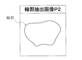
図12Cは、輪郭抽出画像P2の画像図である。図12Cにおいて、輪郭抽出画像P2は、X線透過画像P0の領域Rgの輪郭のみを抽出した画像である。画像生成部21aは、輪郭抽出画像P2を生成する機能(以後、第2機能という。)を有している。 (8-1-3)Operation 3
FIG. 12C is an image diagram of the contour extraction image P2. In FIG. 12C, the contour extraction image P2 is an image obtained by extracting only the contour of the region Rg of the X-ray transmission image P0. Theimage generation unit 21a has a function of generating a contour extraction image P2 (hereinafter referred to as a second function).
図12Cは、輪郭抽出画像P2の画像図である。図12Cにおいて、輪郭抽出画像P2は、X線透過画像P0の領域Rgの輪郭のみを抽出した画像である。画像生成部21aは、輪郭抽出画像P2を生成する機能(以後、第2機能という。)を有している。 (8-1-3)
FIG. 12C is an image diagram of the contour extraction image P2. In FIG. 12C, the contour extraction image P2 is an image obtained by extracting only the contour of the region Rg of the X-ray transmission image P0. The
なお、画像生成部21aは、輪郭を特定するため、X線透過画像P0における輝度の空間変化を輪郭として強調するエッジ処理の機能と、エッジ処理された画像において輪郭を膨張・縮小処理によって標準化する標準化機能とをさらに有している。
Note that the image generation unit 21a normalizes the contour in the edge-processed image by the expansion / contraction processing, and an edge processing function that emphasizes a spatial change of luminance in the X-ray transmission image P0 as the contour in order to specify the contour. It further has a standardization function.
(8-1-4)動作4
図12Dは、異物位置特定用画像P3の画像図である。図12Dにおいて、異物位置特定用画像P3は、輪郭抽出画像P2を異物抽出画像P1に合成し、商品Gにおける異物の位置を特定した画像である。画像生成部21aは、異物位置特定用画像P3を生成する機能(以後、第3機能という。)を有している。 (8-1-4) Operation 4
FIG. 12D is an image view of the foreign material position specifying image P3. In FIG. 12D, the foreign substance position specifying image P3 is an image in which the contour extraction image P2 is combined with the foreign substance extraction image P1 and the position of the foreign substance in the product G is specified. Theimage generation unit 21a has a function (hereinafter, referred to as a third function) of generating the foreign substance position specifying image P3.
図12Dは、異物位置特定用画像P3の画像図である。図12Dにおいて、異物位置特定用画像P3は、輪郭抽出画像P2を異物抽出画像P1に合成し、商品Gにおける異物の位置を特定した画像である。画像生成部21aは、異物位置特定用画像P3を生成する機能(以後、第3機能という。)を有している。 (8-1-4) Operation 4
FIG. 12D is an image view of the foreign material position specifying image P3. In FIG. 12D, the foreign substance position specifying image P3 is an image in which the contour extraction image P2 is combined with the foreign substance extraction image P1 and the position of the foreign substance in the product G is specified. The
なお、付加機能として、モニタ30に異物位置特定用画像P3を表示させながら、検査感度の調整を行う調整部33をモニタ30側に備えてもよい。
As an additional function, the monitor 30 may be provided with an adjustment unit 33 that adjusts the inspection sensitivity while displaying the foreign substance position specifying image P3 on the monitor 30.
(8-1-5)動作5
画像生成部21aは、輪郭抽出画像P2及び異物位置特定用画像P3上の輪郭線を着色する、或いは輪郭線の内側を着色する着色機能をさらに有しているので、この機能によって、輪郭線を着色するか、或いは輪郭線の内側を着色することができ、視認性を良くし、作業効率の向上を図ることができる。 (8-1-5) Operation 5
Theimage generation unit 21a further has a coloring function of coloring the outlines on the outline extraction image P2 and the foreign substance position specifying image P3 or coloring the inside of the outlines. It is possible to color or to color the inside of the outline, to improve the visibility and to improve the working efficiency.
画像生成部21aは、輪郭抽出画像P2及び異物位置特定用画像P3上の輪郭線を着色する、或いは輪郭線の内側を着色する着色機能をさらに有しているので、この機能によって、輪郭線を着色するか、或いは輪郭線の内側を着色することができ、視認性を良くし、作業効率の向上を図ることができる。 (8-1-5) Operation 5
The
(8-2)動作の制御フロー
図13は、他の実施形態における異物位置特定用画像P3の自動生成制御のフローチャートである。図13において、制御コンピュータ20は画像生成部21aを介して以下の制御を行う。 (8-2) Control Flow of Operation FIG. 13 is a flowchart of automatic generation control of the foreign substance position specifying image P3 in another embodiment. In FIG. 13, thecontrol computer 20 performs the following control via the image generation unit 21a.
図13は、他の実施形態における異物位置特定用画像P3の自動生成制御のフローチャートである。図13において、制御コンピュータ20は画像生成部21aを介して以下の制御を行う。 (8-2) Control Flow of Operation FIG. 13 is a flowchart of automatic generation control of the foreign substance position specifying image P3 in another embodiment. In FIG. 13, the
(ステップS11)
先ず、制御コンピュータ20は、ステップS11で異物位置特定用画像P3の生成指令の有無を判定し、指令があったときはステップS12に進み、指令がないときは異物位置特定用画像P3の生成指令の有無の判定を継続する。 (Step S11)
First, in step S11, thecontrol computer 20 determines the presence / absence of an instruction to generate the foreign object position specifying image P3. When there is an instruction, the process proceeds to step S12, and when there is no instruction, the instruction to generate the foreign object position specifying image P3. Continue to determine the presence or absence of
先ず、制御コンピュータ20は、ステップS11で異物位置特定用画像P3の生成指令の有無を判定し、指令があったときはステップS12に進み、指令がないときは異物位置特定用画像P3の生成指令の有無の判定を継続する。 (Step S11)
First, in step S11, the
(ステップS12)
次に、制御コンピュータ20は、ステップS12で対象となるX線データを読み込み、ステップS13に進む。 (Step S12)
Next, thecontrol computer 20 reads the target X-ray data in step S12, and proceeds to step S13.
次に、制御コンピュータ20は、ステップS12で対象となるX線データを読み込み、ステップS13に進む。 (Step S12)
Next, the
(ステップS13)
次に、制御コンピュータ20は、ステップS13でX線透過画像P0を生成し、ステップS14に進む。 (Step S13)
Next, thecontrol computer 20 generates an X-ray transmission image P0 in step S13, and proceeds to step S14.
次に、制御コンピュータ20は、ステップS13でX線透過画像P0を生成し、ステップS14に進む。 (Step S13)
Next, the
(ステップS14)
次に、制御コンピュータ20は、ステップS14で異物抽出画像P1を生成し、ステップS15に進む。 (Step S14)
Next, thecontrol computer 20 generates a foreign matter extraction image P1 in step S14, and proceeds to step S15.
次に、制御コンピュータ20は、ステップS14で異物抽出画像P1を生成し、ステップS15に進む。 (Step S14)
Next, the
(ステップS15)
次に、制御コンピュータ20は、ステップS15で輪郭抽出画像P2を作成し、ステップS16に進む。 (Step S15)
Next, thecontrol computer 20 creates a contour extraction image P2 in step S15, and proceeds to step S16.
次に、制御コンピュータ20は、ステップS15で輪郭抽出画像P2を作成し、ステップS16に進む。 (Step S15)
Next, the
(ステップS16)
次に、制御コンピュータ20は、ステップS16で異物抽出画像P1に輪郭抽出画像P2を合成して異物位置特定用画像P3を生成する。 (Step S16)
Next, in step S16, thecontrol computer 20 combines the contour extraction image P2 with the foreign material extraction image P1 to generate a foreign material position specifying image P3.
次に、制御コンピュータ20は、ステップS16で異物抽出画像P1に輪郭抽出画像P2を合成して異物位置特定用画像P3を生成する。 (Step S16)
Next, in step S16, the
(ステップS17)
次に、制御コンピュータ20は、ステップS17で異物位置特定用画像P3の輪郭を着色する指令の有無を判定し、指令があったときはステップS18進み、指令がないときは制御を終了する。 (Step S17)
Next, in step S17, thecontrol computer 20 determines the presence or absence of an instruction to color the contour of the foreign substance position specifying image P3. If there is an instruction, the process proceeds to step S18. If there is no instruction, the control is ended.
次に、制御コンピュータ20は、ステップS17で異物位置特定用画像P3の輪郭を着色する指令の有無を判定し、指令があったときはステップS18進み、指令がないときは制御を終了する。 (Step S17)
Next, in step S17, the
(ステップS18)
そして、制御コンピュータ20は、ステップS18で異物位置特定用画像P3の物品の輪郭を着色し、制御を終了する。 (Step S18)
Then, in step S18, thecontrol computer 20 colors the outline of the article in the foreign substance position specifying image P3 and ends the control.
そして、制御コンピュータ20は、ステップS18で異物位置特定用画像P3の物品の輪郭を着色し、制御を終了する。 (Step S18)
Then, in step S18, the
(9)その他
ここでは、上記実施形態で説明しなかったCPU21の他の構成について説明する。図14は、他の実施形態における制御コンピュータのブロック構成図である。図14において、制御コンピュータ20のCPU21は、上記実施形態で説明した画像生成部21a、領域判別部21b、異物検査部21cおよび総合診断部21d(図4参照)以外に、重量推定部21e及び重量診断部21fを有している。 (9) Others Here, another configuration of theCPU 21 which has not been described in the above embodiment will be described. FIG. 14 is a block diagram of a control computer according to another embodiment. In FIG. 14, the CPU 21 of the control computer 20 is not limited to the weight estimation unit 21e and the weight other than the image generation unit 21a, the area determination unit 21b, the foreign matter inspection unit 21c and the comprehensive diagnosis unit 21d (see FIG. 4) described in the above embodiment. It has a diagnosis unit 21f.
ここでは、上記実施形態で説明しなかったCPU21の他の構成について説明する。図14は、他の実施形態における制御コンピュータのブロック構成図である。図14において、制御コンピュータ20のCPU21は、上記実施形態で説明した画像生成部21a、領域判別部21b、異物検査部21cおよび総合診断部21d(図4参照)以外に、重量推定部21e及び重量診断部21fを有している。 (9) Others Here, another configuration of the
(9-1)重量推定部21e
重量推定部21eは、領域判別部21bにより判別された商品領域に対して画像処理を施すことにより、商品Gの重量を推定する。当該重量推定処理は、X線透過画像P上においてはX線の照射方向に厚みのある物質ほど暗く写るという性質を利用し、以下の原理に基づいて行われる。 (9-1)Weight estimation unit 21e
Theweight estimation unit 21e estimates the weight of the product G by performing image processing on the product region determined by the region determination unit 21b. The weight estimation processing is performed on the X-ray transmission image P using the property that the thicker the material in the irradiation direction of the X-ray is, the darker it is, and it is performed based on the following principle.
重量推定部21eは、領域判別部21bにより判別された商品領域に対して画像処理を施すことにより、商品Gの重量を推定する。当該重量推定処理は、X線透過画像P上においてはX線の照射方向に厚みのある物質ほど暗く写るという性質を利用し、以下の原理に基づいて行われる。 (9-1)
The
X線透過画像P上の厚さtの物質を写す画素の明るさIは、物質の存在しない領域に含まれる画素の明るさをI0とした場合、以下の式(1)によって表される。
The brightness I of a pixel for copying a substance of thickness t on the X-ray transmission image P is represented by the following formula (1), where the brightness of the pixel contained in the area where no substance is present is I 0 .
I/I0=e-μt ・・・(1)
ここで、μは、X線のエネルギーと物質の種類とに応じて定まる線吸収係数である。式(1)を物質の厚さtについて解くと、以下の式(2)のようになる。 I / I 0 = e- μt (1)
Here, μ is a linear absorption coefficient determined according to the energy of the X-ray and the type of the substance. If Equation (1) is solved for the thickness t of a substance, Equation (2) below is obtained.
t=-1/μ×ln(I/I0) ・・・(2)
また、内容物の微小部位の重量は、当該微小部位の厚さに比例する。したがって、明るさIの画素の写す内容物の微小部位の重量mは、適当な定数αを用いて、以下の式(3)によって近似的に算出される。 t = -1 / μ × ln (I / I 0 ) (2)
Moreover, the weight of the micro area of the content is proportional to the thickness of the micro area. Therefore, the weight m of the minute portion of the contents copied by the pixel of brightness I is approximately calculated by the following equation (3) using an appropriate constant α.
m=-αln(I/I0) ・・・(3)
重量推定部21eは、商品Gを構成する全ての画素に対応する重量mを算出して足し合わせることにより、商品G全体の重量を推定する。 m = -α ln (I / I 0 ) (3)
Theweight estimation unit 21 e estimates the weight of the entire product G by calculating and adding weights m corresponding to all the pixels constituting the product G.
重量推定部21eは、商品Gを構成する全ての画素に対応する重量mを算出して足し合わせることにより、商品G全体の重量を推定する。 m = -α ln (I / I 0 ) (3)
The
(9-2)重量診断部21f
重量診断部21fは、商品Gの内容物の重量が所定の範囲内に収まっているか否かをチェックする。そして、重量が当該範囲内に収まっている場合には、その商品Gを正常と診断し、当該範囲内に収まっていない場合には、その商品Gを重量異常と診断する。 (9-2) Weightdiagnostic unit 21f
The weightdiagnostic unit 21 f checks whether the weight of the content of the product G is within a predetermined range. Then, when the weight is within the range, the product G is diagnosed as normal, and when the weight is not within the range, the product G is diagnosed as weight abnormality.
重量診断部21fは、商品Gの内容物の重量が所定の範囲内に収まっているか否かをチェックする。そして、重量が当該範囲内に収まっている場合には、その商品Gを正常と診断し、当該範囲内に収まっていない場合には、その商品Gを重量異常と診断する。 (9-2) Weight
The weight
なお、重量診断部21fによる処理は、重量推定部21eによる処理に遅れて並列に実行される。
The processing by the weight diagnosis unit 21 f is performed in parallel behind the processing by the weight estimation unit 21 e.
本発明は、物品に光を照射する光照射部と、その光に基づいて物品の画像を生成する画像生成部と、画像生成部により生成された画像に基づいて前記物品における不良の有無を判断する判断部とを備える検査装置であれば、X線検査装置以外の検査装置にも有用である。
The present invention determines the presence or absence of a defect in the article based on a light emitting unit that emits light to the article, an image generation unit that generates an image of the article based on the light, and an image generated by the image generation unit. If it is an inspection apparatus provided with the judgment part which makes it, it is useful also to inspection apparatuses other than X-ray inspection apparatus.
10 X線検査装置(検査装置)
13 X線照射器(光照射部)
21a 画像生成部
21f 総合診断部(判断部)
101 第1作業部(作業部)
102 第2作業部(作業部)
111 第1表示部(表示部)
112 第2表示部(表示部)
P3 異物位置特定画像(画像) 10 X-ray inspection device (inspection device)
13 X-ray irradiator (light irradiator)
21aimage generation unit 21f comprehensive diagnosis unit (determination unit)
101 First Working Unit (Working Unit)
102 Second Working Unit (Working Unit)
111 1st display part (display part)
112 2nd display part (display part)
P3 Foreign matter position identification image (image)
13 X線照射器(光照射部)
21a 画像生成部
21f 総合診断部(判断部)
101 第1作業部(作業部)
102 第2作業部(作業部)
111 第1表示部(表示部)
112 第2表示部(表示部)
P3 異物位置特定画像(画像) 10 X-ray inspection device (inspection device)
13 X-ray irradiator (light irradiator)
21a
101 First Working Unit (Working Unit)
102 Second Working Unit (Working Unit)
111 1st display part (display part)
112 2nd display part (display part)
P3 Foreign matter position identification image (image)
Claims (8)
- 物品に光を照射する光照射部と、前記光に基づいて前記物品の画像を生成する画像生成部と、前記画像生成部により生成された前記画像に基づいて前記物品における不良の有無を判断する判断部と、を備える検査装置であって、
作業員が異物の除去作業を行う作業部と、
前記判断部で不良と判断された前記物品である作業対象物を前記作業部に振り分ける振分機構と、
前記作業対象物が振り分けられた前記作業部において、前記作業員が視認可能に、当該作業対象物の前記画像を表示させる表示部と、
をさらに備える、
検査装置。 A light emitting unit for emitting light to an article, an image generation unit for generating an image of the article based on the light, and the presence or absence of a defect in the article based on the image generated by the image generation unit An inspection apparatus comprising: a determination unit;
A working unit where workers remove foreign objects;
A distribution mechanism that distributes, to the working unit, a work target that is the article determined to be defective by the determination unit;
A display unit configured to display the image of the work object in the work unit to which the work object has been distributed so that the worker can visually recognize the work object;
Further comprising
Inspection device. - 前記表示部は、前記作業部ごとに設けられている、
請求項1に記載の検査装置。 The display unit is provided for each of the working units.
The inspection apparatus according to claim 1. - 前記表示部は、複数の前記作業部に共通の1つの表示手段である、
請求項1に記載の検査装置。 The display unit is one display unit common to a plurality of the working units.
The inspection apparatus according to claim 1. - 作業対象の前記画像を固定して表示する、
請求項1から請求項3のいずれか1項に記載の検査装置。 Fix and display the image of the work object,
The inspection apparatus according to any one of claims 1 to 3. - 前記表示部は、1つの前記作業部に振り分けられた複数の前記作業対象物の画像を分割して表示する、
請求項1から請求項4のいずれか1項に記載の検査装置。 The display unit divides and displays images of the plurality of work objects distributed to one work unit.
The inspection apparatus according to any one of claims 1 to 4. - 前記表示部は、反転させた前記作業対象物の画像を表示する、
請求項1から請求項5のいずれか1項に記載の検査装置。 The display unit displays an image of the work object inverted.
The inspection apparatus according to any one of claims 1 to 5. - 前記光は、X線である、
請求項1から請求項6のいずれか1項に記載の検査装置。 The light is an x-ray,
The inspection apparatus according to any one of claims 1 to 6. - 前記作業対象物は、前記作業部で異物除去を行うために異物の有無が検査された食品である、
請求項1から請求項7のいずれか1項に記載の検査装置。 The work object is a food whose presence or absence has been inspected in order to remove foreign matter in the work unit,
The inspection apparatus according to any one of claims 1 to 7.
Applications Claiming Priority (2)
| Application Number | Priority Date | Filing Date | Title |
|---|---|---|---|
| JP2017241905A JP7239960B2 (en) | 2017-12-18 | 2017-12-18 | inspection equipment |
| JP2017-241905 | 2017-12-18 |
Publications (1)
| Publication Number | Publication Date |
|---|---|
| WO2019123802A1 true WO2019123802A1 (en) | 2019-06-27 |
Family
ID=66994559
Family Applications (1)
| Application Number | Title | Priority Date | Filing Date |
|---|---|---|---|
| PCT/JP2018/038614 WO2019123802A1 (en) | 2017-12-18 | 2018-10-17 | Inspection device |
Country Status (2)
| Country | Link |
|---|---|
| JP (1) | JP7239960B2 (en) |
| WO (1) | WO2019123802A1 (en) |
Families Citing this family (1)
| Publication number | Priority date | Publication date | Assignee | Title |
|---|---|---|---|---|
| JP2021025874A (en) * | 2019-08-05 | 2021-02-22 | 株式会社イシダ | Inspection device |
Citations (3)
| Publication number | Priority date | Publication date | Assignee | Title |
|---|---|---|---|---|
| JP2011089965A (en) * | 2009-10-26 | 2011-05-06 | Ishida Co Ltd | Article inspection device |
| WO2014079448A1 (en) * | 2012-11-22 | 2014-05-30 | Attec Danmark A/S | A method and a means for controlling and allowing removal of foreign matter from food products |
| JP2017138193A (en) * | 2016-02-03 | 2017-08-10 | アンリツインフィビス株式会社 | Article inspection device |
Family Cites Families (6)
| Publication number | Priority date | Publication date | Assignee | Title |
|---|---|---|---|---|
| JP2002162705A (en) | 2000-11-24 | 2002-06-07 | Konica Corp | Phase contrast radiation image processor |
| JP4429635B2 (en) | 2003-06-04 | 2010-03-10 | 株式会社日立メディコ | Medical image diagnostic apparatus and operation information display method thereof |
| JP2013088165A (en) | 2011-10-14 | 2013-05-13 | Ishida Co Ltd | X-ray inspection apparatus |
| JP6022860B2 (en) | 2012-08-31 | 2016-11-09 | 株式会社イシダ | Article inspection apparatus and article inspection method |
| JP6747771B2 (en) | 2015-01-26 | 2020-08-26 | コニカミノルタ株式会社 | Image display device and image display method |
| JP6200562B2 (en) | 2016-08-25 | 2017-09-20 | 富士フイルムRiファーマ株式会社 | Image processing apparatus, method, and computer program |
-
2017
- 2017-12-18 JP JP2017241905A patent/JP7239960B2/en active Active
-
2018
- 2018-10-17 WO PCT/JP2018/038614 patent/WO2019123802A1/en active Application Filing
Patent Citations (3)
| Publication number | Priority date | Publication date | Assignee | Title |
|---|---|---|---|---|
| JP2011089965A (en) * | 2009-10-26 | 2011-05-06 | Ishida Co Ltd | Article inspection device |
| WO2014079448A1 (en) * | 2012-11-22 | 2014-05-30 | Attec Danmark A/S | A method and a means for controlling and allowing removal of foreign matter from food products |
| JP2017138193A (en) * | 2016-02-03 | 2017-08-10 | アンリツインフィビス株式会社 | Article inspection device |
Also Published As
| Publication number | Publication date |
|---|---|
| JP7239960B2 (en) | 2023-03-15 |
| JP2019107605A (en) | 2019-07-04 |
Similar Documents
| Publication | Publication Date | Title |
|---|---|---|
| CN101750033A (en) | X-ray inspection apparatus | |
| WO2019159440A1 (en) | Inspection device | |
| US7477726B2 (en) | X-ray inspection apparatus | |
| EP2163886A1 (en) | X-ray inspection device and production system | |
| KR20200097344A (en) | Inspection device | |
| JP3828781B2 (en) | X-ray foreign object detection device | |
| JP5864404B2 (en) | X-ray inspection equipment | |
| WO2019123802A1 (en) | Inspection device | |
| WO2021193733A1 (en) | Training data generation device, inspection device, and program | |
| JP2005003480A (en) | X-ray examination apparatus | |
| JP2002098653A (en) | X-ray inspection device | |
| JP2019107605A5 (en) | ||
| JP2015137858A (en) | Inspection device | |
| WO2017159855A1 (en) | X-ray inspection device | |
| JP2009168590A (en) | X-ray inspection device | |
| JP6346753B2 (en) | Package inspection equipment | |
| JP2007322344A (en) | X-ray inspection device | |
| EP3800468A1 (en) | Inspection device | |
| JP2005031069A (en) | X-ray inspection apparatus | |
| JP2009080031A (en) | X-ray inspection device | |
| WO2017159856A1 (en) | X-ray inspection apparatus | |
| JP3511505B2 (en) | X-ray inspection equipment | |
| JP4005117B2 (en) | X-ray inspection equipment | |
| JP4081054B2 (en) | X-ray inspection equipment | |
| JP5336758B2 (en) | X-ray inspection equipment |
Legal Events
| Date | Code | Title | Description |
|---|---|---|---|
| 121 | Ep: the epo has been informed by wipo that ep was designated in this application |
Ref document number: 18892841 Country of ref document: EP Kind code of ref document: A1 |
|
| NENP | Non-entry into the national phase |
Ref country code: DE |
|
| 122 | Ep: pct application non-entry in european phase |
Ref document number: 18892841 Country of ref document: EP Kind code of ref document: A1 |