WO2021193733A1 - Training data generation device, inspection device, and program - Google Patents
Training data generation device, inspection device, and program Download PDFInfo
- Publication number
- WO2021193733A1 WO2021193733A1 PCT/JP2021/012284 JP2021012284W WO2021193733A1 WO 2021193733 A1 WO2021193733 A1 WO 2021193733A1 JP 2021012284 W JP2021012284 W JP 2021012284W WO 2021193733 A1 WO2021193733 A1 WO 2021193733A1
- Authority
- WO
- WIPO (PCT)
- Prior art keywords
- image
- inspection
- teacher data
- learning
- display
- Prior art date
Links
- 238000007689 inspection Methods 0.000 title claims abstract description 308
- 238000012549 training Methods 0.000 title abstract description 8
- 238000000034 method Methods 0.000 claims abstract description 57
- 230000002159 abnormal effect Effects 0.000 claims abstract description 30
- 238000012545 processing Methods 0.000 claims abstract description 20
- 238000013500 data storage Methods 0.000 claims abstract description 15
- 238000010801 machine learning Methods 0.000 claims description 37
- 238000000605 extraction Methods 0.000 claims description 30
- 230000032258 transport Effects 0.000 claims description 16
- 238000001514 detection method Methods 0.000 claims description 12
- 239000000284 extract Substances 0.000 claims description 8
- 238000002955 isolation Methods 0.000 abstract 2
- 238000004458 analytical method Methods 0.000 description 6
- 230000005540 biological transmission Effects 0.000 description 5
- 230000008569 process Effects 0.000 description 5
- 230000005856 abnormality Effects 0.000 description 4
- 238000010586 diagram Methods 0.000 description 4
- 230000037303 wrinkles Effects 0.000 description 3
- 230000007547 defect Effects 0.000 description 2
- 230000002950 deficient Effects 0.000 description 2
- 230000006870 function Effects 0.000 description 2
- 238000003384 imaging method Methods 0.000 description 2
- 230000001678 irradiating effect Effects 0.000 description 2
- 230000002238 attenuated effect Effects 0.000 description 1
- 239000003086 colorant Substances 0.000 description 1
- 238000004590 computer program Methods 0.000 description 1
- 238000011109 contamination Methods 0.000 description 1
- 238000013527 convolutional neural network Methods 0.000 description 1
- 238000013135 deep learning Methods 0.000 description 1
- 238000013461 design Methods 0.000 description 1
- 238000011161 development Methods 0.000 description 1
- 239000003814 drug Substances 0.000 description 1
- 230000000694 effects Effects 0.000 description 1
- 238000005516 engineering process Methods 0.000 description 1
- 235000013305 food Nutrition 0.000 description 1
- 238000010191 image analysis Methods 0.000 description 1
- 230000001771 impaired effect Effects 0.000 description 1
- 230000010354 integration Effects 0.000 description 1
- 239000004973 liquid crystal related substance Substances 0.000 description 1
- 238000012986 modification Methods 0.000 description 1
- 230000004048 modification Effects 0.000 description 1
- 238000003062 neural network model Methods 0.000 description 1
- 238000004806 packaging method and process Methods 0.000 description 1
- 230000004044 response Effects 0.000 description 1
- 238000012546 transfer Methods 0.000 description 1
- 238000002834 transmittance Methods 0.000 description 1
Images


Classifications
-
- G—PHYSICS
- G06—COMPUTING; CALCULATING OR COUNTING
- G06T—IMAGE DATA PROCESSING OR GENERATION, IN GENERAL
- G06T7/00—Image analysis
- G06T7/0002—Inspection of images, e.g. flaw detection
- G06T7/0004—Industrial image inspection
-
- G—PHYSICS
- G01—MEASURING; TESTING
- G01N—INVESTIGATING OR ANALYSING MATERIALS BY DETERMINING THEIR CHEMICAL OR PHYSICAL PROPERTIES
- G01N23/00—Investigating or analysing materials by the use of wave or particle radiation, e.g. X-rays or neutrons, not covered by groups G01N3/00 – G01N17/00, G01N21/00 or G01N22/00
- G01N23/02—Investigating or analysing materials by the use of wave or particle radiation, e.g. X-rays or neutrons, not covered by groups G01N3/00 – G01N17/00, G01N21/00 or G01N22/00 by transmitting the radiation through the material
- G01N23/04—Investigating or analysing materials by the use of wave or particle radiation, e.g. X-rays or neutrons, not covered by groups G01N3/00 – G01N17/00, G01N21/00 or G01N22/00 by transmitting the radiation through the material and forming images of the material
-
- G—PHYSICS
- G06—COMPUTING; CALCULATING OR COUNTING
- G06N—COMPUTING ARRANGEMENTS BASED ON SPECIFIC COMPUTATIONAL MODELS
- G06N20/00—Machine learning
-
- G—PHYSICS
- G06—COMPUTING; CALCULATING OR COUNTING
- G06T—IMAGE DATA PROCESSING OR GENERATION, IN GENERAL
- G06T7/00—Image analysis
- G06T7/0002—Inspection of images, e.g. flaw detection
- G06T7/0004—Industrial image inspection
- G06T7/001—Industrial image inspection using an image reference approach
-
- G—PHYSICS
- G01—MEASURING; TESTING
- G01N—INVESTIGATING OR ANALYSING MATERIALS BY DETERMINING THEIR CHEMICAL OR PHYSICAL PROPERTIES
- G01N2223/00—Investigating materials by wave or particle radiation
- G01N2223/40—Imaging
- G01N2223/401—Imaging image processing
-
- G—PHYSICS
- G01—MEASURING; TESTING
- G01N—INVESTIGATING OR ANALYSING MATERIALS BY DETERMINING THEIR CHEMICAL OR PHYSICAL PROPERTIES
- G01N2223/00—Investigating materials by wave or particle radiation
- G01N2223/60—Specific applications or type of materials
- G01N2223/643—Specific applications or type of materials object on conveyor
-
- G—PHYSICS
- G06—COMPUTING; CALCULATING OR COUNTING
- G06T—IMAGE DATA PROCESSING OR GENERATION, IN GENERAL
- G06T2207/00—Indexing scheme for image analysis or image enhancement
- G06T2207/10—Image acquisition modality
- G06T2207/10116—X-ray image
-
- G—PHYSICS
- G06—COMPUTING; CALCULATING OR COUNTING
- G06T—IMAGE DATA PROCESSING OR GENERATION, IN GENERAL
- G06T2207/00—Indexing scheme for image analysis or image enhancement
- G06T2207/20—Special algorithmic details
- G06T2207/20021—Dividing image into blocks, subimages or windows
-
- G—PHYSICS
- G06—COMPUTING; CALCULATING OR COUNTING
- G06T—IMAGE DATA PROCESSING OR GENERATION, IN GENERAL
- G06T2207/00—Indexing scheme for image analysis or image enhancement
- G06T2207/20—Special algorithmic details
- G06T2207/20081—Training; Learning
-
- G—PHYSICS
- G06—COMPUTING; CALCULATING OR COUNTING
- G06T—IMAGE DATA PROCESSING OR GENERATION, IN GENERAL
- G06T2207/00—Indexing scheme for image analysis or image enhancement
- G06T2207/20—Special algorithmic details
- G06T2207/20084—Artificial neural networks [ANN]
Abstract
The present invention efficiently generates training data for generating a trained model to be used in quality determination during inspections for trapped contents, or the like, and performs inspections. A training data generation device according to the present invention comprises: an isolation means that receives the input of an image in which an inspection target appears, uses a prescribed method to specify, in the image, an inspection range for the inspection target, and isolates the specified inspection range from the image; a sorting processing means that, on the basis of a sorting operation in which the image of the inspection range that was isolated by the isolation means is treated as an image to be learned and is sorted at least as either normal or abnormal, associates the image to be learned and the sorting result; and a training data storage unit that stores training data in which the image to be learned and the sorting result are associated.
Description
本発明は、被検査物を撮影した画像に基づき被検査物を検査する検査装置において、被検査物の良否判定を行うための学習済みモデルを生成すべく機械学習させる教師データを生成して検査を実行するための教師データ生成装置、検査装置及びプログラムに関する。
The present invention generates and inspects teacher data for machine learning to generate a trained model for determining the quality of an inspected object in an inspection device that inspects the inspected object based on an image obtained by photographing the inspected object. Regarding teacher data generators, inspection devices and programs for executing.
X線検査装置は、X線発生部とX線検出部とを対向させ、これらの間を通るように被検査物をコンベア等の搬送装置で順次搬送し、被検査物がX線発生部とX線検出部との間を通過する際に得られるX線透過データを用いて、被検査物のX線透過画像を生成し、当該X線透過画像を用いて被検査物を非破壊で検査する装置である。その用途としては、例えば、包装された商品の内容物に異物が混入していないかを検査する異物混入検査、内容物が所定の個数を備えているかを検査する個数検査、内容物にひび割れ等の欠陥が発生していないかを検査する欠陥検査などがある。これらの検査は食品、医薬品、工業部品等の様々な物品に対して行われる。また、X線検査装置以外にも、被検査物を撮影した画像に基づき被検査物を検査する検査装置が実用化されている。
In the X-ray inspection device, the X-ray generator and the X-ray detector are opposed to each other, and the object to be inspected is sequentially conveyed by a transfer device such as a conveyor so as to pass between them, and the object to be inspected is the X-ray generator. An X-ray transmission image of the object to be inspected is generated using the X-ray transmission data obtained when passing between the X-ray detection unit, and the X-ray transmission image is used to inspect the object to be inspected non-destructively. It is a device to do. Applications include, for example, foreign matter contamination inspection to inspect whether foreign matter is mixed in the contents of the packaged product, number inspection to inspect whether the contents have a predetermined number, cracks in the contents, etc. There is a defect inspection that inspects whether or not a defect has occurred. These inspections are performed on various articles such as foods, pharmaceuticals and industrial parts. In addition to the X-ray inspection device, an inspection device that inspects the inspected object based on a photographed image of the inspected object has been put into practical use.
この種の検査装置では、所定の判定基準に基づき、被検査物を良品と不良品とに振り分ける。従来、この判定基準は予め定義されたものであったが、昨今の機械学習技術の発達により、学習プログラムに学習用データ(教師データ)を入力することにより生成される学習済みモデルを判定基準として用いるものが提案されている(例えば特許文献1を参照)。
In this type of inspection device, the inspected item is classified into a non-defective item and a defective item based on a predetermined judgment standard. Conventionally, this criterion was defined in advance, but with the recent development of machine learning technology, a trained model generated by inputting learning data (teacher data) into a learning program is used as a criterion. Those to be used have been proposed (see, for example, Patent Document 1).
包装袋のシール部分における噛み込み等の検査時の良否判定の際にも、学習済みモデルを判定基準として用いることが可能であるが、学習済みモデルを生成するために学習用プログラムに入力する学習用データの効率的な収集方法が未だ確立されていない。
It is possible to use the trained model as a judgment criterion when judging the quality of the seal part of the packaging bag at the time of inspection such as biting, but learning to input to the learning program to generate the trained model. An efficient method for collecting data for use has not yet been established.
本発明は上記の課題に鑑みてなされたものであり、噛み込み等の検査時の良否判定に用いる学習済みモデルを生成するための教師データを効率的に生成して検査を実行することが可能な教師データ生成装置、検査装置及びプログラムを提供することを目的とする。
The present invention has been made in view of the above problems, and it is possible to efficiently generate teacher data for generating a trained model used for quality judgment at the time of inspection such as biting and execute the inspection. It is an object of the present invention to provide a teacher data generation device, an inspection device and a program.
本発明の教師データ生成装置は機械学習に用いられる教師データを生成する。教師データ生成装置が生成した教師データを用いて機械学習により生成される学習済みモデルは、検査対象物が写る画像から切り出された判定対象画像を当該学習済みモデルに入力し、出力された判定結果に基づき検査対象物が正常である否かの検査を行う検査装置で用いられるものである。教師データ生成装置は、検査対象物が写る画像の入力を受け付け、当該画像において検査対象物の検査範囲を所定の方法により特定し、特定された検査範囲を当該画像から切り出す切り出し手段と、切り出し手段において切り出された検査範囲の画像を学習対象画像として、少なくとも正常と非正常のいずれかに振り分ける振分操作に基づき、学習対象画像と振り分けの結果とを対応付ける振分処理手段と、学習対象画像と振り分けの結果とが対応付けられた教師データを記憶する教師データ記憶部とを備える。
The teacher data generator of the present invention generates teacher data used for machine learning. The trained model generated by machine learning using the teacher data generated by the teacher data generator inputs the judgment target image cut out from the image showing the inspection target into the trained model, and outputs the judgment result. It is used in an inspection device that inspects whether or not the inspection object is normal based on the above. The teacher data generation device accepts the input of an image showing the inspection object, specifies the inspection range of the inspection target in the image by a predetermined method, and cuts out the specified inspection range from the image, and the cutting means. Based on the sorting operation of sorting the image of the inspection range cut out in the above into at least normal or abnormal, the sorting processing means for associating the learning target image with the sorting result, and the learning target image It is provided with a teacher data storage unit that stores teacher data associated with the distribution result.
本発明の教師データ生成装置では、検査範囲を、入力された1以上の基準点の位置情報及び基準点からの距離を示す情報に基づき特定してもよい。
In the teacher data generation device of the present invention, the inspection range may be specified based on the input position information of one or more reference points and the information indicating the distance from the reference point.
また、検査範囲は、画像の明暗の所定の閾値に基づき画像を二値化し、二値化された画像から検出されたブロブに基づき特定してもよい。
Further, the inspection range may be specified based on the blob detected from the binarized image by binarizing the image based on a predetermined threshold value of the lightness and darkness of the image.
本発明の教師データ生成装置では、切り出し手段において切り出された検査範囲の画像から、より小さい部分画像を抽出する抽出手段を更に備え、振分処理手段が、部分画像を学習対象画像として、少なくとも正常と非正常のいずれかに振り分ける振分操作に基づき、部分画像と振り分けの結果とを対応付けてもよい。
The teacher data generation device of the present invention further includes an extraction means for extracting a smaller partial image from the image of the inspection range cut out by the cutting means, and the sorting processing means is at least normal with the partial image as the image to be learned. The partial image and the result of the distribution may be associated with each other based on the distribution operation of the distribution to either the normal or the abnormal.
本発明の教師データ生成装置では、抽出手段は、隣接する部分画像と部分的に重複するように複数の部分画像を抽出してもよい。
In the teacher data generation device of the present invention, the extraction means may extract a plurality of partial images so as to partially overlap the adjacent partial images.
本発明の教師データ生成装置では、ディスプレイと、ディスプレイによる表示を制御する表示制御手段とを更に備え、表示制御手段は、ディスプレイの第1領域に複数の学習対象画像を並べて表示させるとともに、ディスプレイの第2領域に検査対象物の画像を、学習対象画像に対応する領域を指し示す表示を重畳しつつ表示させてもよい。
The teacher data generation device of the present invention further includes a display and a display control means for controlling the display by the display, and the display control means displays a plurality of learning target images side by side in the first area of the display and displays the display. The image of the inspection target may be displayed on the second region while superimposing a display indicating the region corresponding to the learning target image.
本発明の教師データ生成装置では、表示制御手段は、ディスプレイの第1領域に表示された複数の学習対象画像のうちの1つが選択されると、ディスプレイの第2領域に表示された検査対象物の画像における当該選択された学習対象画像に対応する領域を指し示す表示をさせてもよい。
In the teacher data generation device of the present invention, when one of the plurality of learning target images displayed in the first area of the display is selected, the display control means displays the inspection object displayed in the second area of the display. The display may indicate the area corresponding to the selected image to be learned in the image of.
本発明の検査装置は、検査対象物を搬送し、検査領域を通過させる搬送部と、電磁波を検査領域に照射する電磁波照射部と、搬送部を挟んで電磁波照射部と対向する位置に配置され、検査領域を通過する検査対象物を透過した電磁波を検出する電磁波検出部と、電磁波検出部で検出された電磁波の強度の分布を2次元の画像として構成する画像構成手段と、画像構成手段において構成された検査対象物が写る画像において、検査対象物の検査範囲を所定の方法により特定し、特定された検査範囲を画像から切り出す切り出し手段と、切り出し手段において切り出された検査範囲の画像を判定対象画像として学習済みモデルに入力して、出力された判定結果に基づき検査対象物が正常であるか否かの検査を行う判定手段と、を備える。
The inspection device of the present invention is arranged at a position facing the electromagnetic wave irradiation unit with the transport unit sandwiched between the transport unit that transports the inspection object and passes it through the inspection region, the electromagnetic wave irradiation unit that irradiates the inspection region with electromagnetic waves. In the electromagnetic wave detecting unit that detects the electromagnetic wave transmitted through the inspection object passing through the inspection area, the image forming means that configures the distribution of the intensity of the electromagnetic wave detected by the electromagnetic wave detecting unit as a two-dimensional image, and the image forming means. In the image showing the configured inspection object, the inspection range of the inspection object is specified by a predetermined method, and the cutout means for cutting out the specified inspection range from the image and the image of the inspection range cut out by the cutting means are determined. It is provided with a determination means for inputting the trained model as an object image and inspecting whether or not the inspection object is normal based on the output determination result.
本発明の検査装置では、検査範囲を、入力された1以上の基準点の位置情報及び基準点からの距離を示す情報に基づき特定してもよい。
In the inspection device of the present invention, the inspection range may be specified based on the input position information of one or more reference points and the information indicating the distance from the reference point.
また、検査範囲は、画像の明暗の所定の閾値に基づき画像を二値化し、二値化された画像から検出されたブロブに基づき特定してもよい。
Further, the inspection range may be specified based on the blob detected from the binarized image by binarizing the image based on a predetermined threshold value of the lightness and darkness of the image.
本発明の検査装置では、切り出し手段において切り出された検査範囲の画像から、より小さい部分画像を抽出する抽出手段を更に備え、判定手段が、部分画像を判定対象画像として学習済みモデルに入力して検査対象物の検査を行ってもよい。
The inspection apparatus of the present invention further includes an extraction means for extracting a smaller partial image from the image of the inspection range cut out by the cutting means, and the determination means inputs the partial image as the determination target image into the trained model. The inspection object may be inspected.
本発明の検査装置では、抽出手段は、隣接する部分画像と部分的に重複するように複数の部分画像を抽出してもよい。
In the inspection apparatus of the present invention, the extraction means may extract a plurality of partial images so as to partially overlap the adjacent partial images.
本発明の検査装置では、学習済みモデルが出力する判定結果が、入力された判定対象画像の正常性を示すスコアであり、判定手段が、当該スコアに基づき検査対象物が正常であるか否かの検査を行ってもよい。
In the inspection device of the present invention, the determination result output by the trained model is a score indicating the normality of the input determination target image, and the determination means determines whether or not the inspection object is normal based on the score. May be inspected.
本発明の検査装置では、判定対象画像が複数であり、判定手段が、それぞれの判定対象画像を学習済みモデルに入力して、それぞれの判定対象画像について出力されたスコアに基づき検査対象物が正常であるか否かの検査を行ってもよい。
In the inspection device of the present invention, there are a plurality of judgment target images, the judgment means inputs each judgment target image into the trained model, and the inspection target is normal based on the score output for each judgment target image. You may inspect whether or not it is.
本発明の教師データ生成装置及び検査装置を構成する各手段は、各手段の機能が記述されたプログラムをコンピュータに実行させることにより実現してもよい。
Each means constituting the teacher data generation device and the inspection device of the present invention may be realized by causing a computer to execute a program in which the functions of the means are described.
本発明の教師データ生成装置、検査装置及びプログラムによれば、噛み込み等の検査時の良否判定に用いる学習済みモデルを生成するための教師データを効率的に生成して検査を実行することが可能となる。
According to the teacher data generation device, the inspection device, and the program of the present invention, it is possible to efficiently generate the teacher data for generating the trained model used for the quality judgment at the time of inspection such as biting and execute the inspection. It will be possible.
以下、本発明の実施形態を図面に基づいて説明する。なお、以下の説明では、同一の部材には同一の符号を付し、一度説明した部材については適宜その説明を省略する。
Hereinafter, embodiments of the present invention will be described with reference to the drawings. In the following description, the same members are designated by the same reference numerals, and the description of the members once described will be omitted as appropriate.
〔検査装置1の構成〕
図1は、検査対象物が正常であるか否かを検査する検査装置1の構成を示すブロック図である。検査装置1は、検査部10、制御部11、ディスプレイ14及び操作インタフェース15を備える。検査装置1が検査する検査対象物がシール部を有する包装物であるとき、検査範囲は、例えばシール部である。この場合、検査範囲が非正常であるとは、シール部に内容物の噛み込み、皺、折れがあるなど、包装内の気密性や製品の品質が損なわれるおそれがあるシール状態を意味し、正常であるとはそのような問題が無い状態を意味する。 [Structure of inspection device 1]
FIG. 1 is a block diagram showing a configuration of aninspection device 1 for inspecting whether or not an inspection object is normal. The inspection device 1 includes an inspection unit 10, a control unit 11, a display 14, and an operation interface 15. When the inspection object to be inspected by the inspection device 1 is a package having a seal portion, the inspection range is, for example, the seal portion. In this case, the inspection range is abnormal means a sealed state in which the airtightness in the package and the quality of the product may be impaired, such as the contents being caught, wrinkled, or broken in the seal portion. Normal means that there is no such problem.
図1は、検査対象物が正常であるか否かを検査する検査装置1の構成を示すブロック図である。検査装置1は、検査部10、制御部11、ディスプレイ14及び操作インタフェース15を備える。検査装置1が検査する検査対象物がシール部を有する包装物であるとき、検査範囲は、例えばシール部である。この場合、検査範囲が非正常であるとは、シール部に内容物の噛み込み、皺、折れがあるなど、包装内の気密性や製品の品質が損なわれるおそれがあるシール状態を意味し、正常であるとはそのような問題が無い状態を意味する。 [Structure of inspection device 1]
FIG. 1 is a block diagram showing a configuration of an
検査装置1は、検査モードと学習モードを備える。検査モードでは、検査部10にて撮影された検査対象物が写る画像から判定対象画像を切り出し、これを機械学習実行部13などにおいて生成された学習済みモデルに入力して、検査対象物における内容物の噛み込み、及びシールの皺や折れなどの存否を、画像解析により検査する。一方、学習モードでは、検査部10などで撮影された検査対象物が写る画像をもとに教師データ生成部12により教師データを生成して、この教師データを機械学習実行部13に入力し、学習済みモデルに学習を行わせる。
The inspection device 1 has an inspection mode and a learning mode. In the inspection mode, the judgment target image is cut out from the image of the inspection target image taken by the inspection unit 10, and this is input to the trained model generated by the machine learning execution unit 13 or the like to input the contents in the inspection target. The presence or absence of biting of objects and wrinkles and breaks in the seal is inspected by image analysis. On the other hand, in the learning mode, the teacher data generation unit 12 generates teacher data based on the image of the inspection object taken by the inspection unit 10 or the like, and the teacher data is input to the machine learning execution unit 13. Train the trained model.
検査部10は、検査に供する検査対象物の画像を撮影する。検査部10の例としては、検査対象物のX線透過画像を撮像するX線検査装置が挙げられるが、検査対象物の画像に基づき検査を行う検査装置であればこれに限定されない。検査モードにおいて、検査部10は、撮影した検査対象物が写る画像から検査範囲の画像や部分画像を切り出し、機械学習実行部13において予め生成された学習済みモデルに入力して検査対象物の検査を行う。また、検査部10は、撮影した検査対象物が写る画像を、学習モードにおいて教師データ生成部12への入力画像として提供する。
The inspection unit 10 takes an image of the inspection object to be inspected. An example of the inspection unit 10 is an X-ray inspection device that captures an X-ray transmission image of an inspection object, but the inspection device is not limited to this as long as it is an inspection device that inspects based on the image of the inspection object. In the inspection mode, the inspection unit 10 cuts out an image or a partial image of the inspection range from the image of the photographed inspection object, inputs it into the trained model generated in advance by the machine learning execution unit 13, and inspects the inspection object. I do. In addition, the inspection unit 10 provides an image of the photographed inspection object as an input image to the teacher data generation unit 12 in the learning mode.
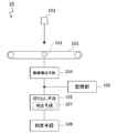
図2は、検査部10の構成の一例を示している。この例では、電磁波としてX線を検査対象物に照射することにより得られたX線透過画像を検査に供する画像として取得する。検査部10は、搬送部101、電磁波照射部102、電磁波検出部103、画像構成手段104、記憶部105、切り出し手段106及び判定手段108を備える。
FIG. 2 shows an example of the configuration of the inspection unit 10. In this example, an X-ray transmission image obtained by irradiating an inspection object with X-rays as an electromagnetic wave is acquired as an image to be subjected to inspection. The inspection unit 10 includes a transport unit 101, an electromagnetic wave irradiation unit 102, an electromagnetic wave detection unit 103, an image forming unit 104, a storage unit 105, a cutting unit 106, and a determination unit 108.
搬送部101は、1または複数のベルトコンベアで構成され、画像を撮影する検査領域まで検査対象物を搬送し、撮影後、検査領域から排出させる。
The transport unit 101 is composed of one or a plurality of belt conveyors, transports the inspection object to the inspection area where the image is taken, and discharges the inspection object from the inspection area after taking the picture.
電磁波照射部102は、画像を撮影するのに必要な電磁波(例えば、X線、紫外線、可視光、赤外線等)を、検査領域に照射する。電磁波照射部102は、例えば搬送部101において検査対象物が載置される搬送面に、垂直に電磁波を照射するように配置される。検査領域は、電磁波照射部102から照射される電磁波が外部に漏れるのを防ぐべく、必要に応じて遮蔽カバーで覆われる。
The electromagnetic wave irradiation unit 102 irradiates the inspection area with electromagnetic waves (for example, X-rays, ultraviolet rays, visible light, infrared rays, etc.) necessary for taking an image. The electromagnetic wave irradiation unit 102 is arranged so as to irradiate the electromagnetic wave vertically on the transport surface on which the inspection object is placed, for example, in the transport unit 101. The inspection area is covered with a shielding cover, if necessary, in order to prevent the electromagnetic waves emitted from the electromagnetic wave irradiation unit 102 from leaking to the outside.
電磁波検出部103は、搬送部101を挟んで電磁波照射部102と対向する位置に配置される。電磁波検出部103は、電磁波照射部102が照射した電磁波を検出可能な検出素子を複数備え、検査領域を通過して電磁波検出部103に到達する電磁波の強度の分布を検出する。電磁波検出部103は、例えば、ラインセンサ、エリアセンサ、TDI(Time Delay Integration)センサ等とするとよい。
The electromagnetic wave detection unit 103 is arranged at a position facing the electromagnetic wave irradiation unit 102 with the transport unit 101 in between. The electromagnetic wave detection unit 103 includes a plurality of detection elements capable of detecting the electromagnetic wave irradiated by the electromagnetic wave irradiation unit 102, and detects the distribution of the intensity of the electromagnetic wave that passes through the inspection region and reaches the electromagnetic wave detection unit 103. The electromagnetic wave detection unit 103 may be, for example, a line sensor, an area sensor, a TDI (Time Delay Integration) sensor, or the like.
電磁波照射部102と電磁波検出部103の間の検査領域に検査対象物が存在すると、電磁波照射部102から照射された電磁波は検査対象物の各位置における当該電磁波の透過率に応じて減衰して電磁波検出部103に到達することになり、検査対象物の内部の状態が電磁波検出部103によって検出される電磁波の強度の分布として観測される。
When an inspection object exists in the inspection area between the electromagnetic wave irradiation unit 102 and the electromagnetic wave detection unit 103, the electromagnetic wave emitted from the electromagnetic wave irradiation unit 102 is attenuated according to the transmittance of the electromagnetic wave at each position of the inspection object. It reaches the electromagnetic wave detection unit 103, and the internal state of the inspection object is observed as the distribution of the intensity of the electromagnetic wave detected by the electromagnetic wave detection unit 103.
画像構成手段104は、電磁波検出部103で検出された検査対象物を透過した電磁波の強度の分布を2次元の画像として構成する。
The image forming means 104 configures the distribution of the intensity of the electromagnetic wave transmitted through the inspection object detected by the electromagnetic wave detecting unit 103 as a two-dimensional image.
記憶部105は、画像構成手段104において構成された検査対象物が写る画像のデータを格納する。記憶部105は、RAM、ハードディスク等の記憶装置により構成される。
The storage unit 105 stores the data of the image in which the inspection target object configured by the image forming means 104 is captured. The storage unit 105 is composed of a storage device such as a RAM and a hard disk.
切り出し手段106は、画像構成手段104が構成した検査対象物が写る画像を記憶部105から読み出し、当該画像において検査対象物の検査範囲を所定の方法により特定して、特定された検査範囲を当該画像から切り出し、判定対象画像として判定手段108に出力する。また、切り出し手段106において検査対象物の画像から切り出された検査範囲の画像から、更により小さい部分画像を抽出し、これを判定対象画像として判定手段108に出力する抽出手段107を更に備えてもよい。
The cutting means 106 reads out an image of the inspection object configured by the image forming means 104 from the storage unit 105, specifies the inspection range of the inspection object in the image by a predetermined method, and sets the specified inspection range. It is cut out from the image and output to the determination means 108 as a determination target image. Further, the extraction means 107 that extracts a smaller partial image from the image of the inspection range cut out from the image of the inspection target by the cutting means 106 and outputs the smaller partial image to the determination means 108 as the determination target image may be further provided. good.
切り出し手段106において切り出し、又は抽出手段107において抽出する判定対象画像のサイズ及び形状は、判定手段108における判定において採用する学習済みモデルの生成に用いた学習対象画像と同じサイズ及び形状とする。
The size and shape of the determination target image cut out by the cutting means 106 or extracted by the extraction means 107 shall be the same size and shape as the learning target image used for generating the learned model adopted in the determination by the determination means 108.
切り出し手段106における、検査対象物の検査範囲を特定する具体的な方法、及び抽出手段107における、更により小さい部分画像を抽出する具体的な方法は、後述する教師データ生成部12の切り出し手段121及び抽出手段122における特定方法及び抽出方法と同じであるため、ここでの説明は省略する。
The specific method of specifying the inspection range of the inspection object in the cutting means 106 and the specific method of extracting a smaller partial image in the extracting means 107 are the cutting means 121 of the teacher data generation unit 12 described later. Since it is the same as the specific method and the extraction method in the extraction means 122, the description here is omitted.
判定手段108は、切り出し手段106から出力された判定対象画像を機械学習実行部13において予め生成された学習済みモデルに入力し、出力された判定結果に基づき検査対象物が正常であるか否かの検査(除去対象物であるか否かの判定)を行う。判定手段108における具体的な検査方法は、後述の検査装置1の検査モードの動作の説明の中で例示する。
The determination means 108 inputs the determination target image output from the cutting means 106 into the trained model generated in advance by the machine learning execution unit 13, and based on the output determination result, whether or not the inspection object is normal. (Determining whether or not the object is to be removed). A specific inspection method in the determination means 108 will be illustrated in the description of the operation of the inspection mode of the inspection device 1 described later.
なお、以上説明した検査部10のうち、画像構成手段104、切り出し手段106、抽出手段107及び判定手段108は、後述する制御部11の一部として構成されてもよい。
Of the inspection units 10 described above, the image forming means 104, the cutting means 106, the extracting means 107, and the determining means 108 may be configured as a part of the control unit 11 described later.
ディスプレイ14は、液晶ディスプレイ等の表示装置であり、検査装置1の操作画面や各種画像を表示する。操作インタフェース15は、スイッチ、マウス、キーボード等の入力手段であり、ユーザによる検査装置1の操作入力を受け付ける。
The display 14 is a display device such as a liquid crystal display, and displays an operation screen of the inspection device 1 and various images. The operation interface 15 is an input means such as a switch, a mouse, and a keyboard, and receives an operation input of the inspection device 1 by a user.
制御部11は検査装置1の各構成要素の制御を行う。制御部11は、例えばCPU、記憶素子等により構成されるコンピュータにより構成される。制御部11は、教師データ生成部12と機械学習実行部13とを含んでいる。教師データ生成部12は本発明の教師データ生成装置に相当する。
The control unit 11 controls each component of the inspection device 1. The control unit 11 is composed of, for example, a computer composed of a CPU, a storage element, and the like. The control unit 11 includes a teacher data generation unit 12 and a machine learning execution unit 13. The teacher data generation unit 12 corresponds to the teacher data generation device of the present invention.
教師データ生成部12は、検査装置1の学習モードにおいて、機械学習実行部13にて実施される機械学習に用いられる教師データを生成する。図3は、教師データ生成部12の構成を示すブロック図である。図3に示すように、教師データ生成部12は、切り出し手段121、表示制御手段123、振分処理手段124、及び教師データ記憶部125を備える。
The teacher data generation unit 12 generates teacher data used for machine learning performed by the machine learning execution unit 13 in the learning mode of the inspection device 1. FIG. 3 is a block diagram showing the configuration of the teacher data generation unit 12. As shown in FIG. 3, the teacher data generation unit 12 includes a cutting unit 121, a display control unit 123, a distribution processing unit 124, and a teacher data storage unit 125.
切り出し手段121は、検査対象物が写る画像の入力を受け付け、当該画像において検査対象物の検査範囲を所定の方法により特定し、特定された検査範囲を当該画像から切り出す。
The cutting means 121 accepts the input of an image showing the inspection target, specifies the inspection range of the inspection target in the image by a predetermined method, and cuts out the specified inspection range from the image.
検査対象物が写る画像における、検査対象物の検査範囲の特定方法は任意であり、例えば、基準点に基づく特定方法やブロブ解析による特定方法が挙げられる。
The method of specifying the inspection range of the inspection target in the image showing the inspection target is arbitrary, and examples thereof include a identification method based on a reference point and a identification method by blob analysis.
基準点に基づく特定方法では、例えば、オペレータが入力した1以上の基準点の位置情報及び基準点からの距離を示す情報に基づき検査範囲を特定する。基準点の位置情報の入力方法は任意である。例えば、オペレータがディスプレイ14に表示された検査対象物が写る画像を見ながら、設定したい位置を操作インタフェース15から入力してもよい。
In the identification method based on the reference point, for example, the inspection range is specified based on the position information of one or more reference points input by the operator and the information indicating the distance from the reference point. The method of inputting the position information of the reference point is arbitrary. For example, the operator may input the position to be set from the operation interface 15 while looking at the image of the inspection object displayed on the display 14.
設定する基準点の個数は任意であるが、検査範囲の各角に設定することで、もし画像ごとに検査対象物2の体勢が異なっていても検査範囲を確実に特定することができる。例えば、四角形の検査範囲であれば、基準点を4つ設定することで検査範囲を確実に特定することができる。
The number of reference points to be set is arbitrary, but by setting each corner of the inspection range, the inspection range can be reliably specified even if the posture of the inspection object 2 is different for each image. For example, in the case of a quadrangular inspection range, the inspection range can be reliably specified by setting four reference points.
もっとも、例えば次のようなケースでは基準点を1個設定すれば足りる。一般に、検査部10による複数の検査対象物2の画像の撮影に際しては、検査対象物2は予め設定した概ね同じ体勢で搬送部101に順次載置、搬送され撮影される。そこで、例えば図4(a)に示す収納部2pとその上下にそれぞれ設けられるシール部2s(一辺の長さw、他辺の長さdの長方形)とを備える検査対象物2について、搬送方向がX方向の場合、検査対象物2のシール部2sの長手方向がX方向、短手方向がX方向に直交するY方向となるように、検査対象物2を搬送部101に載置するようにする。加えて検査範囲を、基準点を起点に一辺がX方向に長さa(>w)で延伸され、他辺がY方向に長さb(>d)で延伸された長方形の範囲と定義する。長さa、bは、固定値として予め設定しておいてもよいし、操作インタフェース15からのオペレータの入力により任意に設定可能に構成してもよい。これにより、上側のシール部2sを検査範囲としたい場合、基準点Bをシール部2sの左上角付近に設定することで、図4(b)に示すように検査範囲Aを特定することができる。
However, in the following cases, for example, it is sufficient to set one reference point. Generally, when the inspection unit 10 takes an image of a plurality of inspection objects 2, the inspection object 2 is sequentially placed on the conveying unit 101 in a substantially the same posture set in advance, and is conveyed and photographed. Therefore, for example, with respect to the inspection object 2 including the storage portion 2p shown in FIG. 4A and the seal portions 2s (rectangles having a length w on one side and a length d on the other side) provided above and below the storage portion 2p, the transport direction. Is in the X direction, the inspection object 2 is placed on the transport unit 101 so that the longitudinal direction of the seal portion 2s of the inspection object 2 is the X direction and the lateral direction is the Y direction orthogonal to the X direction. To. In addition, the inspection range is defined as a rectangular range in which one side is extended in the X direction by a length a (> w) and the other side is extended in the Y direction by a length b (> d) starting from the reference point. .. The lengths a and b may be set in advance as fixed values, or may be arbitrarily set by input from the operator from the operation interface 15. As a result, when it is desired to set the upper seal portion 2s as the inspection range, the inspection range A can be specified as shown in FIG. 4B by setting the reference point B near the upper left corner of the seal portion 2s. ..
ブロブ解析による特定方法では、画像の明暗に基づき画像を二値化することで、検査対象物の存在位置や形状などをブロブとして検出できることを利用して特定する。具体的には、検査対象物を透過した電磁波の強度に基づき画像を生成すると、検査対象物の存在部分と比べ、その周囲が非常に明るくなるため、この明暗に基づき検査対象物の存在位置や形状などをブロブとして検出することができる。そして、検査対象物のどの部分を検査範囲とするかは予めわかっているため、両者の照合により、検査対象物が写る画像における、検査対象物の検査範囲を特定することができる。
In the identification method by blob analysis, the image is binarized based on the brightness and darkness of the image, and the existence position and shape of the inspection object can be detected as a blob. Specifically, when an image is generated based on the intensity of the electromagnetic wave transmitted through the inspection object, the surrounding area becomes much brighter than the existing part of the inspection object. The shape and the like can be detected as a blob. Since it is known in advance which part of the inspection target is to be inspected, it is possible to specify the inspection range of the inspection target in the image in which the inspection target is captured by collating the two.
より具体的には、例えば、図5(a)に示す収納部2pとその上下にそれぞれ設けられるシール部2sとを備える検査対象物2について、上下いずれか又は双方のシール部2sを検査範囲として特定したい場合、まず、検査対象物2への電磁波照射により生成された、検査対象物2が写る画像を、検査対象物2の存在部分に相当する画像の暗さを閾値として二値化すると、図5(b)に示すようなブロブCとして検査対象物2の存在位置及び形状を検出することができる。そして、検査対象物2において、検査範囲とするシール部2sの存在位置は図5(a)に示すように予めわかっているため、これを画像における存在位置が特定された検査対象物2と照合することで、検査対象物2が写る画像における、シール部2sの存在位置(例えば上端及び下端のそれぞれから所定の距離の範囲)を、図5(c)に示すように検査範囲Aとして特定できる。
More specifically, for example, with respect to the inspection object 2 including the storage portion 2p shown in FIG. 5A and the seal portions 2s provided above and below the storage portion 2p, one or both of the upper and lower seal portions 2s are set as the inspection range. When it is desired to specify, first, the image in which the inspection object 2 is captured, which is generated by irradiating the inspection object 2 with an electromagnetic wave, is binarized with the darkness of the image corresponding to the existing portion of the inspection object 2 as a threshold value. The existing position and shape of the inspection object 2 can be detected as the blob C as shown in FIG. 5 (b). Then, in the inspection object 2, the existence position of the seal portion 2s to be inspected is known in advance as shown in FIG. 5 (a), so this is collated with the inspection object 2 whose existence position in the image is specified. By doing so, the existing position of the seal portion 2s (for example, a range of predetermined distances from each of the upper end and the lower end) in the image in which the inspection object 2 is captured can be specified as the inspection range A as shown in FIG. 5 (c). ..
また、例えば、収納部2pに柄や模様がある一方、シール部2sは透明である検査対象物2の場合には、シール部2sを含む検査対象物2の存在部分に相当する画像の暗さを閾値として検査対象物2が写る画像を二値化して、図6(a)に示すようなブロブCとして検査対象物2の存在位置及び形状を検出するとともに、収納部2pの存在部分に相当する画像の暗さを閾値として検査対象物2が写る画像を二値化して、収納部2pを示すブロブDを検出し、この2つのブロブの差分をとることで、上下それぞれのシール部2sの存在位置を、図6(c)に示すように検査範囲Aとして特定してもよい。
Further, for example, in the case of the inspection object 2 in which the storage portion 2p has a pattern or a pattern while the seal portion 2s is transparent, the darkness of the image corresponding to the existing portion of the inspection object 2 including the seal portion 2s. Is used as a threshold value, the image of the inspection object 2 is binarized, the position and shape of the inspection object 2 are detected as the blob C as shown in FIG. By binarizing the image in which the inspection object 2 appears with the darkness of the image to be inspected as a threshold value, detecting the blob D indicating the storage portion 2p, and taking the difference between these two blobs, the upper and lower seal portions 2s The existing position may be specified as the inspection range A as shown in FIG. 6 (c).
また、シール部2sの存在位置を特定した上で、更に、シール部2s内の異物の存在部分に相当する画像の暗さを閾値として検査対象物2が写る画像を二値化して、異物存在部分を示すブロブFを図7(a)に示すように検出し、このブロブFを含む所定の範囲を、図7(b)に示すように検査範囲Aとして特定してもよい。図7ではブロブFが1つの場合を例示したが、複数の場合でも複数の検査範囲Aを同様に特定可能である。
Further, after specifying the existence position of the seal portion 2s, the image showing the inspection object 2 is binarized with the darkness of the image corresponding to the existence portion of the foreign matter in the seal portion 2s as a threshold value, and the presence of the foreign matter is present. A blob F indicating a portion may be detected as shown in FIG. 7 (a), and a predetermined range including the blob F may be specified as an inspection range A as shown in FIG. 7 (b). Although the case where the blob F is one is illustrated in FIG. 7, a plurality of inspection ranges A can be similarly specified even in the case of a plurality of blobs F.
なお、ここで例示したブロブ解析による特定方法では、上記のとおり検査範囲Aを複数同時に特定することが可能であり、この場合、全てを検査範囲Aとして特定してもよいし、任意の一部を検査範囲Aとして特定してもよい。
In the blob analysis identification method illustrated here, it is possible to specify a plurality of inspection ranges A at the same time as described above. In this case, all of them may be specified as inspection ranges A, or any part of them may be specified. May be specified as the inspection range A.
切り出し手段121は、以上のように特定された検査範囲の画像を検査対象物2の画像から切り出し、学習対象画像として振分処理手段124に出力する。
The cutting means 121 cuts out an image of the inspection range specified as described above from the image of the inspection target 2, and outputs the image to the sorting processing means 124 as a learning target image.
切り出し手段121は、切り出された検査範囲Aの画像から、より小さい部分画像を抽出する抽出手段122を更に備えてもよい。図8(b)は、図8(a)に示すように特定された検査範囲Aを4分割したそれぞれの部分A1、A2、A3及びA4の画像を抽出する場合の例を示したものである。いくつに分割するかは、固定値として予め設定しておいてもよいし、操作インタフェース15からのオペレータの入力により任意に設定可能に構成してもよい。
The cutting means 121 may further include an extraction means 122 that extracts a smaller partial image from the cut out image of the inspection range A. FIG. 8B shows an example in which the images of the respective portions A1, A2, A3 and A4 obtained by dividing the inspection range A specified as shown in FIG. 8A into four are extracted. .. The number of divisions may be set in advance as a fixed value, or may be arbitrarily set by input from the operator from the operation interface 15.
抽出手段122は、このように抽出された部分画像を学習対象画像として振分処理手段124に出力する。
The extraction means 122 outputs the partial image thus extracted to the distribution processing means 124 as a learning target image.
このように検査範囲Aを細分化した部分画像を学習対象画像とすることで、細分化しない場合と比べ、多くの学習データを収集することができる。
By using the partial image in which the inspection range A is subdivided as the learning target image in this way, more learning data can be collected as compared with the case where the inspection range A is not subdivided.
抽出手段122は、部分画像の抽出に際し、隣接する部分画像と部分的に重複するように抽出してもよい。図8(c)は、図8(b)の場合と同じ抽出幅で、隣接する部分画像と4分の1ずつ重複するように抽出する例であり、この場合、5つの部分A1、A2、A3、A4及びA5のそれぞれについて部分画像を抽出することができる。どの程度重複させるかは、固定値として予め設定しておいてもよいし、操作インタフェース15からのオペレータの入力により任意に設定可能に構成してもよい。
When extracting the partial image, the extraction means 122 may extract so as to partially overlap the adjacent partial image. FIG. 8 (c) is an example in which the extraction width is the same as in the case of FIG. 8 (b) and the image is extracted so as to overlap the adjacent partial image by a quarter. Partial images can be extracted for each of A3, A4 and A5. The degree of duplication may be set in advance as a fixed value, or may be arbitrarily set by input from the operator from the operation interface 15.
このように、隣接する部分画像と部分的に重複するように部分画像を抽出することにより、部分画像を重複させない場合と比べ、より多くの学習データを収集することができる。また、部分画像を重複させない場合、各部分の境目において噛み込み等があったときの学習データが不完全なものになるが、重複させることでこのような事態を防ぐことができ、この観点からもより多くの学習データの収集に資する。
In this way, by extracting the partial image so as to partially overlap the adjacent partial image, more learning data can be collected as compared with the case where the partial image is not duplicated. In addition, if the partial images are not duplicated, the learning data when there is biting at the boundary of each part becomes incomplete, but by duplicating, such a situation can be prevented, and from this viewpoint. Also contributes to the collection of more learning data.
なお、検査範囲の画像に基づき生成された学習済みモデルに追加学習を施すに際して切り出し手段121が学習対象画像を切り出す場合には、当該学習済みモデルの生成に用いたサイズ及び形状の検査範囲の画像を切り出すように、切り出し手段121における切り出し条件を設定する。また、部分画像に基づき生成された学習済みモデルに追加学習を施すに際して抽出手段122が学習対象画像を切り出す場合には、当該部分画像に基づく学習済みモデルの生成に用いたサイズ及び形状の部分画像の抽出を行うように、抽出手段122における抽出条件を設定する。
When the cutting means 121 cuts out the image to be learned when performing additional learning on the trained model generated based on the image of the inspection range, the image of the inspection range of the size and shape used to generate the trained model. The cutting condition in the cutting means 121 is set so as to cut out. Further, when the extraction means 122 cuts out the learning target image when performing additional learning on the trained model generated based on the partial image, the partial image of the size and shape used for generating the trained model based on the partial image. The extraction condition in the extraction means 122 is set so as to perform the extraction.
表示制御手段123は、ディスプレイでの表示を制御する。表示制御手段123は、切り出し手段121により切り出された又は抽出手段122により抽出された学習対象画像を、ディスプレイ14に選択可能に表示させる。図9は、学習対象画像をディスプレイ14に表示する際の学習対象表示画面の表示例を示している。学習対象表示画面は、入力画像表示領域R2、学習対象画像表示領域R1、情報表示領域R3を備えている。学習対象画像表示領域R1は、学習対象画像が並べて表示される領域である。学習対象画像表示領域R1には、学習対象画像のほか、各学習対象画像に対する合否の振り分けを行うためのユーザインタフェース等が表示される。入力画像表示領域R2は検査対象物の画像が表示される領域である。情報表示領域R3は、選択された学習対象画像に関する情報(例えば、画像ファイルの名称、格納場所等)が表示される領域である。
The display control means 123 controls the display on the display. The display control means 123 causes the display 14 to selectively display the learning target image cut out by the cutting means 121 or extracted by the extracting means 122. FIG. 9 shows a display example of the learning target display screen when displaying the learning target image on the display 14. The learning target display screen includes an input image display area R2, a learning target image display area R1, and an information display area R3. The learning target image display area R1 is an area in which the learning target images are displayed side by side. In the learning target image display area R1, in addition to the learning target image, a user interface for sorting pass / fail for each learning target image and the like are displayed. The input image display area R2 is an area in which an image of the inspection object is displayed. The information display area R3 is an area in which information related to the selected learning target image (for example, the name of the image file, the storage location, etc.) is displayed.
入力画像表示領域R2に検査対象物の画像を表示する際、抽出された学習対象画像に対応する領域を指し示す表示を重畳して表示してもよい。この学習対象画像に対応する領域を示す表示は、ユーザが表示/非表示を選択できるように構成してもよい。
When displaying the image of the inspection target object in the input image display area R2, the display indicating the area corresponding to the extracted learning target image may be superimposed and displayed. The display indicating the area corresponding to the learning target image may be configured so that the user can select display / non-display.
学習対象画像表示領域R1に学習対象画像を並べて表示する際、既存の学習済みモデルにて各学習対象画像の判定を行った場合の判定結果を示す数値(スコア)の順にソートして、学習対象画像を表示してもよい。
When the learning target images are displayed side by side in the learning target image display area R1, the learning target is sorted in the order of the numerical values (scores) indicating the judgment results when each learning target image is judged by the existing trained model. An image may be displayed.
また、学習対象画像表示領域R1に並べて表示する個々の学習対象画像に対し、判定結果を示す情報を視認可能に表示してもよい。具体的には、個々の学習対象画像に重畳または隣接する位置にスコアや判定結果(正常/非正常の別等)等を表示してもよい。また、個々の学習対象画像について、判定結果を示す表示上の演出をしてもよい。例えば、正常であるか非正常であるかに応じて、異なる色の枠で囲む等が挙げられる。
Further, the information indicating the determination result may be visually displayed for each learning target image displayed side by side in the learning target image display area R1. Specifically, a score, a determination result (normal / abnormal, etc.) may be displayed at a position superimposed on or adjacent to each learning target image. Further, for each learning target image, a display effect indicating a determination result may be produced. For example, it may be surrounded by frames of different colors depending on whether it is normal or abnormal.
学習対象画像表示領域R1に表示された学習対象画像の1つをクリックすることで、その学習対象画像を選択することができる。学習対象画像表示領域R1で学習対象画像を選択すると、学習対象画像表示領域R1においては選択された学習対象画像が枠で囲まれて表示され、入力画像表示領域R2においては、選択された学習対象画像に対応する検査範囲又は部分領域が、他とは区別できるよう(例えば、二重の枠で囲まれて)に表示される。
By clicking one of the learning target images displayed in the learning target image display area R1, the learning target image can be selected. When a learning target image is selected in the learning target image display area R1, the selected learning target image is displayed surrounded by a frame in the learning target image display area R1, and the selected learning target is displayed in the input image display area R2. The inspection area or subregion corresponding to the image is displayed so that it can be distinguished from the others (eg, surrounded by a double frame).
上記とは反対に、入力画像表示領域R2に表示された学習対象画像に対応する検査範囲又は部分領域の1つをクリックすることで、当該検査範囲又は部分領域に対応する学習対象画像を選択することができる。このようにして入力画像表示領域R2をクリックすると、学習対象画像表示領域R1においては選択された検査範囲又は部分領域に対応する学習対象画像が枠で囲まれて表示され、入力画像表示領域R2においては、選択された検査範囲又は部分領域が、他とは区別できるよう(例えば、二重の枠で囲まれて)に表示される。このような検査対象物の画像と選択した学習対象画像とを対応付けた表示を行うことにより、選択した学習対象画像が検査対象物の画像においてどのように映っているのかを一見して把握することが可能になる。
Contrary to the above, by clicking one of the inspection range or partial area corresponding to the learning target image displayed in the input image display area R2, the learning target image corresponding to the inspection range or partial area is selected. be able to. When the input image display area R2 is clicked in this way, the learning target image corresponding to the selected inspection range or partial area is displayed in the learning target image display area R1 surrounded by a frame, and in the input image display area R2. Is displayed so that the selected inspection range or subregion can be distinguished from others (eg, surrounded by a double frame). By displaying the image of the inspection target and the selected learning target image in association with each other, it is possible to grasp at a glance how the selected learning target image is reflected in the image of the inspection target. Will be possible.
また、学習対象画像が選択されると、入力画像表示領域R2において、選択された学習対象画像に対応する部分を拡大して表示してもよい。このようにすれば、着目した学習対象画像に対応する部分を、容易に詳しく確認することができる。また、選択された学習対象画像について、情報表示領域R3において、スコアや判定結果(正常/非正常の別等)等を表示してもよい。
Further, when the learning target image is selected, the portion corresponding to the selected learning target image may be enlarged and displayed in the input image display area R2. In this way, the part corresponding to the learning target image of interest can be easily confirmed in detail. Further, for the selected learning target image, a score, a determination result (normal / abnormal, etc.) and the like may be displayed in the information display area R3.
振分処理手段124は、抽出された学習対象画像について、正常であるか非正常であるかなど、所定のいずれかの分類にユーザが目視に基づいて振り分ける。
The sorting processing means 124 visually sorts the extracted learning target image into any predetermined classification such as whether it is normal or abnormal.
ユーザにより学習対象画像を所定のいずれかの分類に振り分ける操作が行われると、振分処理手段124はその操作に応じて当該学習対象画像をいずれかの分類に振り分け、学習対象画像と振り分けられた分類とが対応付けられた教師データとして教師データ記憶部125に記憶させる。
When the user performs an operation of sorting the learning target image into one of the predetermined classifications, the sorting processing means 124 sorts the learning target image into one of the classifications according to the operation and sorts the learning target image from the learning target image. It is stored in the teacher data storage unit 125 as teacher data associated with the classification.
学習対象画像を所定のいずれかの分類に振り分ける操作とは、例えば正常であるか非正常であるかを振り分ける場合には、ユーザがディスプレイ14を見ながら操作インタフェース15を操作して学習対象画像を選択し、選択中の学習対象画像が正常であるか非正常であるかをユーザが目視して判定し、正常である場合にはOKボタンをクリックし、非正常である場合にはNGボタンをクリックするといった操作である。なお、ユーザが操作して学習対象画像を選択するのではなく、振分処理手段124により自動的に決定された順番に従って複数の学習対象画像について順次振り分ける操作を行うように構成してもよい。
The operation of allocating the learning target image to any of the predetermined classifications is, for example, in the case of allocating whether the learning target image is normal or abnormal, the user operates the operation interface 15 while looking at the display 14 to sort the learning target image. The user visually determines whether the selected image to be learned is normal or abnormal, clicks the OK button if it is normal, and clicks the NG button if it is abnormal. It is an operation such as clicking. In addition, instead of the user operating to select the learning target image, the operation may be configured to sequentially sort the plurality of learning target images according to the order automatically determined by the sorting processing means 124.
学習対象画像の分類の仕方は、単に、内容物の噛み込み、シールの皺、シールの折れ等のいずれか1つの判定項目について正常であるか非正常であるかの2つの分類に分ける仕方のほか、例えば、内容物の噛み込み、シールの皺、シールの折れ等の複数の判定項目についてそれぞれ正常であるか否かをユーザが目視して判定し、それぞれが複数の判定項目の判定結果の組み合わせからなる、複数の分類に分ける仕方を採用してもよい。例えば、判定項目が3つであれば、それぞれの項目について正常又は非正常の2通りがあるため、2の3乗である8つの分類のいずれかに振り分ける。このように分類しておくことで、学習対象画像が非正常である場合について各判定項目の正常非正常の組み合わせごとに分類可能な学習済みモデルの生成やその追加学習に用いることができる。
The method of classifying the images to be learned is simply divided into two classifications of normal or abnormal for any one of the judgment items such as biting of the contents, wrinkles of the seal, and breakage of the seal. In addition, for example, the user visually determines whether or not each of a plurality of judgment items such as biting of the contents, wrinkles of the seal, and breakage of the seal is normal, and each of the judgment results of the plurality of judgment items is determined. A method of dividing into a plurality of classifications consisting of combinations may be adopted. For example, if there are three determination items, there are two types of normal and abnormal for each item, so the items are classified into one of eight categories, which is 2 to the 3rd power. By classifying in this way, it is possible to generate a trained model that can be classified according to the combination of normal and abnormal of each determination item when the image to be learned is abnormal, and to use it for additional learning.
また、それぞれの学習対象画像について、複数の判定項目についてそれぞれ正常であるか否かをユーザが目視して判定し、判定項目ごとに正常である非正常であるか2つの分類に分ける仕方を採用してもよい。すなわち、1つの学習対象画像をいずれか1つの分類に振り分けるのではなく、判定項目ごとに正常又は非正常のいずれかに分類する。このように分類しておくことで、それぞれの判定項目個別に正常非正常を判定可能な学習済みモデルの生成やそれらの追加学習などに用いることができる。
In addition, for each learning target image, the user visually judges whether or not each of a plurality of judgment items is normal, and adopts a method of classifying each judgment item into two categories, normal or abnormal. You may. That is, instead of allocating one learning target image to any one classification, it is classified into either normal or abnormal for each determination item. By classifying in this way, it can be used for generation of trained models capable of judging normality / non-normality for each judgment item individually and for additional learning of them.
振分処理手段124において、いかなる分類の仕方を選択するかは、ここでの分類の仕方が、学習対象画像に基づき機械学習実行部13で生成される学習済みモデルが判定対象画像の入力に対して出力する判定結果(分類結果)に反映されるため、いかなる判定結果を求めるかに依存する。また、既に生成された学習済みモデルに追加学習をする場合には、当該学習済みモデルがいかなる分類で判定結果を出力するように生成されているかに依存する。
As for the classification method to be selected in the distribution processing means 124, the classification method here is that the trained model generated by the machine learning execution unit 13 based on the learning target image receives the input of the determination target image. Since it is reflected in the judgment result (classification result) output, it depends on what judgment result is required. Further, when additional learning is performed on the already generated trained model, it depends on what classification the trained model is generated to output the determination result.
教師データ記憶部125には、学習対象画像を振分処理手段124で振り分けられた分類と対応付けたものを教師データとして記憶する。なお、教師データ記憶部125には、外部装置で生成された教師データを記憶させてもよい。
In the teacher data storage unit 125, the image to be learned is stored as teacher data in association with the classification sorted by the sorting processing means 124. The teacher data storage unit 125 may store teacher data generated by an external device.
教師データ記憶部125は、RAM、ハードディスク等の記憶装置により構成される。教師データ記憶部125は、検査部10における記憶部105を兼用してもよい。また、検査装置1が各種情報を記憶するために備える記憶媒体を共用する形で用いてもよい。
The teacher data storage unit 125 is composed of a storage device such as a RAM and a hard disk. The teacher data storage unit 125 may also serve as the storage unit 105 in the inspection unit 10. Further, the inspection device 1 may be used in a form of sharing a storage medium provided for storing various information.
教師データ記憶部125に、学習対象画像を振分処理手段124で振り分けられた分類と対応付けたものを教師データとして記憶させる方法は、それぞれの学習対象画像が、正常であるか非正常であるか、複数の判定項目の判定結果のいずれの組み合わせであるか等、いずれの分類に振り分けられたかが識別可能に記憶されていればいかなる方法であってもよい。例えば、それぞれの学習対象画像を、振り分けられた分類ごとに用意されたフォルダに分けて記憶させてもよい。あるいは、振り分けられた分類を示す情報を、学習対象画像のファイル名や付加情報としてファイルに埋め込んでもよい。
In the method of storing the learning target image in the teacher data storage unit 125 as the teacher data in association with the classification sorted by the sorting processing means 124, each learning target image is normal or abnormal. Any method may be used as long as it is identifiable and memorable which classification is assigned, such as which combination of the judgment results of the plurality of judgment items. For example, each learning target image may be stored in a folder prepared for each sorted classification. Alternatively, the information indicating the sorted classification may be embedded in the file as the file name or additional information of the image to be learned.
教師データ記憶部125には、更に、教師データを構成する学習対象画像の、切り出し手段121及び抽出手段122における切り出し条件及び抽出条件を、教師データに関連付けて記録してもよい。
The teacher data storage unit 125 may further record the cutting conditions and the extraction conditions of the learning target image constituting the teacher data in the cutting means 121 and the extracting means 122 in association with the teacher data.
機械学習実行部13は、学習用プログラムを実行することにより、教師データ記憶部125から読み出した教師データ、すなわち分類の情報が付された学習対象画像を用いて、既存の学習済みモデルに対して追加的に機械学習を施して新たな学習済みモデルを生成する。または、教師データ記憶部125から読み出した教師データを用いて新規に機械学習を行い、新たな学習済みモデルを生成する。新規に学習済みモデルを生成する場合には、予め準備した初期の(未学習の)モデルに対して機械学習を行ってもよい。
By executing the learning program, the machine learning execution unit 13 uses the teacher data read from the teacher data storage unit 125, that is, the learning target image to which the classification information is attached, with respect to the existing trained model. Additional machine learning is applied to generate a new trained model. Alternatively, machine learning is newly performed using the teacher data read from the teacher data storage unit 125, and a new trained model is generated. When a new trained model is generated, machine learning may be performed on an initial (unlearned) model prepared in advance.
ここでいう機械学習とは、初期のモデル又は既に一定の学習が施されたモデルに対して、所定のデータの入力により繰り返し処理を行い、目標となる学習済みモデルに近づけることを意味する。具体的には例えば、ニューラルネットワークモデルに教師データを入力することで、正解が出力されるように重みやバイアスなどのパラメータを調整することを内容とする。
Machine learning here means that an initial model or a model that has already been trained to a certain extent is repeatedly processed by inputting predetermined data to bring it closer to the target trained model. Specifically, for example, by inputting teacher data into the neural network model, parameters such as weights and biases are adjusted so that the correct answer is output.
また、本発明でいう学習済みモデルとは、検査対象物の検査範囲の画像や部分画像の入力により、所定の判定結果、例えば正常性を示すスコア(数値等)、より具体的には例えば、非正常である可能性を示すスコアを出力するように学習されたモデルである。
Further, the learned model referred to in the present invention is a predetermined determination result, for example, a score (numerical value, etc.) indicating normality, more specifically, for example, by inputting an image or a partial image of an inspection range of an inspection object. It is a model trained to output a score indicating the possibility of being abnormal.
機械学習実行部13における機械学習の具体的な手法は任意であり、例えば、畳み込みニューラルネットワークモデルを用いた深層学習方法を採用してもよい。
The specific method of machine learning in the machine learning execution unit 13 is arbitrary, and for example, a deep learning method using a convolutional neural network model may be adopted.
続いて、以上のように構成される検査装置1の動作を、学習モードと検査モードのそれぞれについて説明する。
Next, the operation of the inspection device 1 configured as described above will be described for each of the learning mode and the inspection mode.
〔学習モードにおける動作〕
図10は、学習モードでの検査装置1の動作の手順を示すフローチャートである。学習モードは、検査装置1の操作インタフェース15にて学習モードを選択することにより開始される。学習モードが開始されると、ディスプレイ14に学習モード用の操作画面が表示される。ユーザは、この学習モード用の操作画面を以下の手順で操作することによって、教師データの生成及び、学習済みモデルに対する機械学習を行うことができる。 [Operation in learning mode]
FIG. 10 is a flowchart showing the operation procedure of theinspection device 1 in the learning mode. The learning mode is started by selecting the learning mode on the operation interface 15 of the inspection device 1. When the learning mode is started, the operation screen for the learning mode is displayed on the display 14. The user can generate teacher data and perform machine learning on the trained model by operating the operation screen for this learning mode according to the following procedure.
図10は、学習モードでの検査装置1の動作の手順を示すフローチャートである。学習モードは、検査装置1の操作インタフェース15にて学習モードを選択することにより開始される。学習モードが開始されると、ディスプレイ14に学習モード用の操作画面が表示される。ユーザは、この学習モード用の操作画面を以下の手順で操作することによって、教師データの生成及び、学習済みモデルに対する機械学習を行うことができる。 [Operation in learning mode]
FIG. 10 is a flowchart showing the operation procedure of the
はじめに、教師データ生成部12は、ユーザによる入力画像を選択する操作を受け付ける(ステップS100)。入力画像は、検査部10にて実際に撮影された検査対象物の画像でもよいし、学習用に別途準備された検査対象物の画像でもよい。続いて、教師データ生成部12は、ユーザによる学習済みモデルを選択する操作を受け付ける(ステップS110)。ここで選択される学習済みモデルは、後段の機械学習において追加の学習が行われる対象となる。なお、新規に学習済みモデルを生成する場合には、ステップS110を省略してもよい。
First, the teacher data generation unit 12 accepts an operation of selecting an input image by the user (step S100). The input image may be an image of the inspection object actually taken by the inspection unit 10 or an image of the inspection object separately prepared for learning. Subsequently, the teacher data generation unit 12 accepts an operation of selecting the trained model by the user (step S110). The trained model selected here is the target for additional learning in the subsequent machine learning. When a new trained model is generated, step S110 may be omitted.
続いて、教師データ生成部12は、切り出し手段121において検査対象物の画像に基準点を設定するとともに、基準点を起点とする検査範囲を特定する各辺の長さの入力を受け付け、受け付けた切り出し条件に基づき特定された検査範囲の画像の切り出しを実施する(ステップS120)。また、切り出された検査範囲の画像を分割して部分画像を抽出する場合には、抽出手段122において分割数及び重複の程度の入力を受け付け、受け付けた抽出条件に基づき各部分画像の抽出を実施する(ステップS121)。
Subsequently, the teacher data generation unit 12 sets a reference point on the image of the inspection object in the cutting means 121, and accepts and accepts the input of the length of each side that specifies the inspection range starting from the reference point. The image of the inspection range specified based on the cutting conditions is cut out (step S120). Further, when the image of the cut-out inspection range is divided and the partial image is extracted, the extraction means 122 accepts the input of the number of divisions and the degree of duplication, and extracts each partial image based on the accepted extraction conditions. (Step S121).
ステップS120、S121では、具体的には、操作画面に表示される項目に所望の値を入力することにより、切り出し条件及び抽出条件が設定される。条件の設定が確定されると、切り出し手段121及び抽出手段122は、設定内容に応じて検査範囲の画像の切り出し及び部分画像の抽出処理を実施する。処理の結果得られた学習対象画像である検査範囲の画像又は部分画像は、分類の振り分けがされていない学習対象画像用のフォルダに格納される。
Specifically, in steps S120 and S121, the cutout condition and the extraction condition are set by inputting a desired value in the item displayed on the operation screen. When the setting of the conditions is confirmed, the cutting means 121 and the extracting means 122 carry out the cutting of the image of the inspection range and the extraction process of the partial image according to the setting contents. The inspection range image or partial image, which is the learning target image obtained as a result of the processing, is stored in the learning target image folder in which the classification is not sorted.
続いて、教師データ生成部12は、振分処理手段124において、学習対象画像のそれぞれについて、いずれの分類に振り分けるかを選択する操作を受け付け、選択に基づき学習対象画像と判定結果とを対応付けて教師データとして教師データ記憶部125に記憶させる(ステップS130)。
Subsequently, the teacher data generation unit 12 accepts an operation in the sorting processing means 124 to select which classification the learning target image should be sorted into, and associates the learning target image with the determination result based on the selection. The teacher data is stored in the teacher data storage unit 125 as teacher data (step S130).
ステップS130に続いて、機械学習実行部13は、ステップS130で生成した教師データに基づく機械学習を実行する指示を受け付け、当該指示に応じて学習用プログラムを実行して学習済みモデルに対する機械学習を実施する(ステップS140)。このとき、機械学習実行部13は、既存の学習済みモデルに対して追加的に機械学習を実施するのか、新規に学習済みモデルを生成するのかをユーザに選択させるインタフェースを操作画面に表示する。既存の学習済みモデルに追加的に機械学習を実施する場合、ユーザに学習済みモデルを選択させるメニューを提示するとよい。なお、この段階での学習済みモデルの選択を省略し、ステップS110で選択した学習済みモデルに対して機械学習を実施するように構成してもよい。そして、ステップS140での機械学習を終了すると、学習モードでの一連の処理が完了となる。
Following step S130, the machine learning execution unit 13 receives an instruction to execute machine learning based on the teacher data generated in step S130, executes a learning program in response to the instruction, and performs machine learning on the trained model. It is carried out (step S140). At this time, the machine learning execution unit 13 displays an interface on the operation screen that allows the user to select whether to additionally perform machine learning on the existing trained model or to generate a newly trained model. When performing additional machine learning on an existing trained model, it is advisable to present a menu that allows the user to select the trained model. It should be noted that the selection of the trained model at this stage may be omitted, and machine learning may be performed on the trained model selected in step S110. Then, when the machine learning in step S140 is completed, a series of processes in the learning mode is completed.
〔検査モードにおける動作〕
図11は、検査モードでの検査装置1の動作の手順を示すフローチャートである。検査モードは、検査装置1の操作インタフェース15にて検査モードを選択することにより開始される。検査モードが開始されると、ディスプレイ14に検査モード用の操作画面が表示される。ユーザは、この検査モード用の操作画面を以下の手順で操作することによって、検査対象物の検査を行うことができる。 [Operation in inspection mode]
FIG. 11 is a flowchart showing the operation procedure of theinspection device 1 in the inspection mode. The inspection mode is started by selecting the inspection mode on the operation interface 15 of the inspection device 1. When the inspection mode is started, the operation screen for the inspection mode is displayed on the display 14. The user can inspect the inspection object by operating the operation screen for this inspection mode according to the following procedure.
図11は、検査モードでの検査装置1の動作の手順を示すフローチャートである。検査モードは、検査装置1の操作インタフェース15にて検査モードを選択することにより開始される。検査モードが開始されると、ディスプレイ14に検査モード用の操作画面が表示される。ユーザは、この検査モード用の操作画面を以下の手順で操作することによって、検査対象物の検査を行うことができる。 [Operation in inspection mode]
FIG. 11 is a flowchart showing the operation procedure of the
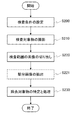
はじめに、検査装置1は、ユーザによる検査条件を設定する操作を受け付ける(ステップS200)。検査条件としては、画像撮影時のX線や可視光等の照射強度、露光時間、搬送速度等の一般的な検査装置の条件に加え、除去対象物の判定に用いる学習済みモデルの選択が含まれる。
First, the inspection device 1 accepts an operation of setting inspection conditions by the user (step S200). The inspection conditions include the selection of a learned model to be used for determining the object to be removed, in addition to the conditions of a general inspection device such as the irradiation intensity of X-rays and visible light at the time of image capture, the exposure time, and the transport speed. Is done.
検査条件の設定が完了すると、ユーザによる所定の操作に応じて、検査部10は検査対象物の検査を開始する。検査部10は、まず検査対象物を撮影位置まで搬送して撮影を行う(ステップS210)。
When the setting of the inspection conditions is completed, the inspection unit 10 starts the inspection of the inspection target according to the predetermined operation by the user. The inspection unit 10 first conveys the inspection object to the imaging position and performs imaging (step S210).
続いて検査部10は、切り出し手段106において、撮影された検査対象物の画像から検査範囲の画像を切り出し(ステップS220)又は抽出手段107において、切り出し手段106において切り出された検査範囲の画像から更に部分画像を抽出して(ステップS221)、判定対象画像を生成する。判定対象画像として切り出す検査範囲の画像の数及び抽出する部分画像の数はそれぞれ任意である。また、切り出し又は抽出する判定対象画像のサイズ及び形状は、判定に採用する学習済みモデルの生成に用いた学習対象画像と同じサイズ及び形状とする。
Subsequently, the inspection unit 10 cuts out an image of the inspection range from the image of the inspection object photographed by the cutting means 106 (step S220), or further cuts out an image of the inspection range cut out by the cutting means 106 in the extraction means 107. A partial image is extracted (step S221) to generate a determination target image. The number of images in the inspection range to be cut out as the judgment target image and the number of partial images to be extracted are arbitrary. Further, the size and shape of the judgment target image to be cut out or extracted shall be the same size and shape as the training target image used to generate the trained model used for the judgment.
続いて検査部10は、判定手段108において、切り出し手段106又は抽出手段107から出力された判定対象画像を学習済みモデルに入力し、出力された判定結果に基づき検査対象物が正常であるか否かの検査(除去対象物である否かの判定)を行う(ステップS230)。
Subsequently, the inspection unit 10 inputs the judgment target image output from the cutting means 106 or the extraction means 107 into the trained model in the judgment means 108, and whether or not the inspection target is normal based on the output judgment result. (Determining whether or not the object is to be removed) is performed (step S230).
判定手段108では、まず、判定対象画像が学習済みモデルに入力され、学習済みモデルは判定結果として、例えば正常性を示すスコア(数値等)を出力する。判定対象画像として切り出した検査範囲の画像及び抽出した部分画像が複数の場合には、それぞれの判定対象画像を学習済みモデルに入力して、それぞれの判定結果を得る。
In the determination means 108, first, the image to be determined is input to the trained model, and the trained model outputs, for example, a score (numerical value or the like) indicating normality as the determination result. When there are a plurality of images of the inspection range cut out and the extracted partial images as the judgment target images, each judgment target image is input to the trained model and each judgment result is obtained.
以下、学習済みモデルが数値を出力する場合を例にとって説明する。数値を出力する場合、出力する数値の範囲の設定は任意であり、例えば、0から1の範囲の数値を出力する。このとき、数値範囲における数値の刻みは任意であり、例えば0.01刻みであれば、0.12、0.81といった数値で出力する。出力された数値は、ディスプレイ14に表示させてもよいし、プリンタや記憶媒体など任意の出力手段に出力してもよい。
Below, the case where the trained model outputs a numerical value will be described as an example. When outputting a numerical value, the setting of the range of the numerical value to be output is arbitrary, and for example, the numerical value in the range of 0 to 1 is output. At this time, the step of the numerical value in the numerical range is arbitrary. For example, in the step of 0.01, the numerical value such as 0.12 or 0.81 is output. The output numerical value may be displayed on the display 14, or may be output to any output means such as a printer or a storage medium.
学習済みモデルを、2つの分類、例えば、正常又は非正常に分類された学習対象画像で学習させた場合には、当該学習済みモデルは、例えば、0を正常とし、非正常である可能性が高いほど1に近い数値を出力する。
When the trained model is trained with two classifications, for example, normal or abnormally classified training target images, the trained model may have, for example, 0 as normal and abnormal. The higher the value, the closer to 1 is output.
一方、学習済みモデルを、3つ以上の分類、例えば、正常及び複数の非正常ケースに分類された学習対象画像で学習させた場合には、当該学習済みモデルは、例えば、全分類の合計の数値を1として、可能性が高い分類ほど1に対する比の値が大きくなるように各分類の数値を出力する。例えば、分類1が0.2、分類2が0.4、分類3が0.3、分類4が0.1であれば、分類2である可能性が最も高いことになる。
On the other hand, when the trained model is trained with the training target images classified into three or more classifications, for example, normal and a plurality of abnormal cases, the trained model is, for example, the total of all classifications. The numerical value is set to 1, and the numerical value of each classification is output so that the value of the ratio to 1 becomes larger as the possibility of classification becomes larger. For example, if classification 1 is 0.2, classification 2 is 0.4, classification 3 is 0.3, and classification 4 is 0.1, the possibility of classification 2 is the highest.
続いて判定手段108は、学習済みモデルから出力された数値に基づき、検査対象物が除去対象物であるか否かの判定を行う。判定は、1つの判定対象画像のみを用いて行ってもよいし、複数の判定対象画像を用いて行ってもよい。
Subsequently, the determination means 108 determines whether or not the inspection target is the removal target based on the numerical value output from the trained model. The determination may be performed using only one determination target image, or may be performed using a plurality of determination target images.
まず、判定に用いる判定対象画像が1つである場合の判定例について説明する。
First, a judgment example when one judgment target image is used for judgment will be described.
分類が2つのとき、例えば、判定対象画像の入力に対し、0を正常とし、非正常である可能性が高いほど1に近い数値が出力されるときには、0から1の間の任意の値を閾値として、閾値以上のときに非正常であるとして除去対象物と判定する。
When there are two classifications, for example, 0 is set to normal for the input of the image to be judged, and when a numerical value closer to 1 is output as the possibility of being abnormal is higher, an arbitrary value between 0 and 1 is set. As a threshold value, when it is equal to or higher than the threshold value, it is judged to be an abnormal object to be removed.
一方、分類が3つ以上のとき、例えば、判定対象画像の入力に対し、全分類の合計の数値を1として、可能性が高い分類ほど1に対する比の値が大きくなるように各分類の数値が出力されるときには、複数の判定方法が考えられるが、任意の判定方法を採用してよい。例えば、分類1の数値が0.2、分類2の数値が0.4、分類3の数値が0.3、分類4の数値が0.1であり、かつ、分類2が正常を示す分類で、その他が非正常を示す分類であるとき、分類個別に見れば正常を示す分類2が最も可能性が高いため、これをもって非除去対象物であると判定する。もっとも、正常を示す分類と非正常を示す分類という観点では、正常を示す分類2の数値が0.4であるのに対し、非正常を示すその他の分類の数値の合計が0.6であるため、この観点からは非正常の可能性が高いことから、これをもって除去対象物であると判定する。
On the other hand, when there are three or more classifications, for example, for the input of the image to be judged, the total value of all classifications is set to 1, and the higher the possibility of classification, the larger the value of the ratio to 1 is. Is output, a plurality of determination methods can be considered, but any determination method may be adopted. For example, in a classification in which the numerical value of classification 1 is 0.2, the numerical value of classification 2 is 0.4, the numerical value of classification 3 is 0.3, the numerical value of classification 4 is 0.1, and the numerical value of classification 2 is normal. , Others are classifications indicating non-normality, and classification 2 indicating normality is most likely when viewed individually, so it is determined that this is a non-removal target. However, from the viewpoint of the classification indicating normality and the classification indicating abnormality, the numerical value of the classification 2 indicating normality is 0.4, while the total value of the other classifications indicating abnormality is 0.6. Therefore, from this point of view, there is a high possibility that it is abnormal, and it is determined that this is the object to be removed.
次に、判定に用いる判定対象画像が複数である場合の判定例について説明する。分類が2つのとき、例えば、判定対象画像の入力に対し、0を正常とし、非正常である可能性が高いほど1に近い数値が出力されるときには、まず、それぞれの判定対象画像について、0から1の間の任意の値を閾値として、閾値を境に正常又は非正常と判定する。そして、例えば、複数の判定対象画像のうち、所定の個数以上の非正常があれば、これをもって除去対象物であると判定する。このとき、すべての判定対象画像の正常/非正常の判定後に所定の個数との対比を行ってもよいし、非正常の判定対象画像の数をカウントしていき、所定の個数に到達した時点で除去対象物であると判定してもよい。また、正常又は非正常を判定する閾値よりも更に1に近い別の閾値である即決閾値を設け、ひとつでも即決閾値を超えた判定対象画像があれば、その時点で除去対象物であると判定してもよい。
Next, a judgment example when there are a plurality of judgment target images used for judgment will be described. When there are two classifications, for example, when 0 is set to normal for the input of the judgment target image and a numerical value closer to 1 is output as the possibility of being abnormal is higher, first, 0 is set for each judgment target image. Any value between 1 and 1 is used as a threshold value, and normal or abnormal is determined with the threshold value as a boundary. Then, for example, if there are a predetermined number or more of abnormalities among the plurality of images to be determined, it is determined that the image is to be removed. At this time, after the normal / abnormal determination of all the determination target images, a comparison with a predetermined number may be performed, or the number of abnormal determination target images is counted and when the predetermined number is reached. It may be determined that the object is to be removed. In addition, a prompt decision threshold value, which is another threshold value closer to 1 than the threshold value for determining normality or abnormality, is set, and if there is even one image to be determined that exceeds the prompt decision threshold value, it is determined that the image is to be removed at that time. You may.
一方、分類が3つ以上のとき、例えば、判定対象画像の入力に対し、全分類の合計の数値を1として、可能性が高い分類ほど1に対する比の値が大きくなるように各分類の数値が出力されるときには、まず、先に例示した判定対象画像が1つで分類が3つ以上の場合の非正常(除去対象物)の判定方法で、それぞれの判定対象画像の正常/非正常を判定した上で、先に例示した判定対象画像が複数で分類が2つの場合の除去対象物の判定方法で、除去対象物の判定を行うことができる。
On the other hand, when there are three or more classifications, for example, for the input of the image to be judged, the total value of all classifications is set to 1, and the higher the possibility of classification, the larger the value of the ratio to 1 is. Is output, first, the normality / non-normality of each judgment target image is determined by the judgment method of non-normality (removal target object) when the judgment target image illustrated above is one and the classification is three or more. After the determination, the removal target object can be determined by the method for determining the removal target object when there are a plurality of determination target images and the classification is two as exemplified above.
複数の判定対象画像を用いて除去対象物であるか否かの判定を行う場合、複数の判定対象画像の選び方は任意である。例えば、図5(b)に示すような検査対象物2の画像において、上側のシール部2sと下側のシール部2sのそれぞれについて特定された2つの検査範囲Aの画像を切り出し、これら2つの画像を判定対象画像として用いてもよい。また、上下の検査範囲Aを、更にそれぞれn分割(nは2以上の整数)して得られた合計2n個の部分画像を判定対象画像として用いてもよい。また、上下それぞれn分割した部分画像から、上下1つずつ抽出して、2つの部分画像を抽出し、当該2つの部分画像を判定対象画像として用いてもよい。
When determining whether or not it is a removal target image using a plurality of determination target images, the method of selecting a plurality of determination target images is arbitrary. For example, in the image of the inspection object 2 as shown in FIG. 5B, two images of the inspection range A specified for each of the upper seal portion 2s and the lower seal portion 2s are cut out, and these two images are cut out. An image may be used as a determination target image. Further, a total of 2n partial images obtained by further dividing the upper and lower inspection ranges A into n (n is an integer of 2 or more) may be used as the determination target image. Alternatively, the upper and lower partial images may be extracted one by one from the upper and lower n-divided partial images, two partial images may be extracted, and the two partial images may be used as the determination target image.
最後に、判定手段108は、以上の判定処理により除去対象物と判定された検査対象物に対して、必要な処理を行う。ここで、必要な処理とは、例えば、撮影した画像とともに除去対象物を示す図形(例えば枠)をディスプレイ14に表示する処理、除去対象物を除去する処理、除去対象物と正常品とを振り分ける処理等である。以上で1単位の検査対象物に対する検査が完了となる。なお、検査対象物が連続して検査装置1に送り込まれる場合、検査装置1は上記の一連の工程を繰り返すことで連続的に検査対象物の検査を実施する。
Finally, the determination means 108 performs necessary processing on the inspection target object determined to be the removal target object by the above determination process. Here, the necessary processing includes, for example, a process of displaying a figure (for example, a frame) indicating the object to be removed together with the captured image on the display 14, a process of removing the object to be removed, and a process of sorting the object to be removed and a normal product. Processing etc. This completes the inspection of one unit of the inspection object. When the inspection target is continuously sent to the inspection device 1, the inspection device 1 continuously inspects the inspection target by repeating the above series of steps.
以上のような構成により、検査装置1は、学習モードにおいて学習用プログラムに入力する教師データを素早く大量に生成することができ、生成した教師データを入力として機械学習することにより学習済みモデルを生成することができる。そして検査モードにおいては、学習モードで生成した学習済みモデルを用いて精度の高い検査を行うことが可能となる。
With the above configuration, the inspection device 1 can quickly generate a large amount of teacher data to be input to the learning program in the learning mode, and generates a trained model by machine learning using the generated teacher data as input. can do. Then, in the inspection mode, it is possible to perform a highly accurate inspection using the trained model generated in the learning mode.
〔実施形態の変形〕
なお、上記に本実施形態を説明したが、本発明はこれらの例に限定されるものではない。
例えば、上記実施形態では、教師データ生成部12及び機械学習実行部13は、検査装置1に内蔵されていたが、教師データ生成部12及び機械学習実行部13は、検査装置1に内蔵されずに個別の教師データ生成装置、あるいは学習済みモデル生成装置として提供されてもよい。例えば、上記の教師データ生成部12及び機械学習実行部13として機能させるコンピュータプログラムをコンピュータに実行させることにより教師データ生成部12及び機械学習実行部13を実現してもよい。 [Modification of Embodiment]
Although the present embodiment has been described above, the present invention is not limited to these examples.
For example, in the above embodiment, the teacherdata generation unit 12 and the machine learning execution unit 13 are built in the inspection device 1, but the teacher data generation unit 12 and the machine learning execution unit 13 are not built in the inspection device 1. It may be provided as an individual teacher data generator or a trained model generator. For example, the teacher data generation unit 12 and the machine learning execution unit 13 may be realized by causing the computer to execute a computer program that functions as the teacher data generation unit 12 and the machine learning execution unit 13.
なお、上記に本実施形態を説明したが、本発明はこれらの例に限定されるものではない。
例えば、上記実施形態では、教師データ生成部12及び機械学習実行部13は、検査装置1に内蔵されていたが、教師データ生成部12及び機械学習実行部13は、検査装置1に内蔵されずに個別の教師データ生成装置、あるいは学習済みモデル生成装置として提供されてもよい。例えば、上記の教師データ生成部12及び機械学習実行部13として機能させるコンピュータプログラムをコンピュータに実行させることにより教師データ生成部12及び機械学習実行部13を実現してもよい。 [Modification of Embodiment]
Although the present embodiment has been described above, the present invention is not limited to these examples.
For example, in the above embodiment, the teacher
また、前述の各実施形態に対して、当業者が適宜、構成要素の追加、削除、設計変更を行ったものや、各実施形態の特徴を適宜組み合わせたものも、本発明の要旨を備えている限り、本発明の範囲に含有される。
In addition, those skilled in the art appropriately adding, deleting, or changing the design of each of the above-described embodiments, and those in which the features of each embodiment are appropriately combined are also provided with the gist of the present invention. As long as it is, it is included in the scope of the present invention.
1 検査装置
2 検査対象物
2p 収納部
2s シール部
10 検査部
101 搬送部
102 電磁波照射部
103 電磁波検出部
104 画像構成手段
105 記憶部
108 判定手段
11 制御部
12 教師データ生成部
106、121 切り出し手段
107、122 抽出手段
123 表示制御手段
124 振分処理手段
125 教師データ記憶部
13 機械学習実行部
14 ディスプレイ
15 操作インタフェース
A 検査範囲
A1、A2、A3、A4、A5 部分
B 基準点
C、D、F ブロブ
R1 学習対象画像表示領域
R2 入力画像表示領域
R3 情報表示領域 1 Inspection device 2Inspection object 2p Storage unit 2s Seal unit 10 Inspection unit 101 Transport unit 102 Electromagnetic wave irradiation unit 103 Electromagnetic wave detection unit 104 Image configuration means 105 Storage unit 108 Judgment means 11 Control unit 12 Teacher data generation unit 106, 121 Cutting means 107, 122 Extraction means 123 Display control means 124 Sorting processing means 125 Teacher data storage unit 13 Machine learning execution unit 14 Display 15 Operation interface A Inspection range A1, A2, A3, A4, A5 Part B Reference points C, D, F Blob R1 Learning target image display area R2 Input image display area R3 Information display area
2 検査対象物
2p 収納部
2s シール部
10 検査部
101 搬送部
102 電磁波照射部
103 電磁波検出部
104 画像構成手段
105 記憶部
108 判定手段
11 制御部
12 教師データ生成部
106、121 切り出し手段
107、122 抽出手段
123 表示制御手段
124 振分処理手段
125 教師データ記憶部
13 機械学習実行部
14 ディスプレイ
15 操作インタフェース
A 検査範囲
A1、A2、A3、A4、A5 部分
B 基準点
C、D、F ブロブ
R1 学習対象画像表示領域
R2 入力画像表示領域
R3 情報表示領域 1 Inspection device 2
Claims (15)
- 機械学習に用いられる教師データを生成する教師データ生成装置であって、前記教師データを用いて前記機械学習により生成される学習済みモデルは、検査対象物が写る画像から切り出された判定対象画像を当該学習済みモデルに入力し、出力された判定結果に基づき前記検査対象物が正常であるか否かの検査を行う検査装置で用いられるものであり、
検査対象物が写る画像の入力を受け付け、前記画像において前記検査対象物の検査範囲を所定の方法により特定し、特定された前記検査範囲を前記画像から切り出す切り出し手段と、
前記切り出し手段において切り出された前記検査範囲の画像を学習対象画像として、正常と非正常のいずれかに振り分ける振分操作に基づき、前記学習対象画像と振り分けの結果とを対応付ける振分処理手段と、
前記学習対象画像と振り分けの結果とが対応付けられた教師データを記憶する教師データ記憶手段とを備える
ことを特徴とする教師データ生成装置。 A teacher data generator that generates teacher data used for machine learning, and a trained model generated by the machine learning using the teacher data is a judgment target image cut out from an image showing an inspection object. It is used in an inspection device that inspects whether or not the inspection object is normal based on the judgment result output by inputting to the trained model.
An image of an image to be inspected is received, an inspection range of the inspection object is specified by a predetermined method in the image, and the specified inspection range is cut out from the image.
A sorting processing means for associating the learning target image with the sorting result based on a sorting operation of sorting the image of the inspection range cut out by the cutting means as a learning target image to either normal or abnormal.
A teacher data generation device including a teacher data storage means for storing teacher data in which the image to be learned and the result of distribution are associated with each other. - 前記検査範囲を特定する前記所定の方法は、入力された1以上の基準点の位置情報及び基準点からの距離を示す情報に基づき特定する方法であることを特徴とする請求項1に記載の教師データ生成装置。 The predetermined method for specifying the inspection range is the method for specifying based on the input position information of one or more reference points and the information indicating the distance from the reference point, according to claim 1. Teacher data generator.
- 前記検査範囲を特定する前記所定の方法は、前記画像の明暗の所定の閾値に基づき画像を二値化し、二値化された画像から検出されたブロブに基づき特定する方法であることを特徴とする請求項1に記載の教師データ生成装置。 The predetermined method for specifying the inspection range is characterized in that the image is binarized based on a predetermined threshold value of the brightness and darkness of the image, and the image is specified based on the blob detected from the binarized image. The teacher data generation device according to claim 1.
- 前記切り出し手段において切り出された前記検査範囲の画像から、より小さい部分画像を抽出する抽出手段を更に備え、
前記振分処理手段は、前記部分画像を学習対象画像として、少なくとも正常と非正常のいずれかに振り分ける振分操作に基づき、前記部分画像と振り分けの結果とを対応付ける
ことを特徴とする請求項1から3のいずれか1項に記載の教師データ生成装置。 Further provided with an extraction means for extracting a smaller partial image from the image of the inspection range cut out by the cutting means.
Claim 1 is characterized in that the sorting processing means associates the partial image with the result of sorting based on a sorting operation in which the partial image is used as a learning target image and is sorted into at least either normal or abnormal. The teacher data generator according to any one of 3 to 3. - 前記抽出手段は、隣接する部分画像と部分的に重複するように複数の前記部分画像を抽出することを特徴とする請求項4に記載の教師データ生成装置。 The teacher data generation device according to claim 4, wherein the extraction means extracts a plurality of the partial images so as to partially overlap the adjacent partial images.
- ディスプレイと、前記ディスプレイによる表示を制御する表示制御手段とを更に備え、
前記表示制御手段は、前記ディスプレイの第1領域に複数の前記学習対象画像を並べて表示させるとともに、前記ディスプレイの第2領域に前記検査対象物の画像を、前記学習対象画像に対応する領域を指し示す表示を重畳しつつ表示させることを特徴とする、請求項1から5のいずれか1項に記載の教師データ生成装置。 A display and a display control means for controlling the display on the display are further provided.
The display control means displays a plurality of the learning target images side by side in the first region of the display, and points the image of the inspection target in the second region of the display to the region corresponding to the learning target image. The teacher data generation device according to any one of claims 1 to 5, wherein the display is displayed while being superimposed. - 前記表示制御手段は、前記ディスプレイの第1領域に表示された複数の前記学習対象画像のうちの1つが選択されると、前記ディスプレイの第2領域に表示された前記検査対象物の画像における当該選択された前記学習対象画像に対応する領域を指し示す表示をさせることを特徴とする、請求項6に記載の教師データ生成装置。 When one of the plurality of learning target images displayed in the first area of the display is selected, the display control means corresponds to the image of the inspection target displayed in the second area of the display. The teacher data generation device according to claim 6, wherein a display indicating a region corresponding to the selected image to be learned is displayed.
- 検査対象物を搬送し、検査領域を通過させる搬送部と、
電磁波を前記検査領域に照射する電磁波照射部と、
前記搬送部を挟んで前記電磁波照射部と対向する位置に配置され、前記検査領域を通過する前記検査対象物を透過した電磁波を検出する電磁波検出部と、
前記電磁波検出部で検出された電磁波の強度の分布を2次元の画像として構成する画像構成手段と、
前記画像構成手段において構成された前記検査対象物が写る画像において、前記検査対象物の検査範囲を所定の方法により特定し、特定された前記検査範囲を前記画像から切り出す切り出し手段と、
前記切り出し手段において切り出された前記検査範囲の画像を判定対象画像として学習済みモデルに入力して、出力された判定結果に基づき前記検査対象物が正常であるか否かの検査を行う判定手段と、
を備える検査装置。 A transport unit that transports the object to be inspected and passes it through the inspection area,
An electromagnetic wave irradiation unit that irradiates the inspection area with electromagnetic waves,
An electromagnetic wave detection unit that is arranged at a position facing the electromagnetic wave irradiation unit with the transport unit in between and detects an electromagnetic wave that has passed through the inspection object passing through the inspection area.
An image forming means for forming a distribution of the intensity of the electromagnetic wave detected by the electromagnetic wave detecting unit as a two-dimensional image, and an image forming means.
In an image showing the inspection object configured by the image forming means, an inspection range of the inspection object is specified by a predetermined method, and the specified inspection range is cut out from the image.
An image of the inspection range cut out by the cutting means is input to the trained model as a judgment target image, and a judgment means for inspecting whether or not the inspection target is normal based on the output judgment result is used. ,
Inspection device equipped with. - 前記検査範囲を特定する前記所定の方法は、入力された1以上の基準点の位置情報及び基準点からの距離を示す情報に基づき特定する方法であることを特徴とする請求項8に記載の検査装置。 8. The method according to claim 8, wherein the predetermined method for specifying the inspection range is a method for specifying the inspection range based on the input position information of one or more reference points and the information indicating the distance from the reference point. Inspection equipment.
- 前記検査範囲を特定する前記所定の方法は、前記画像の明暗の所定の閾値に基づき画像を二値化し、検出されたブロブに基づき特定する方法であることを特徴とする請求項8に記載の検査装置。 8. The method according to claim 8, wherein the predetermined method for specifying the inspection range is a method for binarizing an image based on a predetermined threshold value of lightness and darkness of the image and specifying the image based on the detected blob. Inspection device.
- 前記切り出し手段において切り出された前記検査範囲の画像から、より小さい部分画像を抽出する抽出手段を更に備え、
前記判定手段は、前記部分画像を判定対象画像として前記学習済みモデルに入力して、前記検査対象物の検査を行う
ことを特徴とする請求項8から10のいずれか1項に記載の検査装置。 Further provided with an extraction means for extracting a smaller partial image from the image of the inspection range cut out by the cutting means.
The inspection apparatus according to any one of claims 8 to 10, wherein the determination means inputs the partial image as a determination target image into the trained model to inspect the inspection object. .. - 前記抽出手段は、隣接する部分画像と部分的に重複するように複数の前記部分画像を抽出することを特徴とする請求項11に記載の検査装置。 The inspection device according to claim 11, wherein the extraction means extracts a plurality of the partial images so as to partially overlap the adjacent partial images.
- 前記学習済みモデルが出力する判定結果は、入力された前記判定対象画像の正常性を示すスコアであり、
前記判定手段は、前記スコアに基づき前記検査対象物が正常であるか否かの検査を行う
ことを特徴とする請求項8から12のいずれか1項に記載の検査装置。 The determination result output by the trained model is a score indicating the normality of the input image to be determined.
The inspection device according to any one of claims 8 to 12, wherein the determination means inspects whether or not the inspection object is normal based on the score. - 前記判定対象画像は複数であり、
前記判定手段は、それぞれの前記判定対象画像を前記学習済みモデルに入力し、それぞれの前記判定対象画像について出力された前記スコアに基づき前記検査対象物が正常であるか否かの検査を行う
ことを特徴とする請求項13に記載の検査装置。 There are a plurality of images to be determined,
The determination means inputs each of the determination target images into the trained model, and inspects whether or not the inspection object is normal based on the score output for each determination target image. 13. The inspection device according to claim 13. - コンピュータを請求項1から14のいずれか1項に記載の各手段として機能させるためのプログラム。 A program for operating a computer as each means according to any one of claims 1 to 14.
Priority Applications (3)
| Application Number | Priority Date | Filing Date | Title |
|---|---|---|---|
| US17/631,423 US20220318985A1 (en) | 2020-03-24 | 2021-03-24 | Training data generation device, inspection device and program |
| EP21776862.1A EP4130723A1 (en) | 2020-03-24 | 2021-03-24 | Training data generation device, inspection device, and program |
| CN202180004905.4A CN114303157A (en) | 2020-03-24 | 2021-03-24 | Training data generation device, inspection device, and program |
Applications Claiming Priority (2)
| Application Number | Priority Date | Filing Date | Title |
|---|---|---|---|
| JP2020053241A JP6917083B1 (en) | 2020-03-24 | 2020-03-24 | Teacher data generator, inspection device and program |
| JP2020-053241 | 2020-03-24 |
Publications (1)
| Publication Number | Publication Date |
|---|---|
| WO2021193733A1 true WO2021193733A1 (en) | 2021-09-30 |
Family
ID=77172679
Family Applications (1)
| Application Number | Title | Priority Date | Filing Date |
|---|---|---|---|
| PCT/JP2021/012284 WO2021193733A1 (en) | 2020-03-24 | 2021-03-24 | Training data generation device, inspection device, and program |
Country Status (5)
| Country | Link |
|---|---|
| US (1) | US20220318985A1 (en) |
| EP (1) | EP4130723A1 (en) |
| JP (1) | JP6917083B1 (en) |
| CN (1) | CN114303157A (en) |
| WO (1) | WO2021193733A1 (en) |
Families Citing this family (2)
| Publication number | Priority date | Publication date | Assignee | Title |
|---|---|---|---|---|
| WO2023095520A1 (en) * | 2021-11-29 | 2023-06-01 | 富士フイルム株式会社 | Training data generation device, training data generation method, program, and defect inspection device |
| WO2023162142A1 (en) * | 2022-02-25 | 2023-08-31 | 株式会社Fuji | Image confirmation device and image confirmation method |
Citations (3)
| Publication number | Priority date | Publication date | Assignee | Title |
|---|---|---|---|---|
| JP2005024453A (en) * | 2003-07-04 | 2005-01-27 | Anritsu Sanki System Co Ltd | X-ray inspection device |
| JP2011089920A (en) | 2009-10-23 | 2011-05-06 | Shimadzu Corp | X-ray inspection method and x-ray inspection apparatus using the same |
| JP2017075835A (en) * | 2015-10-14 | 2017-04-20 | 株式会社 システムスクエア | Checkup apparatus for packages |
Family Cites Families (10)
| Publication number | Priority date | Publication date | Assignee | Title |
|---|---|---|---|---|
| JP2001156135A (en) * | 1999-11-29 | 2001-06-08 | Hitachi Ltd | Method and device for sorting defective image and manufacturing method of semiconductor device using them |
| CN101802595B (en) * | 2007-09-26 | 2013-09-04 | 株式会社石田 | Examination apparatus |
| JP5635903B2 (en) * | 2010-12-27 | 2014-12-03 | アンリツ産機システム株式会社 | X-ray inspection equipment |
| JP6061713B2 (en) * | 2013-02-08 | 2017-01-18 | 本田技研工業株式会社 | Inspection apparatus, inspection method and program |
| JP6224434B2 (en) * | 2013-09-26 | 2017-11-01 | 株式会社イシダ | X-ray inspection equipment |
| KR20170127565A (en) * | 2015-03-20 | 2017-11-21 | 가부시끼가이샤 이시다 | Inspection device |
| JP6623449B2 (en) * | 2015-07-08 | 2019-12-25 | 株式会社 システムスクエア | Package inspection equipment |
| JP2018005640A (en) * | 2016-07-04 | 2018-01-11 | タカノ株式会社 | Classifying unit generation device, image inspection device, and program |
| JP2018005639A (en) * | 2016-07-04 | 2018-01-11 | タカノ株式会社 | Image classification device, image inspection device, and program |
| JP7033480B2 (en) * | 2018-04-02 | 2022-03-10 | 株式会社明治 | Foreign matter contamination verification system |
-
2020
- 2020-03-24 JP JP2020053241A patent/JP6917083B1/en active Active
-
2021
- 2021-03-24 US US17/631,423 patent/US20220318985A1/en active Pending
- 2021-03-24 EP EP21776862.1A patent/EP4130723A1/en active Pending
- 2021-03-24 CN CN202180004905.4A patent/CN114303157A/en active Pending
- 2021-03-24 WO PCT/JP2021/012284 patent/WO2021193733A1/en unknown
Patent Citations (3)
| Publication number | Priority date | Publication date | Assignee | Title |
|---|---|---|---|---|
| JP2005024453A (en) * | 2003-07-04 | 2005-01-27 | Anritsu Sanki System Co Ltd | X-ray inspection device |
| JP2011089920A (en) | 2009-10-23 | 2011-05-06 | Shimadzu Corp | X-ray inspection method and x-ray inspection apparatus using the same |
| JP2017075835A (en) * | 2015-10-14 | 2017-04-20 | 株式会社 システムスクエア | Checkup apparatus for packages |
Also Published As
| Publication number | Publication date |
|---|---|
| CN114303157A (en) | 2022-04-08 |
| JP2021152489A (en) | 2021-09-30 |
| JP6917083B1 (en) | 2021-08-11 |
| US20220318985A1 (en) | 2022-10-06 |
| EP4130723A1 (en) | 2023-02-08 |
Similar Documents
| Publication | Publication Date | Title |
|---|---|---|
| JP6754155B1 (en) | Teacher data generator, inspection device and computer program | |
| WO2019159440A1 (en) | Inspection device | |
| WO2021193733A1 (en) | Training data generation device, inspection device, and program | |
| JP6537008B1 (en) | Inspection device | |
| JP2019211288A (en) | Food testing system and program | |
| JP5864404B2 (en) | X-ray inspection equipment | |
| JP3860154B2 (en) | X-ray inspection equipment | |
| JP6068060B2 (en) | X-ray inspection equipment | |
| JP4536548B2 (en) | X-ray inspection apparatus and stored information extraction system | |
| JP2015137858A (en) | Inspection device | |
| WO2019235022A1 (en) | Inspection device | |
| WO2022065110A1 (en) | X-ray inspection device and x-ray inspection method | |
| JP7248316B2 (en) | TOFU INSPECTION DEVICE, TOFU MANUFACTURING SYSTEM, TOFU INSPECTION METHOD, AND PROGRAM | |
| JP7240780B1 (en) | inspection equipment | |
| JP7445621B2 (en) | X-ray inspection equipment and X-ray inspection method | |
| JP2008175691A (en) | X-ray inspection apparatus and inspection method | |
| WO2023017611A1 (en) | Learning model generation method, learning model, inspection device, inspection method, and computer program | |
| JP6144584B2 (en) | Damage inspection device | |
| JP7097642B1 (en) | Food inspection system, food inspection learning device and food inspection method | |
| JP7393793B2 (en) | X-ray inspection equipment | |
| JP7250301B2 (en) | Inspection device, inspection system, inspection method, inspection program and recording medium | |
| CN116559205A (en) | Inspection device, learning model generation method, and inspection method | |
| CN116559204A (en) | Inspection device, learning model generation method, and inspection method | |
| JP5947674B2 (en) | X-ray inspection equipment | |
| JP2018048846A (en) | Optical inspection device and optical inspection method |
Legal Events
| Date | Code | Title | Description |
|---|---|---|---|
| 121 | Ep: the epo has been informed by wipo that ep was designated in this application |
Ref document number: 21776862 Country of ref document: EP Kind code of ref document: A1 |
|
| NENP | Non-entry into the national phase |
Ref country code: DE |
|
| ENP | Entry into the national phase |
Ref document number: 2021776862 Country of ref document: EP Effective date: 20221024 |