WO2019111321A1 - 製氷装置 - Google Patents
製氷装置 Download PDFInfo
- Publication number
- WO2019111321A1 WO2019111321A1 PCT/JP2017/043647 JP2017043647W WO2019111321A1 WO 2019111321 A1 WO2019111321 A1 WO 2019111321A1 JP 2017043647 W JP2017043647 W JP 2017043647W WO 2019111321 A1 WO2019111321 A1 WO 2019111321A1
- Authority
- WO
- WIPO (PCT)
- Prior art keywords
- ice
- cold air
- ice making
- tray
- outlet
- Prior art date
Links
Images


Classifications
-
- F—MECHANICAL ENGINEERING; LIGHTING; HEATING; WEAPONS; BLASTING
- F25—REFRIGERATION OR COOLING; COMBINED HEATING AND REFRIGERATION SYSTEMS; HEAT PUMP SYSTEMS; MANUFACTURE OR STORAGE OF ICE; LIQUEFACTION SOLIDIFICATION OF GASES
- F25C—PRODUCING, WORKING OR HANDLING ICE
- F25C1/00—Producing ice
- F25C1/10—Producing ice by using rotating or otherwise moving moulds
-
- F—MECHANICAL ENGINEERING; LIGHTING; HEATING; WEAPONS; BLASTING
- F25—REFRIGERATION OR COOLING; COMBINED HEATING AND REFRIGERATION SYSTEMS; HEAT PUMP SYSTEMS; MANUFACTURE OR STORAGE OF ICE; LIQUEFACTION SOLIDIFICATION OF GASES
- F25C—PRODUCING, WORKING OR HANDLING ICE
- F25C1/00—Producing ice
- F25C1/22—Construction of moulds; Filling devices for moulds
- F25C1/24—Construction of moulds; Filling devices for moulds for refrigerators, e.g. freezing trays
-
- F—MECHANICAL ENGINEERING; LIGHTING; HEATING; WEAPONS; BLASTING
- F25—REFRIGERATION OR COOLING; COMBINED HEATING AND REFRIGERATION SYSTEMS; HEAT PUMP SYSTEMS; MANUFACTURE OR STORAGE OF ICE; LIQUEFACTION SOLIDIFICATION OF GASES
- F25D—REFRIGERATORS; COLD ROOMS; ICE-BOXES; COOLING OR FREEZING APPARATUS NOT OTHERWISE PROVIDED FOR
- F25D17/00—Arrangements for circulating cooling fluids; Arrangements for circulating gas, e.g. air, within refrigerated spaces
- F25D17/04—Arrangements for circulating cooling fluids; Arrangements for circulating gas, e.g. air, within refrigerated spaces for circulating air, e.g. by convection
- F25D17/06—Arrangements for circulating cooling fluids; Arrangements for circulating gas, e.g. air, within refrigerated spaces for circulating air, e.g. by convection by forced circulation
- F25D17/08—Arrangements for circulating cooling fluids; Arrangements for circulating gas, e.g. air, within refrigerated spaces for circulating air, e.g. by convection by forced circulation using ducts
-
- F—MECHANICAL ENGINEERING; LIGHTING; HEATING; WEAPONS; BLASTING
- F25—REFRIGERATION OR COOLING; COMBINED HEATING AND REFRIGERATION SYSTEMS; HEAT PUMP SYSTEMS; MANUFACTURE OR STORAGE OF ICE; LIQUEFACTION SOLIDIFICATION OF GASES
- F25D—REFRIGERATORS; COLD ROOMS; ICE-BOXES; COOLING OR FREEZING APPARATUS NOT OTHERWISE PROVIDED FOR
- F25D21/00—Defrosting; Preventing frosting; Removing condensed or defrost water
- F25D21/04—Preventing the formation of frost or condensate
Definitions
- the present invention relates to an ice making apparatus provided in a refrigerator, and more particularly to a structure in which cold air circulates.
- the refrigerator provided with the ice making apparatus which ice-makes automatically is known.
- the refrigerator includes an ice making chamber, and an ice tray, which is rotatably installed by a drive unit, is installed inside.
- Cold air is supplied to the ice making chamber from a cooler, and ice is made by freezing water on the ice making tray with the cold air.
- the ice made on the ice tray is dropped and stored in an ice storage box disposed below the ice tray by rotating the ice tray with a drive unit.
- the cold air duct for guiding the cold air to the ice tray is constituted by the upper cold air duct and the side cold air duct.
- the upper side cold air duct and the side cold air duct are installed avoiding the drive unit.
- the upper side cold air duct is disposed above the ice tray, and supplies cold air from above the ice tray through the cold air introduction hole.
- the side cold air duct supplies cold air onto the ice making tray from a cold air introducing hole provided on the side of the ice making tray.
- the cold air heated by the water on the ice tray is discharged from the side opposite to the cold air introduction hole on the side.
- the object is to uniformly make ice at all locations on the ice tray. Therefore, by providing cold air introduction holes corresponding to each section of the water storage section partitioned on the ice tray in the upper side cold air duct, cold air can be evenly distributed, and stable heat exchange can be achieved without reaching the position on the ice tray. Is configured as. However, if the upper side cold air duct provided with a cold air introduction hole is disposed above the ice tray, and if a rotationally driven space for separating the ice from the ice tray is secured, the dimension in the height direction of the entire ice making apparatus is There was a problem of getting bigger.
- the cold air supplied from the upper side cold air duct through the cold air introduction hole to the ice tray is blown out vertically, after colliding with the water surface on the ice tray, it circulates vertically between the upper side cold air duct and the water surface Do.
- the circulating cold air contains water, and there is a problem that the water adheres to a wall surface facing the space between the upper side cold air duct and the water surface and the like to generate frost.
- frost formation in the ice making chamber occurs excessively, the rotation operation of the ice making tray is hindered, and ice separation from the ice making tray can not be performed, which causes a problem that ice making can not be performed.
- the present invention has been made to solve the problems as described above, and it is an ice-making device of a refrigerator which can uniformly distribute cold air on an ice-making tray and uniformly perform ice-making while suppressing the size in the height direction. Intended to be provided.
- An ice making apparatus is an ice making apparatus installed in a refrigerator, wherein the ice making room has an ice making tray disposed therein with its longitudinal direction directed from the front side to the back side of the refrigerator;
- the ice making chamber is disposed above the back side of the ice making chamber and opens in a direction intersecting the direction in which the upper blowing outlet blows cold air into the space above the ice making tray and the upper blowing outlet is open.
- a side outlet for blowing the cold air into the upper space of the plate, and the side outlet is provided below the upper outlet.
- the ice making apparatus since cold air can be supplied to the water on the ice making tray on the front side of the ice making chamber without installing a duct above the ice making tray, the dimension of the ice making apparatus in the height direction is suppressed. Space saving can be achieved.
- the upper outlet provided on the back side of the ice tray, it is possible to supply the cold air from the upper outlet to the water on the ice tray located on the front side of the ice making chamber.
- the side air outlet is provided below the upper air outlet, the cold air blown out from the upper air outlet does not collide with the cold air blown out from the side air outlet, and the air outlet is located on the front side of the ice making chamber It is easy to supply cold air from the upper outlet to the water on the ice tray.
- stagnation of cold air containing water in the space above the ice making tray can be suppressed, and frost formation can be suppressed.
- the cold air from the upper outlet does not sharply bend to the ice tray side after leaving the upper outlet, and flows along the ceiling surface of the ice making chamber on the ice making tray on the back side of the ice making chamber. Therefore, since the pressure loss due to the bend flow does not occur, the flow rate does not decrease, and the supply amount of the cold air to the water on the ice making tray on the front side of the ice making chamber increases. In addition, since the cold air from the side outlet can be supplied on the ice tray on the back side of the ice making chamber, the cold air can be supplied over the entire ice tray, and the water on the ice tray is uniformly distributed. I can make ice.
- FIG. 1 is a perspective view of an ice making device according to Embodiment 1 of the present invention. It is a top view of the ice making apparatus of FIG. It is sectional drawing of the ice making apparatus of FIG. It is the schematic diagram seen from the upper direction of the ice-making tray of the ice-making apparatus which concerns on Embodiment 1 of this invention. It is a schematic diagram which shows the structure of the ice making apparatus of a comparative example.
- FIG. 1 is the schematic diagram seen from the front of the refrigerator 1 which concerns on Embodiment 1 of this invention.
- the door which closes each storage chamber of the refrigerator 1 is abbreviate
- the refrigerator 1 is provided with a refrigerator compartment 100 at the top.
- the switching room 200 can be switched to each temperature zone such as a freezing temperature zone (-18 ° C), refrigeration (3 ° C), chilled (0 ° C), and soft freezing (-7 ° C) Equipped with
- the ice making room 300 is disposed in parallel with the switching room 200.
- a freezing room 400 is disposed below the switching room 200 and the ice making room 300, and a vegetable room 500 is disposed below the freezing room 400.
- the switching room 200, the ice making room 300, the freezing room 400, and the vegetable room 500 are provided with a drawer type door.
- the form of the refrigerator 1 is not limited to what was shown by FIG. 1, For example, the switching chamber 200 may not be.
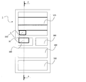
- FIG. 2 is a schematic diagram which shows the cross-section of the refrigerator 1 which concerns on Embodiment 1 of this invention.
- FIG. 2 shows an AA cross section of FIG.
- the refrigerator 1 is provided with a compressor 2 on the back side of the vegetable room 500, and is provided with a blower fan 4 for blowing cold air cooled by the cooler 3 and the cooler 3 to each room in the refrigerator on the back side of the freezing room 400. .
- the cold air cooled by the cooler 3 is blown to the freezing chamber 400, the switching chamber 200, the ice making chamber 300, and the refrigerating chamber 100 by the air passage 5 for introducing it into the respective storage chambers of the refrigerator 1, and each storing chamber Cool down.
- Vegetable room 500 is cooled by circulating return cold air of cold storage room 100 from return air course (not shown) for cold storage rooms. Then, it is returned to the cooler 3 from the return flow path (not shown) for the vegetable room.
- the temperature of each storage chamber is detected by a thermistor (not shown) installed in each storage chamber, and the degree of opening and compression of a damper (not shown) installed in the air passage 5 so as to reach a preset temperature. It is controlled by adjusting the operating condition of the machine 2 and the air flow rate of the air blowing fan 4.
- each storage chamber is schematically represented. Arrows displayed in FIG. 2 indicate the flow of cold air.
- Cold air cooled by the cooler 3 is fed into the ice making chamber 300 by the blower fan 4.
- the cold air is sent into the ice making chamber 300 via the cold air outlet 6.
- An ice tray 11 rotatably provided by a drive unit 12 is disposed in the ice making chamber 300.
- the cold air from the cold air outlet 6 is supplied to the upper space 302 above the ice tray 11 and exchanges heat with the water stored on the ice tray 11 to make ice.
- the upper side and the side of the ice tray 11 are surrounded by the ice machine cover 18 so that cold air is supplied to the upper space 302 of the ice tray 11 between the ice tray 11 and the ice machine cover 18 so as not to dissipate. ing.
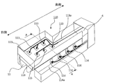
- FIG. 3 is a perspective view of the ice making device 10 according to the first embodiment of the present invention.
- FIG. 4 is a top view of the ice making device 10 of FIG.
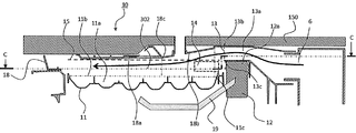
- FIG. 5 is a cross-sectional view of the ice making device 10 of FIG. FIG. 5 shows a cross section BB of FIG.
- the ice making device 10 is disposed in the ice making chamber 300.
- the ice making apparatus 10 is provided with an ice storage box 301 below the ice making tray 11, but is omitted in FIGS.
- An upper portion of the ice tray 11 is covered with an ice machine cover 18, and an upper space 302 in which cold air circulates is formed between the ice tray 11 and the ice machine cover 18.
- the ice tray 11 is rotatably supported by a drive unit 12 disposed on the back side of the ice making chamber 300.
- the driving unit 12 is a device for twisting the ice tray 11 and dropping the ice formed on the ice tray 11 into the ice storage box 301.
- an ice detecting lever 19 for detecting the amount of ice accumulated in the ice storage box 301 is provided below the ice making tray 11.
- the ice detecting lever 19 contacts the ice in the ice storage box 301, and the ice storage box 301 is flooded with ice by preventing the ice tray 11 from entering the ice separation operation when it does not go below a predetermined position. To prevent.
- an upper outlet 13 is provided above the ice tray 11 in the ice making chamber 300 and on the back side of the ice making chamber 300 relative to the ice tray 11.
- the upper air outlet 13 blows cold air passing through the upper duct 13 a from the cold air outlet 6 located on the back side of the ice making chamber 300, that is, the back side of the refrigerator 1 into the upper space 302 of the ice tray 11.
- the upper duct 13 a needs to pass through the drive unit 12 provided adjacent to the back side of the ice making tray 11 in the ice making chamber 300. Accordingly, the upper duct 13 a is provided adjacent to the upper side of the drive unit 12, and the upper outlet 13 is disposed adjacent to the upper side of the drive unit 12.
- the driving unit 12 is provided adjacent to the back side of the ice making tray 11 in the ice making chamber 300.
- the drive unit 12 has a mechanism for driving the ice tray 11 inside. Therefore, the upper portion of the drive unit 12 is provided to project above the water storage unit 11 a of the ice tray 11.
- the upper outlet 13 is opened above the upper portion of the drive unit 12.
- a ceiling surface 18 a is provided above the water reservoir 11 a of the ice tray 11.
- the ceiling surface 18 a is a lower surface of the ice making machine cover 18, and in particular, a portion located above the ice making tray 11 and facing the water storage portion 11 a of the ice making tray 11.
- the ceiling surface 18 a extends from the upper end 13 b of the upper outlet 13 toward the near side of the ice making chamber 300.
- the ceiling surface 18 a is horizontal from the upper end 13 b of the upper outlet 13 to the upper side of the rear end 11 c of the water reservoir 11 a of the ice tray 11, and is lowered toward the front side of the ice chamber 300 from there.
- the slope 18b is provided to be as follows.
- the ceiling surface 18 a is provided with a slope portion 18 b closer to the ice making plate 11 as it goes to the front side of the ice making room 300 in the region on the back side of the ice making room 300.
- the ceiling surface 18a is a part of icemaker cover 18, it is not limited to this form.
- the ceiling surface 18 may be configured by other structures inside the ice making chamber 300.
- the partition wall 150 which divides the icemaker 300 and the refrigerator compartment 100 may be comprised.
- the sloped portion 18 b of the ceiling surface 18 a is provided in a range from the central portion in the longitudinal direction of the ice tray 11 to the back side.
- the sloped end 18 c on the side closer to the ice tray 11 of the sloped portion 18 b is located on the upper side slightly behind the longitudinal center of the ice tray 11.
- the ceiling surface 18 a is substantially parallel to the water surface 11 b of the water storage portion 11 a of the ice tray 11 on the front side of the ice making chamber 300 from the slope end 18 c.
- the ceiling surface 18 a is formed so as not to interfere with the rotating trajectory of the ice tray 11 when the ice is dropped into the ice storage box 301. In FIG. 5, the ceiling surface 18 a is located above the upper limit line 15 of the rotation trajectory of the ice tray 11.
- FIG. 6 is a schematic view of the ice making device 10 according to Embodiment 1 of the present invention as viewed from above the ice making tray 11.
- 6 is a schematic view of a cross section taken along the line CC in FIG.
- a side outlet 14 is provided on the side of the ice tray 11.
- the side outlet 14 is provided on a wall of the ice making machine cover 18 on the side of the ice tray 11 and opens in a direction intersecting with the direction in which the upper outlet 13 is opened.
- the side air outlet 14 branches from the cold air outlet 6 located on the back side of the refrigerator 1 and blows the cold air having passed through the side duct 14 a into the upper space 302 of the ice tray 11.
- the side ducts 14a are also disposed apart from the drive portion 12.
- the portion shown by a dashed rectangle in FIG. 5 indicates the position of the side outlet 14.
- the side outlet 14 blows cold air onto the water storage portion 11 a of the portion near the drive portion 12 of the ice tray 11.
- the side air outlet 14 is located below the lower end 13 c of the upper air outlet 13. That is, the side outlets 14 are disposed toward the area of the corner formed by the upper portion of the drive portion and the water storage portion 11 a of the ice tray 11 in the upper space 302 of the ice tray 11.
- the upper space 302 of the ice tray 11 is shown in FIG. 5 surrounded by the upper end of the water storage section 11a, the drive section upper portion 12a, and a virtual surface horizontally extending the lower end 13c of the upper outlet 13.
- the side outlets 14 open towards the inner area of the U-shape. Further, the side air outlet 14 is located on the back side of the ice making chamber 300 than the sloped end 18c of the sloped portion 18b provided on the ceiling surface 18a. That is, the side outlets 14 are opened toward the upper space 302 of the ice tray 11 below the sloped portion 18 b of the ceiling surface 18 a of the ice making chamber 300.
- the cold air blown out from the upper outlet 13 flows along the sloped portion 18b of the ice making machine cover 18 on the extension in the blowing direction.
- the slope 18b has a slope of 10 degrees or less with respect to the blowing direction, so the pressure loss of the flow of cold air can be suppressed.
- Cold air blown out from the upper blowout port 13 and flowing along the ceiling surface 18 a is less likely to be separated from the ceiling surface 18 a due to the Coanda effect, and easily reaches the region on the near side of the ice making chamber 300.
- the side air outlet 14 is disposed below the lower end 13 c of the upper air outlet 13 and on the front side of the driving unit 12 in the ice making chamber 300. Therefore, the cold air blown out from the side air outlet 14 and the cold air blown out from the upper air outlet 13 do not collide near the upper air outlet 13 or near the side air outlet 14. Therefore, the cold air blown out from the upper outlet 13 is likely to reach onto the water reservoir 11 a on the ice tray 11 located on the front side of the ice making chamber 300.
- the cool air blown out from the side blow-off port 14 reaches the water reservoir 11a on the ice tray 11 near the drive unit 12 without being blocked by the cold air blown out from the upper blow-out port 13.
- FIG. 7 is a schematic view showing the structure of the ice making device 110 of the comparative example.
- FIG. 8 is an explanatory view of a structure in a cross section perpendicular to the longitudinal direction of the ice tray 11 including the upper outlet 113 and the side outlet 114 of the ice making apparatus 110 of FIG. 7.
- the ice making apparatus 110 of the comparative example is also provided in the refrigerator 1 in the same manner as the ice making apparatus 10 according to the first embodiment.
- an upper duct 113 a is provided above the ice tray 11, and a side duct 114 a is provided on the side of the ice tray 11.
- the cold air blown out from the cold air outlet 6 branches and flows into the upper duct 113a and the side duct 114a.
- the cold air which has flowed into the upper duct 113a is blown out from the plurality of upper outlets 113 provided on the lower surface of the upper duct 113a.
- the upper outlet 113 is disposed above the water reservoir 11 a of the ice tray 11 located on the front side of the ice making chamber 300.
- the cold air flowing from the cold air outlet 6 into the side duct 114a is blown out from the side outlets 114 arranged in plural on the side of the side duct 114a where the ice tray 11 is located.
- the side outlet 114 is disposed on the side of the water reservoir 11 a of the ice tray 11 located on the back side of the ice making chamber 300.
- the cold air blown out from the upper outlet 113 vertically collides with the surface of the water accumulated in the water reservoir 11 a on the ice tray 11. Therefore, the cold air that hits the water surface is bent horizontally and then rises upward. That is, in the upper space 302 of the ice tray 11 located between the ice tray 11 and the lower surface of the upper duct 13a, cold air containing water circulates in the vertical direction. Further, the cold air blown out from the side air outlet 114 joins the circulation of the cold air blown out from the upper air outlet 113 and circulates in the upper space 302 of the ice tray 11.
- frost adheres to a wall surface facing the upper space 302 and the like.
- the frost inhibits the rotation of the ice tray 11 by the drive unit 12 and causes a defect such as no ice making.
- the cold air from the upper air outlet 113 and the cold air from the side air outlet 114 collide, the cold air from the upper air outlet 113 is caused to flow laterally by the flow of the cold air from the side air outlet 114. Therefore, the cold air does not spread on the ice tray 11 on average, and the ice making of each part of the ice tray 11 varies.
- the cold air blown out from the upper blowout 13 passes above the side blowout 14 along the ceiling surface 18a, There is no collision with cold air blown out from the blowout port 14. Therefore, the cold air blown out from the upper outlet 13 reliably reaches the water reservoir 11 a on the ice tray 11 located on the front side of the ice making chamber 300. In addition, the cold air blown out from the side air outlet 14 does not flow into the cold air from the upper air outlet 13 and reaches the water storage portion 11 a on the driving portion 12 side of the ice tray 11.
- FIG. 9 is a cross-sectional view perpendicular to the longitudinal direction of the ice tray 11 of the ice making apparatus 10 of FIG.
- FIG. 9 shows a cross section including the upper duct 13 a, the side ducts 14 a, and the drive unit 12.
- the equivalent diameter d is calculated at a portion where the area of the cross section perpendicular to the flowing direction of the cold air in the upper duct 13a and the side duct 14a is the smallest.
- the equivalent diameter d 1 in the upper duct 13a is smaller than the equivalent diameter d 2 on the side duct 14a.
- the density of the cold air flowing through the high temperature upper duct 13a is reduced by the heat exchange with the ambient air, and the density of the cold air flowing through the side duct 14a and blown out from the side air outlet 14 is higher. Therefore, since the cold air blown out from the upper outlet 13 has a smaller density than the air blown out from the side outlets 14, buoyancy is generated. Due to the buoyancy, cold air blown out from the upper outlet 13 is unlikely to sink to the ice tray 11 side. Therefore, the cool air just blown out from the upper outlet 13 can easily reach the upper space 302 of the ice tray 11 on the near side of the ice making chamber 300 without contacting with the water stored in the ice tray 11 and exchanging heat.
- the cool air blown out from the upper blowout port 13 does not sink in the vicinity of the drive unit 12 due to the buoyancy generated from the density difference from the cold air blown out from the side blowout port 14.
- the cold air blown out from the upper blowout port 13 flows along the ceiling surface 18 a by the Coanda effect at a location away from the drive unit 12. Therefore, cold air which is not heat-exchanged with water is supplied to the water reservoir 11 a on the ice tray 11 located on the front side of the ice making chamber 300.
- the cold air blown out from the upper blowout port 13 is not sharply bent in the region on the drive unit 12 side on the ice tray 11, there is no pressure loss due to the bend flow. Furthermore, since the ceiling surface 18a is a smooth surface without providing a structure such as a protrusion to block the flow, the pressure loss of the cold air is small and the flow rate does not decrease. A sufficient amount of cold air can be supplied to the water storage section 11 a of the ice tray 11.
- the cold air blown out from the side outlet 14 is mainly supplied onto the water storage section 11 a of the ice tray 11 on the drive section 12 side, and exchanges heat with water, before the ice making room 300. It flows to the area of the side.
- cold air enters the cold air return port 20 on the side of the ice tray 11.
- cold air blown out from the upper blowout port 13 and supplied onto the water storage portion 11a of the ice tray 11 on the front side of the ice making room 300 also enters the cold air return port 20 after heat exchange with water.
- Equivalent diameter d 3 of the cool air return port 20 satisfies the following conditions represented using the equivalent diameter d 2 of the equivalent diameter d 1 and the side duct 14a of the upper duct 13a.
- the equivalent diameter d 3 of the cold air return port 20 is set to satisfy the relationship of 1 / d 3 ⁇ 1 / d 1 + 1 / d 2 . That is, the relationship of d 3 d d 1 d 2 / (d 1 + d 2 ) is satisfied. If the equivalent diameter d 3 of the cool air return port 20 of cooling air is the side to outflow above conditions are satisfied, the pressure loss on the side where cool air flows out decreases, inflow into cold return port 20 is increased.
- the cold air supplied to the upper space 302 of the ice tray 11 is likely to enter the cold air return port 20 without circulating and staying in the upper space 302. Therefore, it is possible to suppress the circulation of cold air containing water in the upper space 302, and to suppress the formation of frost in the ice making chamber 300. Further, by satisfying the condition of the equivalent diameter d 3 of the cool air return port 20, also increases the flow rate of the cool air flowing through the upper space 302 of the ice tray 11.
- the water stored on the side of the drive unit 12 on the ice tray 11 is cooled mainly by the cold air blown out from the side air outlet 14. Further, the water stored on the ice tray 11 on the front side of the ice making chamber 300 is mainly cooled by the cold air blown out from the upper outlet 13. In this way, cold air spreads on the ice tray 11 on average, and ice is uniformly made on the ice tray 11.
- the ice making apparatus according to the present invention can supply cold air to the entire ice making tray at a low cost and save space and perform uniform ice making without adding components such as a ceiling air path from the conventional ice making apparatus.
- the ice making apparatus 10 is the ice making apparatus 10 installed in the refrigerator 1 and is an ice tray with a longitudinal direction from the front side to the back side of the refrigerator 1
- the upper blowout port 13 and the upper blowout port 13 which are disposed above the ice chamber 300 where the 11 is disposed and above the back of the ice making chamber 300 than the ice making tray 11 and blows cold air into the space 302 above the ice making tray 11
- a side outlet 14 which is opened in a direction intersecting with the direction in which the air is blown and which blows cold air into the upper space 302 of the ice tray 11.
- the side outlets 14 are provided below the upper outlets 13.
- the cold air blown out from the upper outlet 13 and the cold air blown out from the side outlet 14 do not collide in the vicinity of the upper outlet 13 and the side outlets, and ice making It reaches a predetermined area on the plate 11. Accordingly, the cold air blown out from the upper blowout port 13 reaches the water storage portion 11 a of the ice making tray 11 located on the front side of the ice making chamber 300. In addition, the cold air blown out from the side air outlet 14 reaches the water storage portion 11 a of the ice making tray 11 located on the back side of the ice making chamber 300. In this manner, cold air can be supplied to the entire water storage portion 11a on the ice tray 11 without installing a duct at the top, and ice can be uniformly made on the ice tray 11 with a space saving.
- the ice tray 11 is disposed with the water reservoir 11a to be iced upward, and the ice making chamber 300 is positioned above the water reservoir 11a.
- a ceiling surface 18a facing the water reservoir 11a.
- the ceiling surface 18 a includes a slope portion 18 b which descends toward the ice making plate 11 as it goes from the back side to the front side of the ice making room 300.
- the sloped end 18 c located on the side closer to the ice tray 11 of the sloped portion 18 b is positioned on the front side of the ice making chamber 300 than the side outlet 14.
- the side air outlet 14 is located below the inclined surface 18 b of the ceiling surface 18 a, so that the cold air blown out from the upper air outlet 13 is blown out from the side air outlet 14. It passes above the cold air and easily reaches the water reservoir 11 a of the ice tray 11 located on the front side of the icemaker 300.
- the pressure loss can be suppressed, and the decrease in the flow rate can be suppressed.
- the ice making apparatus 10 includes the drive unit 12 for rotating the ice tray 11, the upper outlet 13 is disposed above the drive 12, and the side outlets 14 is disposed on the front side of the ice making chamber 300 relative to the drive unit 12.
- the drive unit 12 is disposed on the back side of the ice making chamber 300 with respect to the ice tray 11 so as to be adjacent to the ice tray 11 and has the drive unit upper portion 12 a protruding above the ice tray 11.
- the side outlet 14 is opened toward the corner area of the upper space 302 of the ice tray 11 formed by the upper end of the ice tray 11 and the upper portion 12 a of the drive unit.
- the side air outlet 14 supplies cold air to the corner between the upper end of the ice tray 11 and the upper portion 12a of the drive unit, so the cold air blown out from the upper air outlet 13 is bent sharply to There is no need to supply cold air to the corners. Therefore, the cold air blown out from the upper blowout port 13 does not have to be a bend flow, and the pressure loss can be suppressed.
- the cold air outlet 6 for blowing cold air the upper duct 13 a branched from the cold air outlet 6 and reaching the upper outlet 13, and the cold air outlet 6 And a side duct 14 a branched to the side outlet 14.
- Equivalent diameter d 1 of the cross section of the upper duct 13a is smaller than the equivalent diameter d 2 of the cross section of the side duct 14a.
- the ice making apparatus 10 includes the cold air return port 20 into which the cold air blown out from the upper air outlet 13 and the side air outlet 14 flows. 3 is larger than the equivalent diameter d 2 of the cross section of the side duct 14a.
Abstract
高さ方向寸法を抑えつつ、製氷皿上に均一に冷気を行き渡らせ製氷を均一に行うことができる冷蔵庫の製氷装置を提供する。冷蔵庫の製氷装置は、内部に冷蔵庫の手前側から奥側に製氷皿の長手方向を向けて配置した製氷室と、製氷皿に対し製氷室の奥側の上方に配置され、製氷皿の上方空間に冷気を吹き出す上部吹出口と、上部吹出口が開口している方向に対し交差する方向に開口し、製氷皿の上方空間に冷気を吹き出す側部吹出口と、を備える。側部吹出口は、上部吹出口よりも下方に設けられている。
Description
本発明は、冷蔵庫内に設けられた製氷装置に関し、特に冷気が循環する構造に関するものである。
従来、自動で製氷する製氷装置を備える冷蔵庫が知られている。特許文献1に開示されているように、冷蔵庫は、製氷室を備え、内部に駆動部により回転自在に設置された製氷皿が設置されている。製氷室には冷却器から冷気が供給され、製氷皿上の水を冷気により凍らせることにより製氷を行う。製氷皿上で製氷された氷は、駆動部で製氷皿を回転させることにより製氷皿の下方に配置された貯氷箱に落下し、貯蔵される。
製氷皿に冷気を導く冷気ダクトは、上方側冷気ダクトと側方側冷気ダクトとにより構成されている。上方側冷気ダクト及び側方側冷気ダクトは、駆動部を回避して設置されている。上方側冷気ダクトは、製氷皿の上方に配置されており、冷気導入孔を経て製氷皿の上方から冷気を供給する。側方冷気ダクトは、製氷皿の側方に設けられた冷気導入孔から製氷皿上に冷気を供給する。製氷皿上の水により昇温した冷気は、側方側の冷気導入孔と反対側の面から排出される。
特許文献1に開示されている冷蔵庫の製氷装置においては、製氷皿上の全ての場所において均一に製氷することを目的としている。そのため、製氷皿上に仕切られた貯水部の各区画に対応した冷気導入孔を上方側冷気ダクトに設けることにより、冷気を均等に分配し、製氷皿上の位置に寄らず安定した熱交換できるように構成されている。しかし、製氷皿の上方に冷気導入孔を設けた上方側冷気ダクトが配置されており、かつ製氷皿から離氷させるための回転駆動する空間を確保すると、製氷装置全体の高さ方向の寸法が大きくなるという課題があった。
また、上方側冷気ダクトから冷気導入孔を経て製氷皿上に供給された冷気は、垂直に吹き出すため、製氷皿上の水面に衝突した後に上方側冷気ダクトと水面との間を上下方向に循環する。循環する冷気は、水分を含んでおり、上方側冷気ダクトと水面との間の空間に面した壁面等に水分が付着し霜を発生させてしまうという課題があった。さらに、製氷室内の霜付きが過大に発生すると製氷皿の回転動作が阻害され、製氷皿からの離氷ができず、製氷できないという課題があった。
霜付きを防止するために側方側冷気ダクトの冷気導入孔からの冷気導入量を増加させると、上方側冷気ダクトから流入する冷気が側方側冷気ダクトからの冷気と衝突し側方に流される。そのため、製氷皿上に平均的に冷気が行き渡らず、均一に製氷できないという課題があった。
本発明は、上記のような課題を解決するためになされたもので、高さ方向寸法を抑えつつ、製氷皿上に均一に冷気を行き渡らせ製氷を均一に行うことができる冷蔵庫の製氷装置を提供することを目的とする。
本発明に係る製氷装置は、冷蔵庫内に設置された製氷装置であって、内部に、前記冷蔵庫の手前側から奥側に長手方向を向けた製氷皿が配置された製氷室と、前記製氷皿よりも前記製氷室の奥側の上方に配置され、前記製氷皿の上方空間に冷気を吹き出す上部吹出口と、前記上部吹出口が開口している方向に対し交差する方向に開口し、前記製氷皿の前記上方空間に前記冷気を吹き出す側部吹出口と、を備え、前記側部吹出口は、前記上部吹出口よりも下方に設けられている。
本発明に係る製氷装置によれば、製氷皿の上方にダクトを設置することなく製氷室の手前側の製氷皿上の水にも冷気を供給できるため、製氷装置の高さ方向の寸法を抑え省スペース化が図れる。
製氷皿の奥側に設けられた上部吹出口により、製氷室の手前側に位置する製氷皿上の水に上部吹出口からの冷気を供給することができる。また、側部吹出口は、上部吹出口よりも下方に設けられているため、上部吹出口から吹き出した冷気と側部吹出口から吹き出した冷気とが衝突せず、製氷室の手前側に位置する製氷皿上の水に上部吹出口からの冷気を供給しやすい。また、製氷皿の上方空間において水分を含んだ冷気が滞留するのを抑えることができ、着霜を抑制できる。
上部吹出口からの冷気は、上部吹出口を出た後に急激に製氷皿側に曲げられることがなく、製氷室奥側の製氷皿上に製氷室の天井面に沿って流れる。そのため、上部吹出口から出た冷気は、ベンド流による圧力損失が発生しないため流量が減少することが無く、製氷室手前側の製氷皿上の水に対する冷気の供給量が増加する。また、製氷室奥側の製氷皿上には、側部吹出口からの冷気を供給することができるため、製氷皿の全域にわたり冷気を供給することができ、製氷皿上の水を一様に製氷できる。
実施の形態1.
図1は、本発明の実施の形態1に係る冷蔵庫1の正面から見た模式図である。図1においては、冷蔵庫1の各貯蔵室を閉塞する扉を省略して表示している。冷蔵庫1は、最上部に冷蔵室100を備える。冷蔵室100の下方には、冷凍温度帯(-18℃)、冷蔵(3℃)、チルド(0℃)、及びソフト冷凍(-7℃)などの各温度帯に切り替えることのできる切替室200を備える。また、冷蔵室100の下方に切替室200と並列に製氷室300が配置されている。切替室200と製氷室300の下方には冷凍室400、冷凍室400の下方には野菜室500が配置されている。切替室200、製氷室300、冷凍室400、及び野菜室500は、引き出し式の扉を備えている。なお、冷蔵庫1の形態は図1に示されたものに限定されず、例えば、切替室200が無くともよい。
図1は、本発明の実施の形態1に係る冷蔵庫1の正面から見た模式図である。図1においては、冷蔵庫1の各貯蔵室を閉塞する扉を省略して表示している。冷蔵庫1は、最上部に冷蔵室100を備える。冷蔵室100の下方には、冷凍温度帯(-18℃)、冷蔵(3℃)、チルド(0℃)、及びソフト冷凍(-7℃)などの各温度帯に切り替えることのできる切替室200を備える。また、冷蔵室100の下方に切替室200と並列に製氷室300が配置されている。切替室200と製氷室300の下方には冷凍室400、冷凍室400の下方には野菜室500が配置されている。切替室200、製氷室300、冷凍室400、及び野菜室500は、引き出し式の扉を備えている。なお、冷蔵庫1の形態は図1に示されたものに限定されず、例えば、切替室200が無くともよい。
図2は、本発明の実施の形態1に係る冷蔵庫1の断面構造を示す模式図である。図2は、図1のA-A断面を示している。冷蔵庫1は、野菜室500の背面側に圧縮機2を備え、冷凍室400の背面側に冷却器3及び冷却器3により冷却された冷気を冷蔵庫内の各部屋へ送風する送風ファン4を備える。冷却器3により冷却された冷気は、冷蔵庫1の各貯蔵室に導入するための風路5により、冷凍室400、切替室200、製氷室300、及び冷蔵室100へと送風され、各貯蔵室を冷却する。野菜室500は、冷蔵室100の戻り冷気を冷蔵室用帰還風路(図示無し)より循環させることにより冷却される。そして、野菜室用帰還風路(図示無し)より冷却器3に戻される。各貯蔵室の温度は、各貯蔵室に設置されたサーミスタ(図示無し)により検知され、あらかじめ設定された温度になるように、風路5に設置されたダンパ(図示無し)の開度、圧縮機2の運転条件、及び送風ファン4の送風量を調整することで制御される。
図2において、各貯蔵室の構造は模式的に表されている。図2中に表示されている矢印は、冷気の流れを示している。製氷室300には、冷却器3により冷却された冷気が送風ファン4により送り込まれる。冷気は、冷気吹出口6を経て製氷室300内に送られる。製氷室300内は、駆動部12により回転自在に設けられた製氷皿11が配置されている。冷気吹出口6からの冷気は、製氷皿11の上方にある上方空間302に供給され、製氷皿11上に貯留された水と熱交換を行い製氷する。製氷皿11の上方及び側方は、製氷機カバー18により囲まれており、製氷皿11と製氷機カバー18との間にある製氷皿11の上方空間302に冷気が供給され散逸しないようになっている。
図3は、本発明の実施の形態1に係る製氷装置10の斜視図である。図4は、図3の製氷装置10の上面図である。図5は、図4の製氷装置10の断面図である。図5は、図4のB-B断面を表している。製氷装置10は、製氷室300内に配置されている。図2に示される様に、製氷装置10は、製氷皿11の下方に貯氷箱301を備えるが、図3~図5においては省略されている。
製氷皿11の上方は、製氷機カバー18により覆われており、製氷皿11と製氷機カバー18との間に冷気が循環する上方空間302が形成されている。製氷皿11は、製氷室300の奥側に配置されている駆動部12により回転自在に支持されている。駆動部12は、製氷皿11をひねり、製氷皿11上にできた氷を貯氷箱301へと落下させるための装置である。製氷皿11の下方には、貯氷箱301に溜まった氷の量を検知するための検氷レバー19が設けられている。検氷レバー19は、貯氷箱301内の氷と接触し、所定の位置よりも下がらない場合は、製氷皿11が離氷動作に入らないようにすることで、貯氷箱301が氷であふれることを防止している。
図5に示されるように、製氷室300内において製氷皿11より上方、かつ製氷皿11よりも製氷室300の奥側に上部吹出口13が設けられている。上部吹出口13は、製氷室300の奥側、つまり冷蔵庫1の背面側に位置する冷気吹出口6から上部ダクト13aを経た冷気を製氷皿11の上方空間302に吹き出す。上部ダクト13aは、製氷室300内において製氷皿11の奥側に隣合って設けられている駆動部12を避けて通す必要がある。従って、上部ダクト13aは、駆動部12の上方に隣接して設けられており、上部吹出口13は、駆動部12の上に隣接して配置されている。
駆動部12は、製氷室300内において製氷皿11の奥側に隣接して設けられている。駆動部12は、内部に製氷皿11を駆動させるための機構を備えている。そのため、駆動部12の上部は、製氷皿11の貯水部11aよりも上方に突出して設けられている。上部吹出口13は、駆動部12の上部のさらに上方に開口している。
製氷皿11の貯水部11aの上方には天井面18aが設けられている。天井面18aは、製氷機カバー18の下面であり、特に製氷皿11の上方に位置し、製氷皿11の貯水部11aに対向している部分である。天井面18aは、上部吹出口13の上端13bから製氷室300の手前側に向かって延びている。天井面18aは、上部吹出口13の上端13bから製氷皿11の貯水部11aの奥側端部11cの上方に至るまでは水平になっており、そこから製氷室300の手前側に向けて低くなるように斜面部18bが設けられている。つまり、天井面18aは、製氷室300の奥側の領域において製氷室300の手前側に行くに従い製氷皿11に近づくような斜面部18bが設けられている。なお、実施の形態1において、天井面18aは、製氷機カバー18の一部であるが、この形態に限定されるものではない。天井面18は、製氷室300の内部のその他の構造物により構成されていても良い。例えば、製氷室300と冷蔵室100とを区切る仕切壁150により構成されていても良い。
天井面18aの斜面部18bは、製氷皿11の長手方向の中央部より奥側までの範囲に設けられている。斜面部18bの製氷皿11に近い側の斜面端部18cは、製氷皿11の長手方向中央部よりやや奥側の上方に位置している。斜面端部18cから製氷室300の手前側においては、天井面18aは製氷皿11の貯水部11aの水面11bとほぼ平行になっている。天井面18aは、氷を貯氷箱301に落下させる際の製氷皿11の回転する軌跡に干渉しないように形成されている。図5において、天井面18aは、製氷皿11の回転軌跡の上限ライン15よりも上側に位置している。
図6は、本発明の実施の形態1に係る製氷装置10の製氷皿11の上方から見た模式図である。図6は、図5のC-C断面の模式図である。製氷皿11の側方には側部吹出口14が設けられている。側部吹出口14は、製氷機カバー18のうち、製氷皿11の側方にある壁に設けられており、上部吹出口13が開口している方向と交差する方向に向かって開口している。側部吹出口14は、冷蔵庫1の背面側に位置する冷気吹出口6から分岐し側部ダクト14aを経た冷気を製氷皿11の上方空間302に吹き出す。側部ダクト14aも上部ダクト13aと同様に駆動部12を避けて設置されている。
図5に破線で矩形に示された部分は、側部吹出口14の位置を示している。側部吹出口14は、製氷皿11の駆動部12寄りの部分の貯水部11aの上に冷気を吹き出す。また、側部吹出口14は、上部吹出口13の下端13cよりも下方に位置している。つまり、側部吹出口14は、製氷皿11の上方空間302のうち、駆動部上部と製氷皿11の貯水部11aとにより形成される隅の領域に向かって配置されている。言い換えると、製氷皿11の上方空間302は、貯水部11aの上端と、駆動部上部12aと、上部吹出口13の下端13cを水平に伸ばした仮想面と、により囲まれた、図5に示される断面においてコの字形状に区画された領域を有する。側部吹出口14は、そのコの字形状の内側の領域に向かって開口している。また、側部吹出口14は、天井面18aに設けられている斜面部18bの斜面端部18cよりも製氷室300の奥側に位置している。つまり、側部吹出口14は、製氷室300の天井面18aの斜面部18bの下方にある製氷皿11の上方空間302に向かって開口している。
図5に示されている様に、上部吹出口13から吹き出された冷気は、吹出し方向の延長上の製氷機カバー18の斜面部18bに沿って流れる。斜面部18bは、吹出方向に対して勾配を10度以下としているため、冷気の流れの圧力損失が抑えられる。上部吹出口13から吹き出され、天井面18aに沿って流れる冷気は、コアンダ効果により天井面18aから剥離しにくくなり、製氷室300の手前側の領域まで届きやすい。
また、側部吹出口14は、上部吹出口13の下端13cよりも下方で、製氷室300において駆動部12の手前側に配置されている。そのため、側部吹出口14から吹き出した冷気と上部吹出口13から吹き出した冷気とが、上部吹出口13の近傍又は側部吹出口14の近傍で衝突することが無い。従って、上部吹出口13から吹き出された冷気は、製氷室300の手前側に位置する製氷皿11上の貯水部11aの上に届きやすい。
側部吹出口14から吹き出された冷気は、上部吹出口13から吹き出された冷気に阻害されることなく駆動部12の近傍の製氷皿11上の貯水部11aに届く。
図7は、比較例の製氷装置110の構造を示す模式図である。図8は、図7の製氷装置110の上部吹出口113及び側部吹出口114を含んだ製氷皿11の長手方向に垂直な断面における構造の説明図である。比較例の製氷装置110も実施の形態1に係る製氷装置10と同様に冷蔵庫1内に設けられる。比較例の製氷装置110は、製氷皿11の上方に上部ダクト113aが設けられ、製氷皿11の側方に側部ダクト114aが設けられている。冷気吹出口6から吹き出された冷気は、分岐して上部ダクト113a及び側部ダクト114aに流れ込む。上部ダクト113aに流れ込んだ冷気は、上部ダクト113aの下面に複数設けられた上部吹出口113から吹き出す。上部吹出口113は、製氷室300の手前側に位置する製氷皿11の貯水部11aの上方に配置されている。
冷気吹出口6から側部ダクト114aに流れ込んだ冷気は、側部ダクト114aの製氷皿11が位置する側の側面に複数配置されている側部吹出口114から吹き出す。側部吹出口114は、製氷室300の奥側に位置する製氷皿11の貯水部11aの側方に配置されている。
図8に示される様に、上部吹出口113から吹き出された冷気は、製氷皿11上の貯水部11aに溜まった水の水面に垂直に衝突する。そのため、水面に当たった冷気は、水平方向に曲げられ、その後上方に上がる。つまり、製氷皿11と上部ダクト13aの下面との間に位置する製氷皿11の上方空間302で、水分を含んだ冷気が上下方向に循環する。また、側部吹出口114から吹き出された冷気は、上部吹出口113から吹き出された冷気の循環に合流し、製氷皿11の上方空間302で循環する。水分を含んだ冷気が製氷皿11の上方空間302で循環することにより、上方空間302に面する壁面などに霜が付着する。付着した霜が多くなると、霜が駆動部12による製氷皿11の回転を阻害し、製氷が行われない等の不具合の原因になる。
また、上部吹出口113からの冷気と側部吹出口114からの冷気とが衝突するため、側部吹出口114の冷気の流れにより上部吹出口113からの冷気が側方に流される。そのため、製氷皿11上に冷気が平均的に行き渡らず、製氷皿11の各部の製氷にばらつきが生じる。
一方、実施の形態1に係る製氷装置10は、図5に示される様に、上部吹出口13から吹き出された冷気は、側部吹出口14の上方を天井面18aに沿って通過し、側部吹出口14から吹き出された冷気と衝突することがない。従って、上部吹出口13から吹き出された冷気は、製氷室300の手前側に位置する製氷皿11上の貯水部11aに確実に届く。また、側部吹出口14から吹き出された冷気は、上部吹出口13からの冷気に流されることなく製氷皿11の駆動部12側の貯水部11aに届く。
図9は、図4の製氷装置10の製氷皿11の長手方向に垂直な断面図である。図9は、上部ダクト13a、側部ダクト14a、及び駆動部12を含む断面を示している。上部ダクト13aの断面における高さ方向寸法h1と幅方向寸法W1とから、上部ダクト13aの等価直径d1は、d1=(h1×W1)/(2h1+2W1)で求められる。同様にして、側部ダクト14aの等価直径d2も、側部ダクト14aの高さ方向寸法h2と幅方向寸法W2とから、d2=(h2×W2)/(2h2+2W2)で求められる。一般的にダクト内の流体の圧力損失は、等価直径d1に反比例する。すなわち、等価直径d1が小さくなるとダクト内を流れる流体の圧力が低下する。圧力損失によりダクト内の流体の圧力が低下すると、ダクト内の流体の流量は減少する。なお、等価直径dは、上部ダクト13a及び側部ダクト14a内の冷気が流れる方向に垂直な断面の面積が最も小さくなる部分で算出する。
実施の形態1に係る製氷装置10においては、上部ダクト13aにおける等価直径d1が側部ダクト14aにおける等価直径d2よりも小さい。これにより上部ダクト13aに流れる冷気の量Q1よりも側部ダクト14aに流れる冷気の量Q2のほうが多くなる。よって、冷気と周囲空気との熱交換が発生した場合、熱容量の小さい上部ダクト13aを流れる冷気のほうが側部ダクト14aを流れる冷気よりも温度上昇が大きくなる。空気密度ρは、空気温度をt、eを水蒸気圧、及びPを大気圧とすると、ρ=1.293×P/(1+t/273.15)×(1-0.378e/P)で求められる。つまり、空気温度が高いほど、空気密度は小さくなる。従って、周囲空気との熱交換により温度の高い上部ダクト13aを流れる冷気の密度が小さくなり、側部ダクト14aを流れ側部吹出口14から吹出される冷気の方が密度が高い。よって、上部吹出口13から吹き出される冷気は、側部吹出口14から吹き出される空気よりも密度が小さいため、浮力が生じる。その浮力により上部吹出口13から吹出す冷気は、製氷皿11側に沈みにくくなる。よって、上部吹出口13から吹き出されたばかりの冷気は、製氷皿11に貯水された水と接触、熱交換することなく、製氷室300の手前側の製氷皿11の上方空間302へ届きやすい。
上部吹出口13から吹出した冷気は、駆動部12近傍では側部吹出口14から吹出した冷気との密度差から生じる浮力により沈まない。また、上部吹出口13から吹出した冷気は、駆動部12から離れた箇所ではコアンダ効果により天井面18aに沿って流れる。そのため、水との熱交換がされていない冷気が、製氷室300の手前側に位置する製氷皿11上の貯水部11aまで供給される。
また、上部吹出口13から吹き出された冷気は、製氷皿11上の駆動部12側の領域で急激に曲げられることがないため、ベンド流による圧力損失がない。さらに、天井面18aは、突起などの流れを阻害する構造を設けずに滑らかな面であるため、冷気の圧力損失が少なく、流量が減少することがないため、製氷室300の手前側に位置する製氷皿11の貯水部11aまで十分な量の冷気を供給することができる。
図6に示される様に、側部吹出口14から吹き出される冷気は、主に駆動部12側の製氷皿11の貯水部11a上に供給され、水と熱交換し、製氷室300の手前側の領域に流れていく。製氷室300の手前側の製氷皿11の上方空間302において、冷気は製氷皿11の側方にある冷気戻り口20に入る。また、上部吹出口13から吹き出され、製氷室300の手前側の製氷皿11の貯水部11a上に供給された冷気も、水と熱交換した後冷気戻り口20に入る。
冷気戻り口20の等価直径d3は、上部ダクト13aの等価直径d1及び側部ダクト14aの等価直径d2を用いて表される次の条件を満たす。冷気戻り口20の等価直径d3は、1/d3≦1/d1+1/d2の関係を満たす様に設定される。つまり、d3≧d1d2/(d1+d2)の関係を満たす。冷気が流出する側である冷気戻り口20の等価直径d3が上記の条件を満たす場合、冷気が流出する側の圧力損失が小さくなり、冷気戻り口20への流入量が増加する。そのため、製氷皿11の上方空間302に供給された冷気は、上方空間302内で循環し滞留することなく冷気戻り口20に入りやすい。従って、水分を含んだ冷気が上方空間302内を循環するのを抑えられ、製氷室300内の着霜を抑えることができる。また、冷気戻り口20の等価直径d3が上記の条件を満たすことにより、製氷皿11の上方空間302を流通する冷気の流量も増加する。
以上のように、製氷皿11上の駆動部12側に貯まっている水は主に側部吹出口14から吹出される冷気により冷却される。また、製氷室300の手前側の製氷皿11上に貯まっている水は主に上部吹出口13から吹出される冷気により冷却される。このように、製氷皿11上に冷気が平均的に行き渡り、製氷皿11上に氷が一様に製氷される。本発明にかかる製氷装置は、従来の製氷装置から天井風路などの部品を追加することなく、低コストかつ省スペースで製氷皿全体へ冷気を供給し一様な製氷を行うことができる。
(実施の形態1の効果)
(1)本発明の実施の形態1に係る製氷装置10は、冷蔵庫1内に設置された製氷装置10であって、内部に、冷蔵庫1の手前側から奥側に長手方向を向けた製氷皿11が配置された製氷室300と、製氷皿11よりも製氷室300の奥側の上方に配置され、製氷皿11の上方空間302に冷気を吹き出す上部吹出口13と、上部吹出口13が開口している方向に対し交差する方向に開口し、製氷皿11の上方空間302に冷気を吹き出す側部吹出口14と、を備える。側部吹出口14は、上部吹出口13よりも下方に設けられている。
このように構成されることにより、上部吹出口13から吹き出される冷気と側部吹出口14から吹き出される冷気とが上部吹出口13及び側部吹出口の近傍で衝突することがなく、製氷皿11上の所定の領域に届く。従って、上部吹出口13から吹き出される冷気は、製氷室300の手前側に位置する製氷皿11の貯水部11aに届く。また、側部吹出口14から吹き出される冷気は、製氷室300の奥側に位置する製氷皿11の貯水部11aに届く。このように、上部にダクトを設置することなく製氷皿11上の貯水部11a全体に冷気を供給することができ、省スペースで製氷皿11上に一様に製氷を行うことができる。
(2)本発明の実施の形態1に係る製氷装置10によれば、製氷皿11は、製氷される貯水部11aを上方に向けて配置され、製氷室300は、貯水部11aの上方に位置し、貯水部11aに対向している天井面18aを備える。天井面18aは、製氷室300の奥側から手前側に行くにしたがい製氷皿11へ向かって下る斜面部18bを備える。斜面部18bの製氷皿11に近い側に位置する斜面端部18cは、側部吹出口14よりも製氷室300の手前側に位置する。
このように構成されることにより、側部吹出口14は、天井面18aの斜面部18bの下方に位置するため、上部吹出口13から吹き出された冷気は、側部吹出口14から吹き出された冷気の上を通過し、製氷室300の手前側に位置する製氷皿11の貯水部11aに届きやすくなる。また、上部吹出口13から吹き出された冷気は、緩やかな斜面部18bに沿ってながれるため、圧力損失を抑えることができ、流量の減少を抑えられる。
このように構成されることにより、側部吹出口14は、天井面18aの斜面部18bの下方に位置するため、上部吹出口13から吹き出された冷気は、側部吹出口14から吹き出された冷気の上を通過し、製氷室300の手前側に位置する製氷皿11の貯水部11aに届きやすくなる。また、上部吹出口13から吹き出された冷気は、緩やかな斜面部18bに沿ってながれるため、圧力損失を抑えることができ、流量の減少を抑えられる。
(3)本発明の実施の形態1に係る製氷装置10によれば、製氷皿11を回転させる駆動部12を備え、上部吹出口13は、駆動部12の上方に配置され、側部吹出口14は、駆動部12よりも製氷室300の手前側に配置される。
(4)また、駆動部12は、製氷皿11よりも製氷室300の奥側に製氷皿11に隣合って配置され、駆動部上部12aを製氷皿11よりも上方に突出させて配置される。側部吹出口14は、製氷皿11の上方空間302のうち、製氷皿11の上端と駆動部上部12aとにより形成された隅の領域に向かって開口している。
このように構成されることにより、側部吹出口14が、製氷皿11の上端と駆動部上部12aとの隅部に冷気を供給するため、上部吹出口13から吹き出す冷気を急激に曲げてその隅部に冷気を供給する必要がない。そのため、上部吹出口13から吹き出す冷気は、ベンド流にする必要がなく、圧力損失を抑えることができる。
(4)また、駆動部12は、製氷皿11よりも製氷室300の奥側に製氷皿11に隣合って配置され、駆動部上部12aを製氷皿11よりも上方に突出させて配置される。側部吹出口14は、製氷皿11の上方空間302のうち、製氷皿11の上端と駆動部上部12aとにより形成された隅の領域に向かって開口している。
このように構成されることにより、側部吹出口14が、製氷皿11の上端と駆動部上部12aとの隅部に冷気を供給するため、上部吹出口13から吹き出す冷気を急激に曲げてその隅部に冷気を供給する必要がない。そのため、上部吹出口13から吹き出す冷気は、ベンド流にする必要がなく、圧力損失を抑えることができる。
(5)本発明の実施の形態1に係る製氷装置10によれば、冷気を吹き出す冷気吹出口6と、冷気吹出口6から分岐し上部吹出口13に至る上部ダクト13aと、冷気吹出口6から分岐し側部吹出口14に至る側部ダクト14aと、を備える。上部ダクト13aの断面の等価直径d1は、側部ダクト14aの断面の等価直径d2よりも小さい。
このように構成されることにより、上部吹出口13から吹き出される冷気は、側部吹出口14から吹き出される冷気よりも密度が小さく、下に沈み込みにくい。そのため、冷気は、上部吹出口13を出た直後に下に沈みこまず、天井面18aに沿って流れやすい。
このように構成されることにより、上部吹出口13から吹き出される冷気は、側部吹出口14から吹き出される冷気よりも密度が小さく、下に沈み込みにくい。そのため、冷気は、上部吹出口13を出た直後に下に沈みこまず、天井面18aに沿って流れやすい。
(6)本発明の実施の形態1に係る製氷装置10によれば、上部吹出口13及び側部吹出口14から吹き出した冷気が流れ込む冷気戻り口20を備え、冷気戻り口20の等価直径d3は、側部ダクト14aの断面の等価直径d2よりも大きい。
このように構成されることにより、製氷皿11の上方空間302に供給された冷気は、上方空間302内で循環し滞留することなく冷気戻り口20に入りやすい。従って、水分を含んだ冷気が上方空間302内を循環するのを抑えられ、製氷室300内の着霜を抑えることができる。
このように構成されることにより、製氷皿11の上方空間302に供給された冷気は、上方空間302内で循環し滞留することなく冷気戻り口20に入りやすい。従って、水分を含んだ冷気が上方空間302内を循環するのを抑えられ、製氷室300内の着霜を抑えることができる。
1 冷蔵庫、2 圧縮機、3 冷却器、4 送風ファン、5 風路、6 冷気吹出口、10 製氷装置、11 製氷皿、11a 貯水部、11b 水面、11c 奥側端部、12 駆動部、12a 駆動部上部、13 上部吹出口、13a 上部ダクト、13b 上端、13c 下端、14 側部吹出口、14a 側部ダクト、15 上限ライン、18 製氷機カバー、18a 天井面、18b 斜面部、18c 斜面端部、19 検氷レバー、20 冷気戻り口、100 冷蔵室、110 製氷装置、113 上部吹出口、113a 上部ダクト、114 側部吹出口、114a 側部ダクト、200 切替室、300 製氷室、301 貯氷箱、302 上方空間、400 冷凍室、500 野菜室、Q1 量、Q2 量、W1 幅方向寸法、W2 幅方向寸法、d1 等価直径、d2 等価直径、h1 高さ方向寸法、h2 高さ方向寸法、ρ 空気密度。
Claims (6)
- 冷蔵庫内に設置された製氷装置であって、
内部に、前記冷蔵庫の手前側から奥側に長手方向を向けた製氷皿が配置された製氷室と、
前記製氷皿よりも前記製氷室の奥側の上方に配置され、前記製氷皿の上方空間に冷気を吹き出す上部吹出口と、
前記上部吹出口が開口している方向に対し交差する方向に開口し、前記製氷皿の前記上方空間に前記冷気を吹き出す側部吹出口と、を備え、
前記側部吹出口は、
前記上部吹出口よりも下方に設けられている、製氷装置。 - 前記製氷皿は、
製氷される貯水部を上方に向けて配置され、
前記製氷室は、
前記貯水部の上方に位置し、前記貯水部に対向している天井面を備え、
前記天井面は、
前記製氷室の奥側から手前側に行くにしたがい前記製氷皿へ向かって下る斜面部を備え、
前記斜面部の前記製氷皿に近い側に位置する斜面端部は、
前記側部吹出口よりも前記製氷室の手前側に位置する、請求項1に記載の製氷装置。 - 前記製氷皿を回転させる駆動部を備え、
前記上部吹出口は、
前記駆動部の上方に配置され、
前記側部吹出口は、
前記駆動部よりも前記製氷室の手前側に配置される、請求項1又は2に記載の製氷装置。 - 前記駆動部は、
前記製氷皿よりも前記製氷室の奥側に前記製氷皿に隣合って配置され、駆動部上部を前記製氷皿よりも上方に突出させて配置され、
前記側部吹出口は、
前記製氷皿の前記上方空間のうち、前記製氷皿の上端と前記駆動部上部とにより形成された隅の領域に向かって開口している、請求項3に記載の製氷装置。 - 前記冷気を吹き出す冷気吹出口と、
前記冷気吹出口から分岐し前記上部吹出口に至る上部ダクトと、
前記冷気吹出口から分岐し前記側部吹出口に至る側部ダクトと、を備え、
前記上部ダクトの断面の等価直径d1は、
前記側部ダクトの断面の等価直径d2よりも小さい、請求項1~4の何れか1項に記載の製氷装置。 - 前記上部吹出口及び前記側部吹出口から吹き出した前記冷気が流れ込む冷気戻り口を備え、
前記冷気戻り口の等価直径d3は、
d3≧d1d2/(d1+d2)の関係を満たす、請求項5に記載の製氷装置。
Priority Applications (5)
| Application Number | Priority Date | Filing Date | Title |
|---|---|---|---|
| PCT/JP2017/043647 WO2019111321A1 (ja) | 2017-12-05 | 2017-12-05 | 製氷装置 |
| JP2019557899A JP6937843B2 (ja) | 2017-12-05 | 2017-12-05 | 製氷装置 |
| TW107136955A TWI682136B (zh) | 2017-12-05 | 2018-10-19 | 製冰裝置 |
| CN201811382760.8A CN109974361B (zh) | 2017-12-05 | 2018-11-20 | 制冰装置 |
| CN201821919159.3U CN209310321U (zh) | 2017-12-05 | 2018-11-20 | 制冰装置 |
Applications Claiming Priority (1)
| Application Number | Priority Date | Filing Date | Title |
|---|---|---|---|
| PCT/JP2017/043647 WO2019111321A1 (ja) | 2017-12-05 | 2017-12-05 | 製氷装置 |
Publications (1)
| Publication Number | Publication Date |
|---|---|
| WO2019111321A1 true WO2019111321A1 (ja) | 2019-06-13 |
Family
ID=66750840
Family Applications (1)
| Application Number | Title | Priority Date | Filing Date |
|---|---|---|---|
| PCT/JP2017/043647 WO2019111321A1 (ja) | 2017-12-05 | 2017-12-05 | 製氷装置 |
Country Status (4)
| Country | Link |
|---|---|
| JP (1) | JP6937843B2 (ja) |
| CN (2) | CN209310321U (ja) |
| TW (1) | TWI682136B (ja) |
| WO (1) | WO2019111321A1 (ja) |
Families Citing this family (1)
| Publication number | Priority date | Publication date | Assignee | Title |
|---|---|---|---|---|
| WO2019111321A1 (ja) * | 2017-12-05 | 2019-06-13 | 三菱電機株式会社 | 製氷装置 |
Citations (3)
| Publication number | Priority date | Publication date | Assignee | Title |
|---|---|---|---|---|
| JPS637770U (ja) * | 1986-07-02 | 1988-01-19 | ||
| JP2010043823A (ja) * | 2008-07-18 | 2010-02-25 | Panasonic Corp | 冷蔵庫 |
| JP2017517713A (ja) * | 2014-06-11 | 2017-06-29 | 合肥華凌股▲フン▼有限公司 | 空冷式冷蔵庫 |
Family Cites Families (12)
| Publication number | Priority date | Publication date | Assignee | Title |
|---|---|---|---|---|
| JPH04313661A (ja) * | 1991-04-10 | 1992-11-05 | Toshiba Corp | 製氷装置 |
| JPH11223450A (ja) * | 1998-02-04 | 1999-08-17 | Toshiba Corp | 冷蔵庫 |
| JP2003130510A (ja) * | 2001-10-24 | 2003-05-08 | Sanyo Electric Co Ltd | 製氷装置及びこの装置を備えた冷凍冷蔵庫 |
| JP2006250489A (ja) * | 2005-03-14 | 2006-09-21 | Matsushita Electric Ind Co Ltd | 冷蔵庫の製氷装置 |
| JP5142835B2 (ja) * | 2008-06-06 | 2013-02-13 | 日立アプライアンス株式会社 | 製氷装置及び該製氷装置を備える冷蔵庫 |
| JP5586534B2 (ja) * | 2011-07-01 | 2014-09-10 | 三菱電機株式会社 | 冷凍冷蔵庫 |
| JP6061808B2 (ja) * | 2013-08-07 | 2017-01-18 | 三菱電機株式会社 | 冷蔵庫 |
| KR101715806B1 (ko) * | 2015-06-16 | 2017-03-13 | 동부대우전자 주식회사 | 냉장고의 제빙시스템 및 제빙방법 |
| CN105299994B (zh) * | 2015-10-29 | 2017-12-29 | 合肥海尔电冰箱有限公司 | 制冰装置和冰箱 |
| US10101074B2 (en) * | 2016-04-21 | 2018-10-16 | Electrolux Home Products, Inc. | Ice maker air flow ribs |
| KR101798553B1 (ko) * | 2016-04-22 | 2017-12-12 | 동부대우전자 주식회사 | 냉장고용 제빙장치 및 이를 포함하는 냉장고 |
| WO2019111321A1 (ja) * | 2017-12-05 | 2019-06-13 | 三菱電機株式会社 | 製氷装置 |
-
2017
- 2017-12-05 WO PCT/JP2017/043647 patent/WO2019111321A1/ja active Application Filing
- 2017-12-05 JP JP2019557899A patent/JP6937843B2/ja active Active
-
2018
- 2018-10-19 TW TW107136955A patent/TWI682136B/zh active
- 2018-11-20 CN CN201821919159.3U patent/CN209310321U/zh active Active
- 2018-11-20 CN CN201811382760.8A patent/CN109974361B/zh active Active
Patent Citations (3)
| Publication number | Priority date | Publication date | Assignee | Title |
|---|---|---|---|---|
| JPS637770U (ja) * | 1986-07-02 | 1988-01-19 | ||
| JP2010043823A (ja) * | 2008-07-18 | 2010-02-25 | Panasonic Corp | 冷蔵庫 |
| JP2017517713A (ja) * | 2014-06-11 | 2017-06-29 | 合肥華凌股▲フン▼有限公司 | 空冷式冷蔵庫 |
Also Published As
| Publication number | Publication date |
|---|---|
| JP6937843B2 (ja) | 2021-09-22 |
| CN109974361B (zh) | 2021-09-28 |
| CN109974361A (zh) | 2019-07-05 |
| TW201925705A (zh) | 2019-07-01 |
| CN209310321U (zh) | 2019-08-27 |
| TWI682136B (zh) | 2020-01-11 |
| JPWO2019111321A1 (ja) | 2020-07-16 |
Similar Documents
| Publication | Publication Date | Title |
|---|---|---|
| JP5903552B2 (ja) | 冷蔵庫 | |
| JP4663463B2 (ja) | 冷却機器の冷気流通構造 | |
| WO2018064866A1 (zh) | 冰箱 | |
| KR20180132317A (ko) | 냉장고 | |
| JP7126675B2 (ja) | 冷蔵庫 | |
| WO2019129242A1 (zh) | 冰箱 | |
| WO2019111321A1 (ja) | 製氷装置 | |
| KR101645731B1 (ko) | 냉장고 | |
| JP6584674B2 (ja) | 冷蔵庫 | |
| JP2018179466A (ja) | 冷蔵庫 | |
| JP2014167361A (ja) | 冷蔵庫 | |
| JP2015197283A (ja) | 冷蔵庫 | |
| JP2003240407A (ja) | 冷蔵庫 | |
| JP2018179469A (ja) | 冷蔵庫 | |
| JP2002340465A (ja) | 冷蔵庫 | |
| JP6726836B2 (ja) | 冷蔵庫 | |
| JP4203662B2 (ja) | 冷蔵庫 | |
| JP2018077036A (ja) | ダンパ装置およびそれを用いた冷蔵庫 | |
| JP6625141B2 (ja) | 冷蔵庫 | |
| JP2022112627A (ja) | 冷蔵庫 | |
| JP5877297B2 (ja) | 冷蔵庫 | |
| JP2017058075A (ja) | 冷蔵庫 | |
| TW202303058A (zh) | 冰箱 | |
| JP2022070727A (ja) | 冷蔵庫 | |
| TW201113487A (en) | Refrigerator |
Legal Events
| Date | Code | Title | Description |
|---|---|---|---|
| 121 | Ep: the epo has been informed by wipo that ep was designated in this application |
Ref document number: 17934355 Country of ref document: EP Kind code of ref document: A1 |
|
| ENP | Entry into the national phase |
Ref document number: 2019557899 Country of ref document: JP Kind code of ref document: A |
|
| NENP | Non-entry into the national phase |
Ref country code: DE |
|
| 122 | Ep: pct application non-entry in european phase |
Ref document number: 17934355 Country of ref document: EP Kind code of ref document: A1 |