WO2019093402A1 - ソレノイド装置 - Google Patents
ソレノイド装置 Download PDFInfo
- Publication number
- WO2019093402A1 WO2019093402A1 PCT/JP2018/041422 JP2018041422W WO2019093402A1 WO 2019093402 A1 WO2019093402 A1 WO 2019093402A1 JP 2018041422 W JP2018041422 W JP 2018041422W WO 2019093402 A1 WO2019093402 A1 WO 2019093402A1
- Authority
- WO
- WIPO (PCT)
- Prior art keywords
- spring
- movable core
- magnetic
- core
- magnetic spring
- Prior art date
- Legal status (The legal status is an assumption and is not a legal conclusion. Google has not performed a legal analysis and makes no representation as to the accuracy of the status listed.)
- Ceased
Links
Images







Classifications
-
- H—ELECTRICITY
- H01—ELECTRIC ELEMENTS
- H01F—MAGNETS; INDUCTANCES; TRANSFORMERS; SELECTION OF MATERIALS FOR THEIR MAGNETIC PROPERTIES
- H01F7/00—Magnets
- H01F7/06—Electromagnets; Actuators including electromagnets
- H01F7/08—Electromagnets; Actuators including electromagnets with armatures
- H01F7/16—Rectilinearly-movable armatures
-
- H—ELECTRICITY
- H01—ELECTRIC ELEMENTS
- H01F—MAGNETS; INDUCTANCES; TRANSFORMERS; SELECTION OF MATERIALS FOR THEIR MAGNETIC PROPERTIES
- H01F7/00—Magnets
- H01F7/06—Electromagnets; Actuators including electromagnets
- H01F7/08—Electromagnets; Actuators including electromagnets with armatures
- H01F7/16—Rectilinearly-movable armatures
- H01F7/1638—Armatures not entering the winding
-
- H—ELECTRICITY
- H01—ELECTRIC ELEMENTS
- H01F—MAGNETS; INDUCTANCES; TRANSFORMERS; SELECTION OF MATERIALS FOR THEIR MAGNETIC PROPERTIES
- H01F27/00—Details of transformers or inductances, in general
- H01F27/24—Magnetic cores
-
- H—ELECTRICITY
- H01—ELECTRIC ELEMENTS
- H01F—MAGNETS; INDUCTANCES; TRANSFORMERS; SELECTION OF MATERIALS FOR THEIR MAGNETIC PROPERTIES
- H01F27/00—Details of transformers or inductances, in general
- H01F27/28—Coils; Windings; Conductive connections
-
- H—ELECTRICITY
- H01—ELECTRIC ELEMENTS
- H01F—MAGNETS; INDUCTANCES; TRANSFORMERS; SELECTION OF MATERIALS FOR THEIR MAGNETIC PROPERTIES
- H01F7/00—Magnets
- H01F7/06—Electromagnets; Actuators including electromagnets
- H01F7/08—Electromagnets; Actuators including electromagnets with armatures
- H01F7/081—Magnetic constructions
-
- H—ELECTRICITY
- H01—ELECTRIC ELEMENTS
- H01F—MAGNETS; INDUCTANCES; TRANSFORMERS; SELECTION OF MATERIALS FOR THEIR MAGNETIC PROPERTIES
- H01F7/00—Magnets
- H01F7/06—Electromagnets; Actuators including electromagnets
- H01F7/08—Electromagnets; Actuators including electromagnets with armatures
- H01F7/121—Guiding or setting position of armatures, e.g. retaining armatures in their end position
-
- H—ELECTRICITY
- H01—ELECTRIC ELEMENTS
- H01F—MAGNETS; INDUCTANCES; TRANSFORMERS; SELECTION OF MATERIALS FOR THEIR MAGNETIC PROPERTIES
- H01F7/00—Magnets
- H01F7/06—Electromagnets; Actuators including electromagnets
- H01F7/08—Electromagnets; Actuators including electromagnets with armatures
- H01F7/081—Magnetic constructions
- H01F2007/086—Structural details of the armature
Definitions
- the present disclosure relates to a solenoid device including an electromagnetic coil and a movable core that moves forward and backward depending on whether or not current is supplied to the electromagnetic coil.
- a solenoid device is conventionally known that includes an electromagnetic coil and a movable core that moves forward and backward depending on whether or not current is supplied to the electromagnetic coil (see Patent Document 1 below).
- a fixed core made of a magnetic material is provided in the electromagnetic coil.
- a spring member is provided between the fixed core and the movable core. The spring member pressurizes the movable core in a direction away from the fixed core in the axial direction of the electromagnetic coil.
- the solenoid device causes the movable core to move back and forth depending on whether or not the electromagnetic coil is energized.
- the spring member is made of a nonmagnetic material. Therefore, in the solenoid device, the magnetic resistance of the portion where the spring member is disposed is high, and the movable core can not be attracted by a strong force unless a large current flows through the electromagnetic coil.
- a spring member having a shape in which the central portion is positioned on one side in the axial direction with respect to the peripheral portion in a state in which no force is applied in the axial direction.
- a magnetic spring see FIG. 4). If such a magnetic spring is used, the magnetic resistance at the portion where the magnetic spring is disposed (that is, between the fixed core and the movable core) can be reduced. Therefore, it is considered that the magnetic flux of the electromagnetic coil flows easily, and the movable core can be attracted by a strong force even if the amount of current flowing through the electromagnetic coil is small.
- the solenoid device has a large difference in suction force. That is, in the solenoid device, when the movable core is attracted, the magnetic spring is deformed to the width of the plate-like spring (that is, the minimum spring length of the magnetic spring). In the magnetic spring, when a force is applied in the axial direction from the natural length state, the spring length is gradually shortened and the spring force is increased (see FIG. 6). When the magnetic spring is sufficiently longer than the minimum spring length, the amount of displacement from the natural length and the spring force are in a substantially proportional relationship, but the spring force suddenly increases near the minimum spring length. Moreover, in the vicinity of the minimum spring length, the product variation of the spring force is large.
- the product variation of the spring force is large, so the spring force of the magnetic spring is subtracted from the attraction force of the movable core (that is, the electromagnetic force generated by energization of the electromagnetic coil). Power) is likely to vary. Therefore, there is a possibility that the suction force is insufficient and the movable core can not be suctioned, or the speed at which the movable core is suctioned may vary widely.
- the present disclosure is intended to provide a solenoid device that can reduce product variation in the suction force of the movable core.
- One aspect of the present disclosure is an electromagnetic coil in which magnetic flux is generated by energization.
- a stationary core disposed in the electromagnetic coil;
- a movable core that moves back and forth in the axial direction of the electromagnetic coil depending on whether or not the electromagnetic coil is energized;
- a magnetic spring which is disposed between the fixed core and the movable core and made of a magnetic material, and biases the movable core in the direction away from the fixed core in the axial direction;
- the magnetic spring, the movable core, and the fixed core, and a yoke forming a magnetic circuit in which the magnetic flux flows,
- the movable core is attracted to the approach position relatively close to the fixed core against the spring force of the magnetic spring by the generated electromagnetic force when the electromagnetic coil is energized, and the movable core is moved to the electromagnetic coil.
- the magnetic spring is formed by spirally winding a plate-like spring member made of the magnetic body so that the thickness direction of the plate-like spring member matches the radial direction of the electromagnetic coil, and the central portion is a peripheral edge Located on one side in the axial direction above the
- the solenoid device is configured such that the magnetic spring does not deform to a minimum spring length which is a width of the plate-like spring member in the axial direction when the movable core is attracted to the approaching position.
- the magnetic spring when the movable core is attracted to the approaching position, the magnetic spring is configured not to deform to the minimum spring length. Therefore, it is not necessary to use a region where the product variation of the spring force of the magnetic spring is large (near the minimum spring length), and the attractive force of the movable core (i.e., the electromagnetic force generated by energizing the electromagnetic coil It is possible to suppress the variation of the force). Therefore, it is possible to suppress that the suction force is insufficient and the movable core can not be suctioned or the suction speed of the movable core is largely dispersed.
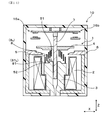
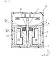
- FIG. 1 is a cross-sectional view of the solenoid device in a state in which the electromagnetic coil is not energized in the first embodiment
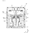
- FIG. 2 is a cross-sectional view of the solenoid device immediately after the electromagnetic coil is energized in the first embodiment
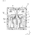
- FIG. 3 is a cross-sectional view of the solenoid device in the state in which the electromagnetic coil is energized in the first embodiment
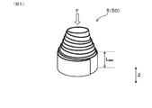
- FIG. 4 is a perspective view of a magnetic spring in which no force is applied in the first embodiment
- FIG. 5 is a perspective view of an axially applied magnetic spring according to the first embodiment
- FIG. 1 is a cross-sectional view of the solenoid device in a state in which the electromagnetic coil is not energized in the first embodiment
- FIG. 2 is a cross-sectional view of the solenoid device immediately after the electromagnetic coil is energized in the first embodiment
- FIG. 3 is a cross-sectional view of the solenoid device in the state in which the electromagnetic coil is energized in the first embodiment
- FIG. 6 is a graph showing the relationship between the spring length of the magnetic spring and the spring force in the first embodiment
- 7 is a perspective view of the solenoid device in the first embodiment
- FIG. 8 is an operation explanatory diagram of a relay system using a solenoid device according to the first embodiment
- FIG. 9 is a view following FIG. 8
- FIG. 10 is a view following FIG. 9
- 11 is a view following FIG. 10
- FIG. 12 is a cross-sectional view of the solenoid device in a state in which the electromagnetic coil is not energized in the second embodiment
- FIG. 13 is a cross-sectional view of the solenoid device in a state in which the electromagnetic coil is energized in the second embodiment
- 14 is a cross-sectional view of the solenoid device in a state in which the electromagnetic coil is not energized in the third embodiment
- FIG. 15 is a cross-sectional view of the solenoid device in a state in which the electromagnetic coil is energized in the third embodiment
- 16 is a cross-sectional view of the solenoid device in a state in which the electromagnetic coil is not energized in the fourth embodiment
- FIG. 17 is a cross-sectional view of the solenoid device in a state in which the electromagnetic coil is energized in the fourth embodiment
- 18 is a cross-sectional view of the solenoid device in a state in which the electromagnetic coil is not energized in the fifth embodiment
- FIG. 19 is a cross-sectional view of the solenoid device in a state in which the electromagnetic coil is energized in the fifth embodiment
- FIG. 20 is a cross-sectional view of the solenoid device in a state in which the electromagnetic coil is not energized in the sixth embodiment
- FIG. 21 is a cross-sectional view of the solenoid device in a state in which the electromagnetic coil is energized in the sixth embodiment
- FIG. 22 is a cross-sectional view of the solenoid device in a state in which the electromagnetic coil is not energized in the seventh embodiment
- FIG. 23 is a cross-sectional view of the solenoid device in a state in which the electromagnetic coil is energized in the seventh embodiment
- 24 is a cross-sectional view of the solenoid device in a state in which the electromagnetic coil is not energized in the eighth embodiment
- FIG. 25 is a cross-sectional view of the solenoid device in a state in which the electromagnetic coil is energized in the eighth embodiment
- FIG. 26 is a cross-sectional view of the solenoid device in a state in which the electromagnetic coil is not energized in the ninth embodiment
- FIG. 27 is a cross-sectional view of the solenoid device in a state in which the electromagnetic coil is energized in the ninth embodiment.
- the solenoid device 1 of this embodiment includes an electromagnetic coil 2 that generates a magnetic flux ⁇ when energized, a fixed core 3, a movable core 4, a magnetic spring 5, and a yoke 6.
- the fixed core 3 is disposed in the electromagnetic coil 2.
- the movable core 4 moves back and forth in the axial direction (Z direction) of the electromagnetic coil 2 depending on whether or not the electromagnetic coil 2 is energized.
- the magnetic spring 5 is disposed between the fixed core 3 and the movable core 4.
- the magnetic spring 5 is made of a magnetic material, and biases the movable core 4 in a direction away from the fixed core 3 in the Z direction.
- the yoke 6, together with the magnetic spring 5, the movable core 4 and the fixed core 3, constitutes a magnetic circuit C in which the magnetic flux ⁇ flows.
- the movable core 4 is attracted to an approach position relatively close to the fixed core 3 against the spring force of the magnetic spring 5 by the generated electromagnetic force when the electromagnetic coil 2 is energized. Ru. Further, as shown in FIG. 1, when the energization of the electromagnetic coil 2 is stopped, the movable core 4 moves to a separated position separated from the fixed core 3 by the spring force of the magnetic spring 5.
- the magnetic spring 5 is formed into a spiral shape so that the thickness direction of the plate-like spring member 50 matches the radial direction of the electromagnetic coil 2. It is wound, and the center part 51 is configured to be positioned on one side in the Z direction with respect to the peripheral part 52.
- the magnetic spring 5 is configured not to deform to the minimum spring length L MIN which is the width of the plate-like spring member 50.
- the solenoid device 1 of the present embodiment is used for the electromagnetic relay 10.
- the electromagnetic relay 10 includes a switch 16 (16 a, 16 b) . By moving the movable core 4 forward and backward, the switch 16 is turned on and off.
- the solenoid device 1 includes a shaft 7 inserted in a fixed core 3.
- the shaft 7 is made of a nonmagnetic material.
- the tip 71 of the shaft 7 is formed of an insulating material.
- the yoke 6 has a bottom wall 63, a side wall 62, and an upper wall 61.
- a through hole 610 is formed in the upper wall portion 61.
- the movable core 4 is fitted in the through hole 610.
- a stopper 611 is formed to stop the movable core 4 at the above approach position.
- the electromagnetic relay 10 includes a fixed conductive portion 13, a movable conductive portion 12, a fixed side contact 15 formed on the fixed conductive portion 13, and a movable side contact 14 formed on the movable conductive portion 12. Equipped with The conductive portions 12 and 13 and the contacts 14 and 15 constitute a switch 16 (16 a , 16 b ).
- a switch-side spring member 17 is provided between the movable conductive portion 12 and the wall portion 111 of the case 11. The switch-side spring member 17 presses the movable conductive portion 12 toward the fixed core 3 in the Z direction.
- a magnetic flux ⁇ is generated.
- the magnetic flux ⁇ flows from the fixed core 3 to the magnetic spring 5 and further flows through the movable core 4, the gap G, and the yoke 6.
- a part of the magnetic flux ⁇ also flows into the space S between the fixed core 3 and the magnetic spring 5.
- the magnetic flux ⁇ also flows in the space between the movable core 4 and the magnetic spring 5.
- the relationship between the length of the magnetic spring 5 and the spring force will be described.
- the length of the spring is gradually shortened and the spring force is increased.
- the magnetic spring 5 is sufficiently longer than the minimum spring length LMIN , the displacement from the natural length and the spring force are in a substantially proportional relationship.
- the spring force suddenly increases near the minimum spring length L MIN .
- the spring force at the minimum spring around the length L MIN is larger manufacturing variations. Therefore, assuming that the magnetic spring 5 is deformed to the minimum spring length L MIN when the movable core 4 (see FIG.
- the manufacturing variation of the spring force is large, so the movable core 4 is sufficiently attracted.
- the suction speed of the movable core 4 may be decreased.
- the magnetic spring 5 since the magnetic spring 5 is not deformed to the minimum spring length L MIN (see FIG. 3), it is not easily affected by variations in spring force. Therefore, the movable core 4 can be reliably attracted to the approach position. Moreover, the variation in the suction speed of the movable core 4 can be suppressed.
- only the region of the magnetic spring 5 in which the displacement amount and the spring force are substantially proportional can be used, so the design of the magnetic spring 5 is facilitated.
- the relay system 19 is configured using the electromagnetic relay 10.
- the relay system 19 includes three electromagnetic relays 10, a DC power supply 72, a smoothing capacitor 75, an electrical device 73, a precharge resistor 76, and a control unit 74.
- the controller 74 controls the on / off operation of each of the electromagnetic relays 10.
- a positive side electromagnetic relay 10 P is provided on a positive side wire 77 that connects the positive electrode 721 of the DC power supply 72 and the electric device 73. Further, on the negative side wiring 78 which connects the negative electrode 722 and the electric device 73 of the DC power supply 72 is provided negative electromagnetic relay 10 N. Furthermore, a precharging electromagnetic relay 10 C is provided in series with the precharging resistor 76.
- a smoothing capacitor 75 is charged, after the inrush current stops flowing, it turns on the positive side electromagnetic relay 10 P. Thereafter, as shown in FIG. 11, it turns off the electromagnetic relay 10 C for precharge. Then, the current I is continuously supplied to the electric device 73 through the positive electromagnetic relay 10 P and the negative electromagnetic relay 10 N.
- the magnetic spring 5 when the movable core 4 is attracted to the approach position, the magnetic spring 5 is configured not to deform to the minimum spring length L MIN . Therefore, it is not necessary to use a region where the product variation of the spring force of the magnetic spring 5 is large (near the minimum spring length LMIN : see FIG. 6), and the attraction force of the movable core 4 (i.e. generated by energization of the electromagnetic coil 2) It is possible to suppress that the movable core 4 can not be attracted due to a shortage of the force of pulling the spring force of the magnetic spring 5 from the generated electromagnetic force, or the suction speed of the movable core 4 is largely dispersed.
- the magnetic spring 5 of this embodiment is a spiral spring so that the thickness direction of the flat spring member 50 matches the radial direction of the electromagnetic coil 2.
- the central portion 51 is configured to be positioned on one side in the Z direction with respect to the peripheral portion 52.
- the amount of flowing magnetic flux ⁇ can be further increased, and the attractive force of the movable core 4 can be further enhanced.
- the magnetic spring 5 having the above structure the contact area between the magnetic spring 5 and the fixed core 3 and the contact area between the magnetic spring 5 and the movable core 4 are gradually increased as the movable core 4 is attracted. be able to. Therefore, even if the movable core 4 approaches the fixed core 3 and the spring force of the magnetic spring 5 increases, the amount of flowing magnetic flux ⁇ increases, so the electromagnetic force of the electromagnetic coil 2 can be increased. Can be sucked with a strong force.
- the solenoid device 1 is used for the electromagnetic relay 10
- the present disclosure is not limited to this, and may be used for an electromagnetic valve or the like.
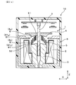
- the present embodiment is an example in which the shape of the fixed core 3 is changed. 12, as shown in FIG. 13, in the present embodiment is formed with the fixed core side projection 8 S to the fixed core 3.
- the fixed core side projection 8 S are prevented from magnetic spring 5 is deformed to the minimum spring length L MIN when the movable core 4 is sucked close position (see FIG. 13).
- the present embodiment is an example in which the shape of the fixed core 3 is modified.
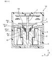
- 14, as shown in FIG. 15, in this embodiment, as in Embodiment 2, is formed with the fixed core side projection 8 S to the fixed core 3.
- it is formed a tapered surface 81 (stationary core side tapered surface 81 S) to the fixed core side projection 8 S.
- Stationary core side tapered surface 81 S when viewed from the Z direction, and is configured to overlap a part of the magnetic spring 5.
- the fixed core 3 is formed with the fixed core side projection 8 S, as in Embodiment 2, when the movable core 4 is sucked close position (see FIG. 15), the magnetic spring 5 Can be more reliably suppressed from being deformed to the minimum spring length L MIN .
- tapered surfaces 81 (stationary core side tapered surface 81 S) is formed on the fixed core side projection 8 S. Therefore as shown in FIG. 14, it can be in the oblique direction to reduce the distance D S between the stationary core side projection 8 S and the magnetic spring 5.
- the present embodiment is an example in which the shape of the fixed core 3 is changed.
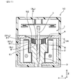
- 16 as shown in FIG. 17, in this embodiment, similarly to Embodiment 3, is formed with the fixed core side projection 8 S to the fixed core 3.
- Tapered surface 81 (stationary core side tapered surface 81 S) is formed in the fixed core side projection 8 S.
- all parts of the magnetic spring 5 is configured so as to overlap the fixed core side tapered surface 81 S.
- Solenoid device 1 of this embodiment when viewed from the Z direction, all parts of the magnetic spring 5 is configured so as to overlap the fixed core side tapered surface 81 S. Therefore, all portions of the magnetic spring 5 can be brought close to the stationary core side tapered surface 81 S. Therefore, it is possible to flux ⁇ tends to flow between the fixed core side tapered surface 81 S and the magnetic spring 5, to increase the attraction force of the movable core 4.
- the other configurations and effects are the same as those of the first embodiment.
- Embodiment 5 is an example in which the shape of the movable core 4 is changed. As shown in FIGS. 18 and 19, in the present embodiment, the movable core side protrusion 8 M is formed on the movable core 4. As shown in FIG. 19, this movable core side projection 8 M, when the movable core 4 is sucked into the approach position, and prevent the magnetic spring 5 is deformed to the minimum spring length L MIN.
- Embodiment 6 is an example in which the shape of the movable core 4 is changed.
- Figure 20 as shown in FIG. 21, in this embodiment, similarly to Embodiment 5, it is formed with the movable core side projection 8 M to the movable core 4.
- a tapered surface 81 (a movable core side tapered surface 81 M ) is formed on the movable core side protrusion 8 M.
- the movable core side tapered surface 81 M is configured to overlap all the portions of the magnetic spring 5 when viewed from the Z direction.
- all parts of the magnetic spring 5 when viewed from the Z direction, all parts of the magnetic spring 5, are configured to overlap with the movable core side tapered surface 81 M. Therefore, as shown in FIG. 20, all parts of the magnetic spring 5 can be close to the movable core side tapered surface 81 M. Therefore, the magnetic flux ⁇ can easily flow between the magnetic spring 5 and the movable core side tapered surface 81 M, and the attraction of the movable core 4 can be increased.
- the other configurations and effects are the same as those of the first embodiment.
- the movable core side tapered surface 81 M is configured to overlap all the portions of the magnetic spring 5 when viewed from the Z direction, but the present disclosure is not limited thereto. That is, when viewed in the Z direction, the movable core side tapered surface 81 M may be configured to overlap with a part of the magnetic spring 5.
- the present embodiment is an example in which the shapes of the fixed core 3 and the movable core 4 are changed. As shown in FIG. 22, in the present embodiment, the protrusions 8 are formed on both the fixed core 3 and the movable core 4.
- the movable core 4 is formed by the projection 8 (fixed core side projection 8 S ) formed on the fixed core 3 and the projection 8 (movable core side projection 8 M ) formed on the movable core 4. Is suppressed from being deformed to the minimum spring length L MIN when the magnetic spring 5 is attracted.
- the fixed core side projection 8 S the tapered surface 81 (stationary core side tapered surface 81 S) is formed. Further, a tapered surface 81 (a movable core side tapered surface 81 M ) is also formed on the movable core side protrusion 8 M. These tapered surfaces 81 are configured to overlap all the portions of the magnetic spring 5 when viewed from the Z direction.
- the protrusions 8 (8 S , 8 M ) are formed on both the fixed core 3 and the movable core 4. Therefore, it is possible to reduce the distance D S between the fixed core 3 and the magnetic spring 5 can be smaller spacing D M of the movable core 4 and the magnetic spring 5. Therefore, the magnetic flux ⁇ can flow more easily, and the attraction of the movable core 4 can be further enhanced.
- the solenoid device 1 of this embodiment when viewed from the Z direction, all parts of the magnetic spring 5 is configured to overlap the fixed core side tapered surface 81 S and the movable core side tapered surface 81 M . Therefore, it is possible to it is possible to approach all the sites of the magnetic spring 5 to the stationary core side tapered surface 81 S, is closer to the movable core side tapered surface 81 M. Therefore, the magnetic flux ⁇ can easily flow between the fixed core side tapered surface 81 S and the magnetic spring 5 and between the magnetic spring 5 and the movable core side tapered surface 81 M, and the attractive force of the movable core 4 can be further enhanced. Can.
- the other configurations and effects are the same as those of the first embodiment.
- the present embodiment is an example in which the shapes of the fixed core 3 and the movable core 4 are changed.
- the protrusions 8 (fixed core side protrusions 8 S , movable core side protrusions 8 M ) of the fixed core 3 and the movable core 4 respectively. Is formed.
- tapered surfaces 81 (a fixed core side tapered surface 81 S and a movable core side tapered surface 81 M ) are formed on the individual projections 8 (8 S , 8 M ). These two tapered surfaces 81 S and 81 M are parallel to each other.
- the two tapered surfaces 81 S and 81 M of the fixed core side tapered surface 81 S and the movable core side tapered surface 81 M are parallel to each other. Therefore, as shown in FIG. 25, definitive when aspiration of the movable core 4, between the fixed core side tapered surface 81 S and the magnetic spring 5 gap, and between the movable core side tapered surface 81 M and the magnetic spring 5 The gaps can be minimized, respectively. Therefore, the movable core 4 can be continuously suctioned with a stronger suction force.
- the other configurations and effects are the same as those of the first embodiment.
- the present embodiment is an example in which the shapes of the fixed core 3 and the movable core 4 and the direction of the magnetic spring 5 are changed.
- the central portion 51 of the magnetic spring 5 is directed to the fixed core 3 side
- the peripheral portion 52 is directed to the movable core 4 side.
- the protrusion 8 is formed in the fixed core 3 and the movable core 4, respectively.
- These projections 8 (8 S , 8 M ) are configured so that the magnetic spring 5 does not deform to the minimum spring length L MIN when the movable core 4 is attracted.
- the stationary core side tapered surface 81 S is formed in the fixed core side projection 8 S, it is formed with the movable core side tapered surface 81 M to the movable core side projection 8 M.
- the tapered surfaces 81 S and 81 M are configured to overlap all the portions of the magnetic spring 5 when viewed in the Z direction.
- the other configurations and effects are the same as those of the first embodiment.
Landscapes
- Physics & Mathematics (AREA)
- Electromagnetism (AREA)
- Engineering & Computer Science (AREA)
- Power Engineering (AREA)
- Electromagnets (AREA)
Abstract
Description
上記電磁コイル内に配された固定コアと、
上記電磁コイルへの通電の有無によって、該電磁コイルの軸方向に進退動作する可動コアと、
上記固定コアと上記可動コアとの間に配され、磁性体からなり、上記可動コアを上記軸方向における上記固定コアから離隔する向きに付勢する磁性ばねと、
該磁性ばねと上記可動コアと上記固定コアと共に、上記磁束が流れる磁気回路を構成するヨークとを備え、
上記可動コアは、上記電磁コイルへ通電したときに、発生した電磁力によって、上記磁性ばねのばね力に抗して、上記固定コアに相対的に近い接近位置まで吸引され、上記電磁コイルへの通電を停止したときに、上記磁性ばねのばね力によって、上記接近位置よりも上記固定コアから離れた離隔位置へ移動し、
上記磁性ばねは、上記磁性体からなる板状ばね部材を、該板状ばね部材の厚さ方向が上記電磁コイルの径方向と一致するように螺旋状に巻回してなり、その中心部が周縁部よりも上記軸方向における一方側に位置しており、
上記可動コアが上記接近位置へ吸引されたときに、上記磁性ばねが、上記軸方向における上記板状ばね部材の幅である最小ばね長まで変形しないよう構成されている、ソレノイド装置である。
そのため、磁性ばねのばね力の製品ばらつきが大きい領域(最小ばね長付近)を使用しなくてすみ、可動コアの吸引力(すなわち、電磁コイルへの通電により発生した電磁力から、磁性ばねのばね力を引いた力)がばらつくことを抑制できる。したがって、上記吸引力が不足して可動コアを吸引できなくなったり、可動コアの吸引速度が大きくばらついたりすることを抑制できる。
上記ソレノイド装置に係る実施形態について、図1~図11を参照して説明する。図1~図3に示すごとく、本形態のソレノイド装置1は、通電により磁束φが発生する電磁コイル2と、固定コア3と、可動コア4と、磁性ばね5と、ヨーク6とを備える。固定コア3は、電磁コイル2内に配されている。可動コア4は、電磁コイル2への通電の有無によって、電磁コイル2の軸方向(Z方向)に進退動作する。
そのため、磁性ばね5のばね力の製品ばらつきが大きい領域(最小ばね長LMIN付近:図6参照)を使用しなくてすみ、可動コア4の吸引力(すなわち、電磁コイル2への通電により発生した電磁力から、磁性ばね5のばね力を引いた力)が不足して可動コア4を吸引できなくなったり、可動コア4の吸引速度が大きくばらついたりすることを抑制できる。
このような構造の磁性ばね5を用いると、磁性ばね5の断面積を大きくしやすい。そのため、磁性ばね5に多くの磁束φを流すことができ、可動コア4の吸引力を高めることができる。また、磁性ばね5と固定コア3との接触面積、及び磁性ばね5と可動コア4との接触面積を、それぞれ大きくしやすい。そのため、流れる磁束φの量をより多くすることができ、可動コア4の吸引力をより高めることができる。また、上記構造の磁性ばね5を用いると、可動コア4が吸引されるに従って、磁性ばね5と固定コア3との接触面積、及び磁性ばね5と可動コア4との接触面積を、次第に増加させることができる。したがって、可動コア4が固定コア3に接近し、磁性ばね5のばね力が増加しても、流れる磁束φの量が多くなるため、電磁コイル2の電磁力を増やすことができ、可動コア4を強い力で吸引することができる。
本形態は、固定コア3の形状を変更した例である。図12、図13に示すごとく、本形態では固定コア3に固定コア側突部8Sを形成してある。この固定コア側突部8Sにより、可動コア4が接近位置(図13参照)へ吸引されたときに磁性ばね5が最小ばね長LMINまで変形することを抑制している。
その他、実施形態1と同様の構成および作用効果を備える。
本形態は、固定コア3の形状を変形した例である。図14、図15に示すごとく、本形態では、実施形態2と同様に、固定コア3に固定コア側突部8Sを形成してある。本形態では、この固定コア側突部8Sにテーパ面81(固定コア側テーパ面81S)を形成してある。固定コア側テーパ面81Sは、Z方向から見たときに、磁性ばね5の一部と重なるよう構成されている。
その他、実施形態1と同様の構成および作用効果を備える。
本形態は、固定コア3の形状を変更した例である。図16、図17に示すごとく、本形態では、実施形態3と同様に、固定コア3に固定コア側突部8Sを形成してある。この固定コア側突部8Sにはテーパ面81(固定コア側テーパ面81S)が形成されている。本形態では、Z方向から見たときに、磁性ばね5の全ての部位が、固定コア側テーパ面81Sと重なるよう構成されている。
その他、実施形態1と同様の構成及び作用効果を備える。
本形態は、可動コア4の形状を変更した例である。図18、図19に示すごとく、本形態では、可動コア4に可動コア側突部8Mを形成してある。図19に示すごとく、この可動コア側突部8Mにより、可動コア4が接近位置へ吸引されたときに、磁性ばね5が最小ばね長LMINまで変形することを抑制している。
その他、実施形態1と同様の構成および作用効果を備える。
本形態は、可動コア4の形状を変更した例である。図20、図21に示すごとく、本形態では、実施形態5と同様に、可動コア4に可動コア側突部8Mを形成してある。また、本形態では、可動コア側突部8Mにテーパ面81(可動コア側テーパ面81M)を形成してある。この可動コア側テーパ面81Mは、Z方向から見たときに、磁性ばね5の全ての部位と重なるよう構成されている。
そのため、図20に示すごとく、磁性ばね5の全ての部位を、可動コア側テーパ面81Mに接近させることができる。したがって、磁束φが磁性ばね5と可動コア側テーパ面81Mとの間を流れやすくなり、可動コア4の吸引力を高くすることができる。
その他、実施形態1と同様の構成および作用効果を備える。
本形態は、固定コア3及び可動コア4の形状を変更した例である。図22に示すごとく、本形態では、固定コア3と可動コア4との双方に、突部8を形成してある。
そのため、固定コア3と磁性ばね5との間隔DSを狭くすることができると共に、可動コア4と磁性ばね5との間隔DMをも狭くすることができる。したがって、磁束φがより流れやすくなり、可動コア4の吸引力をより高めることができる。
そのため、磁性ばね5の全ての部位を固定コア側テーパ面81Sに接近させることができると共に、可動コア側テーパ面81Mにも接近させることができる。したがって、磁束φが固定コア側テーパ面81Sと磁性ばね5との間、及び磁性ばね5と可動コア側テーパ面81Mとの間を流れやすくなり、可動コア4の吸引力をより高めることができる。
その他、実施形態1と同様の構成および作用効果を備える。
本形態は、固定コア3と可動コア4の形状を変更した例である。図24、図25に示すごとく、本形態では、実施形態7と同様に、固定コア3と可動コア4とにそれぞれ突部8(固定コア側突部8S、可動コア側突部8M)を形成してある。また、個々の突部8(8S,8M)にテーパ面81(固定コア側テーパ面81S,可動コア側テーパ面81M)を形成してある。これら2つのテーパ面81S,81Mは互いに平行である。
そのため、図25に示すごとく、可動コア4を吸引したときにおける、固定コア側テーパ面81Sと磁性ばね5との間の隙間、および可動コア側テーパ面81Mと磁性ばね5との間の隙間を、それぞれ最小にすることができる。したがって、より強い吸引力で、可動コア4を吸引し続けることができる。
その他、実施形態1と同様の構成および作用効果を備える。
本形態は、固定コア3及び可動コア4の形状と、磁性ばね5の向きとを変更した例である。図26、図27に示すごとく、本形態では、磁性ばね5の中心部51を固定コア3側に向け、周縁部52を可動コア4側に向けてある。また、固定コア3と可動コア4とに、それぞれ突部8を形成してある。これらの突部8(8S,8M)によって、可動コア4が吸引されたときに、磁性ばね5が最小ばね長LMINまで変形しないよう構成してある。
その他、実施形態1と同様の構成および作用効果を備える。
Claims (9)
- 通電により磁束(φ)が発生する電磁コイル(2)と、
上記電磁コイル内に配された固定コア(3)と、
上記電磁コイルへの通電の有無によって、該電磁コイルの軸方向(Z)に進退動作する可動コア(4)と、
上記固定コアと上記可動コアとの間に配され、磁性体からなり、上記可動コアを上記軸方向における上記固定コアから離隔する向きに付勢する磁性ばね(5)と、
該磁性ばねと上記可動コアと上記固定コアと共に、上記磁束が流れる磁気回路(C)を構成するヨーク(6)とを備え、
上記可動コアは、上記電磁コイルへ通電したときに、発生した電磁力によって、上記磁性ばねのばね力に抗して、上記固定コアに相対的に近い接近位置まで吸引され、上記電磁コイルへの通電を停止したときに、上記磁性ばねのばね力によって、上記接近位置よりも上記固定コアから離れた離隔位置へ移動し、
上記磁性ばねは、上記磁性体からなる板状ばね部材(50)を、該板状ばね部材の厚さ方向が上記電磁コイルの径方向と一致するように螺旋状に巻回してなり、その中心部(51)が周縁部(52)よりも上記軸方向における一方側に位置しており、
上記可動コアが上記接近位置へ吸引されたときに、上記磁性ばねが、上記軸方向における上記板状ばね部材の幅である最小ばね長(LMIN)まで変形しないよう構成されている、ソレノイド装置(1)。 - 上記固定コアには、該固定コアから上記軸方向における上記可動コア側へ突出し、該可動コアが上記接近位置へ吸引されたときに上記磁性ばねが上記最小ばね長まで変形することを抑制する固定コア側突部(8S)が形成されている、請求項1に記載のソレノイド装置。
- 上記固定コア側突部には、上記軸方向から見たときに上記磁性ばねの少なくとも一部と重なる固定コア側テーパ面(81S)が形成されている、請求項2に記載のソレノイド装置。
- 上記軸方向から見たときに、上記磁性ばねの全ての部位が上記固定コア側テーパ面と重なるよう構成されている、請求項3に記載のソレノイド装置。
- 上記可動コアには、該可動コアから上記軸方向における上記固定コア側へ突出し、上記可動コアが上記接近位置へ吸引されたときに上記磁性ばねが上記最小ばね長まで変形することを抑制する可動コア側突部(8M)が形成されている、請求項1~4のいずれか一項に記載のソレノイド装置。
- 上記可動コア側突部には、上記軸方向から見たときに上記磁性ばねの少なくとも一部と重なる可動コア側テーパ面(81M)が形成されている、請求項5に記載のソレノイド装置。
- 上記軸方向から見たときに、上記磁性ばねの全ての部位が上記可動コア側テーパ面と重なるよう構成されている、請求項6に記載のソレノイド装置。
- 上記固定コアに、上記可動コアが上記接近位置へ吸引されたときに上記磁性ばねが上記最小ばね長まで変形することを抑制する固定コア側突部が形成され、かつ、上記可動コアに、該可動コアが上記接近位置へ吸引されたときに上記磁性ばねが上記最小ばね長まで変形することを抑制する可動コア側突部が形成されている、請求項1~7のいずれか一項に記載のソレノイド装置。
- 上記固定コア側突部と上記可動コア側突部とには、上記軸方向から見たときに上記磁性ばねの少なくとも一部と重なるテーパ面(81S,81M)がそれぞれ形成され、これら2つの上記テーパ面は互いに平行である、請求項8に記載のソレノイド装置。
Priority Applications (3)
| Application Number | Priority Date | Filing Date | Title |
|---|---|---|---|
| CN201880072136.XA CN111542902B (zh) | 2017-11-09 | 2018-11-08 | 螺线管装置 |
| DE112018005434.9T DE112018005434B4 (de) | 2017-11-09 | 2018-11-08 | Solenoidvorrichtung |
| US16/871,332 US11335490B2 (en) | 2017-11-09 | 2020-05-11 | Solenoid device |
Applications Claiming Priority (2)
| Application Number | Priority Date | Filing Date | Title |
|---|---|---|---|
| JP2017-216193 | 2017-11-09 | ||
| JP2017216193A JP6798755B2 (ja) | 2017-11-09 | 2017-11-09 | ソレノイド装置 |
Related Child Applications (1)
| Application Number | Title | Priority Date | Filing Date |
|---|---|---|---|
| US16/871,332 Continuation US11335490B2 (en) | 2017-11-09 | 2020-05-11 | Solenoid device |
Publications (1)
| Publication Number | Publication Date |
|---|---|
| WO2019093402A1 true WO2019093402A1 (ja) | 2019-05-16 |
Family
ID=66439202
Family Applications (1)
| Application Number | Title | Priority Date | Filing Date |
|---|---|---|---|
| PCT/JP2018/041422 Ceased WO2019093402A1 (ja) | 2017-11-09 | 2018-11-08 | ソレノイド装置 |
Country Status (5)
| Country | Link |
|---|---|
| US (1) | US11335490B2 (ja) |
| JP (1) | JP6798755B2 (ja) |
| CN (1) | CN111542902B (ja) |
| DE (1) | DE112018005434B4 (ja) |
| WO (1) | WO2019093402A1 (ja) |
Families Citing this family (1)
| Publication number | Priority date | Publication date | Assignee | Title |
|---|---|---|---|---|
| JP6798755B2 (ja) * | 2017-11-09 | 2020-12-09 | 株式会社Soken | ソレノイド装置 |
Citations (5)
| Publication number | Priority date | Publication date | Assignee | Title |
|---|---|---|---|---|
| JP2003083464A (ja) * | 2001-09-10 | 2003-03-19 | Mitsubishi Electric Corp | 電磁弁 |
| JP2003217420A (ja) * | 2002-01-18 | 2003-07-31 | Denso Corp | マグネットスイッチ |
| JP2010527507A (ja) * | 2007-04-27 | 2010-08-12 | エドワーズ株式会社 | プレート回転装置、排気路開閉度変更装置、被排気装置、搬送装置、ビーム装置、及び、ゲートバルブ |
| JP2016070435A (ja) * | 2014-09-30 | 2016-05-09 | 株式会社日本自動車部品総合研究所 | 電磁アクチュエータおよびこの電磁アクチュエータを用いた電磁弁 |
| JP2018142529A (ja) * | 2017-02-28 | 2018-09-13 | 株式会社Soken | 電磁継電器 |
Family Cites Families (16)
| Publication number | Priority date | Publication date | Assignee | Title |
|---|---|---|---|---|
| DE20114466U1 (de) * | 2001-09-01 | 2002-01-03 | Eto Magnetic Kg | Elektromagnetische Stellvorrichtung |
| CN101504047A (zh) * | 2009-03-20 | 2009-08-12 | 扬州弹簧有限公司 | 圆柱钢板宝塔弹簧及其制造方法 |
| DE102009030479B4 (de) * | 2009-06-24 | 2011-04-28 | Saia-Burgess Dresden Gmbh | Magnetauslöser |
| JP5581973B2 (ja) * | 2010-10-28 | 2014-09-03 | 株式会社デンソー | 電磁ソレノイド |
| DE102011077069A1 (de) * | 2011-06-07 | 2012-12-13 | Robert Bosch Gmbh | Elektromagnetisch betätigbares Ventil |
| DE102012107281B4 (de) * | 2012-08-08 | 2014-03-06 | Eto Magnetic Gmbh | Bistabile elektromagnetische Stellvorrichtung, Ankerbaugruppe sowie Nockenwellenverstellvorrichtung |
| DE102013218854A1 (de) * | 2013-09-19 | 2015-03-19 | Robert Bosch Gmbh | Elektromagnetisch ansteuerbares Saugventil |
| JP6329781B2 (ja) | 2014-02-27 | 2018-05-23 | 株式会社Soken | ソレノイド装置 |
| DE102014109124B4 (de) * | 2014-06-30 | 2016-05-19 | Kendrion (Villingen) Gmbh | Elektromagnetische Nockenwellenverstelleinrichtung |
| DE112017005582T5 (de) * | 2016-11-04 | 2019-08-29 | Anden Co., Ltd. | Elektromagnetisches Relais |
| WO2018084222A1 (ja) * | 2016-11-04 | 2018-05-11 | 株式会社デンソー | 電磁継電器 |
| JP6485465B2 (ja) * | 2017-01-18 | 2019-03-20 | アンデン株式会社 | 接点装置及び電磁継電器 |
| US10535483B2 (en) * | 2017-02-28 | 2020-01-14 | Soken, Inc. | Electromagnetic relay device |
| JP6798755B2 (ja) * | 2017-11-09 | 2020-12-09 | 株式会社Soken | ソレノイド装置 |
| JP6984517B2 (ja) * | 2018-03-26 | 2021-12-22 | 株式会社デンソーエレクトロニクス | 電磁継電器 |
| JP7035879B2 (ja) * | 2018-07-24 | 2022-03-15 | 株式会社Soken | 接点装置および電磁継電器 |
-
2017
- 2017-11-09 JP JP2017216193A patent/JP6798755B2/ja active Active
-
2018
- 2018-11-08 DE DE112018005434.9T patent/DE112018005434B4/de active Active
- 2018-11-08 CN CN201880072136.XA patent/CN111542902B/zh active Active
- 2018-11-08 WO PCT/JP2018/041422 patent/WO2019093402A1/ja not_active Ceased
-
2020
- 2020-05-11 US US16/871,332 patent/US11335490B2/en active Active
Patent Citations (5)
| Publication number | Priority date | Publication date | Assignee | Title |
|---|---|---|---|---|
| JP2003083464A (ja) * | 2001-09-10 | 2003-03-19 | Mitsubishi Electric Corp | 電磁弁 |
| JP2003217420A (ja) * | 2002-01-18 | 2003-07-31 | Denso Corp | マグネットスイッチ |
| JP2010527507A (ja) * | 2007-04-27 | 2010-08-12 | エドワーズ株式会社 | プレート回転装置、排気路開閉度変更装置、被排気装置、搬送装置、ビーム装置、及び、ゲートバルブ |
| JP2016070435A (ja) * | 2014-09-30 | 2016-05-09 | 株式会社日本自動車部品総合研究所 | 電磁アクチュエータおよびこの電磁アクチュエータを用いた電磁弁 |
| JP2018142529A (ja) * | 2017-02-28 | 2018-09-13 | 株式会社Soken | 電磁継電器 |
Also Published As
| Publication number | Publication date |
|---|---|
| CN111542902A (zh) | 2020-08-14 |
| DE112018005434T5 (de) | 2020-11-05 |
| JP6798755B2 (ja) | 2020-12-09 |
| JP2019087683A (ja) | 2019-06-06 |
| US11335490B2 (en) | 2022-05-17 |
| CN111542902B (zh) | 2021-11-16 |
| US20200273615A1 (en) | 2020-08-27 |
| DE112018005434B4 (de) | 2026-01-08 |
Similar Documents
| Publication | Publication Date | Title |
|---|---|---|
| JP5581973B2 (ja) | 電磁ソレノイド | |
| WO2015015761A1 (ja) | 電磁継電器 | |
| KR101480963B1 (ko) | 전자 개폐기 | |
| CN105531788B (zh) | 电磁继电器 | |
| CN102612728B (zh) | 用于电开关的磁助螺线管 | |
| JP6236326B2 (ja) | ソレノイド装置、およびソレノイド制御システム | |
| JP6027860B2 (ja) | ソレノイド装置、及びその動作方法 | |
| CN109952628A (zh) | 电磁继电器 | |
| CN107004489A (zh) | 螺线管 | |
| CN111344829B (zh) | 起动器用电磁开关装置 | |
| WO2019093402A1 (ja) | ソレノイド装置 | |
| JP4577290B2 (ja) | 電磁継電器 | |
| JP6664978B2 (ja) | 電磁継電器 | |
| JP5982266B2 (ja) | ソレノイド装置 | |
| JP5884777B2 (ja) | リニアソレノイド | |
| JP7022596B2 (ja) | 電磁継電器 | |
| CN108475604A (zh) | 继电器设备 | |
| JP6447402B2 (ja) | リニアソレノイド | |
| JP6468988B2 (ja) | ソレノイド装置及びソレノイドシステム | |
| JP6933060B2 (ja) | 電磁継電器 | |
| CN105849847A (zh) | 磁性开关以及具有该磁性开关的起动机 | |
| JP2014239239A (ja) | 電磁ソレノイド | |
| JP6027951B2 (ja) | ソレノイド装置 | |
| JP2020092115A (ja) | 電磁ソレノイド | |
| JP2020107709A (ja) | ソレノイド装置 |
Legal Events
| Date | Code | Title | Description |
|---|---|---|---|
| 121 | Ep: the epo has been informed by wipo that ep was designated in this application |
Ref document number: 18875780 Country of ref document: EP Kind code of ref document: A1 |
|
| WWE | Wipo information: entry into national phase |
Ref document number: 112018005434 Country of ref document: DE |
|
| WWP | Wipo information: published in national office |
Ref document number: 112018005434 Country of ref document: DE |
|
| 122 | Ep: pct application non-entry in european phase |
Ref document number: 18875780 Country of ref document: EP Kind code of ref document: A1 |
|
| WWG | Wipo information: grant in national office |
Ref document number: 112018005434 Country of ref document: DE |