WO2019085481A1 - 一种曲面显示屏的组立方法及曲面显示屏 - Google Patents
一种曲面显示屏的组立方法及曲面显示屏 Download PDFInfo
- Publication number
- WO2019085481A1 WO2019085481A1 PCT/CN2018/090434 CN2018090434W WO2019085481A1 WO 2019085481 A1 WO2019085481 A1 WO 2019085481A1 CN 2018090434 W CN2018090434 W CN 2018090434W WO 2019085481 A1 WO2019085481 A1 WO 2019085481A1
- Authority
- WO
- WIPO (PCT)
- Prior art keywords
- flexible
- display panel
- glass
- curved
- display screen
- Prior art date
- Legal status (The legal status is an assumption and is not a legal conclusion. Google has not performed a legal analysis and makes no representation as to the accuracy of the status listed.)
- Ceased
Links
Images


Classifications
-
- H—ELECTRICITY
- H10—SEMICONDUCTOR DEVICES; ELECTRIC SOLID-STATE DEVICES NOT OTHERWISE PROVIDED FOR
- H10K—ORGANIC ELECTRIC SOLID-STATE DEVICES
- H10K77/00—Constructional details of devices covered by this subclass and not covered by groups H10K10/80, H10K30/80, H10K50/80 or H10K59/80
- H10K77/10—Substrates, e.g. flexible substrates
- H10K77/111—Flexible substrates
-
- G—PHYSICS
- G06—COMPUTING OR CALCULATING; COUNTING
- G06F—ELECTRIC DIGITAL DATA PROCESSING
- G06F1/00—Details not covered by groups G06F3/00 - G06F13/00 and G06F21/00
- G06F1/16—Constructional details or arrangements
- G06F1/1613—Constructional details or arrangements for portable computers
- G06F1/1633—Constructional details or arrangements of portable computers not specific to the type of enclosures covered by groups G06F1/1615 - G06F1/1626
- G06F1/1637—Details related to the display arrangement, including those related to the mounting of the display in the housing
- G06F1/1652—Details related to the display arrangement, including those related to the mounting of the display in the housing the display being flexible, e.g. mimicking a sheet of paper, or rollable
-
- G—PHYSICS
- G09—EDUCATION; CRYPTOGRAPHY; DISPLAY; ADVERTISING; SEALS
- G09F—DISPLAYING; ADVERTISING; SIGNS; LABELS OR NAME-PLATES; SEALS
- G09F9/00—Indicating arrangements for variable information in which the information is built-up on a support by selection or combination of individual elements
- G09F9/30—Indicating arrangements for variable information in which the information is built-up on a support by selection or combination of individual elements in which the desired character or characters are formed by combining individual elements
- G09F9/301—Indicating arrangements for variable information in which the information is built-up on a support by selection or combination of individual elements in which the desired character or characters are formed by combining individual elements flexible foldable or roll-able electronic displays, e.g. thin LCD, OLED
-
- H—ELECTRICITY
- H10—SEMICONDUCTOR DEVICES; ELECTRIC SOLID-STATE DEVICES NOT OTHERWISE PROVIDED FOR
- H10K—ORGANIC ELECTRIC SOLID-STATE DEVICES
- H10K50/00—Organic light-emitting devices
- H10K50/80—Constructional details
- H10K50/84—Passivation; Containers; Encapsulations
-
- H—ELECTRICITY
- H10—SEMICONDUCTOR DEVICES; ELECTRIC SOLID-STATE DEVICES NOT OTHERWISE PROVIDED FOR
- H10K—ORGANIC ELECTRIC SOLID-STATE DEVICES
- H10K59/00—Integrated devices, or assemblies of multiple devices, comprising at least one organic light-emitting element covered by group H10K50/00
- H10K59/80—Constructional details
- H10K59/87—Passivation; Containers; Encapsulations
- H10K59/871—Self-supporting sealing arrangements
- H10K59/8722—Peripheral sealing arrangements, e.g. adhesives, sealants
-
- H—ELECTRICITY
- H10—SEMICONDUCTOR DEVICES; ELECTRIC SOLID-STATE DEVICES NOT OTHERWISE PROVIDED FOR
- H10K—ORGANIC ELECTRIC SOLID-STATE DEVICES
- H10K2102/00—Constructional details relating to the organic devices covered by this subclass
- H10K2102/301—Details of OLEDs
- H10K2102/311—Flexible OLED
-
- H—ELECTRICITY
- H10—SEMICONDUCTOR DEVICES; ELECTRIC SOLID-STATE DEVICES NOT OTHERWISE PROVIDED FOR
- H10K—ORGANIC ELECTRIC SOLID-STATE DEVICES
- H10K59/00—Integrated devices, or assemblies of multiple devices, comprising at least one organic light-emitting element covered by group H10K50/00
- H10K59/10—OLED displays
- H10K59/12—Active-matrix OLED [AMOLED] displays
-
- H—ELECTRICITY
- H10—SEMICONDUCTOR DEVICES; ELECTRIC SOLID-STATE DEVICES NOT OTHERWISE PROVIDED FOR
- H10K—ORGANIC ELECTRIC SOLID-STATE DEVICES
- H10K59/00—Integrated devices, or assemblies of multiple devices, comprising at least one organic light-emitting element covered by group H10K50/00
- H10K59/10—OLED displays
- H10K59/12—Active-matrix OLED [AMOLED] displays
- H10K59/131—Interconnections, e.g. wiring lines or terminals
-
- Y—GENERAL TAGGING OF NEW TECHNOLOGICAL DEVELOPMENTS; GENERAL TAGGING OF CROSS-SECTIONAL TECHNOLOGIES SPANNING OVER SEVERAL SECTIONS OF THE IPC; TECHNICAL SUBJECTS COVERED BY FORMER USPC CROSS-REFERENCE ART COLLECTIONS [XRACs] AND DIGESTS
- Y02—TECHNOLOGIES OR APPLICATIONS FOR MITIGATION OR ADAPTATION AGAINST CLIMATE CHANGE
- Y02E—REDUCTION OF GREENHOUSE GAS [GHG] EMISSIONS, RELATED TO ENERGY GENERATION, TRANSMISSION OR DISTRIBUTION
- Y02E10/00—Energy generation through renewable energy sources
- Y02E10/50—Photovoltaic [PV] energy
- Y02E10/549—Organic PV cells
Definitions
- the invention relates to the technical field of curved display screens, in particular to a method for assembling a curved display screen and a curved display screen.
- the curved display usually includes the formed protective glass and flexible display panel stacked on top of each other.
- the common curved display is mainly divided into 2.5D display and 3D display. The difference between these two types of curved display is only to protect the glass. Different shapes.
- the 2.5D display refers to a curved display with a flat surface in the middle and a curved surface in the periphery;
- a 3D display refers to a curved display with curved surfaces in the middle and the periphery.
- the final part of the preparation process is the assembly, that is, the flexible display panel and the protective glass are assembled to form a whole.
- the assembly process of the existing curved display screen mainly adopts a curved surface bonding process, which specifically includes: firstly, a curved surface fitting fixture adapted to the shape of the protective glass is respectively used to hold the protective glass and the flexible display panel; and then on the flexible display panel The surface is coated with optical glue; then the flexible display panel coated with the optical glue is pushed up by the curved bonding fixture, and the protective glass is laminated thereon to form a curved display panel; finally, a border is installed around the curved display panel. Form a curved display.
- the embodiments of the present invention are directed to providing a method for assembling a curved display screen and a curved display screen to solve the problem of difficulty in fitting the curved display screen during assembly.
- An embodiment of the present invention provides a method for assembling a curved display screen, comprising: bonding a flexible display panel and a flexible glass; and integrally forming the flexible display panel and the flexible glass after being attached to the frame, the frame surrounding the flexible display
- the process of bonding the flexible display panel and the flexible glass is performed by a press screen bonding method or a rolling transport bonding method.
- mounting the integral formed after the flexible display panel and the flexible glass are bonded into the bezel includes integrally forming the integrated embedding frame formed by bonding the flexible display panel and the flexible glass.
- mounting the integral formed after the flexible display panel and the flexible glass are bonded into the bezel includes attaching the bezel frame to the entire perimeter formed by the flexible display panel and the flexible glass.
- the inner surface of the bezel includes an annular groove in the circumferential direction, and the integral periphery formed by the flexible display panel and the flexible glass is embedded in the annular groove.
- bonding the flexible display panel and the flexible glass to form a unit comprises: horizontally holding the flexible display panel by using a rolling transport bonding device; applying glue on the flexible display panel; and rolling the flexible glass onto the glue.
- integrally mounting the flexible display panel and the flexible glass after being assembled into the bezel includes: affixing a curved border of the entire peripheral frame after the flexible display panel and the flexible glass are attached.
- the groove has a depth of 3-5 mm.
- the cross-sectional shape of the annular groove is curved, or U-shaped.
- the invention also provides a curved display screen, comprising a flexible display panel; flexible glass, the flexible display panel and the flexible glass are stacked on top and bottom to form a whole; and the frame, the perimeter of the frame is smaller than the whole formed by the flexible display panel and the flexible glass The perimeter.
- the inner surface of the bezel includes an annular groove in the circumferential direction.
- the annular groove has a curved or U-shaped cross-sectional shape.
- the annular groove has a depth of 3-5 mm.
- the method for assembling a curved display screen and the curved display screen replaces the formed curved glass in the prior art with the flexible display panel by using flexible glass, and then the whole after the bonding
- the perimeter of the perimeter is assembled, wherein the perimeter of the border is smaller than the overall length of the border after the fit, thus forming a curved display.
- the essence of the method for assembling a curved display screen according to the present invention is to replace the curved surface fitting with a soft-soft planar bonding, so that the uniformity of the flexible display panel during the bonding process is improved, thereby reducing the process of assembling the curved display screen.
- the difficulty of fitting is to replace the curved surface fitting with a soft-soft planar bonding, so that the uniformity of the flexible display panel during the bonding process is improved, thereby reducing the process of assembling the curved display screen.
- FIG. 1 is a flow chart of a method for assembling a curved display screen according to an embodiment of the present invention.
- FIGS. 2a-2d are schematic diagrams showing the assembly process of a curved display screen according to an embodiment of the present invention.
- FIG. 3 is a schematic structural diagram of a display panel according to an embodiment of the present invention.
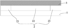
- FIG. 4 is a schematic structural diagram of an OLED module according to an embodiment of the present invention.
- FIG. 1 is a flow chart of a method for assembling a curved display screen according to an embodiment of the present invention.
- the curved display screen comprises a flexible display panel stacked on top and bottom and a flexible glass, and a frame surrounding the periphery of the flexible display panel and the flexible glass.
- the method 100 of assembling the curved display comprises:
- step S10 the flexible display panel and the flexible glass are attached.
- the bonding of the flexible display panel and the flexible glass can be realized by using the existing soft-soft-soft bonding device, and the essence thereof is a flat fit.
- Common soft-to-soft-surface bonding methods mainly include pressure-screen fitting and rolling transmission bonding.
- Press-screen bonding refers to placing the flexible display panel horizontally, pressing the flexible glass surface over the flexible display panel; and rolling transmission Fitting means placing the flexible display panel horizontally, and rolling the flexible glass from one side to the top of the flexible display panel through the roller. Since the rolling transfer bonding is smaller than the pressure screen bonding, the single bonding area is small, the force can be balanced, wrinkles are avoided, and the number of bubbles generated is effectively reduced. Therefore, the present invention preferably uses a rolling transport fit.
- Ultra-thin flexible glass has bendable properties. After testing, the flexible glass can withstand 100,000 bending fatigue tests with a bending radius of 5 mm. When the glass is thin to a certain extent, the softness of the glass is exhibited and it can be bent without breaking. Ultra-thin flexible glass has the relatively stable mechanical and chemical properties of glass, hardness, transparency, heat resistance, electrical insulation, gas impermeability, and oxidation and light environment, and is flexible and lightweight.
- a flexible display panel refers to a bendable substrate having a display function.
- the flexible display panel is an AMOLED (Active Matrix Organic Light Emitting Diode) panel.
- step S20 the whole of the flexible display panel and the flexible glass are mounted in a frame, and the frame surrounds the entire periphery formed by the flexible display panel and the flexible glass.
- the perimeter of the frame is smaller than the flexible display panel and the flexible glass sticker.
- the whole after the flexible display panel and the flexible glass are bonded is a plane having a bendable property, and when the whole is mounted to a frame having a circumference smaller than the whole, the whole is curved into a curved surface by a plane.
- mounting the flexible display panel and the flexible glass together into the bezel includes integrally inserting the flexible display panel and the flexible glass into the bezel.
- the embedding here refers to the overall bendability after the flexible display panel and the flexible glass are bonded, and the whole is like a mounting glass, and then the outer circumference of the frame is smaller than that of the flexible display panel and the flexible glass. This feature of the overall perimeter entraps the whole body in the frame.
- mounting the entirety of the flexible display panel and the flexible glass into the bezel includes attaching the bezel frame to the entire perimeter of the flexible display panel and the flexible glass.
- the frame label refers to coating an OVA (Optically Clear Adhesive) optical glue between the flexible display panel and the flexible glass or bonding the flexible display panel and the flexible glass together using a double-sided tape.
- OVA Optically Clear Adhesive
- a circumferential groove in the circumferential direction may be provided on the inner surface of the bezel, and the flexible display panel and the flexible glass are formed after being bonded.
- the entire perimeter is embedded in the annular groove.
- the inner surface of the bezel refers to a surface that faces the inside of the bezel.
- the depth of the annular groove is preferably 3-5 mm, which ensures that the mounting is secure and does not make the frame too thick.
- the width of the annular groove is equal to the sum of the thicknesses of the flexible display panel and the flexible glass.
- the shape of the cross section of the annular groove may be U-shaped or curved.
- the method 100 of assembling the curved display shown in FIG. 1 will now be described by way of a specific embodiment.
- FIGS. 2a-2d are schematic diagrams showing the assembly process of a curved display screen according to an embodiment of the present invention.
- the assembly process of the curved display screen includes: referring to step S10, the flexible display panel 201 is horizontally held by the rolling transfer bonding device, as shown in FIG. 2a; the OCA adhesive 202 is coated on the flexible display panel 201, as shown in FIG. 2b. Rolling the flexible glass 203 onto the OCA adhesive 202, as shown in FIG. 2c; referring to step S20, the entire peripheral frame after the flexible display panel 201 and the flexible glass 202 are attached to the curved border 204 (ie, The border of the curved groove), as shown in Figure 2d.
- the curved border 204 ie, The border of the curved groove
- a flexible glass is used instead of the formed curved glass in the prior art to planarly fit the flexible display panel to form a bendable whole body, and the bendable property is utilized.
- the flexible display panel and the flexible glass are combined with the whole body and the frame. Since the perimeter of the frame is smaller than the overall circumference of the flexible display panel and the flexible glass after bonding, a curved display screen is formed.
- the assembly method replaces the surface fitting by the planar fitting, so that the screen body distribution is more uniform during the fitting process, the bubble generation is effectively reduced, and the fitting difficulty in the process of assembling the curved display screen is reduced.
- the existing soft-soft-soft-surface bonding equipment can realize the assembly of the curved display screen and save cost.
- the invention also provides a curved display screen, the cross-sectional structure of which is shown in Figure 2d.
- the curved display screen comprises a flexible display panel 201, a flexible glass 203 and a bezel 204, wherein the flexible display panel 201 and the flexible glass 203 are integrally stacked on top and bottom, and the bezel 204 surrounds the flexible display panel 201 and The periphery of the flexible glass 203 is formed, and the circumference of the bezel 204 is smaller than the circumference of the whole.
- the perimeter of the bezel 204 refers to the maximum distance traveled by one round from the inner surface of the bezel 204.
- the inner surface of the bezel 204 includes an annular groove 205 in the circumferential direction.
- the depth D of the annular groove 205 is preferably 3-5 mm, which ensures that the mounting is secure and does not make the frame 204 too thick.
- the width of the annular groove 205 is equal to the sum of the thicknesses of the flexible display panel 201 and the flexible glass 203.
- the cross-sectional shape of the annular groove 205 may be U-shaped or curved.
- FIG. 3 is a schematic structural diagram of a display panel according to an embodiment of the present invention.
- the display panel includes a substrate 1a, an OLED module 2a disposed on a first surface of the substrate 1a, and a wiring region 3a disposed on a second surface of the substrate 1a, wherein the second surface is a surface opposite to the first surface
- the routing area 3a is electrically connected to the OLED module 2a of the first surface.
- the routing area of the non-display portion is disposed on the back surface of the substrate, so that the OLED module is electrically connected to the front surface of the OLED module to complete the routing function, and the front surface of the display device is greatly reduced.
- the area of the display area enables the device to achieve a narrow border or even a full screen display, thereby enhancing the display effect of the screen and improving the user's visual experience.
- the substrate 1a includes vias, and the circuit traces of the trace regions 3a can be connected to the OLED module 2a on the front side via vias on the substrate 1a.
- the via structure may be set in one-to-one correspondence with the circuit traces, or one via may be corresponding to a plurality of circuit traces, or one via may correspond to all circuit traces.
- the holes may be punched by a laser or chemically, and the walls of the holes may be vapor-deposited with various conductive media such as copper.
- the circuit traces of the rear trace region 3 of the substrate 1a can be electrically connected to the front OLED module 2a through the via holes.
- FIG. 4 is a schematic structural diagram of an OLED module according to an embodiment of the present invention.
- the OLED module includes a stacked first module material layer 1 and a second module material layer 3; and at least one disposed between the first module material layer 1 and the second module material layer 3
- the strain barrier layer 2 ; wherein the strain barrier layer 2 comprises a chamber 22 and an elastic material layer 21 surrounding the periphery of the chamber.
- the module material layer is a functional unit constituting the flexible display module, and each module material layer may be composed of a plurality of functional layers.
- the module material layer may be a flexible display body, a touch layer, and a polarizer layer.
- the first and second qualifiers are introduced in the embodiment of the present invention, such as A module material layer 1 and a second module material layer 3 and the like.
- a strain barrier layer 2 is disposed between the first module material layer 1 and the second module material layer 3. Since the strain barrier layer 2 can effectively block the strain of the first module material layer 1 and the second module material layer 3, the first module material layer 1 and the second module material can be effectively prevented from occurring when the bending deformation occurs. The transmission of the strain between the layers 3 reduces the strain of the first module material layer 1 and the second module material layer 3, thereby significantly improving the bending resistance of the flexible display module and improving the reliability of the product.
- the OLED module provided by the embodiment of the present invention is not limited to including only the first module material layer 1 and the second module material layer 3 shown in FIG. 1 , and may also include more layers of module materials.
- a strain barrier layer 2 may be disposed between adjacent two layers of module material layers. The embodiment of the present invention does not specifically limit the number of layers of the module material layer and the adjacent barrier material layers 2 between the module material layers.
- the chamber 22 may be filled with a gas or a vacuum, and may function to block strain. However, when the chamber 22 is filled with gas, the air pressure inside and outside the chamber 22 may be balanced.
- the gas may be a mixture of one or more of air or an inert gas.
- the air resources are abundant and convenient to collect, and the air filled in the chamber 22 can reduce the overall manufacturing cost of the flexible display module.
- the gas may also be an inert gas. Since the chemical properties of the inert gas are stable and it is difficult to chemically react with the substance in contact with it, the use of an inert gas in the chamber 22 can increase the service life of the flexible display module.
- the embodiment of the present invention does not specifically limit the kind of gas in the chamber 22.
Landscapes
- Engineering & Computer Science (AREA)
- Theoretical Computer Science (AREA)
- Physics & Mathematics (AREA)
- General Physics & Mathematics (AREA)
- Computer Hardware Design (AREA)
- Devices For Indicating Variable Information By Combining Individual Elements (AREA)
- Human Computer Interaction (AREA)
- General Engineering & Computer Science (AREA)
- Optics & Photonics (AREA)
- Electroluminescent Light Sources (AREA)
Abstract
本发明提供了一种曲面显示屏的组立方法及曲面显示屏,解决了现有曲面显示屏的组立过程中贴合难度大的问题。该曲面显示屏的组立方法包括,将柔性显示面板和柔性玻璃贴合形成一个整体;和将柔性显示面板和柔性玻璃贴合之后的整体安装到边框内,边框包围柔性显示面板和柔性玻璃贴合之后形成的整体的周边,边框的周长小于有机发光二极管面板和柔性玻璃贴合之后的整体的周长。
Description
本本发明涉及曲面显示屏技术领域,具体涉及一种曲面显示屏的组立方法及曲面显示屏。
发明背景
曲面显示屏通常包括上下叠置的已成型保护玻璃和柔性显示面板,常见的曲面显示屏主要分为2.5D显示屏和3D显示屏两类,这两类曲面显示屏的区别仅在于保护玻璃的形状不同。2.5D显示屏是指中间为平面,周边为曲面的曲面显示屏;3D显示屏是指中间和周边均为曲面的曲面显示屏。
无论是2.5D显示屏还是3D显示屏,其制备过程的最后一道环节都是组立,即将柔性显示面板和保护玻璃进行组装,形成一个整体。现有的曲面显示屏的组立过程主要采用曲面贴合工艺,具体包括:首先采用与保护玻璃的形状相适应的曲面贴合治具分别加持保护玻璃和柔性显示面板;接着在柔性显示面板上表面涂覆光学胶;然后利用曲面贴合治具将表面涂覆有光学胶的柔性显示面板向上推,与其上方的保护玻璃进行贴合,形成曲面显示面板;最后在曲面显示面板的周围安装边框,形成曲面显示屏。
众所周知,曲面贴合过程中柔性显示面板的均匀性很难控制,使得曲面显示屏的组立过程贴合难度大。
发明内容
有鉴于此,本发明实施例致力于提供一种曲面显示屏的组立方法及曲面显示屏,以解决曲面显示屏的组立过程中贴合难度大的问题。
本发明实施例提供了一种曲面显示屏的组立方法,包括:将柔性显示面板和柔性玻璃贴合;将柔性显示面板和柔性玻璃贴合之后形成的整体安装到边框内,边框包围柔性显示面板和柔性玻璃贴合之后形成的整体的周边,边框的周长小于柔性显示面板和柔性玻璃贴合之后形成的整体的周长。
在一个实施例中,将柔性显示面板和柔性玻璃贴合的过程采用压屏贴合方式或滚动传输贴合方式。
在一个实施例中,将柔性显示面板和柔性玻璃贴合之后形成的整体安装到边框内包括,将柔性显示面板和柔性玻璃贴合之后形成的整体嵌入边框内。
在一个实施例中,将柔性显示面板和柔性玻璃贴合之后形成的整体安装到边框内包括,将边框框贴到柔性显示面板和柔性玻璃贴合之后形成的整体的周边。
在一个实施例中,边框的内表面包括周向上的环形凹槽,柔性显示面板和柔性玻璃贴合之后形成的整体的周边嵌入环形凹槽内。
在一个实施例中,将柔性显示面板和柔性玻璃贴合形成一个整体包括:采用滚动传输贴合设备水平加持柔性显示面板;在柔性显示面板上涂覆胶;将柔性玻璃滚压到胶上。
在一个实施例中,将柔性显示面板和柔性玻璃贴合之后形成的整体安装到边框内包括:将在柔性显示面板和柔性玻璃贴合之后的整体的周边框贴曲边边框。
在一个实施例中,凹槽的深度为3-5毫米。
在一个实施例中,环形凹槽的横断面的形状为弧形、或U形。
本发明还提供了一种曲面显示屏,包括柔性显示面板;柔性玻璃,柔性显示面板和柔性玻璃上、下叠置形成整体;以及边框,边框的周长小于柔性显示面板和柔性玻璃形成的整体的周长。
在一个实施例中,边框的内表面包括周向上的环形凹槽。
在一个实施例中,环形凹槽的断面形状为弧形或U形。
在一个实施例中,环形凹槽的深度为3-5毫米。
本发明实施例提供的一种曲面显示屏的组立方法及曲面显示屏,采用柔性玻璃代替现有技术中的已成型的弯曲玻璃与柔性显示面板进行贴合,之后在该贴合之后的整体的周边组装上边框,其中边框的周长小于该贴合之后的整体的边长,如此便形成了曲面显示屏。根据本发明的曲面显示屏的组立方法的实质 是利用软对软的平面贴合取代了曲面贴合,使得贴合过程中柔性显示面板的均匀性提高,从而降低了曲面显示屏组立过程的贴合难度。
附图简要说明
图1所示为本发明一实施例提供的曲面显示屏的组立方法流程图。
图2a-图2d所示为本发明一实施例提供的曲面显示屏的组立过程示意图。
图3所示为本发明一实施例提供的一种显示面板的结构示意图。
图4所示为本发明一实施例提供的OLED模块的结构示意图。
实施本发明的方式
为使本发明的目的、技术手段和优点更加清楚明白,以下结合附图对本发明作进一步详细说明。
图1所示为本发明一实施例提供的曲面显示屏的组立方法流程图。该曲面显示屏包括上、下叠置的柔性显示面板和柔性玻璃,以及环绕柔性显示面板和柔性玻璃周边的边框,从图中可以看出,该曲面显示屏的组立方法100包括:
步骤S10,将柔性显示面板和柔性玻璃贴合。柔性显示面板和柔性玻璃的贴合采用现有的软对软贴合设备即可实现,其实质是平面贴合。常见的软对软平面贴合方式主要包括压屏贴合和滚动传输贴合,压屏贴合是指将柔性显示面板水平放置,将柔性玻璃整面压到柔性显示面板的上方;而滚动传输贴合是指将柔性显示面板水平放置,将柔性玻璃通过辊轮从一侧逐渐滚压到柔性显示面板上方。由于滚动传输贴合相比于压屏贴合而言,单次贴合面积小,可以均衡受力,避免皱折,从而有效降低气泡的产生数量,因此本发明优选滚动传输贴合。
柔性玻璃具有可弯折特性。经试验,柔性玻璃可以承受住10万次弯折半径为5mm的弯折疲劳性测试。当玻璃薄到一定程度时,就体现出了玻璃的柔软性,可以弯曲而不破裂。超薄的柔性玻璃具有玻璃的硬度、透明性、耐热性、电气绝缘性、不透气性以及氧化和光照环境具有相对稳定的机械和化学性能, 又可弯曲、重量轻。
柔性显示面板是指具有显示功能的可弯折基板。在一个实施例中,柔性显示面板选用AMOLED(Active Matrix Organic Light Emitting Diode,主动矩阵有机发光二极管)面板。
步骤S20,将柔性显示面板和柔性玻璃贴合之后的整体安装到边框内,边框包围柔性显示面板和柔性玻璃贴合之后形成的整体的周边,该边框的周长小于柔性显示面板和柔性玻璃贴合之后的整体的周长。柔性显示面板和柔性玻璃贴合之后的整体是一个具有可弯曲特性的平面,当将该整体安装到周长比该整体小的边框中时,该整体便由平面弯曲成了曲面。
在一个实施例中,将柔性显示面板和柔性玻璃贴合之后的整体安装到边框内包括,将柔性显示面板和柔性玻璃贴合之后的整体嵌入边框内。这里的嵌入是指利用柔性显示面板和柔性玻璃贴合之后的整体的可弯曲特性,将该整体像安装玻璃一样塞入边框内,随后利用边框周长小于柔性显示面板和柔性玻璃贴合之后的整体的周长这一特征将该整体卡死在边框内。
在一个实施例中,将柔性显示面板和柔性玻璃贴合之后的整体安装到边框内包括,将边框框贴到柔性显示面板和柔性玻璃贴合之后的整体的周边。框贴是指在柔性显示面板和柔性玻璃之间涂覆OCA(Optically Clear Adhesive)光学胶或利用双面胶将柔性显示面板和柔性玻璃粘贴到一起。
在如上所述的两个具体实施例中,为了确保柔性显示面板和柔性玻璃安装的更牢靠,可以在边框的内表面设置周向上的环形凹槽,柔性显示面板和柔性玻璃贴合之后形成的整体的周边嵌入环形凹槽内。这里,边框的内表面是指朝向边框内部的表面。
环形凹槽的深度优选3-5毫米,这样既可以保证安装牢靠,又不至于使边框过于厚重。环形凹槽的宽度等于柔性显示面板和柔性玻璃的厚度之和。
环形凹槽的横断面的形状可以是U形或弧形。
下面通过一个具体的实施例对图1所示的曲面显示屏的组立方法100加以说明。
图2a-图2d所示为本发明一实施例提供的曲面显示屏的组立过程示意图。该曲面显示屏的组立过程包括:参阅步骤S10,采用滚动传输贴合设备水平加持柔性显示面板201,如图2a所示;在柔性显示面板201上涂覆OCA胶202,如图2b所示;将柔性玻璃203滚压到OCA胶202上,如图2c所示;参阅步骤S20,将在柔性显示面板201和柔性玻璃202贴合之后的整体的周边框贴曲边边框204(即带有弧形凹槽的边框),如图2d所示。
根据本发明提供的曲面显示屏的组立方法,采用柔性玻璃代替现有技术中的已成型的弯曲玻璃与柔性显示面板进行平面贴合,形成可弯曲的整体,再利用该可弯曲特性,将柔性显示面板和柔性玻璃贴合之后的整体和边框进行组合,由于边框的周长小于柔性显示面板和柔性玻璃贴合之后的整体的周长,这样便形成了曲面显示屏。这种组立方法利用平面贴合取代了曲面贴合,使得贴合过程中,屏体分布更均匀,有效减少了气泡的产生,降低了曲面显示屏组立过程中的贴合难度。与此同时,由于不需要进行曲面贴合,进而无需额外购买曲面贴合设备,利用现有的软对软平面贴合设备即可实现曲面显示屏的组立,节约成本。
本发明还提供了一种曲面显示屏,其断面结构如图2d所示。从图中可以看出,该曲面显示屏包括柔性显示面板201、柔性玻璃203和边框204,其中,柔性显示面板201和柔性玻璃203上、下叠置形成整体,边框204包围柔性显示面板201和柔性玻璃203形成的整体的周边,边框204的周长小于该整体的周长。其中,边框204的周长是指从边框204的内表面绕行一周所经过的最大距离值。
在一个实施例中,边框204的内表面包括周向上的环形凹槽205。该环形凹槽205的深度D优选3-5毫米,这样既可以保证安装牢靠,又不至于使边框204过于厚重。环形凹槽205的宽度等于柔性显示面板201和柔性玻璃203的厚度之和。
在一个实施例中,环形凹槽205的横断面的形状可以是U形或弧形。
图3所示为本发明一实施例提供的一种显示面板的结构示意图。如图3 所示,该显示面板包括基板1a、设置于基板1a第一表面的OLED模块2a以及设置于基板1a第二表面的走线区域3a,其中第二表面为与第一表面相对的表面,该走线区域3a与第一表面的OLED模块2a电性连接。
在本实施例提供的显示器件中,将非显示部分的走线区域设置于基板的背面,使其与正面的OLED模块电性连接完成走线功能的同时,大大减小了显示器件正面的非显示区域面积,使得器件实现了窄边框甚至是全面屏的显示,从而增强了屏幕的显示效果,提升了用户的视觉体验。
在本发明一实施例中,基板1a包括过孔,则走线区域3a的电路走线可通过基板1a上的过孔连接至位于正面的OLED模块2a。具体地,该过孔结构可以与电路走线一一对应设置,也可以设置一个过孔对应多条电路走线,或者一个过孔对应所有电路走线。对于过孔的形成,可通过激光进行打孔,也可通过化学方法实现,孔壁可蒸镀如铜等各种导电介质。这样,基板1a背面走线区域3的电路走线就可通过过孔与正面的OLED模块2a形成电性连接。
图4所示为本发明一实施例提供的OLED模块的结构示意图。如图4所示,OLED模块包括叠加的第一模组材料层1和第二模组材料层3;以及至少一个设置在第一模组材料层1和第二模组材料层3之间的应变隔断层2;其中,应变隔断层2包括腔室22以及包围在腔室外围的弹性材料层21。
应当理解,模组材料层为构成柔性显示模组的功能单元,每个模组材料层又有可能由多个功能层构成。例如,模组材料层可以是柔性显示屏体、触控层以及偏光片层等,为了将不同的模组材料层区分开,本发明实施例引入了第一和第二等限定词,如第一模组材料层1和第二模组材料层3等。
本发明实施例提供的OLED模块,在第一模组材料层1和第二模组材料层3之间设置应变隔断层2。由于应变隔断层2可以有效地将第一模组材料层1和第二模组材料层3的应变隔断,因此可以有效地阻止发生弯曲变形时第一模组材料层1和第二模组材料层3之间的应变的传递,降低第一模组材料层1和第二模组材料层3的应变,从而显著提高了柔性显示模组的耐弯折性能,提高了产品的可靠性。
然而应当理解,本发明实施例提供的OLED模块不限于仅包括图1所示的第一模组材料层1和第二模组材料层3,也可包括更多层模组材料层。并且相邻的两层模组材料层之间均可设置应变隔断层2。本发明实施例对模组材料层的层数以及相邻的哪些模组材料层之间设置应变隔断层2不作具体限定。
在一个实施例中,腔室22内可填充有气体也可为真空状态,都可起到隔断应变的作用,然而腔室22内填充有气体时,可以平衡腔室22内外部的气压。
在一个实施例中,气体可为空气或惰性气体中的一种或几种的混合。空气资源丰富并且采集方便,腔室22内填充空气可以降低柔性显示模组的整体制作成本。气体也可为惰性气体,由于惰性气体的化学性能稳定,不易和与其接触物质发生化学反应,因此腔室22中采用惰性气体可以提高柔性显示模组的使用寿命。然而应当理解,本发明实施例对腔室22中的气体的种类不做具体限定。
以上仅为本发明的较佳实施例而已,并非用于限定本发明的保护范围。凡在本发明的精神和原则之内,所作的任何修改、等同替换、改进等,均应包含在本发明的保护范围之内。
Claims (11)
- 一种曲面显示屏的组立方法,包括:将柔性显示面板和柔性玻璃贴合形成一个整体;和将所述柔性显示面板和所述柔性玻璃贴合之后形成的整体安装到边框内,所述边框包围所述柔性显示面板和所述柔性玻璃贴合之后形成的整体的周边,所述边框的周长小于所述柔性显示面板和所述柔性玻璃贴合之后形成的整体的周长。
- 如权利要求1所述的曲面显示屏的组立方法,其中,所述将柔性显示面板和柔性玻璃贴合形成一个整体的过程采用压屏贴合方式或滚动传输贴合方式。
- 如权利要求1所述的曲面显示屏的组立方法,其中,将所述柔性显示面板和所述柔性玻璃贴合之后形成的整体安装到边框内包括,将所述柔性显示面板和所述柔性玻璃贴合之后形成的整体嵌入所述边框内。
- 如权利要求1所述的曲面显示屏的组立方法,其中,将所述柔性显示面板和所述柔性玻璃贴合之后形成的整体安装到边框内包括,将所述边框框贴到所述柔性显示面板和所述柔性玻璃贴合之后形成的整体的周边。
- 如权利要求3或4所述的曲面显示屏的组立方法,其中,所述边框的内表面包括周向上的环形凹槽,所述柔性显示面板和所述柔性玻璃贴合之后形成的整体的周边嵌入所述环形凹槽内。
- 如权利要求1所述的曲面显示屏的组立方法,其中,所述将柔性显示面板和柔性玻璃贴合形成一个整体包括:采用滚动传输贴合设备水平加持柔性显示面板;在柔性显示面板上涂覆胶;将柔性玻璃滚压到所述胶上。
- 如权利要求1所述的曲面显示屏的组立方法,其中,所述将所述柔性显示面板和所述柔性玻璃贴合之后形成的整体安装到边框内包括:将在柔性显示面板和柔性玻璃贴合之后的整体的周边框贴曲边边框。
- 一种曲面显示屏,包括:柔性显示面板;柔性玻璃,所述柔性显示面板和所述柔性玻璃上、下叠置形成整体;以及边框,所述边框包围所述柔性显示面板和所述柔性玻璃形成的整体的周边,所述边框的周长小于所述柔性显示面板和所述柔性玻璃形成的整体的周长。
- 如权利要求8所述的曲面显示屏,其特征在于,所述边框的内表面包括周向上的环形凹槽。
- 如权利要求9所述的曲面显示屏,其特征在于,所述环形凹槽的横断面的形状为弧形或U形。
- 如权利要求8所述的曲面显示屏,其中,所述环形凹槽的深度为3-5毫米。
Priority Applications (1)
| Application Number | Priority Date | Filing Date | Title |
|---|---|---|---|
| US16/526,065 US10826014B2 (en) | 2017-10-31 | 2019-07-30 | Curved-surface display screen and method for assembling the same |
Applications Claiming Priority (2)
| Application Number | Priority Date | Filing Date | Title |
|---|---|---|---|
| CN201711051486.1A CN107731102A (zh) | 2017-10-31 | 2017-10-31 | 一种曲面显示屏的组立方法及曲面显示屏 |
| CN201711051486.1 | 2017-10-31 |
Related Child Applications (1)
| Application Number | Title | Priority Date | Filing Date |
|---|---|---|---|
| US16/526,065 Continuation US10826014B2 (en) | 2017-10-31 | 2019-07-30 | Curved-surface display screen and method for assembling the same |
Publications (1)
| Publication Number | Publication Date |
|---|---|
| WO2019085481A1 true WO2019085481A1 (zh) | 2019-05-09 |
Family
ID=61203560
Family Applications (1)
| Application Number | Title | Priority Date | Filing Date |
|---|---|---|---|
| PCT/CN2018/090434 Ceased WO2019085481A1 (zh) | 2017-10-31 | 2018-06-08 | 一种曲面显示屏的组立方法及曲面显示屏 |
Country Status (4)
| Country | Link |
|---|---|
| US (1) | US10826014B2 (zh) |
| CN (1) | CN107731102A (zh) |
| TW (1) | TWI676068B (zh) |
| WO (1) | WO2019085481A1 (zh) |
Cited By (1)
| Publication number | Priority date | Publication date | Assignee | Title |
|---|---|---|---|---|
| CN111619126A (zh) * | 2020-05-19 | 2020-09-04 | 上海摩勤智能技术有限公司 | 一种柔性屏贴合设备及方法、存储介质 |
Families Citing this family (7)
| Publication number | Priority date | Publication date | Assignee | Title |
|---|---|---|---|---|
| CN107731102A (zh) * | 2017-10-31 | 2018-02-23 | 云谷(固安)科技有限公司 | 一种曲面显示屏的组立方法及曲面显示屏 |
| JP7327031B2 (ja) * | 2019-09-19 | 2023-08-16 | セイコーエプソン株式会社 | 電気光学装置および電子機器 |
| CN111462627A (zh) * | 2020-03-24 | 2020-07-28 | 精电(河源)显示技术有限公司 | 曲面显示屏制作方法及曲面显示屏 |
| CN111383535B (zh) | 2020-03-25 | 2022-07-08 | 合肥维信诺科技有限公司 | 显示面板及显示装置 |
| CN112164331B (zh) * | 2020-10-14 | 2022-05-31 | 武汉华星光电半导体显示技术有限公司 | 多曲面显示装置 |
| CN113689787B (zh) * | 2021-08-02 | 2023-02-07 | 武汉华星光电半导体显示技术有限公司 | 显示面板及显示装置 |
| TWI776657B (zh) * | 2021-08-26 | 2022-09-01 | 明基材料股份有限公司 | 全周曲面偏光板 |
Citations (4)
| Publication number | Priority date | Publication date | Assignee | Title |
|---|---|---|---|---|
| CN106847084A (zh) * | 2015-10-29 | 2017-06-13 | 乐金显示有限公司 | 显示装置以及包括该显示装置的电子装置 |
| CN107039604A (zh) * | 2017-04-18 | 2017-08-11 | 武汉华星光电技术有限公司 | 柔性显示面板贴附装置及其贴附方法 |
| CN107264867A (zh) * | 2017-08-03 | 2017-10-20 | 京东方科技集团股份有限公司 | 三维盖板贴合方法、光学胶组件及适形工具 |
| CN107731102A (zh) * | 2017-10-31 | 2018-02-23 | 云谷(固安)科技有限公司 | 一种曲面显示屏的组立方法及曲面显示屏 |
Family Cites Families (45)
| Publication number | Priority date | Publication date | Assignee | Title |
|---|---|---|---|---|
| WO1998020389A1 (en) * | 1996-11-08 | 1998-05-14 | Optical Coating Laboratory, Inc. | Coated flexible glass films for visual display units |
| US7368307B2 (en) * | 2005-06-07 | 2008-05-06 | Eastman Kodak Company | Method of manufacturing an OLED device with a curved light emitting surface |
| JP2007171681A (ja) * | 2005-12-22 | 2007-07-05 | Infovision Optoelectronics Holdings Ltd | 湾曲液晶表示装置に用いるバックライト及び湾曲液晶表示装置 |
| JP5044510B2 (ja) * | 2008-06-03 | 2012-10-10 | 株式会社東芝 | 筐体、電子機器、および筐体の製造方法 |
| WO2010016317A1 (ja) * | 2008-08-07 | 2010-02-11 | シャープ株式会社 | 表示装置 |
| US8755852B2 (en) * | 2009-02-06 | 2014-06-17 | Speculative Product Design, Llc | One piece co-formed exterior hard shell case with an elastomeric liner for mobile electronic devices |
| US8493364B2 (en) * | 2009-04-30 | 2013-07-23 | Motorola Mobility Llc | Dual sided transparent display module and portable electronic device incorporating the same |
| TWI411985B (zh) * | 2010-03-22 | 2013-10-11 | Au Optronics Corp | 曲面顯示面板 |
| US8665236B2 (en) * | 2011-09-26 | 2014-03-04 | Apple Inc. | Electronic device with wrap around display |
| KR101319543B1 (ko) * | 2012-05-17 | 2013-10-21 | 삼성디스플레이 주식회사 | 곡면 디스플레이 장치 및 이를 포함하는 멀티 디스플레이 장치 |
| KR20140002470A (ko) * | 2012-06-29 | 2014-01-08 | 삼성디스플레이 주식회사 | 디스플레이 장치, 디스플레이 장치의 제조방법, 디스플레이 장치의 제조장치 |
| KR20140043968A (ko) * | 2012-10-02 | 2014-04-14 | 삼성디스플레이 주식회사 | 곡면형 표시 장치 |
| KR101473312B1 (ko) * | 2013-05-31 | 2014-12-16 | 삼성디스플레이 주식회사 | 플렉시블 터치스크린패널과 그것을 구비한 플렉시블 디스플레이 장치 |
| KR102066716B1 (ko) * | 2013-06-20 | 2020-01-15 | 삼성전자주식회사 | 동작 방법 및 그 전자 장치 |
| US9189028B2 (en) * | 2013-07-01 | 2015-11-17 | Serguei Nakhimov | Portable computer-communicator device with rollable display |
| CN203376939U (zh) * | 2013-07-02 | 2014-01-01 | 广东欧珀移动通信有限公司 | 一种无边框显示装置 |
| KR101584590B1 (ko) * | 2013-07-11 | 2016-01-13 | 삼성전자주식회사 | 어플리케이션을 표시하는 사용자 단말 장치 및 그 방법 |
| KR20150010516A (ko) * | 2013-07-19 | 2015-01-28 | 삼성전자주식회사 | 플렉서블 디바이스가 객체를 디스플레이 하는 방법 및 장치 |
| KR20150013987A (ko) * | 2013-07-25 | 2015-02-06 | 주식회사 유플러스비젼 | 곡면 디스플레이 패널 제조방법 및 이를 이용한 곡면 디스플레이 패널 |
| TWI504513B (zh) * | 2013-08-02 | 2015-10-21 | Innolux Corp | 可撓性顯示裝置 |
| US9310925B2 (en) * | 2013-08-16 | 2016-04-12 | Sony Corporation | Apparatus and method for controlling an interface based on bending |
| KR101663728B1 (ko) * | 2013-08-26 | 2016-10-07 | 삼성전자주식회사 | 플렉서블 디스플레이 소자를 구비한 접철식 전자 기기 |
| KR102725441B1 (ko) * | 2013-08-30 | 2024-11-04 | 가부시키가이샤 한도오따이 에네루기 켄큐쇼 | 표시 장치 |
| US9321677B2 (en) * | 2014-01-29 | 2016-04-26 | Corning Incorporated | Bendable glass stack assemblies, articles and methods of making the same |
| US9363342B2 (en) * | 2014-03-05 | 2016-06-07 | Lg Electronics Inc. | Mobile terminal and arrangement to generate a bending force on a display |
| KR102187570B1 (ko) * | 2014-03-05 | 2020-12-07 | 엘지전자 주식회사 | 이동 단말기 |
| KR102223675B1 (ko) * | 2014-03-17 | 2021-03-08 | 삼성디스플레이 주식회사 | 라미네이션 장치 및 라미네이션 방법 |
| KR101521940B1 (ko) * | 2014-03-17 | 2015-05-20 | 엘지전자 주식회사 | 이동 단말기 |
| CN204009806U (zh) * | 2014-05-30 | 2014-12-10 | 长鸿光电(厦门)有限公司 | 触控面板 |
| KR102189010B1 (ko) * | 2014-06-17 | 2020-12-10 | 엘지디스플레이 주식회사 | 곡면 액정표시장치 |
| TWI529449B (zh) * | 2014-08-26 | 2016-04-11 | 友達光電股份有限公司 | 顯示器與其製造方法 |
| TWI544252B (zh) * | 2014-08-29 | 2016-08-01 | 友達光電股份有限公司 | 顯示面板及其製造方法 |
| CN204215382U (zh) * | 2014-10-09 | 2015-03-18 | 罗海波 | 显示屏贴合结构 |
| CN104460124B (zh) * | 2015-01-04 | 2017-04-05 | 京东方科技集团股份有限公司 | 曲面显示面板及其制作方法 |
| CN104765196B (zh) * | 2015-02-11 | 2017-12-08 | 京东方科技集团股份有限公司 | 曲面模组及其制造方法、显示装置 |
| CN104656998B (zh) * | 2015-03-20 | 2017-10-24 | 欧浦登(顺昌)光学有限公司 | 一种全贴合弯曲触控显示屏及其制造工艺 |
| CN106887187A (zh) * | 2015-12-16 | 2017-06-23 | 昆山工研院新型平板显示技术中心有限公司 | 一种无边框显示装置及其制备方法 |
| CN105867546A (zh) * | 2016-04-20 | 2016-08-17 | 广东欧珀移动通信有限公司 | 柔性保护面板、柔性显示屏及移动终端 |
| CN106445230A (zh) * | 2016-09-12 | 2017-02-22 | 京东方科技集团股份有限公司 | 一种触控面板及其制备方法、显示装置 |
| CN106206674B (zh) * | 2016-09-20 | 2019-06-28 | 昆山工研院新型平板显示技术中心有限公司 | 无边框显示装置及其制备方法 |
| CN206339959U (zh) * | 2016-10-14 | 2017-07-18 | 深圳市宇顺工业智能科技有限公司 | 柔性电容式触摸屏 |
| KR102731599B1 (ko) * | 2016-11-07 | 2024-11-22 | 삼성디스플레이 주식회사 | 유리 기판, 유리 기판의 제조 방법, 및 유리 기판을 포함하는 표시 장치 |
| CN106530972B (zh) * | 2016-12-20 | 2017-12-29 | 深圳市华星光电技术有限公司 | 柔性阵列基板的制作方法 |
| CN106653777B (zh) * | 2017-03-22 | 2020-05-29 | 京东方科技集团股份有限公司 | 一种显示面板及其制备方法 |
| CN107193413B (zh) | 2017-05-12 | 2020-12-04 | 京东方科技集团股份有限公司 | 触摸显示模组及其制作方法、触摸显示装置 |
-
2017
- 2017-10-31 CN CN201711051486.1A patent/CN107731102A/zh active Pending
-
2018
- 2018-06-08 WO PCT/CN2018/090434 patent/WO2019085481A1/zh not_active Ceased
- 2018-06-29 TW TW107122509A patent/TWI676068B/zh active
-
2019
- 2019-07-30 US US16/526,065 patent/US10826014B2/en active Active
Patent Citations (4)
| Publication number | Priority date | Publication date | Assignee | Title |
|---|---|---|---|---|
| CN106847084A (zh) * | 2015-10-29 | 2017-06-13 | 乐金显示有限公司 | 显示装置以及包括该显示装置的电子装置 |
| CN107039604A (zh) * | 2017-04-18 | 2017-08-11 | 武汉华星光电技术有限公司 | 柔性显示面板贴附装置及其贴附方法 |
| CN107264867A (zh) * | 2017-08-03 | 2017-10-20 | 京东方科技集团股份有限公司 | 三维盖板贴合方法、光学胶组件及适形工具 |
| CN107731102A (zh) * | 2017-10-31 | 2018-02-23 | 云谷(固安)科技有限公司 | 一种曲面显示屏的组立方法及曲面显示屏 |
Cited By (2)
| Publication number | Priority date | Publication date | Assignee | Title |
|---|---|---|---|---|
| CN111619126A (zh) * | 2020-05-19 | 2020-09-04 | 上海摩勤智能技术有限公司 | 一种柔性屏贴合设备及方法、存储介质 |
| CN111619126B (zh) * | 2020-05-19 | 2021-12-24 | 上海摩勤智能技术有限公司 | 一种柔性屏贴合设备及方法、存储介质 |
Also Published As
| Publication number | Publication date |
|---|---|
| TW201918757A (zh) | 2019-05-16 |
| TWI676068B (zh) | 2019-11-01 |
| US20190355924A1 (en) | 2019-11-21 |
| US10826014B2 (en) | 2020-11-03 |
| CN107731102A (zh) | 2018-02-23 |
Similar Documents
| Publication | Publication Date | Title |
|---|---|---|
| WO2019085481A1 (zh) | 一种曲面显示屏的组立方法及曲面显示屏 | |
| TWI718399B (zh) | 柔性基板及柔性基板製作方法 | |
| TWI783785B (zh) | 觸控面板及觸控面板的製造方法 | |
| CN104517990B (zh) | 有机发光二极管显示面板、有机发光二极管显示设备 | |
| CN107871453A (zh) | 一种柔性显示模组及其制备方法 | |
| TW201918756A (zh) | 一種柔性顯示模組及其製備方法 | |
| TW200725060A (en) | Electro-optical device, electronic apparatus, protective member, and method of manufacturing protective member | |
| TWI670849B (zh) | 柔性顯示模組及柔性顯示模組製備方法 | |
| TWI687855B (zh) | 觸控感測器、觸控面板及其製作方法 | |
| US10222883B2 (en) | Conductive film, touch panel including the conductive film and display apparatus including the conductive film | |
| CN111739413A (zh) | 终端设备、柔性屏及柔性显示基板 | |
| TWI574185B (zh) | 導電膜、含有該導電膜的觸控面板及含有該導電膜的顯示裝置 | |
| CN100527059C (zh) | 触摸屏及使用该触摸屏的电子设备显示窗的保护屏 | |
| WO2016095332A1 (zh) | Oled触控显示装置及其制造方法 | |
| CN110189637B (zh) | 显示装置、可拉伸显示面板及其制造方法 | |
| JP2016061977A (ja) | 表示装置及び携帯端末装置 | |
| US20130105089A1 (en) | Method for separating substrate assembly | |
| CN114171568A (zh) | 显示面板和显示装置 | |
| CN114916201B (zh) | 散热结构、显示模组、电子设备和显示模组的加工方法 | |
| CN203689473U (zh) | 触控面板 | |
| CN104635974A (zh) | 触控装置 | |
| CN103488324A (zh) | 触控显示装置、其保护外盖以及贴附设备 | |
| KR20170002583A (ko) | 발광 장치 | |
| KR102175649B1 (ko) | 터치윈도우 | |
| WO2013054503A1 (ja) | 薄膜状電子回路を備えた表示装置の製造方法 |
Legal Events
| Date | Code | Title | Description |
|---|---|---|---|
| 121 | Ep: the epo has been informed by wipo that ep was designated in this application |
Ref document number: 18872520 Country of ref document: EP Kind code of ref document: A1 |
|
| NENP | Non-entry into the national phase |
Ref country code: DE |
|
| 122 | Ep: pct application non-entry in european phase |
Ref document number: 18872520 Country of ref document: EP Kind code of ref document: A1 |