WO2019083005A1 - 電気炊飯器 - Google Patents
電気炊飯器Info
- Publication number
- WO2019083005A1 WO2019083005A1 PCT/JP2018/039831 JP2018039831W WO2019083005A1 WO 2019083005 A1 WO2019083005 A1 WO 2019083005A1 JP 2018039831 W JP2018039831 W JP 2018039831W WO 2019083005 A1 WO2019083005 A1 WO 2019083005A1
- Authority
- WO
- WIPO (PCT)
- Prior art keywords
- pot
- rice cooker
- cooking
- housing recess
- lid
- Prior art date
Links
Images


Classifications
-
- A—HUMAN NECESSITIES
- A47—FURNITURE; DOMESTIC ARTICLES OR APPLIANCES; COFFEE MILLS; SPICE MILLS; SUCTION CLEANERS IN GENERAL
- A47J—KITCHEN EQUIPMENT; COFFEE MILLS; SPICE MILLS; APPARATUS FOR MAKING BEVERAGES
- A47J27/00—Cooking-vessels
- A47J27/08—Pressure-cookers; Lids or locking devices specially adapted therefor
- A47J27/0802—Control mechanisms for pressure-cookers
-
- A—HUMAN NECESSITIES
- A47—FURNITURE; DOMESTIC ARTICLES OR APPLIANCES; COFFEE MILLS; SPICE MILLS; SUCTION CLEANERS IN GENERAL
- A47J—KITCHEN EQUIPMENT; COFFEE MILLS; SPICE MILLS; APPARATUS FOR MAKING BEVERAGES
- A47J27/00—Cooking-vessels
-
- A—HUMAN NECESSITIES
- A47—FURNITURE; DOMESTIC ARTICLES OR APPLIANCES; COFFEE MILLS; SPICE MILLS; SUCTION CLEANERS IN GENERAL
- A47J—KITCHEN EQUIPMENT; COFFEE MILLS; SPICE MILLS; APPARATUS FOR MAKING BEVERAGES
- A47J27/00—Cooking-vessels
- A47J27/08—Pressure-cookers; Lids or locking devices specially adapted therefor
- A47J27/0804—Locking devices
- A47J27/0815—Locking devices where vessel and lid have adapted shapes to provide for the locking action
-
- A—HUMAN NECESSITIES
- A47—FURNITURE; DOMESTIC ARTICLES OR APPLIANCES; COFFEE MILLS; SPICE MILLS; SUCTION CLEANERS IN GENERAL
- A47J—KITCHEN EQUIPMENT; COFFEE MILLS; SPICE MILLS; APPARATUS FOR MAKING BEVERAGES
- A47J27/00—Cooking-vessels
- A47J27/08—Pressure-cookers; Lids or locking devices specially adapted therefor
- A47J27/086—Pressure-cookers; Lids or locking devices specially adapted therefor with built-in heating means
-
- A—HUMAN NECESSITIES
- A47—FURNITURE; DOMESTIC ARTICLES OR APPLIANCES; COFFEE MILLS; SPICE MILLS; SUCTION CLEANERS IN GENERAL
- A47J—KITCHEN EQUIPMENT; COFFEE MILLS; SPICE MILLS; APPARATUS FOR MAKING BEVERAGES
- A47J27/00—Cooking-vessels
- A47J27/08—Pressure-cookers; Lids or locking devices specially adapted therefor
- A47J27/09—Safety devices
- A47J27/092—Devices for automatically releasing pressure before opening
-
- A—HUMAN NECESSITIES
- A47—FURNITURE; DOMESTIC ARTICLES OR APPLIANCES; COFFEE MILLS; SPICE MILLS; SUCTION CLEANERS IN GENERAL
- A47J—KITCHEN EQUIPMENT; COFFEE MILLS; SPICE MILLS; APPARATUS FOR MAKING BEVERAGES
- A47J36/00—Parts, details or accessories of cooking-vessels
- A47J36/02—Selection of specific materials, e.g. heavy bottoms with copper inlay or with insulating inlay
Definitions
- the present invention relates to an electric rice cooker using a ceramic pot.
- Patent Document 1 Japanese Patent No. 4910441
- the thermal conductivity is inferior to that of a magnetic metal inner pot, so that heat spots are likely to occur, and uniform heating of cooked food is difficult to be realized. Therefore, the low temperature portion of the inner pot is retained by retaining the hot air obtained by cooling the electromagnetic induction heating means with the wind from the blower fan in the hot air collecting space provided at the periphery of the inner pot side with a narrow interval.
- a structure has been proposed in which the inner pot is heated to heat the inner pot.
- heating of the inner pot by hot air accumulation can not achieve soaking of the inner pot sufficiently and promptly, and as a result, it is not sufficient to cook rice that the customer's satisfaction can be obtained.
- the blower fan since it is necessary to use the blower fan for heating the inner pot, the blower fan is driven at a predetermined timing in the cooking process, or the blower fan is intermittently driven in the steaming step, etc. There is an inherent problem that control is likely to be complicated.
- Patent No. 4910441 gazette
- the present invention has been made in the background of the above-mentioned circumstances, and it is an electric rice cooker of a novel structure which can cook more delicious rice with a simple structure without requiring complicated control. It is to provide.
- a rice cooker for containing food to be cooked, a rice cooker body having a pot housing recess for receiving the rice pot in a removable manner, and a bottom wall of the pot housing recess.
- An electric rice cooker comprising: an electric heater for heating the rice cooker; a blower fan provided in the rice cooker body; and a control unit for controlling the electric heater and the blower fan. And the lid body covering the opening of the pot body, and the rice cooker is accommodated in the pot accommodating recess of the rice cooker body.
- the lid In the closed state, the lid is exposed to the outside at the upper opening of the pot housing recess, while the circumferential direction and the up and down between the peripheral wall of the pot housing recess and the pot body of the rice cooker An air passage extending in a direction is formed, and an upper end opening of the air passage is The upper opening of the pot storage recess is in direct communication with the outside, while the lower end of the air passage is in communication with the inside of the rice cooker body, and the control unit is in the cooking process of cooking rice.
- a blower fan is driven to continuously discharge outside air introduced from the lower end opening of the air blowing passage from the upper end opening without staying in the air blowing passage.
- the electric heater is installed on the bottom wall of the pot housing recess of the rice cooker body, and the pot body is housed in the pot housing recess and the pot body is directly heated by the electric heater. Structure is adopted.
- the temperature rise characteristics of the pot body when the pot body is directly heated the soaking at the time of temperature rise, and the heat storage property after heating By using it, you can cook rice deliciously.
- a heat source utilizes an electric heater, ON / OFF of an electric heater can be controlled by a control part, and the convenience of electric rice cookers, such as reservation cooking, can also be maintained as it is.
- the lid covering the opening of the pot made of pottery of the cooking pot is exposed to the outside at the upper opening of the pot containing recess with the pot being accommodated in the pot containing recess of the body of the rice cooker. ing.
- the heat dissipation to the upper part of the rice cooker made of a highly heat-storable material is stably ensured, and unnecessary burnt of rice and the like due to the heat-storing height of the pot made of pottery is advantageously achieved. It can be easily prevented.
- the air passage extending in the circumferential direction and the vertical direction formed between the peripheral wall portion of the pot housing recess and the pot body of the rice cooker has its upper end open at the upper opening of the pot housing recess. It is in direct communication with With respect to the air flow path having such a structure, the control unit drives the air flow fan in the cooking step of rice cooking to open the upper end without retaining the outside air introduced from the lower end opening of the air flow path in the air flow path. It is made to discharge continuously from the department. Therefore, in the steaming process where the heat storage property of the pot body made of pottery is a problem, only by driving the blower fan, the air can be continuously passed through the air passage, thereby promoting the overall cooling of the pot body. Is possible. In particular, since the upper end opening of the air flow path is in direct communication with the outside, the air can be promptly discharged from the air flow path, and the retention of air can be prevented to contribute to the rapid cooling of the pan body. it can.
- the lid does not necessarily have to be made of pottery, and in addition to the pottery, any material such as cast or glass can be used.
- earthenware pot body in order to maintain high heat storage, bulk density or measured by JIS A 1509 is, 1.5g / cm 3 ⁇ 2.3g / cm 3, preferably 2.0 g / cm 3 It is said to be 2.1 g / cm 3 .
- the water absorption of the pot body made of pottery according to JIS A 1509 is 6 to 12%, preferably 8 to 10%.
- control unit continuously performs from the beginning of the steaming step to 70% or more of the entire duration of the steaming step.
- the air blowing fan is driven to continuously pass outside air through the air blowing path, and the electric heater is turned off.
- the electric heater is turned off and the air passage is continuously provided over a period of 70% or more of the entire period from the beginning. Outside air continues to be introduced, heat dissipation of the pot body can be performed promptly, the temperature of the pot body suitable for the steaming process can be maintained, and plump delicious rice can be cooked.
- the continuous drive of the ventilation fan of this aspect and the state of OFF of an electric heater should just be implemented by 70% or more period from the beginning of a steaming process, and depending on the contents of rice cooking, a ventilation fan at the end of a steaming process. It is possible to incorporate the process of turning off the electric heater and discharging excess water without driving the motor, or to maintain the continuous operation of the blower fan and the state of the electric heater off throughout the entire steaming process.
- a third aspect of the present invention is the apparatus according to the first or second aspect, wherein the control unit does not drive the blower fan in processes other than the steaming process. .
- the blower fan is not driven in processes other than the steaming process, the heat dissipation of the pot body made of the pottery by the outside air passing through the fan passage is prevented, and the pot made of pottery is made Rice cooking utilizing the heat storage capacity of the main body can be advantageously realized.
- the air flow path is an entire space between the peripheral wall portion of the pot housing recess and the pot body.
- the upper end opening of the air passage is constituted by an upper annular clearance formed between the upper end edge of the peripheral wall and the upper end edge of the pan body.
- the lower end opening of the air passage is constituted by a lower annular gap provided between the peripheral wall and the bottom wall.
- the air passage has an annular shape that extends over the entire circumference between the peripheral wall portion of the pot housing recess and the pot body, and both the upper opening and the lower end opening of the air passage are all It has an annular shape that opens around the circumference.
- a clearance dimension between the peripheral wall portion and the pan body in the air passage is the upper end opening. It is expanding towards.
- the gap size of the air flow path is expanded toward the upper end opening, the outside air is more reliably prevented from staying in the air flow path, and insertion of the outside air more quickly and accordingly Cooling of the pot body is possible.
- annular groove portion opening upward is provided on the peripheral wall on the upper opening side of the rice cooker body.
- the lower end of the annular groove is provided below the tip of the peripheral wall, and the upper end of the pan body of the rice cooker is provided.
- the edge portion is provided with a flange portion extending toward the outer peripheral side, and the outer peripheral end face of the flange portion is provided immediately above the annular groove portion, and the bottom surface of the flange portion is directed toward the outer peripheral side
- a downward slope is applied to approach the bottom wall of the annular groove portion according to.
- the outer peripheral end face of the flange portion provided at the upper end edge portion of the pan body is positioned immediately above the annular recessed groove portion of the rice cooker body provided below it.
- the lid of the cooking pot covers the opening of the pan body and spreads flatly A lid and an outer lid disposed above the inner lid and forming a steam storage space between the inner lid and the inner lid, wherein the thickness dimension of the inner lid is greater than the thickness dimension of the outer lid It is being enlarged.
- the lid of the rice cooker has a double lid structure of the inner lid and the outer lid, and a steam storage space is formed between the inner lid and the outer lid. It is possible to stably hold the pressure state and soaking inside the pan body of the above. Furthermore, since the inner lid covers the opening of the pan body and spreads flatly and is thicker than the outer lid, the weight of the inner lid further increases the pressure inside the pan body during cooking. It can be held reliably, and good rice cooking can be realized.
- the electric heater is a first sheathed heater on which the bottom center of the pan body is placed; It is comprised including the 2nd sheathed heater in which the bottom part peripheral edge of a pot body is mounted.
- a ninth aspect of the present invention is the one according to the eighth aspect, wherein the control unit uses both the first sheathed heater and the second sheathed heater in the temperature raising step of rice cooking, In the subsequent cooking process, at least one of the first sheathed heater and the second sheathed heater is used.
- the heat storage property of the pot body made of pottery is used, and in the cooking process, at least one of the first sheathed heater and the second sheathed heater on which the bottom center of the pot body is placed is used. be able to. Thereby, power-saving rice cooking using the heat storage property of the pot body made of pottery becomes possible.
- the first sheathed heater is used in the cooking process.
- the output value of the first and second sheathed heaters in the temperature raising step is the temperature raising step At the beginning of, it is lower than the output value of the water absorption process.
- the pot body made of pottery requiring a long time is heated carefully utilizing the time of the water absorption step to realize the desired temperature in the pot body from the beginning of the temperature raising step.
- the temperature in the pan main body can be maintained at an optimum state for cooking by lowering the output of the heater once at the beginning of the heating process.
- the twelfth aspect of the present invention is the one according to any one of the first to eleventh aspects, wherein the control unit is configured such that the pot body that does not contain the food to be cooked is in the pot storage recess In the accommodated state, the electric heater and the blower fan are driven to include a drying mode for promoting the drying of the pan body.
- the drying process of the pot body can be performed in a state in which the pot body made of pottery after use is accommodated in the pot housing recess.
- the user can reliably carry out drying of the pot body after use, which tends to be wasting, and maintenance of the product state of the pot body and improvement of durability can be achieved.
- the thirteenth aspect of the present invention is the one according to any one of the first to twelfth aspects, wherein a sensor portion of a temperature sensor is disposed in the center of the bottom wall portion of the pot housing recess. On the bottom surface of the pan body, there is disposed a temperature detection plate which constitutes a part of the bottom surface and is in contact with the sensor portion, and the temperature detection plate transfers heat more than the pottery It is made of high-rate material.
- the temperature detection unit with which the sensor unit of the temperature sensor is in pressure contact is made of a material having a heat transfer coefficient higher than that of the pottery
- the temperature in the pan body with which the inner surface of the temperature detection plate contacts is The temperature in the pan body can be measured more accurately than in the case where the temperature is rapidly transmitted to the sensor unit of the temperature sensor and detected by the sensor unit pressed against the surface of the ceramic.
- the mechanism which detects the presence or absence of a rice cooker can be combined advantageously by arrange
- a material of the temperature detection plate any material having a heat transfer coefficient higher than that of pottery may be used, but preferably, metal such as aluminum or aluminum alloy or carbon may be employed.
- the temperature detection plate is a portion of the pan body relative to an inner surface side defining an inner peripheral surface of the pan body.
- the diameter of the outer surface side defining the outer peripheral surface is a stepped cylindrical shape having a small diameter, and a housing recess for housing the sensor portion is provided at the central portion of the outer surface of the temperature detection plate It is.
- the temperature detection plate since the temperature detection plate has a stepped cylindrical shape, it can be reliably held at the step portion with respect to the bottom surface of the pan body, and the temperature detection plate can be stably held on the bottom surface of the pot body It can be arranged.
- the housing recess is provided at the central portion of the outer surface, the sensor portion can be stably positioned and held. Further, by providing the housing recess, the thickness of the portion of the temperature detection plate portion where the sensor portion abuts can be reduced, and the temperature inside the pan body can be detected more reliably and promptly.
- the peripheral wall portion of the housing recess has a tapered surface shape which spreads radially outward as it goes downward.
- the step surface between the small diameter portion and the large diameter portion is the lower inclined surface, local concentration of stress is achieved at the engagement portion of the temperature detection plate to the bottom wall portion of the pan body. It can be eliminated. Furthermore, since the housing recess has a tapered surface shape that spreads radially outward toward the lower side, the sensor portion can be housed while being centered, and the temperature detection plate and the sensor portion can be positioned more smoothly. be able to.
- the electric heater is installed on the bottom wall of the pot housing recess of the rice cooker body, and the pot body is directly heated by the electric heater.
- the temperature rise of the pot body when the pot body is directly heated, the soaking at the time of temperature rise, and the heat storage property after heating are skillfully utilized. You can cook rice deliciously.
- the heat source uses an electric heater, the convenience of the electric rice cooker such as reserved rice cooking can be maintained as it is.
- the lid is exposed to the outside at the upper opening of the pan receiving recess.
- the heat dissipation to the upper part of the rice cooker made of a highly heat-storable material is stably ensured, and unnecessary burnt of rice and the like due to the heat-storing height of the pot made of pottery is advantageously achieved. It can be easily prevented.
- the upper end opening of the air passage is in direct communication with the outside at the upper opening of the pan housing recess.
- the control unit drives the air flow fan in the cooking step of rice cooking to open the upper end without retaining the outside air introduced from the lower end opening of the air flow path in the air flow path. It is made to discharge continuously from the department. Therefore, in the steaming process in which the heat storage property of the pot body made of pottery is a problem, only by driving the blower fan, the air can be continuously passed through the air passage, and the entire cooling of the pot body can be promoted.
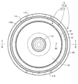
- FIG. 1 The whole perspective view which shows the electric rice cooker as one Embodiment of this invention.
- the top view of the electric rice cooker shown in FIG. The bottom view of the electric rice cooker shown in FIG.
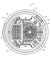
- the IV-IV cross section enlarged view in FIG.
- the electric rice cooker 10 includes a rice cooker 12 for containing rice, water and the like as a material to be cooked, and a rice cooker main body 16 having a pot housing recess 14 for containing the rice cooker 12 in a removable manner.
- the upper side means the upper side in FIGS. 1 and 4 and the lower side means the lower side in FIGS. 1 and 4 and the front means the left side and the rear side in FIGS. Shall mean the right side in FIGS.
- the cooking pot 12 has a pot body 18 made of pottery containing rice, water and the like as a food to be cooked, and a lid which covers the upper opening 20 which is the opening portion of the pot body 18. It is composed of a body 22. Both the pan body 18 and the lid 22 are made of porous pottery having a large number of micro-spaces open on the surface.
- the pot body 18 has a substantially cylindrical peripheral wall portion 24 and a substantially disc-like bottom portion 26 whose diameter increases toward the integrally formed upper opening 20, and has a substantially round pot shape as a whole. ing.
- the thickness dimension of the peripheral wall portion 24 is gradually thickened from the bottom portion 26 toward the upper opening 20, and the middle to upper ends of the circumferential wall portion 24 than the thickness dimension t 1 of the bottom portion 26 Thickness dimension: t2 is larger (t1 ⁇ t2).
- a flange portion 30 is provided at the upper end edge portion 28 of the pan body 18 of the rice cooker 12 so as to protrude in the substantially rectangular cross-sectional shape toward the outer peripheral side and spread over substantially the entire outer peripheral side.
- the bottom surface 32 of the flange portion 30 is provided with a downward slope which protrudes downward as it goes to the outer peripheral side. That is, such downward inclination is configured to approach the bottom wall 112 of the annular groove portion 110 as described later.
- the upper surface 34 of the flange portion 30 is also provided with a downward slope which protrudes downward as it goes to the outer peripheral side.
- step surfaces 36a and 36b having a substantially L-shaped cross-sectional shape are provided over substantially the entire periphery.
- the step surface 36 b is formed below and inward of the step surface 36 a.
- a temperature detection plate 38 is disposed at the central portion of the bottom portion 26 corresponding to the bottom surface of the pot body 18 of the rice cooker 12, and has a cross-sectional shape substantially similar to the temperature detection plate 38.
- the through hole 40 is formed. Since the outer shape of the temperature detection plate 38 and the through hole 40 have a T-like cross-sectional shape that is substantially similar, the temperature detection plate 38 can be stably held in the through hole 40. And while the temperature detection board 38 comprises a part of bottom part 26, while the sensor part 76a of the rice cooker main body 16 mentioned later abuts.
- the temperature detecting plate 38 is made of various metals, metal compounds, carbon, alumina, aluminum nitride or the like, which is a material having a heat transfer coefficient higher than that of the potter body 18 or the pottery constituting the lid 22.
- the temperature in the pan body 18 can be measured more accurately than in the case where the sensor portion 76a of the temperature sensor 76 is in pressure contact with the ceramic surface.
- the outer shape of the temperature detection plate 38 and the through hole 40 have a T-shaped cross-sectional shape that is substantially similar, the shape will be described in detail below taking the temperature detection plate 38 as an example.
- the temperature measuring plate 38 has a large diameter portion 42 on the inner surface side of the bottom portion 26 defining the inner peripheral surface of the pan body 18, and a small diameter portion on the outer surface side of the bottom portion 26 defining the outer peripheral surface of the pan body 18 44 and has a generally stepped cylindrical shape as a whole. Moreover, the step surface 46 between the large diameter portion 42 and the small diameter portion 44 of the temperature detection plate 38 is a downward inclined surface which descends toward the inner peripheral side.
- the above-described shape is a T-shaped cross-sectional shape in which the outer shape of the temperature detection plate 38 and the through hole 40 are similar.
- the temperature detection plate 38 is provided with a housing recess 48 which opens downward at the central portion of the outer surface and stores a sensor portion 76a described later.
- the inner surface 50 of the peripheral wall portion of the housing recess 48 has a tapered surface shape which spreads outward in the radial direction (left and right direction in FIG. 4) as it goes downward.
- the temperature detection plate 38 is formed into a stepped cylindrical shape, the temperature detection plate 38 can be reliably held at the stepped portion with respect to the through hole 40 of the similar shape provided in the bottom portion 26 of the pan body 18. It can be stably disposed at the bottom portion 26 of the pot body 18.
- the housing recess 48 for housing the sensor portion 76a is provided at the central portion of the outer surface, the sensor portion 76a can be stably positioned and held. Further, by providing the housing recess 48, the thickness of the portion where the sensor portion 76a abuts can be reduced, so that the temperature inside the pan body 18 can be detected more reliably.
- the step surface 46 between the large diameter portion 42 and the small diameter portion 44 of the temperature detection plate 38 is a downward inclined surface, the locking portion of the temperature detection plate 38 to the bottom portion 26 of the pan body 18 locally The stress concentration can be eliminated, and in the manufacturing process, the adhesive can be easily poured between the two, and the productivity can also be improved.
- the inner surface 50 of the peripheral wall portion of the housing recess 48 has a tapered surface shape that expands radially outward as it goes downward, the sensor portion 76 a is guided and housed in the housing recess 48. Thus, the temperature measuring plate 38 and the sensor section 76a can be positioned smoothly.
- the lid 22 of the rice cooker 12 is configured to include an inner lid 52 and an outer lid 54.
- the inner lid 52 has a substantially disc shape that spreads flat as a whole, and a columnar handle 56 that protrudes upward is integrally formed at a radial center portion.
- the thickness dimension t3 of the inner lid 52 is larger than the thickness dimension t1 of the bottom 26 and the thickness dimension t4 of the outer lid 54, and the thickness dimension from the middle to the upper end side of the peripheral wall 24: t2 It is smaller than the above (t1 ⁇ t4 ⁇ t3 ⁇ t2).
- a flange-like locking piece 58 extending toward the outer peripheral side over substantially the entire circumference is integrally formed.
- the inner lid 52 is formed with a pressure release hole (not shown) for pressing, which penetrates the inner lid 52 in the thickness direction.
- a plurality of protrusions 60 that project downward in a substantially dome shape are formed. As shown in FIG. 4, the inner lid 52 having such a structure holds the locking piece 58 of the inner lid 52 with the step surface 36 b of the upper end edge portion 28 of the pan main body 18 in a state in which the handle 56 is gripped.
- the upper opening 20 which is an opening of the pan body 18 can be covered by being engaged with the above.
- the outer lid 54 has a generally spherical shell shape as a whole, and a substantially cylindrical handle 62 protruding upward at the radial center portion. Is provided. Further, as shown in FIG. 2, a pressure release hole 64 is formed in the rear (rightward in FIG. 2) of the handle 62 with a substantially circular cross-sectional shape.
- the steam storage space 66 can be formed between the inner lid 52 and the inner lid 52 so as to be installed above the inner lid 52.
- the lid 22 has a double lid structure of the inner lid 52 and the outer lid 54 and the steam storage space 66 is formed between the inner lid 52 and the outer lid 54, it is possible to cook rice The pressure state and soaking inside the pan body 18 can be stably held.
- the inner lid 52 covers the upper opening 20 of the pot body 18 and spreads flatly and is thicker than the outer lid 54, the weight of the inner lid 52 causes the inside of the pot body 18 to be cooked at the time of cooking. The pressurization can be held more reliably, and good rice cooking can be realized.
- the rice cooker body 16 is provided with a pot housing recess 14, and the pot housing recess 14 is a bottom wall 68 and a bottom wall that are substantially circular in a plan view. It is configured to have a peripheral wall portion 70 which protrudes substantially upward in a substantially spherical shape from the outer peripheral edge portion 68 to substantially the entire periphery.
- the bottom wall 68 of the pot housing recess 14 is provided with a sheathed heater 72 as an electric heater for heating the rice cooker 12, and in a through hole 74 formed in the center of the sheathed heater 72.
- a temperature sensor 76 is provided.
- a blower fan 80 Inside the rice cooker body 16 on the bottom surface 78 side of the rice cooker body 16 located below the sheathed heater 72, there are provided a blower fan 80, and a control unit 82 for controlling the blower fan 80 and the sheathed heater 72. There is.
- the sheathed heater 72 has a structure in which a first sheathed heater 72a and a second sheathed heater 72b are held with respect to a sheathed heater holding member 84 having a substantially plate shape as a whole. have.
- the sheathed heater holding member 84 is made of metal, and the upper surface side thereof is substantially similar in shape to the bottom portion 26 of the pan body 18, while the lower surface side accommodates the first sheathed heater 72a and the second sheathed heater 72b.
- a sheathed heater receiving hole 86 for holding the lower end is formed to open downward and extend in a substantially spiral shape in the circumferential direction.
- the sheath heater 72 constituting the electric heater has the substantially disc-shaped first sheathed heater 72a on which the center of the bottom 26 of the pan body 18 is placed, and the periphery of the bottom 26 of the pan body 18 is placed
- the second sheathed heater 72b has a substantially annular shape.
- the sheathed heater 72 is fixed to a predetermined position in the rice cooker body 16 by fixing means (not shown). As a result, by controlling the output of the first sheathed heater 72a and the second sheathed heater 72b in accordance with the process of cooking, it is possible to advantageously adjust the temperature distribution of the pan body 18 at the time of cooking.
- a through hole 74 is provided at the central portion of the sheathed heater 72 that constitutes the bottom wall 68 of the pan housing recess 14, and a temperature sensor 76 is provided in the through hole 74.
- the sensor portion 76a is disposed so as to be extensible and contractible in the vertical direction in a state of being biased upward by an elastic member (not shown) such as a compression coil spring.
- an elastic member such as a compression coil spring.
- the temperature sensor 76 is connected to the temperature sensor support part 90 provided below the temperature sensor 76, the temperature sensor support part 90 is being fixed to the rice cooker main body 16 via the compression coil spring. Further, the temperature sensor 76 is disposed in a state of being protruded upward from the upper opening of the through hole 74. Thus, when the bottom portion 26 of the pan body 18 is placed on the sheathed heater 72, the sensor portion 76a of the temperature sensor 76 is the central portion of the bottom portion 26 of the pan body 18 based on the biasing force of the compression coil spring. The bottom surface of the housing recess 48 of the temperature measuring plate 38 disposed in the housing is in pressure contact.
- the rear side of the rice cooker body 16 located on the bottom surface 78 side, which is located below the sheathed heater 72 that constitutes the bottom wall 68 of the pan housing recess 14 (see FIG. Among the four, the blower fan 80 is provided on the right side), while the control unit 82 made of a circuit board is provided on the front side (the left side in FIG. 4).
- a suction port 92a consisting of a number of substantially strip-like through holes extending substantially in a radial shape over substantially the entire surface.
- the air intakes 92a and 92b allow the outside air to be efficiently introduced into the rice cooker body 16. More specifically, the outside air introduced into the rice cooker body 16 from the air inlet 92a is sent upward to cool the sheathed heater 72 that constitutes the bottom wall portion 68 of the pot housing recess 14, and to be described later The air is exhausted upward through the air passage 102 defined between the recess 14 and the pot body 18.
- the outside air introduced into the rice cooker main body 16 from the air inlet 92b is sent upward to cool the control unit 82 and the sheathed heater 72, and to draw the space between the pot housing recess 14 and the pot body 18 described later.
- the air is exhausted upward through the formed air passage 102.
- a cover 93 made of a substantially rectangular box-shaped synthetic resin is opened above the control unit 82 toward the control unit 82 to prevent the water or the like from being applied to the control unit 82 or the sheathed heater 72.
- leg portions 94 projecting in a substantially solid truncated cone shape are provided at four places separated in the circumferential direction (see FIGS. 3 and 4).
- the peripheral wall portion 70 of the pot housing recess 14 is outwardly with respect to the outer peripheral edge portion 96 of the sheath heater 72 that constitutes the bottom wall portion 68 of the pot housing recess 14. It is formed to project upward in a substantially cylindrical shape whose diameter gradually increases upward from a position spaced apart toward the upper side.
- rubber protrusions 98 projecting inward of the pan housing recess 14 are provided at four places separated at equal intervals in the circumferential direction.
- the rubber projection 98 is brought into pressure contact with the outer peripheral surface of the peripheral wall portion 24 of the pot body 18 in a state where the cooking pot 12 is accommodated in the pot accommodation recess 14, the peripheral wall portion 70 of the pot accommodation recess 14 and the pot
- the pan body 18 is housed in the pan housing recess 14 in a state where a gap of a predetermined size is formed between the pan 18 and the outer peripheral surface of the peripheral wall portion 24 of the main body 18.
- the air gap 102 which spreads in the circumferential direction and the up-and-down direction is formed between the peripheral wall portion 70 of the pot housing recess 14 and the outer peripheral surface of the peripheral wall portion 24 of the pot body 18 by this gap.
- the peripheral wall part 70 is made into the lower peripheral wall part 70b below.
- the upper peripheral wall 70a and the lower peripheral wall 70b constituting the peripheral wall 70 are both made of metal and are separately molded.
- the upper end opening 104 of the air passage 102 is outside at the upper opening 106 of the pan accommodation recess 14.
- the lower end opening 108 of the air flow passage 102 is in communication with the inside of the rice cooker body 16 while being in direct communication with the More specifically, the air blowing passage 102 has an annular shape that spreads over the entire circumference between the peripheral wall portion 70 of the pot housing recess 14 and the outer peripheral surface of the peripheral wall portion 24 of the pot body 18.
- the upper end opening 104 of the air passage 102 is constituted by an upper annular clearance ⁇ formed between the upper end edge of the peripheral wall 70 of the pot housing recess 14 and the upper end edge 28 of the pot body 18.
- the lower annular clearance provided at the lower end opening 108 of the air flow path 102 between the peripheral wall 70 of the pot housing recess 14 and the sheath heater 72 constituting the bottom wall 68 of the pot housing recess 14 It is configured.
- the gap dimension ⁇ between the upper peripheral wall 70 a of the pan housing recess 14 and the peripheral wall 24 of the pan body 18 in the air flow path 102 is expanded toward the upper end opening 104.
- annular recessed groove 110 is opened upward and extends over substantially the entire outer periphery of the upper peripheral wall 70a.
- the outer peripheral side of the upper peripheral wall 70a is provided continuously.
- the annular groove portion 110 is substantially wedge-shaped, and includes a bottom wall 112, an inner circumferential side wall 114a projecting upward from an end edge portion on the inner circumferential side of the bottom wall 112, and an outer circumferential side of the bottom wall 112. And an outer peripheral side wall 114b protruding upward from the end edge.
- the tip of the inner circumferential side wall 114a of the annular groove 110 is connected to the tip of the upper circumferential wall 70a, and the bottom wall 112 is formed below the tip of the upper circumferential wall 70a.
- the tip end portion of the outer peripheral side wall 114b of the annular recessed groove portion 110 protrudes upward beyond the tip end portion of the upper peripheral wall portion 70a, and the cooking pot 12 is accommodated in the pot accommodation recess 14 It is formed so as to be located slightly below the outer peripheral edge of the upper surface 34 of the flange portion 30.
- the outer peripheral end face of the flange portion 30 provided on the upper end edge portion 28 of the pot body 18 is an annular shape of the rice cooker main body 16 provided therebelow It is positioned immediately above the recessed groove portion 110.
- the bottom surface 32 of the flange portion 30 is inclined downward toward the outer peripheral side, it is possible to prevent the blowout etc.
- the outer periphery of the annular groove 110 The tip end of the side wall 114b is formed to be located below the tip end of the upper peripheral wall 70a.
- an operation panel 118 provided with, for example, a liquid crystal display and various touch panel type operation switches is installed. Inside the operation panel 118, a control unit 120 for the operation panel 118 is disposed. In addition, a substantially rectangular box-like synthetic resin cover 122 opening toward the control unit 120 is disposed behind the control unit 120 (rightward in FIG. 4), and water, etc. for the control unit 120 is provided. It is possible to advantageously realize the prevention of the hooking and the shutoff of the heat from the sheathed heater 72.
- the electric rice cooker 10 of the structure according to such this embodiment is used in the state which the rice cooker 12 was accommodated in the pot accommodation recess 14, as FIG. 4 shows. In this state, substantially the entire upper end edge 28 of the pot body 18 and the lid 22 are exposed to the outside at the upper opening 106 of the pot housing recess 14.
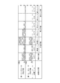
- the process of rice cooking is comprised including a water absorption process, a temperature rising process, a cooking process, and a steaming process, as FIG. 5 shows.
- a water absorption process is performed.
- rice, water and the like as rice to be cooked (not shown) are contained in the pot body 18 of the rice cooker 12 in a state of being accommodated in the pot accommodation recess 14 of the rice cooker body 16. It is done in the state of containing. Since the pot body 18 is made of pottery having low thermal conductivity, the temperature does not easily rise and temperature unevenness easily occurs. Therefore, in the present embodiment, in the water absorption process before the temperature raising process, a preheating operation is performed in which heating is performed in advance. As shown in FIG.
- this preheating operation is carried out by heating the control unit 82 with an output value of, for example, approximately 50% for approximately 20 minutes using both sheathed heaters 72a and 72b in the water absorption process. Ru.
- the time taken for the water absorption process is utilized to heat the pan body 18, and the pot body 18 made of ceramic takes a long time to realize the desired temperature in the pan body 18 from the beginning of the heating process. be able to.
- the control unit 82 causes the blower fan 80 to be in the OFF (non-operation) state.
- a temperature raising step is performed.
- the control unit 82 subsequently executes the heating of the pan body 18 using both sheathed heaters 72a and 72b.
- the output value of the sheathed heater 72a, 72b in the temperature raising step is, for example, 20%, 10% for 5 minutes in the temperature raising (i) (see FIG. 5) at the beginning of the temperature raising step. It is lower than 50% of the output value of 72b.
- the temperature in the pan body 18 is made optimum for cooking by eliminating temperature unevenness using the heat storage property of the pottery. Can.
- the output values of the sheathed heaters 72a and 72b are heated at 90% and 50% for 10 minutes, for example. It is possible to raise the temperature to the optimum temperature. Also in the temperature raising process, the blower fan 80 is in the OFF (non-operation) state by the control unit 82.
- a cooking process is performed after a temperature rising process.
- the control unit 82 is performed by heating the pan body 18 using only the first sheathed heater 72 a.
- the output value in the cooking process of the first sheathed heater 72a is, for example, 40% at 5 minutes in cooking (i) (see FIG. 5) at the beginning of the cooking process, while the output value in the second half of the cooking process In cooking (ii), for example, it is 5 minutes at 20%.
- the cooking process can be performed using only the first sheathed heater 72a on which the center of the bottom portion 26 of the pot body 18 is placed by utilizing the heat storage property of the pot body 18 made of pottery. Therefore, power-saving rice cooking using the heat storage property of the pot body 18 made of pottery is possible.
- the control unit 82 causes the blower fan 80 to be in the OFF (non-operation) state.
- the steaming process is performed after the cooking process.
- the control unit 82 sets the output value of both sheathed heaters 72a and 72b to, for example, 0%. It is about 15 minutes and the blower fan 80 is driven.
- the outside air introduced from the lower end opening 108 of the air flow path 102 can be continuously discharged from the upper end opening 104 without staying in the air flow path 102, so that the entire pan body 18 is cooled. It can be promoted.
- the second half of the steaming process (ii) see FIG.
- the control unit 82 sets only the output value of the first sheathed heater 72a to, eg, 10% for about 5 minutes and turns off the blower fan 80 (not Operation) state.
- the control unit 82 continuously drives the blower fan 80 to continuously pass the outside air to the blower path 102, and at the beginning of the steaming process in which the sheathed heaters 72a and 72b are turned off (i Period (15 minutes) covers over 70% of the total period (15 minutes + 5 minutes) of the steaming process.
- the control unit 82 turns off the sheathed heaters 72a and 72b for a period of 70% or more of the steaming process from the steaming (i) at the beginning of the steaming process and continuously introduces external air into the air passage 102 Can continue to be done. Therefore, heat dissipation of the pot body 18 can be promptly performed to maintain the temperature of the pot body 18 suitable for the steaming process, and it is possible to cook plump delicious rice. Further, as shown in FIG.
- the pot body 18 of the rice cooker 12 is directly connected by the sheath heater 72 provided on the bottom wall portion 68 of the pot housing recess 14 of the rice cooker body 16. It is supposed to be heated. Therefore, as with the traditional pot door, the temperature rise of the pot body 18 gradually due to direct heating of the pot body 18 made of pottery, the soaking at the time of temperature rise, and the heat storage property after heating You can cook rice deliciously by making good use of it. Moreover, since the sheathed heater 72 is used, the control unit 82 can also maintain the convenience of the electric rice cooker 10 such as reserved rice cooking as it is.
- an air passage 102 extending in the circumferential direction and in the vertical direction is formed between the peripheral wall portion 70 of the pot housing recess 14 and the outer peripheral surface of the peripheral wall portion 24 of the pot body 18.
- the lower end opening 108 of the air passage 102 is in communication with the inside of the rice cooker body 16 while the air channel 104 is in direct communication with the outside.
- external air introduced from the lower end opening 108 of the air passage 102 is retained in the air passage 102 only by driving the air blower fan 80 in the steaming process where the heat storage property of the pot body 18 made of ceramics becomes a problem. Since the liquid can be discharged continuously from the upper end opening 104, the entire cooling of the pot body 18 can be promoted.
- the controller 82 has a drying mode.
- the drying step is performed in a state where only the pan body 18 containing rice, water, and the like as the food to be cooked is accommodated in the pan accommodating recess 14 of the rice cooker body 16. More specifically, the drying process is performed so as to promote the drying of the pan body 18 by the control unit 82 driving the sheathed heater 72 and the blower fan 80 that constitute the electric heater. Since the drying of the pot body 18 after use which tends to be carried out can be reliably performed by this drying process, the initial state of the pot body 18 can be maintained, and maintenance and improvement of the durability of the pot body 18 can be achieved. it can.
- the lid 22 of the cooking pot 12 is also made of the same pottery as the pot body 18, but the cover 22 does not necessarily have to be made of pottery. It is possible to use any material such as one made by Meanwhile, earthenware pot body, in order to maintain high heat storage, bulk density or measured by JIS A 1509 is, 1.5g / cm 3 ⁇ 2.3g / cm 3, preferably 2.0 g / cm 3 is a ⁇ 2.1g / cm 3, in the present embodiment has a 2.05g / cm 3 ⁇ 2.08g / cm 3.
- the JIS of the pot body made of pottery The water absorption measured by A 1509 is 6 to 12%, preferably 8 to 10%, and is 9% in this embodiment.
- the sheathed heater 72 is used as the electric heater. However, the sheathed heater 72 is not limited to the sheathed heater, and a known electric heater such as a ceramic heater or a carbon heater can be adopted.
- the output value of the first sheathed heater 72a is, for example, about 5 minutes at 10% and the blower fan 80 is in the OFF (non-operational) state
- the latter half of the steaming process is steamed
- a step of turning off both sheathed heaters 72a and 72b without driving the blower fan 80 in (ii) may be incorporated to discharge excess water.
- the continuous driving of the blower fan 80 and the OFF state of both sheathed heaters 72a and 72b may be maintained throughout the steaming process.
- the embodiment of the present invention includes an embodiment in which rice is cooked by performing forced cooling by the blower fan 80 in the steaming step.
- the second sheathed heater 72b is turned off in the cooking process, and only the first sheathed heater 72a is used.
- the first sheathed heater 72a and the second sheathed heater 72a are used according to cooking preference. It can be modified to use at least one of the heaters 72b. That is, in the cooking process, the first sheathed heater 72a may be turned off and only the second sheathed heater 72b may be used, or both the first and second sheathed heaters 72a and 72b may be used. .
Landscapes
- Engineering & Computer Science (AREA)
- Food Science & Technology (AREA)
- Cookers (AREA)
- Thermally Insulated Containers For Foods (AREA)
- Glass Compositions (AREA)
Abstract
複雑な制御を必要とすることなく、簡単な構造でより美味しい御飯を炊き上げることができる、新規な構造の電気炊飯器を提供すること。 炊飯鍋12が、陶器製の鍋本体18と蓋体22から構成されていると共に、鍋収容凹所14の上方開口部106において蓋体22が外部に露呈されている一方、鍋収容凹所14の周壁部70と炊飯鍋12の鍋本体18との間に周方向および上下方向に広がる送風路102が形成されていると共に、送風路102の上端開口部104が、鍋収容凹所14の上方開口部106において外部に直接連通されている一方、送風路102の下端開口部108が炊飯器本体16内に連通されており、制御部82が、炊飯の蒸らし工程において送風ファン80を駆動して、送風路102の下端開口部108から導入された外気を、送風路102内に滞留させることなく上端開口部104から連続的に排出させるようにした。
Description
本発明は、陶器製の炊飯鍋を用いた電気炊飯器に関する。
従来から、加熱時間等の管理が容易で簡便に炊飯が可能な機器として、電気炊飯器が広く用いられている。近年では、加熱効率が高く早く美味しい御飯を炊き上げることができる、特許第4910441号公報(特許文献1)に記載の如き電磁誘導加熱式の電気炊飯器も普及している。
ところで、陶器製の土鍋を用いて炊き上げた御飯は、熱源により直接加熱されていることから、加熱された陶器からの輻射熱の効果により、お米の芯まで均一に加熱され一粒一粒がふっくらと立ち上がった美味しい御飯が炊けることで知られている。このため、特許公報1に記載のとおり、電磁誘導加熱式の電気炊飯器であってもセラミック製の内鍋を採用し、内鍋の底部および底部近傍に誘電効率の高い金属製のペーストを塗布することで、電磁誘導加熱により金属製ペーストを誘導発熱し、内鍋を間接的に加熱する構造も提案されている。
ところが、セラミック等の非金属製の内鍋を採用すると、磁性金属製の内鍋の場合に比して熱伝導性が劣り熱斑が生じ易く、被炊飯物の均一な加熱が実現され難い。そこで、送風ファンからの風で電磁誘導加熱手段を冷却することで得た熱風を、内鍋側部の周囲に設けた間隔が狭い熱風溜まり空間内に滞留させることにより、内鍋の低温部分を加温して内鍋の均熱化を図る構造が提案されている。
しかしながら、熱風溜まりによる内鍋の加温程度では、十分かつ速やかな内鍋の均熱化を図ることができず、結果的に需要者の満足が得られる炊飯を行うには不十分であった。しかも、送風ファンを内鍋を加熱する目的で利用する必要があることから、炊き上げ工程の所定のタイミングで送風を行ったり、蒸らし工程では断続的に送風ファンを駆動するなど、送風ファンの駆動制御が複雑となり易い問題を内在していた。
本発明は、上述の事情を背景に為されたものであって、複雑な制御を必要とすることなく、簡単な構造でより美味しい御飯を炊き上げることができる、新規な構造の電気炊飯器を提供することにある。
以下、このような課題を解決するために為された本発明の態様を記載する。なお、以下に記載の各態様において採用される構成要素は、可能な限り任意の組み合わせで採用可能である。
本発明の第一の態様は、被炊飯物を収容する炊飯鍋と、該炊飯鍋を取り出し可能に収容する鍋収容凹所を有する炊飯器本体と、該鍋収容凹所の底壁部に設けられて前記炊飯鍋を加熱する電気ヒータと、該炊飯器本体内に設けられた送風ファンと、該電気ヒータと該送風ファンを制御する制御部と、を備えた電気炊飯器において、前記炊飯鍋が、前記被炊飯物を収容する陶器製の鍋本体と該鍋本体の開口部を覆蓋する蓋体から構成されていると共に、前記炊飯器本体の前記鍋収容凹所に前記炊飯鍋が収容された状態で、該鍋収容凹所の上方開口部において前記蓋体が外部に露呈されている一方、該鍋収容凹所の周壁部と該炊飯鍋の該鍋本体との間に周方向および上下方向に広がる送風路が形成されていると共に、前記送風路の上端開口部が、前記鍋収容凹所の前記上方開口部において外部に直接連通されている一方、前記送風路の下端開口部が前記炊飯器本体内に連通されており、前記制御部が、炊飯の蒸らし工程において前記送風ファンを駆動して、前記送風路の前記下端開口部から導入された外気を、前記送風路内に滞留させることなく前記上端開口部から連続的に排出させるようになっていることを特徴とする。
本発明によれば、炊飯器本体の鍋収容凹所の底壁部に電気ヒータを設置すると共に、かかる鍋収容凹所に陶器製の鍋本体を収容して、鍋本体を電気ヒータで直接加熱する構造が採用されている。これにより、昔ながらの釜戸と同様に、陶器製の鍋本体が直接加熱される場合の鍋本体の緩やかな温度上昇性や温度上昇時における均熱化、さらに加熱後の蓄熱性の高さを巧く利用することにより、お米を美味しく炊き上げることができるのである。しかも、熱源は電気ヒータを利用していることから、制御部によって電気ヒータのオン・オフを制御することができ、予約炊飯など電気炊飯器の利便性もそのまま保持することができる。
さらに、炊飯鍋の陶器製鍋本体の開口部を覆蓋する蓋体が、炊飯器本体の鍋収容凹所に炊飯鍋が収容された状態で、鍋収容凹所の上方開口部において外部に露呈されている。これにより、蓄熱性の高い材料で構成された炊飯鍋の上方への放熱性が安定して確保され、陶器製鍋本体の蓄熱性の高さに起因する不必要なお米の焦げ付きなどを有利かつ簡便に防止することができる。
加えて、鍋収容凹所の周壁部と炊飯鍋の鍋本体との間に形成される周方向および上下方向に広がる送風路は、その上端開口部が、鍋収容凹所の上方開口部において外部に直接連通されている。このような構造の送風路に対して、制御部が、炊飯の蒸らし工程において、送風ファンを駆動して送風路の下端開口部から導入された外気を、送風路内に滞留させることなく上端開口部から連続的に排出させるようになっている。したがって、陶器製の鍋本体の蓄熱性が問題となる蒸らし工程において、送風ファンを駆動するだけで、送風路に外気を連続して通過させることができ、鍋本体の全体の冷却を促進することが可能となっている。特に、送風路の上端開口部が外部に直接連通していることから、送風路からの速やかな空気の排出が実現でき、空気の滞留を防止して鍋本体の速やかな冷却に寄与することができる。
なお、炊飯鍋において、蓋体は必ずしも陶器製である必要はなく、陶器製の他、鋳物製やガラス製など任意の材料を用いることができる。また、陶器製の鍋本体は、高い蓄熱性を保持するために、JIS A 1509により測定したかさ密度が、1.5g/cm3 ~2.3g/cm3 、好ましくは2.0g/cm3 ~2.1g/cm3 とされている。加えて、陶器製の鍋本体のJIS A 1509により測定した吸水率が、6~12%、好ましくは8~10%とされている。
本発明の第二の態様は、前記第一の態様に記載のものにおいて、前記制御部が、前記蒸らし工程の冒頭から該蒸らし工程の全期間の7割以上の期間に亘って、連続して前記送風ファンを駆動して該送風路に外気を連続して通過させると共に、前記電気ヒータをオフにしているものである。
本態様によれば、陶器製の鍋本体の蓄熱性が問題となる蒸らし工程において、冒頭から全期間の7割以上の期間に亘って、電気ヒータがオフにされると共に連続して送風路に外気が導入され続け、鍋本体の放熱を速やかに実行することができ、蒸らし工程に適した鍋本体の温度を維持することができ、ふっくらとした美味しい御飯を炊き上げることができる。なお、本態様の送風ファンの連続駆動と電気ヒータのオフの状態は、蒸らし工程の冒頭から7割以上の期間で実施されていればよく、炊飯の内容によっては、蒸らし工程の最後に送風ファンを駆動せず電気ヒータをオフにして余分な水分を飛ばす工程を組み入れたり、蒸らし工程の全期間において送風ファンの連続駆動と電気ヒータのオフの状態を維持するようにしてもよい。
本発明の第三の態様は、前記第一または第二の態様に記載のものにおいて、前記制御部が、前記蒸らし工程以外の工程において、前記送風ファンを駆動しないようになっているものである。
本態様によれば、蒸らし工程以外の工程において、送風ファンが駆動しないようになっていることから、送風路を通過する外気による陶器製の鍋本体の放熱が防止されており、陶器製の鍋本体の蓄熱性を利用した炊飯を有利に実現することができる。
本発明の第四の態様は、前記第一乃至第三の何れか1つの態様に記載のものにおいて、前記送風路が、前記鍋収容凹所の前記周壁部と前記鍋本体との間の全周に亘って広がる環形状を呈しており、前記送風路の前記上端開口部が、前記周壁部の上端縁部と該鍋本体の上端縁部の間に形成された上側環状隙間によって構成されている一方、前記送風路の前記下端開口部が前記周壁部と前記底壁部の間に設けられた下側環状隙間によって構成されているものである。
本態様によれば、送風路が、鍋収容凹所の周壁部と鍋本体との間の全周に亘って広がる環形状を呈し、かつ送風路の上端開口部と下端開口部が共に、全周に亘って開口する環形状を呈している。これにより、送風路を通過する外気の挿通が妨げられることがなく、一層速やかな外気の挿通とそれによる鍋本体の冷却を実現することができる。
本発明の第五の態様は、前記第一乃至第四の何れか1つの態様に記載のものにおいて、前記送風路における前記周壁部と前記鍋本体の間の隙間寸法が、前記上端開口部に向かって拡大しているものである。
本態様によれば、送風路の隙間寸法が上端開口部に向かって拡大していることから、送風路内への外気の滞留を一層確実に回避して、より速やかな外気の挿通およびそれによる鍋本体の冷却が可能となる。
本発明の第六の態様は、前記第一乃至第五の何れか1つの態様に記載のものにおいて、前記炊飯器本体の前記上方開口部側には、上方に開口する環状凹溝部が前記周壁部の外周側に連接して設けられており、該環状凹溝部の底壁が前記周壁部の先端部よりも下方に位置するように設けられている一方、前記炊飯鍋の前記鍋本体の上端縁部には、外周側に広がるフランジ部が設けられ、該フランジ部の外周端面が前記環状凹溝部の直上に位置するように設けられており、該フランジ部の底面には、外周側に向かうにしたがって前記環状凹溝部の前記底壁に接近する下方傾斜がつけられているものである。
本態様によれば、鍋本体の上端縁部に設けられたフランジ部の外周端面が、その下方に設けられた炊飯器本体の環状凹溝部の直上に位置するようになっている。これにより、炊飯時の吹きこぼれなどが、フランジ部を伝って外部に漏れた場合でも、環状凹溝部に収容することができ、使用後の清掃等を簡便に行うことが可能となる。しかも、フランジ部の底面には、外周側に向かうにしたがって環状凹溝部の底壁に接近する下方傾斜がつけられていることから、フランジ部の底面を伝って吹きこぼれが鍋収容凹所側に入り込むことが未然に防止されている。
本発明の第七の態様は、前記第一乃至第六の何れか1つの態様に記載のものにおいて、前記炊飯鍋の前記蓋体が、前記鍋本体の開口部を覆蓋して平坦に広がる内蓋と、該内蓋の上方に設置されて該内蓋との間に蒸気収納空間を形成する外蓋とを含んでおり、該内蓋に肉厚寸法が該外蓋の肉厚寸法よりも大きくされているものである。
本態様によれば、炊飯鍋の蓋体が、内蓋と外蓋の二重部蓋構造とされており、内蓋と外蓋の間に蒸気収納空間が形成されていることから、炊飯時の鍋本体内部の加圧状態や均熱化を安定して保持することができる。さらに、内蓋が、鍋本体の開口部を覆蓋して平坦に広がると共に、外蓋よりも厚肉に形成されていることから、内蓋の重量によって炊飯時の鍋本体内部の加圧を一層確実に保持することができ、良好な炊飯を実現することができる。
本発明の第八の態様は、前記第一乃至第七の何れか1つの態様に記載のものにおいて、前記電気ヒータが、前記鍋本体の底部中央が載置される第一シーズヒータと、前記鍋本体の底部周縁が載置される第二シーズヒータを含んで構成されているものである。
本態様によれば、第一シーズヒータと第二シーズヒータを、炊飯の工程に合わせてそれぞれのオン/オフや出力制御をすることが可能となる。これにより、炊飯時の鍋本体の温度分布をより有利に調整することができる。
本発明の第九の態様は、前記第八の態様に記載のものにおいて、前記制御部が、炊飯の昇温工程において、前記第一シーズヒータと前記第二シーズヒータの両方を使用する一方、その後の炊上工程では、前記第一シーズヒータと前記第二シーズヒータの少なくとも一方を使用するようになっているものである。
本態様によれば、陶器製の鍋本体の蓄熱性を利用して、炊上工程では、鍋本体の底部中央が載置される第一シーズヒータと第二シーズヒータの少なくとも一方の使用とすることができる。これにより、陶器製の鍋本体の蓄熱性を利用した省電力な炊飯が可能となる。
本発明の第十の態様は、前記第九の態様に記載のものにおいて、前記炊上工程では、前記第一シーズヒータのみを使用するようになっているものである。
本発明の第十の態様は、前記第九の態様に記載のものにおいて、前記炊上工程では、前記第一シーズヒータのみを使用するようになっているものである。
本発明の第十一の態様は、前記第八乃至第十の何れか1つの態様に記載のものにおいて、前記第一および第二シーズヒータの前記昇温工程における出力値が、前記昇温工程の冒頭において、吸水工程の出力値よりも下げられているものである。
本態様によれば、加温に時間を要する陶器製の鍋本体を吸水工程の時間を巧く利用して加温を行い、昇温工程の冒頭から所望の鍋本体内の温度を実現することができる。さらに、一旦昇温工程の冒頭でヒータの出力を落とすことにより、鍋本体内の温度を炊飯に最適な状態に保つことができる。
本発明の第十二の態様は、前記第一乃至第十一の何れか1つの態様に記載のものにおいて、前記制御部が、被炊飯物を収容しない前記鍋本体が前記鍋収容凹所に収容された状態で、前記電気ヒータと前記送風ファンを駆動させて前記鍋本体の乾燥を促進する乾燥モードを含んでいるものである。
本態様によれば、使用後の陶器製の鍋本体を鍋収容凹所に収容した状態で鍋本体の乾燥工程を行うことできる。これにより、わすれがちな使用後の鍋本体の乾燥を使用者に確実に実行させることができ、鍋本体の製品状態の維持や耐久性の向上を図ることができる。
本発明の第十三の態様は、前記第一乃至第十二の何れか1つの態様に記載のものにおいて、前記鍋収容凹所の底壁部中央には、温度センサのセンサ部が配設されている一方、前記鍋本体の底面には、該底面の一部を構成すると共に前記センサ部が当接される検温板が配設されており、前記検温板が、前記陶器よりも熱伝達率の高い素材で構成されているものである。
本態様によれば、温度センサのセンサ部が圧接される検温部が、陶器よりも熱伝達率の高い素材で構成されていることから、検温板の内表面が接する鍋本体内の温度が、温度センサのセンサ部に速やかに伝達され、陶器表面に圧接されたセンサ部により検知する場合に比して、鍋本体内の温度をより正確に検温することができる。なお、温度センサのセンサ部が弾性部材によって上方に付勢された状態で配設することにより、炊飯鍋の有無を検知する機構を有利に兼ね備えることができる。また、検温板の素材としては、陶器よりも熱伝達率の高い素材であれば何れでもよいが、好ましくは、アルミニウムやアルミニウム合金等の金属製や、カーボン製のものを採用することができる。
本発明の第十四の態様は、前記第十三の態様に記載のものにおいて、前記検温板が、前記鍋本体の内周面を画成する内表面側に比して、前記鍋本体の外周面を画成する外表面側の径寸法が小さい段付き円柱形状とされており、前記検温板の前記外表面の中央部には前記センサ部を収容する収容凹所が設けられているものである。
本態様によれば、検温板が段付き円柱形状とされていることから、鍋本体の底面に対して段差部分で確実に保持されることができ、検温板を安定して鍋本体の底面に配設することができる。しかも、外表面の中央部には、収容凹所が設けられていることから、センサ部を安定して位置決め保持することができる。また、収容凹所を設けることで検温板部のセンサ部が当接される部位の板厚を薄くすることができ、一層確実かつ速やかに鍋本体の内部の温度を検知することができる。
本発明の第十五の態様は、前記第十四の態様に記載のものにおいて、前記検温板の大径部と小径部の間の段差面が、内周側に行くに従って下降する下方傾斜面とされている一方、前記収容凹所の周壁部が下方に行くにしたがって径方向外方に広がるテーパ面形状を有しているものである。
本態様によれば、小径部と大径部の間の段差面が下方傾斜面とされていることから、検温板の鍋本体の底壁部への係止部分において局所的な応力の集中を解消することができる。さらに、収容凹所が下方に向かって径方向外方に広がるテーパ面形状とされていることから、センサ部をセンタリングしつつ収容することができ、検温板とセンサ部の位置決めを一層スムーズに行うことができる。
本発明によれば、炊飯器本体の鍋収容凹所の底壁部に電気ヒータを設置すると共に、鍋本体を電気ヒータで直接加熱する構造が採用されている。これにより、陶器製の鍋本体が直接加熱される場合の鍋本体の緩やかな温度上昇性や温度上昇時における均熱化、さらに加熱後の蓄熱性の高さを巧く利用することにより、お米を美味しく炊き上げることができる。しかも、熱源は電気ヒータを利用していることから、予約炊飯など電気炊飯器の利便性もそのまま保持できる。さらに、蓋体が、鍋収容凹所の上方開口部において外部に露呈されている。これにより、蓄熱性の高い材料で構成された炊飯鍋の上方への放熱性が安定して確保され、陶器製鍋本体の蓄熱性の高さに起因する不必要なお米の焦げ付きなどを有利かつ簡便に防止できる。加えて、送風路は、その上端開口部が、鍋収容凹所の上方開口部において外部に直接連通されている。このような構造の送風路に対して、制御部が、炊飯の蒸らし工程において、送風ファンを駆動して送風路の下端開口部から導入された外気を、送風路内に滞留させることなく上端開口部から連続的に排出させるようになっている。したがって、陶器製の鍋本体の蓄熱性が問題となる蒸らし工程において、送風ファンを駆動するだけで、送風路に外気を連続して通過させることができ、鍋本体の全体の冷却を促進できる。
以下、本発明の実施形態について、図面を参照しつつ説明する。
図1~4には、本発明の一実施形態としての電気炊飯器10が示されている。電気炊飯器10は、被炊飯物としての飯米や水等を収容する炊飯鍋12と、炊飯鍋12を取り出し可能に収容する鍋収容凹所14を有する炊飯器本体16と、を備えて構成されている。なお、以下の説明において、上方とは、図1,4中の上方、下方とは、図1,4中の下方を言い、また前方とは、図1~2,4中の左方、後方とは、図1~2,4中の右方を言うものとする。
図4に示されているように、炊飯鍋12は、被炊飯物としての飯米や水等を収容する陶器製の鍋本体18と、鍋本体18の開口部たる上方開口部20を覆蓋する蓋体22から構成されている。鍋本体18と蓋体22は、いずれも表面に開口する多数の微小空間を有する多孔質の陶器製とされている。鍋本体18は、一体的に形成された上方開口部20に向かって拡径する略円筒形状の周壁部24と略円板状の底部26を有しており、全体として略丸釜形状を呈している。本実施形態では、周壁部24の肉厚寸法は、底部26から上方開口部20に向かって次第に厚肉にされており、底部26の肉厚寸法:t1よりも周壁部24の中間から上端の肉厚寸法:t2の方が大きくされている(t1<t2)。また、炊飯鍋12の鍋本体18の上端縁部28には、外周側に向かって略矩形断面形状で突出して外周側の略全周に亘って広がるようにフランジ部30が設けられている。かかるフランジ部30の底面32には、外周側に向かうにしたがって下方に向かって突出する下方傾斜がつけられている。すなわち、かかる下方傾斜は、後述するように、環状凹溝部110の底壁112に接近するように構成されている。さらに、フランジ部30の上面34にも、外周側に向かうにしたがって下方に向かって突出する下方傾斜がつけられている。加えて、鍋本体18の上端縁部28の内周側には、略全周に亘って略L字断面形状の段差面36a,36bが設けられている。ここで、段差面36bは、段差面36aよりも下方かつ内方に形成されている。
また、図4に示されているように、炊飯鍋12の鍋本体18の底面にあたる底部26の中央部には、検温板38が配設される、検温板38と略相似の断面形状を有する貫通孔40が形成されている。検温板38の外形と貫通孔40が略相似のT字断面形状を有していることから、検温板38が貫通孔40内に安定して保持可能となっている。そして、検温板38は、底部26の一部を構成すると共に後述する炊飯器本体16のセンサ部76aが当接されるようになっている。かかる検温板38は、鍋本体18や蓋体22を構成する陶器よりも熱伝達率の高い素材である、各種金属や金属化合物あるいはカーボンやアルミナや窒化アルミニウム等によって構成されている。これにより、温度センサ76のセンサ部76aが陶器表面に圧接された場合に比して、鍋本体18内の温度をより正確に検温できる。ここで、検温板38の外形と貫通孔40が略相似のT字断面形状を有していることから、以下では検温板38を例にとってその形状について詳述することにする。検温板38は、鍋本体18の内周面を画成する底部26の内表面側が大径部42とされている一方、鍋本体18の外周面を画成する底部26の外表面側が小径部44とされており、全体として略段付き円柱形状を呈している。しかも、検温板38の大径部42と小径部44の間の段差面46が、内周側に行くに従って下降する下方傾斜面とされている。以上の形状が、検温板38の外形と貫通孔40の相似するT字断面形状である。なお、検温板38には貫通孔40とは異なり、外表面の中央部において下方に向かって開口して後述するセンサ部76aを収容する収容凹所48が設けられている。ここで、かかる収容凹所48の周壁部の内面50が下方に行くにしたがって径方向(図4中、左右方向)外方に広がるテーパ面形状を有している。
上述のように検温板38が段付き円柱形状とされていることから、鍋本体18の底部26に設けられた相似形状の貫通孔40に対して段差部分で確実に保持でき、検温板38を安定して鍋本体18の底部26に配設することができる。しかも、外表面の中央部にセンサ部76aを収容する収容凹所48が設けられていることから、センサ部76aを安定して位置決め保持できる。また、収容凹所48を設けることによってセンサ部76aが当接される部位の板厚を薄くすることができることから、より確実に鍋本体18の内部の温度を検知できる。加えて、検温板38の大径部42と小径部44の間の段差面46が下方傾斜面とされていることから、検温板38の鍋本体18の底部26への係止部分において局所的な応力の集中を解消でき、製造工程においては、両者の間に接着剤を流し込み易くなり、製造性の向上も図ることができる。さらに、収容凹所48の周壁部の内面50が下方に行くにしたがって径方向外方に広がるテーパ面形状を有していることから、センサ部76aをガイドして収容凹所48に収容することができ、検温板38とセンサ部76aの位置決めをスムーズに行うことができるようになっている。
一方、図4に示されているように、炊飯鍋12の蓋体22は、内蓋52と外蓋54とを含んで構成されている。本実施形態では、いずれも鍋本体18と同様、陶器製とされている。内蓋52は、全体として平坦に広がる略円板形状を有しており、径方向中央部分には上方に向かって突出する柱状の取っ手56が一体形成されている。また、内蓋52の肉厚寸法:t3は、底部26の肉厚寸法:t1や外蓋54の肉厚寸法:t4よりも大きくされ、周壁部24の中間から上端側の肉厚寸法:t2よりも小さくされている(t1≒t4<t3<t2)。さらに、内蓋52の外周縁部の上端部分には、略全周に亘って外周側に向かって延び出すフランジ状の係止片58が一体形成されている。加えて、内蓋52には、図示しない圧抜き用の圧抜き孔が、内蓋52を肉厚方向で貫通して形成されている。また、内蓋52の下面には、下方に向かって略ドーム形状で突出する突部60が複数形成されている。このような構造とされた内蓋52は、図4に示されているように、取っ手56を把持した状態で内蓋52の係止片58を鍋本体18の上端縁部28の段差面36bに係合させることにより、鍋本体18の開口部たる上方開口部20を覆蓋できるようになっている。一方、外蓋54は、図1,4に示されているように、全体として略球殻形状を有しており、径方向中央部分には、上方に向かって突出する略筒状の取っ手62が設けられている。また、図2に示されているように、取っ手62の後方(図2中、右方)には、略円形断面形状で貫設された圧抜き孔64が形成されている。このような構造とされた外蓋54が、図4に示されているように、取っ手62を把持した状態で外蓋54の外周縁部を鍋本体18の上端縁部28の段差面36aに係合させることにより、内蓋52の上方に設置されて内蓋52との間に蒸気収納空間66が形成できるようになっている。このように、蓋体22が内蓋52と外蓋54の二重部蓋構造とされていると共に内蓋52と外蓋54の間に蒸気収納空間66が形成されていることから、炊飯時における鍋本体18内部の加圧状態や均熱化を安定して保持できるのである。さらに、内蓋52が鍋本体18の上方開口部20を覆蓋して平坦に広がると共に外蓋54よりも厚肉とされていることから、内蓋52の重量によって炊飯時における鍋本体18内部の加圧をより確実に保持することができ、良好な炊飯を実現できるようになっている。
図4に示されているように、炊飯器本体16は鍋収容凹所14を備えている一方、かかる鍋収容凹所14は平面視で略円形状とされた底壁部68と底壁部68の外周縁部から略全周に亘って略球殻形状で上方に向かって突出する周壁部70を有して構成されている。鍋収容凹所14の底壁部68には、炊飯鍋12を加熱する電気ヒータとしてのシーズヒータ72が設けられていると共に、シーズヒータ72の中央部に貫設された貫通孔74内には温度センサ76が配設されている。さらに、シーズヒータ72の下方に位置する炊飯器本体16の底面78側の炊飯器本体16内には、送風ファン80と、送風ファン80とシーズヒータ72を制御する制御部82と、を備えている。
シーズヒータ72は、図4に示されているように、全体として略皿形状を有しているシーズヒータ保持部材84に対して、第一シーズヒータ72aと第二シーズヒータ72bが保持された構造を有している。かかるシーズヒータ保持部材84は金属製とされており、上面側が鍋本体18の底部26と略相似形状とされている一方、下面側には第一シーズヒータ72aと第二シーズヒータ72bを収容して保持するためのシーズヒータ収容穴86が、下方に向かって開口すると共に周方向に略渦巻き状に延び出して形成されている。より詳細には、第一シーズヒータ72aが略皿形状とされたシーズヒータ保持部材84の略円板形状の底壁84aに保持されている一方、第二シーズヒータ72bは略皿形状とされたシーズヒータ保持部材84の略円環形状の底壁周縁84bに保持されている。このように、電気ヒータを構成するシーズヒータ72は、鍋本体18の底部26の中央が載置される略円板形状の第一シーズヒータ72aと、鍋本体18の底部26の周縁が載置される略円環形状の第二シーズヒータ72bを含んで構成されているのである。なお、かかるシーズヒータ72は、炊飯器本体16内の所定位置に対して図示しない固定手段によって固定されている。この結果、第一シーズヒータ72aと第二シーズヒータ72bを炊飯の工程に合わせて出力制御をすることにより、炊飯時における鍋本体18の温度分布を有利に調整することが可能となっている。
図4に示されているように、鍋収容凹所14の底壁部68を構成するシーズヒータ72の中央部には貫通孔74が設けられており、かかる貫通孔74内には温度センサ76のセンサ部76aが、圧縮コイルスプリング等の弾性部材(図示せず)によって上方に付勢された状態で上下方向に伸縮自在に配設されている。これにより、炊飯鍋12の有無を検知する機構も有利に兼ね備えることができるようになっている。温度センサ76は、先端面がセンサ部76aとされており、このセンサ部76aにおいて被検出物に当接することで被検出物の温度を検出する公知の構造を有している。また、温度センサ76が、温度センサ76の下方に設けられた温度センサ支持部90に連結されている一方、温度センサ支持部90は圧縮コイルスプリングを介して炊飯器本体16に固定されている。さらに、温度センサ76が、貫通孔74の上方開口部から上方に突出された状態で配置されている。これにより、鍋本体18の底部26がシーズヒータ72上に載置されたときに、温度センサ76のセンサ部76aが、圧縮コイルスプリングの付勢力に基づいて、鍋本体18の底部26の中央部に配設されている検温板38の収容凹所48の底面に対して圧接されるようになっている。
また、図4に示されているように、鍋収容凹所14の底壁部68を構成するシーズヒータ72の下方に位置する、底面78側の炊飯器本体16内には、後方側(図4中、右方側)に送風ファン80が設けられている一方、前方側(図4中、左方側)には回路基板からなる制御部82が設けられている。かかる送風ファン80が設けられた炊飯器本体16の底面78には略全面に亘って略放射線状に延びる多数の略短冊状の貫通孔からなる吸気口92aが形成されている一方、制御部82が設けられた炊飯器本体16の底面78には略全面に亘って略前後方向(図3中、左右方向)に延びる多数の略短冊状の貫通孔からなる吸気口92bが形成されている(図3,4参照)。かかる吸気口92a,92bにより、炊飯器本体16内に効率的に外気を取り入れることができるようになっている。より詳細には、吸気口92aから炊飯器本体16内に取り入れられた外気は上方に送られて鍋収容凹所14の底壁部68を構成するシーズヒータ72を空冷すると共に、後述する鍋収容凹所14と鍋本体18との間に画成される送風路102を通って上方に向かって排気されるようになっている。また、吸気口92bから炊飯器本体16内に取り入れられた外気は上方に送られて制御部82とシーズヒータ72を空冷すると共に、後述する鍋収容凹所14と鍋本体18との間に画成される送風路102を通って上方に向かって排気される。さらに、制御部82の上方には制御部82に向かって開口する略矩形箱体状の合成樹脂製のカバー93が配設されており、制御部82に対する水等の掛かりの防止やシーズヒータ72からの熱の遮断を有利に実現できるようになっている。また、炊飯器本体16の底面78には、周方向に離隔する4ケ所において略中実円錐台形状で突出する脚部94が設けられている(図3,4参照)。
一方、図4に示されているように、鍋収容凹所14の周壁部70は、鍋収容凹所14の底壁部68を構成するシーズヒータ72の外周縁部96に対して外方に向かって離隔した位置から、上方に向かって次第に拡径する略円筒形状で上方に向かって突出して形成されている。かかる周壁部70の上下方向の略中央部には、周方向に等間隔で離隔した4箇所に鍋収容凹所14の内方に向かって突出するゴム突部98が設けられている。そして、ゴム突部98が、炊飯鍋12が鍋収容凹所14に収容された状態で鍋本体18の周壁部24の外周面に圧接することにより、鍋収容凹所14の周壁部70と鍋本体18の周壁部24の外周面との間に所定の寸法の隙間を形成した状態で鍋本体18が鍋収容凹所14に収容されるようになっている。かかる隙間によって、鍋収容凹所14の周壁部70と鍋本体18の周壁部24の外周面との間に周方向および上下方向に広がる送風路102が形成されている。そして、周壁部70は、ゴム突部98を境として、上方側が上方周壁部70aとされている一方、下方側が下方周壁部70bとされている。かかる周壁部70を構成する上方周壁部70aと下方周壁部70bはいずれも金属製とされており、それぞれ別体成形されている。
また、図4に示されているように、炊飯鍋12が鍋収容凹所14に収容された状態において、送風路102の上端開口部104が、鍋収容凹所14の上方開口部106において外部に直接連通されている一方、送風路102の下端開口部108が炊飯器本体16内に連通されている。より詳細には、送風路102は、鍋収容凹所14の周壁部70と鍋本体18の周壁部24の外周面との間の全周に亘って広がる環形状を呈しているのである。そして、送風路102の上端開口部104が、鍋収容凹所14の周壁部70の上端縁部と鍋本体18の上端縁部28の間に形成された上側環状隙間:αによって構成されている一方、送風路102の下端開口部108が鍋収容凹所14の周壁部70と鍋収容凹所14の底壁部68を構成するシーズヒータ72の間に設けられた下側環状隙間:βによって構成されているのである。これにより、送風路102を通過する外気の挿通が妨げられることがなく、より速やかな外気の挿通とそれによる鍋本体18の冷却を実現することができる。さらに、送風路102における鍋収容凹所14の上方周壁部70aと鍋本体18の周壁部24の間の隙間寸法:γが、上端開口部104に向かって拡大している。この結果、送風路102内への外気の滞留をより確実に回避して速やかな外気の挿通を実現できることから、鍋本体18の速やかな冷却が可能となっている。
加えて、炊飯器本体16の鍋収容凹所14の上方開口部106側には、上方に向かって開口すると共に上方周壁部70aの外周の略全周に亘って延出する環状凹溝部110が、上方周壁部70aの外周側に連接して設けられている。かかる環状凹溝部110は略樋形状とされており、底壁112と、底壁112の内周側の端縁部から上方に向かって突出する内周側壁114aと、底壁112の外周側の端縁部から上方に向かって突出する外周側壁114bと、有している。そして、環状凹溝部110の内周側壁114aの先端部が上方周壁部70aの先端部と連接されて、底壁112が上方周壁部70aの先端部よりも下方に位置するように形成されている。一方、環状凹溝部110の外周側壁114bの先端部は、上方周壁部70aの先端部を越えて上方に向かって突出し、炊飯鍋12が鍋収容凹所14に収容された状態で鍋本体18のフランジ部30の上面34の外周縁部よりもわずかに下方に位置するように形成されている。また、炊飯鍋12が鍋収容凹所14に収容された状態で、鍋本体18の上端縁部28に設けられたフランジ部30の外周端面が、その下方に設けられた炊飯器本体16の環状凹溝部110の直上に位置するようになっている。これにより、炊飯時に吹きこぼれ等がフランジ部30の上面34を伝って外部に漏れた場合でも環状凹溝部110に収容できることから、使用後の清掃等を簡便に行うことができるようになっている。しかも、フランジ部30の底面32には外周側に向かって下方傾斜がつけられていることから、フランジ部30の底面32を伝って吹きこぼれ等が鍋収容凹所14側に入り込むことが未然に防止されている。また、フランジ部30の上面34にも外周側に向かって下方傾斜がつけられていることから、炊飯時の吹きこぼれ等がフランジ部30の上面34を伝って確実に環状凹溝部110に収容できるようになっている。さらに、炊飯鍋12を炊飯器本体16の鍋収容凹所14に設置する際に鍋本体18のフランジ部30を手指で把持する場合に、フランジ部30の底面32の下方傾斜により手指のフランジ部30への係合性が向上され、安定した取扱性を実現できる。なお、炊飯器本体16の周壁部100の対向する上端部が略矩形状に切り欠かれて形成された切欠部116においては(図1参照)、図示は省略するが、環状凹溝部110の外周側壁114bの先端部が、上方周壁部70aの先端部よりも下方に位置するように形成されている。これにより、両手の手指を切欠部116に挿入することで、炊飯鍋12を鍋収容凹所14に収容する際に手指を炊飯鍋12と炊飯器本体16との間に挟むおそれを有利に低減乃至はなくすることができる。
加えて、炊飯器本体16の周壁部100における前方側(図4中、左側)の外面には、例えば液晶ディスプレイや各種のタッチパネル式の操作スイッチを備えた操作パネル118が設置されている。かかる操作パネル118の内方には、操作パネル118用の制御部120が配設されている。また、制御部120の後方(図4中、右方)には制御部120に向かって開口する略矩形箱体状の合成樹脂製のカバー122が配設されており、制御部120に対する水等の掛かりの防止やシーズヒータ72からの熱の遮断を有利に実現できるようになっている。
このような本実施形態に従う構造の電気炊飯器10は、図4に示されているように、炊飯鍋12が鍋収容凹所14に収容された状態で使用される。なお、かかる状態においては、鍋収容凹所14の上方開口部106において鍋本体18の上端縁部28および蓋体22の略全体が外部に露呈されている。
炊飯の工程は、図5に示されているように、吸水工程と、昇温工程と、炊上工程と、蒸らし工程と、を含んで構成されている。最初に、吸水工程が実行される。かかる吸水工程は、図4に示すように、炊飯器本体16の鍋収容凹所14に収容された状態の炊飯鍋12の鍋本体18内に、図示しない被炊飯物としての飯米や水等を収容した状態で行われる。鍋本体18が熱伝導性が低い陶器製とされていることから、温度が上がりにくくまた温度ムラが生じやすい。それゆえ、本実施形態では、昇温工程前の吸水工程において、予め加熱する予熱作業が行われている。かかる予熱作業は、図5に示されているように、吸水工程において、制御部82が両方のシーズヒータ72a,72bを用いて例えば50%程度の出力値で20分程度加熱することによって実行される。これにより、吸水工程の時間を巧く利用して鍋本体18の加熱を行い、加熱に時間を要する陶器製の鍋本体18を昇温工程の冒頭から所望の鍋本体18内の温度を実現することができる。なお、かかる予熱作業中の吸水工程においては、制御部82によって送風ファン80がOFF(非動作)状態とされている。
かかる吸水工程後には、昇温工程が実行される。かかる昇温工程では、図5に示されているように、引き続き制御部82が両方のシーズヒータ72a,72bを用いて鍋本体18を加熱することによって実行される。かかるシーズヒータ72a,72bの昇温工程における出力値は、昇温工程の冒頭の昇温(i)(図5参照)において例えば20%,10%で5分となり、吸水工程におけるシーズヒータ72a,72bの出力値の50%よりも下げられている。このように一旦昇温工程の冒頭でシーズヒータ72a,72bの出力を落とすことにより、陶器の蓄熱性を利用して鍋本体18内の温度を温度ムラをなくして炊飯に最適な状態にすることができる。さらに、昇温工程の昇温(ii)(図5参照)において、シーズヒータ72a,72bの出力値を例えば90%,50%で10分加熱することにより、鍋本体18内の温度を炊飯に最適な温度まで昇温することができるようになっている。なお、かかる昇温工程においても、制御部82によって送風ファン80がOFF(非動作)状態とされている。
次に、昇温工程後には、炊上工程が実行される。かかる炊上工程では、図5に示されているように、制御部82が第一シーズヒータ72aのみを用いて鍋本体18を加熱することによって実行される。かかる第一シーズヒータ72aの炊上工程における出力値は、炊上工程の冒頭の炊上(i)(図5参照)において例えば40%で5分とされている一方、炊上工程の後半の炊上(ii)においては例えば20%で5分とされている。このように炊上工程では、陶器製の鍋本体18の蓄熱性を利用することにより、鍋本体18の底部26中央が載置される第一シーズヒータ72aのみを用いて行うことができる。それゆえ、陶器製の鍋本体18の蓄熱性を利用した省電力な炊飯が可能となっている。なお、かかる炊上工程においても、制御部82によって送風ファン80がOFF(非動作)状態とされている。
最後に、炊上工程後には、蒸らし工程が実行される。かかる蒸らし工程では、図5に示されているように、蒸らし工程の冒頭の蒸らし(i)(図5参照)において、制御部82が両方のシーズヒータ72a,72bの出力値を例えば0%で15分程度とすると共に送風ファン80を駆動させている。これにより、送風路102の下端開口部108から導入された外気を、送風路102内に滞留させることなく上端開口部104から連続的に排出させることができることから、鍋本体18の全体の冷却を促進できるようになっている。また、蒸らし工程の後半の蒸らし(ii)(図5参照)においては、制御部82が第一シーズヒータ72aの出力値のみを例えば10%で5分程度とすると共に送風ファン80をOFF(非動作)状態としている。以上により、炊飯の工程全体が終了し、以降は保温工程となる。このように、制御部82が、連続して送風ファン80を駆動して送風路102に外気を連続して通過させると共に、シーズヒータ72a,72bをオフにしている蒸らし工程の冒頭の蒸らし(i)の期間(15分)が、蒸らし工程の全期間(15分+5分)の7割以上の期間に亘っている。これにより、制御部82が、蒸らし工程の冒頭の蒸らし(i)から蒸らし工程の7割以上の期間に亘ってシーズヒータ72a,72bがオフにされると共に連続して送風路102に外気が導入され続けることができる。それゆえ、鍋本体18の放熱を速やかに実行して蒸らし工程に適した鍋本体18の温度を維持することができ、ふっくらとした美味しい御飯を炊き上げることができる。また、図5に示されているように、蒸らし工程以外の工程において、制御部82が送風ファン80を駆動しないようになっていることから、送風路102を通過する外気による陶器製の鍋本体18の放熱が防止されており、陶器製の鍋本体18の蓄熱性を利用した炊飯を有利に実現することができるようになっている。
このような本発明に従う構成とされた電気炊飯器10によれば、炊飯器本体16の鍋収容凹所14の底壁部68に設けられたシーズヒータ72により炊飯鍋12の鍋本体18を直接加熱するようになっている。それゆえ、昔ながらの釜戸と同様に、陶器製の鍋本体18が直接加熱されることによる鍋本体18の緩やかな温度上昇性や温度上昇時における均熱化および加熱後の蓄熱性の高さを巧く利用することにより、お米を美味しく炊き上げることができる。しかも、シーズヒータ72を利用していることから、制御部82によって予約炊飯など電気炊飯器10の利便性もそのまま保持することができる。
さらに、炊飯鍋12が鍋収容凹所14に収容された状態で、鍋収容凹所14の上方開口部106において鍋本体18の上端縁部28および蓋体22の略全体が外部に露呈されている。これにより、蓄熱性の高い材料で構成された炊飯鍋12の上方への放熱性が安定して確保されると共に、かかる蓄熱性の高さに起因する不必要なお米の焦げ付きなどを有利かつ簡便に防止できる。
加えて、鍋収容凹所14の周壁部70と鍋本体18の周壁部24の外周面との間に周方向および上下方向に広がる送風路102が形成されており、送風路102の上端開口部104が外部に直接連通されている一方、送風路102の下端開口部108が炊飯器本体16内に連通されている。これにより、陶器製の鍋本体18の蓄熱性が問題となる蒸らし工程において送風ファン80を駆動するだけで、送風路102の下端開口部108から導入された外気を、送風路102内に滞留させることなく上端開口部104から連続的に排出させることができることから、鍋本体18の全体の冷却を促進できる。
なお、本実施形態では、制御部82は乾燥モードを有している。かかる乾燥工程は、被炊飯物としての飯米や水等が収容されていない鍋本体18のみを炊飯器本体16の鍋収容凹所14に収容した状態で行われる。より詳細には、乾燥工程は、制御部82が電気ヒータを構成するシーズヒータ72と送風ファン80を駆動させることにより、鍋本体18の乾燥を促進するように行われる。かかる乾燥工程により、わすれがちな使用後の鍋本体18の乾燥を確実に行うことができることから、鍋本体18の初期状態を維持して、鍋本体18の耐久性の維持・向上を図ることができる。
以上、本発明の一実施形態について説明してきたが、これはあくまでも例示であって、本発明は、かかる実施形態における具体的な記載によって、何等、限定的に解釈されるものではない。
例えば、上記実施形態では、炊飯鍋12の蓋体22も鍋本体18と同じく陶器製とされていたが、蓋体22は必ずしも陶器製である必要はなく、陶器製の他、鋳物製やガラス製など任意の材料を用いることができる。一方、陶器製の鍋本体は、高い蓄熱性を保持するために、JIS A 1509により測定したかさ密度が、1.5g/cm3 ~2.3g/cm3 、好ましくは2.0g/cm3 ~2.1g/cm3 とされ、本実施形態では2.05g/cm3 ~2.08g/cm3 となっている。加えて、陶器製の鍋本体のJIS
A 1509により測定した吸水率が、6~12%、好ましくは8~10%とされ、本実施形態では9%となっている。また、上記実施形態では、電気ヒータはシーズヒータ72とされていたが、これに限定されず、セラミックヒータやカーボンヒータ等の公知の電気ヒータが採用可能である。
A 1509により測定した吸水率が、6~12%、好ましくは8~10%とされ、本実施形態では9%となっている。また、上記実施形態では、電気ヒータはシーズヒータ72とされていたが、これに限定されず、セラミックヒータやカーボンヒータ等の公知の電気ヒータが採用可能である。
さらに、上記実施形態では、蒸らし工程の後半の蒸らし(ii)では、第一シーズヒータ72aの出力値のみを例えば10%で5分程度とすると共に送風ファン80をOFF(非動作)状態としていたが、これに限定されない。すなわち、連続して送風ファン80を駆動すると共に両方のシーズヒータ72a,72bの出力値がゼロとされている期間を蒸らし工程の全期間の7割以上とした状態で、蒸らし工程の後半の蒸らし(ii)で送風ファン80を駆動せず両方のシーズヒータ72a,72bをオフにして余分な水分を飛ばす工程を組み入れてもよい。もしくは、蒸らし工程の全期間において本実施形態の蒸らし(i)のように送風ファン80の連続駆動と両方のシーズヒータ72a,72bのオフの状態を維持するようにしてもよい。
上記実施形態では、電気ヒータを第一シーズヒータ72aと第二シーズヒータ72bで構成した例を示したが、単一の電気ヒータを用い、陶器製の鍋本体18の蓄熱性のみを利用しかつ蒸らし工程で送風ファン80による強制冷却を行うことにより、炊飯を行う態様も本発明に含まれることは言うまでもない。
上記実施形態では、炊上工程において第二シーズヒータ72bをOFFにして、第一シーズヒータ72aのみを使用する例を示したが、炊き上がりの好みに応じて第一シーズヒータ72aと第二シーズヒータ72bの少なくとも一方を使用するように変更可能である。すなわち、炊上工程において、第一シーズヒータ72aをOFFにして第二シーズヒータ72bのみを使用してもよいし、第一,第二シーズヒータ72a,72bの両方を使用するようにしてもよい。
その他、一々列挙はしないが、本発明は、当業者の知識に基づいて種々なる変更,修正,改良等を加えた態様において実施され得るものであり、また、そのような実施態様が、本発明の趣旨を逸脱しない限り、何れも、本発明の範囲内に含まれるものであることは、言うまでもない。
10:電気炊飯器、12:炊飯鍋、14:鍋収容凹所、16:炊飯器本体、18:鍋本体、20:上方開口部(開口部)、22:蓋体、26:底部(底面)、28:上端縁部、30:フランジ部、32:底面、38:検温板、42:大径部、44:小径部、46:段差面、48:収容凹所、50:内面、52:内蓋、66:蒸気収納空間、68:底壁部、70:周壁部、72:シーズヒータ(電気ヒータ)、72a:第一シーズヒータ、72b:第二シーズヒータ、76:温度センサ、76a:センサ部、80:送風ファン、82:制御部、102:送風路、104:上端開口部、106:上方開口部、108:下端開口部、110:環状凹溝部、112:底壁
Claims (15)
- 被炊飯物を収容する炊飯鍋と、該炊飯鍋を取り出し可能に収容する鍋収容凹所を有する炊飯器本体と、該鍋収容凹所の底壁部に設けられて前記炊飯鍋を加熱する電気ヒータと、該炊飯器本体内に設けられた送風ファンと、該電気ヒータと該送風ファンを制御する制御部と、を備えた電気炊飯器において、
前記炊飯鍋が、前記被炊飯物を収容する陶器製の鍋本体と該鍋本体の開口部を蓋覆する蓋体から構成されていると共に、
前記炊飯器本体の前記鍋収容凹所に前記炊飯鍋が収容された状態で、該鍋収容凹所の上方開口部において前記蓋体が外部に露呈されている一方、該鍋収容凹所の周壁部と該炊飯鍋の該鍋本体との間に周方向および上下方向に広がる送風路が形成されていると共に、
前記送風路の上端開口部が、前記鍋収容凹所の前記上方開口部において外部に直接連通されている一方、前記送風路の下端開口部が前記炊飯器本体内に連通されており、
前記制御部が、炊飯の蒸らし工程において前記送風ファンを駆動して、前記送風路の前記下端開口部から導入された外気を、前記送風路内に滞留させることなく前記上端開口部から連続的に排出させるようになっている
ことを特徴とする電気炊飯器。 - 前記制御部が、前記蒸らし工程の冒頭から該蒸らし工程の全期間の7割以上の期間に亘って、連続して前記送風ファンを駆動して該送風路に外気を連続して通過させると共に、前記電気ヒータをオフにしている請求項1に記載の電気炊飯器。
- 前記制御部が、前記蒸らし工程以外の工程において、前記送風ファンを駆動しないようになっている請求項1または2に記載の電気炊飯器。
- 前記送風路が、前記鍋収容凹所の前記周壁部と前記鍋本体との間の全周に亘って広がる環形状を呈しており、前記送風路の前記上端開口部が、前記周壁部の上端縁部と該鍋本体の上端縁部の間に形成された上側環状隙間によって構成されている一方、前記送風路の前記下端開口部が前記周壁部と前記底壁部の間に設けられた下側環状隙間によって構成されている請求項1~3の何れか1項に記載の電気炊飯器。
- 前記送風路における前記周壁部と前記鍋本体の間の隙間寸法が、前記上端開口部に向かって拡大している請求項1~4の何れか1項に記載の電気炊飯器。
- 前記炊飯器本体の前記上方開口部側には、上方に開口する環状凹溝部が前記周壁部の外周側に連接して設けられており、該環状凹溝部の底壁が前記周壁部の先端部よりも下方に位置するように設けられている一方、
前記炊飯鍋の前記鍋本体の上端縁部には、外周側に広がるフランジ部が設けられ、該フランジ部の外周端面が前記環状凹溝部の直上に位置するように設けられており、該フランジ部の底面には、外周側に向かうにしたがって前記環状凹溝部の前記底壁に接近する下方傾斜がつけられている請求項1~5の何れか1項に記載の電気炊飯器。 - 前記炊飯鍋の前記蓋体が、前記鍋本体の開口部を蓋覆して平坦に広がる内蓋と、該内蓋の上方に設置されて該内蓋との間に蒸気収納空間を形成する外蓋とを含んでおり、該内蓋に肉厚寸法が該外蓋の肉厚寸法よりも大きくされている請求項1~6の何れか1項に記載の電気炊飯器。
- 前記電気ヒータが、前記鍋本体の底部中央が載置される第一シーズヒータと、前記鍋本体の底部周縁が載置される第二シーズヒータを含んで構成されている請求項1~7の何れか1項に記載の電気炊飯器。
- 前記制御部が、炊飯の昇温工程において、前記第一シーズヒータと前記第二シーズヒータの両方を使用する一方、その後の炊上工程では、前記第一シーズヒータと前記第二シーズヒータの少なくとも一方を使用するようになっている請求項8に記載の電気炊飯器。
- 前記炊上工程では、前記第一シーズヒータのみを使用するようになっている請求項9に記載の電気炊飯器。
- 前記第一および第二シーズヒータの前記該昇温工程における出力値が、前記昇温工程の冒頭において、吸水工程の出力値よりも下げられている請求項8~10の何れか1項に記載の電気炊飯器。
- 前記制御部が、被炊飯物を収容しない前記鍋本体が前記鍋収容凹所に収容された状態で、前記電気ヒータと前記送風ファンを駆動させて前記鍋本体の乾燥を促進する乾燥モードを含んでいる請求項1~11の何れか1項に記載の電気炊飯器。
- 前記鍋収容凹所の底壁部中央には、温度センサのセンサ部が配設されている一方、
前記鍋本体の底面には、該底面の一部を構成すると共に前記センサ部が当接される検温板が配設されており、
前記検温板が、前記陶器よりも熱伝達率の高い素材で構成されている請求項1~12に記載の電気炊飯器。 - 前記検温板が、前記鍋本体の内周面を画成する内表面側に比して、前記鍋本体の外周面を画成する外表面側の径寸法が小さい段付き円柱形状とされており、
前記検温板の前記外表面の中央部には前記センサ部を収容する収容凹所が設けられている請求項13に記載の電気炊飯器。 - 前記検温板の大径部と小径部の間の段差面が、内周側に行くに従って下降する下方傾斜面とされている一方、前記収容凹所の周壁部が下方に行くにしたがって径方向外方に広がるテーパ面形状を有している請求項14に記載の電気炊飯器。
Priority Applications (2)
| Application Number | Priority Date | Filing Date | Title |
|---|---|---|---|
| KR1020207012526A KR102351771B1 (ko) | 2017-10-27 | 2018-10-26 | 전기 밥솥 |
| CN201880070233.5A CN111278334A (zh) | 2017-10-27 | 2018-10-26 | 电饭锅 |
Applications Claiming Priority (2)
| Application Number | Priority Date | Filing Date | Title |
|---|---|---|---|
| JP2017-208160 | 2017-10-27 | ||
| JP2017208160A JP6553151B2 (ja) | 2017-10-27 | 2017-10-27 | 電気炊飯器 |
Publications (1)
| Publication Number | Publication Date |
|---|---|
| WO2019083005A1 true WO2019083005A1 (ja) | 2019-05-02 |
Family
ID=66247919
Family Applications (1)
| Application Number | Title | Priority Date | Filing Date |
|---|---|---|---|
| PCT/JP2018/039831 WO2019083005A1 (ja) | 2017-10-27 | 2018-10-26 | 電気炊飯器 |
Country Status (5)
| Country | Link |
|---|---|
| JP (1) | JP6553151B2 (ja) |
| KR (1) | KR102351771B1 (ja) |
| CN (1) | CN111278334A (ja) |
| TW (1) | TWI772541B (ja) |
| WO (1) | WO2019083005A1 (ja) |
Cited By (1)
| Publication number | Priority date | Publication date | Assignee | Title |
|---|---|---|---|---|
| EP4154773A1 (en) * | 2021-09-24 | 2023-03-29 | Norqi ApS | Electrically heated cooking device |
Families Citing this family (2)
| Publication number | Priority date | Publication date | Assignee | Title |
|---|---|---|---|---|
| JP7227490B2 (ja) * | 2019-05-27 | 2023-02-22 | タイガー魔法瓶株式会社 | 炊飯器 |
| JP7161244B1 (ja) * | 2021-06-18 | 2022-10-26 | シロカ株式会社 | 加熱調理器 |
Citations (8)
| Publication number | Priority date | Publication date | Assignee | Title |
|---|---|---|---|---|
| JPH02274207A (ja) * | 1989-04-17 | 1990-11-08 | Hitachi Home Tec Ltd | 加熱調理器 |
| JPH03261415A (ja) * | 1990-03-12 | 1991-11-21 | Matsushita Electric Ind Co Ltd | 炊飯器 |
| JPH09248242A (ja) * | 1996-03-15 | 1997-09-22 | Tiger Vacuum Bottle Co Ltd | 電気炊飯器 |
| JPH10262817A (ja) * | 1997-03-22 | 1998-10-06 | Paloma Ind Ltd | ガス炊飯器 |
| JP2007044306A (ja) * | 2005-08-10 | 2007-02-22 | Mitsubishi Electric Corp | 加熱調理器およびその鍋状容器の乾燥方法 |
| JP2007252624A (ja) * | 2006-03-23 | 2007-10-04 | Tiger Vacuum Bottle Co Ltd | 電気炊飯器 |
| JP2009273743A (ja) * | 2008-05-16 | 2009-11-26 | Rinnai Corp | 調理鍋 |
| JP2009293806A (ja) * | 2008-06-02 | 2009-12-17 | Nagatani Seito Kk | 加熱調理器とそれを構成するカバー部材 |
Family Cites Families (3)
| Publication number | Priority date | Publication date | Assignee | Title |
|---|---|---|---|---|
| JPS4910441B1 (ja) | 1968-01-05 | 1974-03-11 | ||
| KR101632742B1 (ko) * | 2014-05-28 | 2016-06-22 | 정원식 | 인덕션 조리기 |
| CN204698350U (zh) * | 2015-05-13 | 2015-10-14 | 黄俊杰 | 双层锅盖的陶瓷锅 |
-
2017
- 2017-10-27 JP JP2017208160A patent/JP6553151B2/ja active Active
-
2018
- 2018-10-19 TW TW107136939A patent/TWI772541B/zh active
- 2018-10-26 CN CN201880070233.5A patent/CN111278334A/zh active Pending
- 2018-10-26 KR KR1020207012526A patent/KR102351771B1/ko active IP Right Grant
- 2018-10-26 WO PCT/JP2018/039831 patent/WO2019083005A1/ja active Application Filing
Patent Citations (8)
| Publication number | Priority date | Publication date | Assignee | Title |
|---|---|---|---|---|
| JPH02274207A (ja) * | 1989-04-17 | 1990-11-08 | Hitachi Home Tec Ltd | 加熱調理器 |
| JPH03261415A (ja) * | 1990-03-12 | 1991-11-21 | Matsushita Electric Ind Co Ltd | 炊飯器 |
| JPH09248242A (ja) * | 1996-03-15 | 1997-09-22 | Tiger Vacuum Bottle Co Ltd | 電気炊飯器 |
| JPH10262817A (ja) * | 1997-03-22 | 1998-10-06 | Paloma Ind Ltd | ガス炊飯器 |
| JP2007044306A (ja) * | 2005-08-10 | 2007-02-22 | Mitsubishi Electric Corp | 加熱調理器およびその鍋状容器の乾燥方法 |
| JP2007252624A (ja) * | 2006-03-23 | 2007-10-04 | Tiger Vacuum Bottle Co Ltd | 電気炊飯器 |
| JP2009273743A (ja) * | 2008-05-16 | 2009-11-26 | Rinnai Corp | 調理鍋 |
| JP2009293806A (ja) * | 2008-06-02 | 2009-12-17 | Nagatani Seito Kk | 加熱調理器とそれを構成するカバー部材 |
Cited By (1)
| Publication number | Priority date | Publication date | Assignee | Title |
|---|---|---|---|---|
| EP4154773A1 (en) * | 2021-09-24 | 2023-03-29 | Norqi ApS | Electrically heated cooking device |
Also Published As
| Publication number | Publication date |
|---|---|
| KR20200066658A (ko) | 2020-06-10 |
| CN111278334A (zh) | 2020-06-12 |
| JP2019076661A (ja) | 2019-05-23 |
| TW201922154A (zh) | 2019-06-16 |
| KR102351771B1 (ko) | 2022-01-18 |
| TWI772541B (zh) | 2022-08-01 |
| JP6553151B2 (ja) | 2019-07-31 |
Similar Documents
| Publication | Publication Date | Title |
|---|---|---|
| WO2019083005A1 (ja) | 電気炊飯器 | |
| JP5025154B2 (ja) | 電気炊飯器 | |
| JP4416714B2 (ja) | 圧力加熱調理器 | |
| JP2005282893A (ja) | 加熱調理器 | |
| JP2019076661A5 (ja) | ||
| TWM538765U (zh) | 電子鍋 | |
| JP5316524B2 (ja) | 電気炊飯器 | |
| JP2794684B2 (ja) | 電気釜 | |
| KR101754358B1 (ko) | 휴대용 전기 조리기기 | |
| JP6197167B2 (ja) | 電気炊飯器 | |
| JP2004065536A (ja) | 加熱調理器 | |
| JP6161585B2 (ja) | 電気炊飯器 | |
| JP2012040428A (ja) | 電気炊飯器 | |
| CN220695047U (zh) | 烹饪器具 | |
| CN213605920U (zh) | 一种电烤炉 | |
| JP5527459B2 (ja) | 電気炊飯器 | |
| JP2004065766A (ja) | 調理容器および調理器 | |
| JP2003299569A (ja) | 炊飯器 | |
| JP2005174705A (ja) | 加熱調理器 | |
| JP2003325323A (ja) | 調理容器および調理器 | |
| JP2009072254A (ja) | 炊飯器 | |
| CN112568689A (zh) | 烹饪器具和烹饪器具的控制方法 | |
| JP6299440B2 (ja) | ホットプレート | |
| JPH05103719A (ja) | 炊飯器 | |
| JP2009219737A (ja) | 炊飯器 |
Legal Events
| Date | Code | Title | Description |
|---|---|---|---|
| 121 | Ep: the epo has been informed by wipo that ep was designated in this application |
Ref document number: 18870517 Country of ref document: EP Kind code of ref document: A1 |
|
| NENP | Non-entry into the national phase |
Ref country code: DE |
|
| ENP | Entry into the national phase |
Ref document number: 20207012526 Country of ref document: KR Kind code of ref document: A |
|
| 122 | Ep: pct application non-entry in european phase |
Ref document number: 18870517 Country of ref document: EP Kind code of ref document: A1 |