WO2019083005A1 - 電気炊飯器 - Google Patents
電気炊飯器Info
- Publication number
- WO2019083005A1 WO2019083005A1 PCT/JP2018/039831 JP2018039831W WO2019083005A1 WO 2019083005 A1 WO2019083005 A1 WO 2019083005A1 JP 2018039831 W JP2018039831 W JP 2018039831W WO 2019083005 A1 WO2019083005 A1 WO 2019083005A1
- Authority
- WO
- WIPO (PCT)
- Prior art keywords
- pot
- rice cooker
- cooking
- housing recess
- lid
- Prior art date
- Legal status (The legal status is an assumption and is not a legal conclusion. Google has not performed a legal analysis and makes no representation as to the accuracy of the status listed.)
- Ceased
Links
Images


Classifications
-
- A—HUMAN NECESSITIES
- A47—FURNITURE; DOMESTIC ARTICLES OR APPLIANCES; COFFEE MILLS; SPICE MILLS; SUCTION CLEANERS IN GENERAL
- A47J—KITCHEN EQUIPMENT; COFFEE MILLS; SPICE MILLS; APPARATUS FOR MAKING BEVERAGES
- A47J27/00—Cooking-vessels
- A47J27/08—Pressure-cookers; Lids or locking devices specially adapted therefor
- A47J27/0802—Control mechanisms for pressure-cookers
-
- A—HUMAN NECESSITIES
- A47—FURNITURE; DOMESTIC ARTICLES OR APPLIANCES; COFFEE MILLS; SPICE MILLS; SUCTION CLEANERS IN GENERAL
- A47J—KITCHEN EQUIPMENT; COFFEE MILLS; SPICE MILLS; APPARATUS FOR MAKING BEVERAGES
- A47J27/00—Cooking-vessels
-
- A—HUMAN NECESSITIES
- A47—FURNITURE; DOMESTIC ARTICLES OR APPLIANCES; COFFEE MILLS; SPICE MILLS; SUCTION CLEANERS IN GENERAL
- A47J—KITCHEN EQUIPMENT; COFFEE MILLS; SPICE MILLS; APPARATUS FOR MAKING BEVERAGES
- A47J27/00—Cooking-vessels
- A47J27/08—Pressure-cookers; Lids or locking devices specially adapted therefor
- A47J27/0804—Locking devices
- A47J27/0815—Locking devices where vessel and lid have adapted shapes to provide for the locking action
-
- A—HUMAN NECESSITIES
- A47—FURNITURE; DOMESTIC ARTICLES OR APPLIANCES; COFFEE MILLS; SPICE MILLS; SUCTION CLEANERS IN GENERAL
- A47J—KITCHEN EQUIPMENT; COFFEE MILLS; SPICE MILLS; APPARATUS FOR MAKING BEVERAGES
- A47J27/00—Cooking-vessels
- A47J27/08—Pressure-cookers; Lids or locking devices specially adapted therefor
- A47J27/086—Pressure-cookers; Lids or locking devices specially adapted therefor with built-in heating means
-
- A—HUMAN NECESSITIES
- A47—FURNITURE; DOMESTIC ARTICLES OR APPLIANCES; COFFEE MILLS; SPICE MILLS; SUCTION CLEANERS IN GENERAL
- A47J—KITCHEN EQUIPMENT; COFFEE MILLS; SPICE MILLS; APPARATUS FOR MAKING BEVERAGES
- A47J27/00—Cooking-vessels
- A47J27/08—Pressure-cookers; Lids or locking devices specially adapted therefor
- A47J27/09—Safety devices
- A47J27/092—Devices for automatically releasing pressure before opening
-
- A—HUMAN NECESSITIES
- A47—FURNITURE; DOMESTIC ARTICLES OR APPLIANCES; COFFEE MILLS; SPICE MILLS; SUCTION CLEANERS IN GENERAL
- A47J—KITCHEN EQUIPMENT; COFFEE MILLS; SPICE MILLS; APPARATUS FOR MAKING BEVERAGES
- A47J36/00—Parts, details or accessories of cooking-vessels
- A47J36/02—Selection of specific materials, e.g. heavy bottoms with copper inlay or with insulating inlay
Definitions
- the present invention relates to an electric rice cooker using a ceramic pot.
- Patent Document 1 Japanese Patent No. 4910441
- the thermal conductivity is inferior to that of a magnetic metal inner pot, so that heat spots are likely to occur, and uniform heating of cooked food is difficult to be realized. Therefore, the low temperature portion of the inner pot is retained by retaining the hot air obtained by cooling the electromagnetic induction heating means with the wind from the blower fan in the hot air collecting space provided at the periphery of the inner pot side with a narrow interval.
- a structure has been proposed in which the inner pot is heated to heat the inner pot.
- heating of the inner pot by hot air accumulation can not achieve soaking of the inner pot sufficiently and promptly, and as a result, it is not sufficient to cook rice that the customer's satisfaction can be obtained.
- the blower fan since it is necessary to use the blower fan for heating the inner pot, the blower fan is driven at a predetermined timing in the cooking process, or the blower fan is intermittently driven in the steaming step, etc. There is an inherent problem that control is likely to be complicated.
- Patent No. 4910441 gazette
- the present invention has been made in the background of the above-mentioned circumstances, and it is an electric rice cooker of a novel structure which can cook more delicious rice with a simple structure without requiring complicated control. It is to provide.
- a rice cooker for containing food to be cooked, a rice cooker body having a pot housing recess for receiving the rice pot in a removable manner, and a bottom wall of the pot housing recess.
- An electric rice cooker comprising: an electric heater for heating the rice cooker; a blower fan provided in the rice cooker body; and a control unit for controlling the electric heater and the blower fan. And the lid body covering the opening of the pot body, and the rice cooker is accommodated in the pot accommodating recess of the rice cooker body.
- the lid In the closed state, the lid is exposed to the outside at the upper opening of the pot housing recess, while the circumferential direction and the up and down between the peripheral wall of the pot housing recess and the pot body of the rice cooker An air passage extending in a direction is formed, and an upper end opening of the air passage is The upper opening of the pot storage recess is in direct communication with the outside, while the lower end of the air passage is in communication with the inside of the rice cooker body, and the control unit is in the cooking process of cooking rice.
- a blower fan is driven to continuously discharge outside air introduced from the lower end opening of the air blowing passage from the upper end opening without staying in the air blowing passage.
- the electric heater is installed on the bottom wall of the pot housing recess of the rice cooker body, and the pot body is housed in the pot housing recess and the pot body is directly heated by the electric heater. Structure is adopted.
- the temperature rise characteristics of the pot body when the pot body is directly heated the soaking at the time of temperature rise, and the heat storage property after heating By using it, you can cook rice deliciously.
- a heat source utilizes an electric heater, ON / OFF of an electric heater can be controlled by a control part, and the convenience of electric rice cookers, such as reservation cooking, can also be maintained as it is.
- the lid covering the opening of the pot made of pottery of the cooking pot is exposed to the outside at the upper opening of the pot containing recess with the pot being accommodated in the pot containing recess of the body of the rice cooker. ing.
- the heat dissipation to the upper part of the rice cooker made of a highly heat-storable material is stably ensured, and unnecessary burnt of rice and the like due to the heat-storing height of the pot made of pottery is advantageously achieved. It can be easily prevented.
- the air passage extending in the circumferential direction and the vertical direction formed between the peripheral wall portion of the pot housing recess and the pot body of the rice cooker has its upper end open at the upper opening of the pot housing recess. It is in direct communication with With respect to the air flow path having such a structure, the control unit drives the air flow fan in the cooking step of rice cooking to open the upper end without retaining the outside air introduced from the lower end opening of the air flow path in the air flow path. It is made to discharge continuously from the department. Therefore, in the steaming process where the heat storage property of the pot body made of pottery is a problem, only by driving the blower fan, the air can be continuously passed through the air passage, thereby promoting the overall cooling of the pot body. Is possible. In particular, since the upper end opening of the air flow path is in direct communication with the outside, the air can be promptly discharged from the air flow path, and the retention of air can be prevented to contribute to the rapid cooling of the pan body. it can.
- the lid does not necessarily have to be made of pottery, and in addition to the pottery, any material such as cast or glass can be used.
- earthenware pot body in order to maintain high heat storage, bulk density or measured by JIS A 1509 is, 1.5g / cm 3 ⁇ 2.3g / cm 3, preferably 2.0 g / cm 3 It is said to be 2.1 g / cm 3 .
- the water absorption of the pot body made of pottery according to JIS A 1509 is 6 to 12%, preferably 8 to 10%.
- control unit continuously performs from the beginning of the steaming step to 70% or more of the entire duration of the steaming step.
- the air blowing fan is driven to continuously pass outside air through the air blowing path, and the electric heater is turned off.
- the electric heater is turned off and the air passage is continuously provided over a period of 70% or more of the entire period from the beginning. Outside air continues to be introduced, heat dissipation of the pot body can be performed promptly, the temperature of the pot body suitable for the steaming process can be maintained, and plump delicious rice can be cooked.
- the continuous drive of the ventilation fan of this aspect and the state of OFF of an electric heater should just be implemented by 70% or more period from the beginning of a steaming process, and depending on the contents of rice cooking, a ventilation fan at the end of a steaming process. It is possible to incorporate the process of turning off the electric heater and discharging excess water without driving the motor, or to maintain the continuous operation of the blower fan and the state of the electric heater off throughout the entire steaming process.
- a third aspect of the present invention is the apparatus according to the first or second aspect, wherein the control unit does not drive the blower fan in processes other than the steaming process. .
- the blower fan is not driven in processes other than the steaming process, the heat dissipation of the pot body made of the pottery by the outside air passing through the fan passage is prevented, and the pot made of pottery is made Rice cooking utilizing the heat storage capacity of the main body can be advantageously realized.
- the air flow path is an entire space between the peripheral wall portion of the pot housing recess and the pot body.
- the upper end opening of the air passage is constituted by an upper annular clearance formed between the upper end edge of the peripheral wall and the upper end edge of the pan body.
- the lower end opening of the air passage is constituted by a lower annular gap provided between the peripheral wall and the bottom wall.
- the air passage has an annular shape that extends over the entire circumference between the peripheral wall portion of the pot housing recess and the pot body, and both the upper opening and the lower end opening of the air passage are all It has an annular shape that opens around the circumference.
- a clearance dimension between the peripheral wall portion and the pan body in the air passage is the upper end opening. It is expanding towards.
- the gap size of the air flow path is expanded toward the upper end opening, the outside air is more reliably prevented from staying in the air flow path, and insertion of the outside air more quickly and accordingly Cooling of the pot body is possible.
- annular groove portion opening upward is provided on the peripheral wall on the upper opening side of the rice cooker body.
- the lower end of the annular groove is provided below the tip of the peripheral wall, and the upper end of the pan body of the rice cooker is provided.
- the edge portion is provided with a flange portion extending toward the outer peripheral side, and the outer peripheral end face of the flange portion is provided immediately above the annular groove portion, and the bottom surface of the flange portion is directed toward the outer peripheral side
- a downward slope is applied to approach the bottom wall of the annular groove portion according to.
- the outer peripheral end face of the flange portion provided at the upper end edge portion of the pan body is positioned immediately above the annular recessed groove portion of the rice cooker body provided below it.
- the lid of the cooking pot covers the opening of the pan body and spreads flatly A lid and an outer lid disposed above the inner lid and forming a steam storage space between the inner lid and the inner lid, wherein the thickness dimension of the inner lid is greater than the thickness dimension of the outer lid It is being enlarged.
- the lid of the rice cooker has a double lid structure of the inner lid and the outer lid, and a steam storage space is formed between the inner lid and the outer lid. It is possible to stably hold the pressure state and soaking inside the pan body of the above. Furthermore, since the inner lid covers the opening of the pan body and spreads flatly and is thicker than the outer lid, the weight of the inner lid further increases the pressure inside the pan body during cooking. It can be held reliably, and good rice cooking can be realized.
- the electric heater is a first sheathed heater on which the bottom center of the pan body is placed; It is comprised including the 2nd sheathed heater in which the bottom part peripheral edge of a pot body is mounted.
- a ninth aspect of the present invention is the one according to the eighth aspect, wherein the control unit uses both the first sheathed heater and the second sheathed heater in the temperature raising step of rice cooking, In the subsequent cooking process, at least one of the first sheathed heater and the second sheathed heater is used.
- the heat storage property of the pot body made of pottery is used, and in the cooking process, at least one of the first sheathed heater and the second sheathed heater on which the bottom center of the pot body is placed is used. be able to. Thereby, power-saving rice cooking using the heat storage property of the pot body made of pottery becomes possible.
- the first sheathed heater is used in the cooking process.
- the output value of the first and second sheathed heaters in the temperature raising step is the temperature raising step At the beginning of, it is lower than the output value of the water absorption process.
- the pot body made of pottery requiring a long time is heated carefully utilizing the time of the water absorption step to realize the desired temperature in the pot body from the beginning of the temperature raising step.
- the temperature in the pan main body can be maintained at an optimum state for cooking by lowering the output of the heater once at the beginning of the heating process.
- the twelfth aspect of the present invention is the one according to any one of the first to eleventh aspects, wherein the control unit is configured such that the pot body that does not contain the food to be cooked is in the pot storage recess In the accommodated state, the electric heater and the blower fan are driven to include a drying mode for promoting the drying of the pan body.
- the drying process of the pot body can be performed in a state in which the pot body made of pottery after use is accommodated in the pot housing recess.
- the user can reliably carry out drying of the pot body after use, which tends to be wasting, and maintenance of the product state of the pot body and improvement of durability can be achieved.
- the thirteenth aspect of the present invention is the one according to any one of the first to twelfth aspects, wherein a sensor portion of a temperature sensor is disposed in the center of the bottom wall portion of the pot housing recess. On the bottom surface of the pan body, there is disposed a temperature detection plate which constitutes a part of the bottom surface and is in contact with the sensor portion, and the temperature detection plate transfers heat more than the pottery It is made of high-rate material.
- the temperature detection unit with which the sensor unit of the temperature sensor is in pressure contact is made of a material having a heat transfer coefficient higher than that of the pottery
- the temperature in the pan body with which the inner surface of the temperature detection plate contacts is The temperature in the pan body can be measured more accurately than in the case where the temperature is rapidly transmitted to the sensor unit of the temperature sensor and detected by the sensor unit pressed against the surface of the ceramic.
- the mechanism which detects the presence or absence of a rice cooker can be combined advantageously by arrange
- a material of the temperature detection plate any material having a heat transfer coefficient higher than that of pottery may be used, but preferably, metal such as aluminum or aluminum alloy or carbon may be employed.
- the temperature detection plate is a portion of the pan body relative to an inner surface side defining an inner peripheral surface of the pan body.
- the diameter of the outer surface side defining the outer peripheral surface is a stepped cylindrical shape having a small diameter, and a housing recess for housing the sensor portion is provided at the central portion of the outer surface of the temperature detection plate It is.
- the temperature detection plate since the temperature detection plate has a stepped cylindrical shape, it can be reliably held at the step portion with respect to the bottom surface of the pan body, and the temperature detection plate can be stably held on the bottom surface of the pot body It can be arranged.
- the housing recess is provided at the central portion of the outer surface, the sensor portion can be stably positioned and held. Further, by providing the housing recess, the thickness of the portion of the temperature detection plate portion where the sensor portion abuts can be reduced, and the temperature inside the pan body can be detected more reliably and promptly.
- the peripheral wall portion of the housing recess has a tapered surface shape which spreads radially outward as it goes downward.
- the step surface between the small diameter portion and the large diameter portion is the lower inclined surface, local concentration of stress is achieved at the engagement portion of the temperature detection plate to the bottom wall portion of the pan body. It can be eliminated. Furthermore, since the housing recess has a tapered surface shape that spreads radially outward toward the lower side, the sensor portion can be housed while being centered, and the temperature detection plate and the sensor portion can be positioned more smoothly. be able to.
- the electric heater is installed on the bottom wall of the pot housing recess of the rice cooker body, and the pot body is directly heated by the electric heater.
- the temperature rise of the pot body when the pot body is directly heated, the soaking at the time of temperature rise, and the heat storage property after heating are skillfully utilized. You can cook rice deliciously.
- the heat source uses an electric heater, the convenience of the electric rice cooker such as reserved rice cooking can be maintained as it is.
- the lid is exposed to the outside at the upper opening of the pan receiving recess.
- the heat dissipation to the upper part of the rice cooker made of a highly heat-storable material is stably ensured, and unnecessary burnt of rice and the like due to the heat-storing height of the pot made of pottery is advantageously achieved. It can be easily prevented.
- the upper end opening of the air passage is in direct communication with the outside at the upper opening of the pan housing recess.
- the control unit drives the air flow fan in the cooking step of rice cooking to open the upper end without retaining the outside air introduced from the lower end opening of the air flow path in the air flow path. It is made to discharge continuously from the department. Therefore, in the steaming process in which the heat storage property of the pot body made of pottery is a problem, only by driving the blower fan, the air can be continuously passed through the air passage, and the entire cooling of the pot body can be promoted.
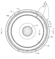
- FIG. 1 The whole perspective view which shows the electric rice cooker as one Embodiment of this invention.
- the top view of the electric rice cooker shown in FIG. The bottom view of the electric rice cooker shown in FIG.
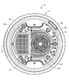
- the IV-IV cross section enlarged view in FIG.
- the electric rice cooker 10 includes a rice cooker 12 for containing rice, water and the like as a material to be cooked, and a rice cooker main body 16 having a pot housing recess 14 for containing the rice cooker 12 in a removable manner.
- the upper side means the upper side in FIGS. 1 and 4 and the lower side means the lower side in FIGS. 1 and 4 and the front means the left side and the rear side in FIGS. Shall mean the right side in FIGS.
- the cooking pot 12 has a pot body 18 made of pottery containing rice, water and the like as a food to be cooked, and a lid which covers the upper opening 20 which is the opening portion of the pot body 18. It is composed of a body 22. Both the pan body 18 and the lid 22 are made of porous pottery having a large number of micro-spaces open on the surface.
- the pot body 18 has a substantially cylindrical peripheral wall portion 24 and a substantially disc-like bottom portion 26 whose diameter increases toward the integrally formed upper opening 20, and has a substantially round pot shape as a whole. ing.
- the thickness dimension of the peripheral wall portion 24 is gradually thickened from the bottom portion 26 toward the upper opening 20, and the middle to upper ends of the circumferential wall portion 24 than the thickness dimension t 1 of the bottom portion 26 Thickness dimension: t2 is larger (t1 ⁇ t2).
- a flange portion 30 is provided at the upper end edge portion 28 of the pan body 18 of the rice cooker 12 so as to protrude in the substantially rectangular cross-sectional shape toward the outer peripheral side and spread over substantially the entire outer peripheral side.
- the bottom surface 32 of the flange portion 30 is provided with a downward slope which protrudes downward as it goes to the outer peripheral side. That is, such downward inclination is configured to approach the bottom wall 112 of the annular groove portion 110 as described later.
- the upper surface 34 of the flange portion 30 is also provided with a downward slope which protrudes downward as it goes to the outer peripheral side.
- step surfaces 36a and 36b having a substantially L-shaped cross-sectional shape are provided over substantially the entire periphery.
- the step surface 36 b is formed below and inward of the step surface 36 a.
- a temperature detection plate 38 is disposed at the central portion of the bottom portion 26 corresponding to the bottom surface of the pot body 18 of the rice cooker 12, and has a cross-sectional shape substantially similar to the temperature detection plate 38.
- the through hole 40 is formed. Since the outer shape of the temperature detection plate 38 and the through hole 40 have a T-like cross-sectional shape that is substantially similar, the temperature detection plate 38 can be stably held in the through hole 40. And while the temperature detection board 38 comprises a part of bottom part 26, while the sensor part 76a of the rice cooker main body 16 mentioned later abuts.
- the temperature detecting plate 38 is made of various metals, metal compounds, carbon, alumina, aluminum nitride or the like, which is a material having a heat transfer coefficient higher than that of the potter body 18 or the pottery constituting the lid 22.
- the temperature in the pan body 18 can be measured more accurately than in the case where the sensor portion 76a of the temperature sensor 76 is in pressure contact with the ceramic surface.
- the outer shape of the temperature detection plate 38 and the through hole 40 have a T-shaped cross-sectional shape that is substantially similar, the shape will be described in detail below taking the temperature detection plate 38 as an example.
- the temperature measuring plate 38 has a large diameter portion 42 on the inner surface side of the bottom portion 26 defining the inner peripheral surface of the pan body 18, and a small diameter portion on the outer surface side of the bottom portion 26 defining the outer peripheral surface of the pan body 18 44 and has a generally stepped cylindrical shape as a whole. Moreover, the step surface 46 between the large diameter portion 42 and the small diameter portion 44 of the temperature detection plate 38 is a downward inclined surface which descends toward the inner peripheral side.
- the above-described shape is a T-shaped cross-sectional shape in which the outer shape of the temperature detection plate 38 and the through hole 40 are similar.
- the temperature detection plate 38 is provided with a housing recess 48 which opens downward at the central portion of the outer surface and stores a sensor portion 76a described later.
- the inner surface 50 of the peripheral wall portion of the housing recess 48 has a tapered surface shape which spreads outward in the radial direction (left and right direction in FIG. 4) as it goes downward.
- the temperature detection plate 38 is formed into a stepped cylindrical shape, the temperature detection plate 38 can be reliably held at the stepped portion with respect to the through hole 40 of the similar shape provided in the bottom portion 26 of the pan body 18. It can be stably disposed at the bottom portion 26 of the pot body 18.
- the housing recess 48 for housing the sensor portion 76a is provided at the central portion of the outer surface, the sensor portion 76a can be stably positioned and held. Further, by providing the housing recess 48, the thickness of the portion where the sensor portion 76a abuts can be reduced, so that the temperature inside the pan body 18 can be detected more reliably.
- the step surface 46 between the large diameter portion 42 and the small diameter portion 44 of the temperature detection plate 38 is a downward inclined surface, the locking portion of the temperature detection plate 38 to the bottom portion 26 of the pan body 18 locally The stress concentration can be eliminated, and in the manufacturing process, the adhesive can be easily poured between the two, and the productivity can also be improved.
- the inner surface 50 of the peripheral wall portion of the housing recess 48 has a tapered surface shape that expands radially outward as it goes downward, the sensor portion 76 a is guided and housed in the housing recess 48. Thus, the temperature measuring plate 38 and the sensor section 76a can be positioned smoothly.
- the lid 22 of the rice cooker 12 is configured to include an inner lid 52 and an outer lid 54.
- the inner lid 52 has a substantially disc shape that spreads flat as a whole, and a columnar handle 56 that protrudes upward is integrally formed at a radial center portion.
- the thickness dimension t3 of the inner lid 52 is larger than the thickness dimension t1 of the bottom 26 and the thickness dimension t4 of the outer lid 54, and the thickness dimension from the middle to the upper end side of the peripheral wall 24: t2 It is smaller than the above (t1 ⁇ t4 ⁇ t3 ⁇ t2).
- a flange-like locking piece 58 extending toward the outer peripheral side over substantially the entire circumference is integrally formed.
- the inner lid 52 is formed with a pressure release hole (not shown) for pressing, which penetrates the inner lid 52 in the thickness direction.
- a plurality of protrusions 60 that project downward in a substantially dome shape are formed. As shown in FIG. 4, the inner lid 52 having such a structure holds the locking piece 58 of the inner lid 52 with the step surface 36 b of the upper end edge portion 28 of the pan main body 18 in a state in which the handle 56 is gripped.
- the upper opening 20 which is an opening of the pan body 18 can be covered by being engaged with the above.
- the outer lid 54 has a generally spherical shell shape as a whole, and a substantially cylindrical handle 62 protruding upward at the radial center portion. Is provided. Further, as shown in FIG. 2, a pressure release hole 64 is formed in the rear (rightward in FIG. 2) of the handle 62 with a substantially circular cross-sectional shape.
- the steam storage space 66 can be formed between the inner lid 52 and the inner lid 52 so as to be installed above the inner lid 52.
- the lid 22 has a double lid structure of the inner lid 52 and the outer lid 54 and the steam storage space 66 is formed between the inner lid 52 and the outer lid 54, it is possible to cook rice The pressure state and soaking inside the pan body 18 can be stably held.
- the inner lid 52 covers the upper opening 20 of the pot body 18 and spreads flatly and is thicker than the outer lid 54, the weight of the inner lid 52 causes the inside of the pot body 18 to be cooked at the time of cooking. The pressurization can be held more reliably, and good rice cooking can be realized.
- the rice cooker body 16 is provided with a pot housing recess 14, and the pot housing recess 14 is a bottom wall 68 and a bottom wall that are substantially circular in a plan view. It is configured to have a peripheral wall portion 70 which protrudes substantially upward in a substantially spherical shape from the outer peripheral edge portion 68 to substantially the entire periphery.
- the bottom wall 68 of the pot housing recess 14 is provided with a sheathed heater 72 as an electric heater for heating the rice cooker 12, and in a through hole 74 formed in the center of the sheathed heater 72.
- a temperature sensor 76 is provided.
- a blower fan 80 Inside the rice cooker body 16 on the bottom surface 78 side of the rice cooker body 16 located below the sheathed heater 72, there are provided a blower fan 80, and a control unit 82 for controlling the blower fan 80 and the sheathed heater 72. There is.
- the sheathed heater 72 has a structure in which a first sheathed heater 72a and a second sheathed heater 72b are held with respect to a sheathed heater holding member 84 having a substantially plate shape as a whole. have.
- the sheathed heater holding member 84 is made of metal, and the upper surface side thereof is substantially similar in shape to the bottom portion 26 of the pan body 18, while the lower surface side accommodates the first sheathed heater 72a and the second sheathed heater 72b.
- a sheathed heater receiving hole 86 for holding the lower end is formed to open downward and extend in a substantially spiral shape in the circumferential direction.
- the sheath heater 72 constituting the electric heater has the substantially disc-shaped first sheathed heater 72a on which the center of the bottom 26 of the pan body 18 is placed, and the periphery of the bottom 26 of the pan body 18 is placed
- the second sheathed heater 72b has a substantially annular shape.
- the sheathed heater 72 is fixed to a predetermined position in the rice cooker body 16 by fixing means (not shown). As a result, by controlling the output of the first sheathed heater 72a and the second sheathed heater 72b in accordance with the process of cooking, it is possible to advantageously adjust the temperature distribution of the pan body 18 at the time of cooking.
- a through hole 74 is provided at the central portion of the sheathed heater 72 that constitutes the bottom wall 68 of the pan housing recess 14, and a temperature sensor 76 is provided in the through hole 74.
- the sensor portion 76a is disposed so as to be extensible and contractible in the vertical direction in a state of being biased upward by an elastic member (not shown) such as a compression coil spring.
- an elastic member such as a compression coil spring.
- the temperature sensor 76 is connected to the temperature sensor support part 90 provided below the temperature sensor 76, the temperature sensor support part 90 is being fixed to the rice cooker main body 16 via the compression coil spring. Further, the temperature sensor 76 is disposed in a state of being protruded upward from the upper opening of the through hole 74. Thus, when the bottom portion 26 of the pan body 18 is placed on the sheathed heater 72, the sensor portion 76a of the temperature sensor 76 is the central portion of the bottom portion 26 of the pan body 18 based on the biasing force of the compression coil spring. The bottom surface of the housing recess 48 of the temperature measuring plate 38 disposed in the housing is in pressure contact.
- the rear side of the rice cooker body 16 located on the bottom surface 78 side, which is located below the sheathed heater 72 that constitutes the bottom wall 68 of the pan housing recess 14 (see FIG. Among the four, the blower fan 80 is provided on the right side), while the control unit 82 made of a circuit board is provided on the front side (the left side in FIG. 4).
- a suction port 92a consisting of a number of substantially strip-like through holes extending substantially in a radial shape over substantially the entire surface.
- the air intakes 92a and 92b allow the outside air to be efficiently introduced into the rice cooker body 16. More specifically, the outside air introduced into the rice cooker body 16 from the air inlet 92a is sent upward to cool the sheathed heater 72 that constitutes the bottom wall portion 68 of the pot housing recess 14, and to be described later The air is exhausted upward through the air passage 102 defined between the recess 14 and the pot body 18.
- the outside air introduced into the rice cooker main body 16 from the air inlet 92b is sent upward to cool the control unit 82 and the sheathed heater 72, and to draw the space between the pot housing recess 14 and the pot body 18 described later.
- the air is exhausted upward through the formed air passage 102.
- a cover 93 made of a substantially rectangular box-shaped synthetic resin is opened above the control unit 82 toward the control unit 82 to prevent the water or the like from being applied to the control unit 82 or the sheathed heater 72.
- leg portions 94 projecting in a substantially solid truncated cone shape are provided at four places separated in the circumferential direction (see FIGS. 3 and 4).
- the peripheral wall portion 70 of the pot housing recess 14 is outwardly with respect to the outer peripheral edge portion 96 of the sheath heater 72 that constitutes the bottom wall portion 68 of the pot housing recess 14. It is formed to project upward in a substantially cylindrical shape whose diameter gradually increases upward from a position spaced apart toward the upper side.
- rubber protrusions 98 projecting inward of the pan housing recess 14 are provided at four places separated at equal intervals in the circumferential direction.
- the rubber projection 98 is brought into pressure contact with the outer peripheral surface of the peripheral wall portion 24 of the pot body 18 in a state where the cooking pot 12 is accommodated in the pot accommodation recess 14, the peripheral wall portion 70 of the pot accommodation recess 14 and the pot
- the pan body 18 is housed in the pan housing recess 14 in a state where a gap of a predetermined size is formed between the pan 18 and the outer peripheral surface of the peripheral wall portion 24 of the main body 18.
- the air gap 102 which spreads in the circumferential direction and the up-and-down direction is formed between the peripheral wall portion 70 of the pot housing recess 14 and the outer peripheral surface of the peripheral wall portion 24 of the pot body 18 by this gap.
- the peripheral wall part 70 is made into the lower peripheral wall part 70b below.
- the upper peripheral wall 70a and the lower peripheral wall 70b constituting the peripheral wall 70 are both made of metal and are separately molded.
- the upper end opening 104 of the air passage 102 is outside at the upper opening 106 of the pan accommodation recess 14.
- the lower end opening 108 of the air flow passage 102 is in communication with the inside of the rice cooker body 16 while being in direct communication with the More specifically, the air blowing passage 102 has an annular shape that spreads over the entire circumference between the peripheral wall portion 70 of the pot housing recess 14 and the outer peripheral surface of the peripheral wall portion 24 of the pot body 18.
- the upper end opening 104 of the air passage 102 is constituted by an upper annular clearance ⁇ formed between the upper end edge of the peripheral wall 70 of the pot housing recess 14 and the upper end edge 28 of the pot body 18.
- the lower annular clearance provided at the lower end opening 108 of the air flow path 102 between the peripheral wall 70 of the pot housing recess 14 and the sheath heater 72 constituting the bottom wall 68 of the pot housing recess 14 It is configured.
- the gap dimension ⁇ between the upper peripheral wall 70 a of the pan housing recess 14 and the peripheral wall 24 of the pan body 18 in the air flow path 102 is expanded toward the upper end opening 104.
- annular recessed groove 110 is opened upward and extends over substantially the entire outer periphery of the upper peripheral wall 70a.
- the outer peripheral side of the upper peripheral wall 70a is provided continuously.
- the annular groove portion 110 is substantially wedge-shaped, and includes a bottom wall 112, an inner circumferential side wall 114a projecting upward from an end edge portion on the inner circumferential side of the bottom wall 112, and an outer circumferential side of the bottom wall 112. And an outer peripheral side wall 114b protruding upward from the end edge.
- the tip of the inner circumferential side wall 114a of the annular groove 110 is connected to the tip of the upper circumferential wall 70a, and the bottom wall 112 is formed below the tip of the upper circumferential wall 70a.
- the tip end portion of the outer peripheral side wall 114b of the annular recessed groove portion 110 protrudes upward beyond the tip end portion of the upper peripheral wall portion 70a, and the cooking pot 12 is accommodated in the pot accommodation recess 14 It is formed so as to be located slightly below the outer peripheral edge of the upper surface 34 of the flange portion 30.
- the outer peripheral end face of the flange portion 30 provided on the upper end edge portion 28 of the pot body 18 is an annular shape of the rice cooker main body 16 provided therebelow It is positioned immediately above the recessed groove portion 110.
- the bottom surface 32 of the flange portion 30 is inclined downward toward the outer peripheral side, it is possible to prevent the blowout etc.
- the outer periphery of the annular groove 110 The tip end of the side wall 114b is formed to be located below the tip end of the upper peripheral wall 70a.
- an operation panel 118 provided with, for example, a liquid crystal display and various touch panel type operation switches is installed. Inside the operation panel 118, a control unit 120 for the operation panel 118 is disposed. In addition, a substantially rectangular box-like synthetic resin cover 122 opening toward the control unit 120 is disposed behind the control unit 120 (rightward in FIG. 4), and water, etc. for the control unit 120 is provided. It is possible to advantageously realize the prevention of the hooking and the shutoff of the heat from the sheathed heater 72.
- the electric rice cooker 10 of the structure according to such this embodiment is used in the state which the rice cooker 12 was accommodated in the pot accommodation recess 14, as FIG. 4 shows. In this state, substantially the entire upper end edge 28 of the pot body 18 and the lid 22 are exposed to the outside at the upper opening 106 of the pot housing recess 14.
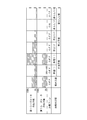
- the process of rice cooking is comprised including a water absorption process, a temperature rising process, a cooking process, and a steaming process, as FIG. 5 shows.
- a water absorption process is performed.
- rice, water and the like as rice to be cooked (not shown) are contained in the pot body 18 of the rice cooker 12 in a state of being accommodated in the pot accommodation recess 14 of the rice cooker body 16. It is done in the state of containing. Since the pot body 18 is made of pottery having low thermal conductivity, the temperature does not easily rise and temperature unevenness easily occurs. Therefore, in the present embodiment, in the water absorption process before the temperature raising process, a preheating operation is performed in which heating is performed in advance. As shown in FIG.
- this preheating operation is carried out by heating the control unit 82 with an output value of, for example, approximately 50% for approximately 20 minutes using both sheathed heaters 72a and 72b in the water absorption process. Ru.
- the time taken for the water absorption process is utilized to heat the pan body 18, and the pot body 18 made of ceramic takes a long time to realize the desired temperature in the pan body 18 from the beginning of the heating process. be able to.
- the control unit 82 causes the blower fan 80 to be in the OFF (non-operation) state.
- a temperature raising step is performed.
- the control unit 82 subsequently executes the heating of the pan body 18 using both sheathed heaters 72a and 72b.
- the output value of the sheathed heater 72a, 72b in the temperature raising step is, for example, 20%, 10% for 5 minutes in the temperature raising (i) (see FIG. 5) at the beginning of the temperature raising step. It is lower than 50% of the output value of 72b.
- the temperature in the pan body 18 is made optimum for cooking by eliminating temperature unevenness using the heat storage property of the pottery. Can.
- the output values of the sheathed heaters 72a and 72b are heated at 90% and 50% for 10 minutes, for example. It is possible to raise the temperature to the optimum temperature. Also in the temperature raising process, the blower fan 80 is in the OFF (non-operation) state by the control unit 82.
- a cooking process is performed after a temperature rising process.
- the control unit 82 is performed by heating the pan body 18 using only the first sheathed heater 72 a.
- the output value in the cooking process of the first sheathed heater 72a is, for example, 40% at 5 minutes in cooking (i) (see FIG. 5) at the beginning of the cooking process, while the output value in the second half of the cooking process In cooking (ii), for example, it is 5 minutes at 20%.
- the cooking process can be performed using only the first sheathed heater 72a on which the center of the bottom portion 26 of the pot body 18 is placed by utilizing the heat storage property of the pot body 18 made of pottery. Therefore, power-saving rice cooking using the heat storage property of the pot body 18 made of pottery is possible.
- the control unit 82 causes the blower fan 80 to be in the OFF (non-operation) state.
- the steaming process is performed after the cooking process.
- the control unit 82 sets the output value of both sheathed heaters 72a and 72b to, for example, 0%. It is about 15 minutes and the blower fan 80 is driven.
- the outside air introduced from the lower end opening 108 of the air flow path 102 can be continuously discharged from the upper end opening 104 without staying in the air flow path 102, so that the entire pan body 18 is cooled. It can be promoted.
- the second half of the steaming process (ii) see FIG.
- the control unit 82 sets only the output value of the first sheathed heater 72a to, eg, 10% for about 5 minutes and turns off the blower fan 80 (not Operation) state.
- the control unit 82 continuously drives the blower fan 80 to continuously pass the outside air to the blower path 102, and at the beginning of the steaming process in which the sheathed heaters 72a and 72b are turned off (i Period (15 minutes) covers over 70% of the total period (15 minutes + 5 minutes) of the steaming process.
- the control unit 82 turns off the sheathed heaters 72a and 72b for a period of 70% or more of the steaming process from the steaming (i) at the beginning of the steaming process and continuously introduces external air into the air passage 102 Can continue to be done. Therefore, heat dissipation of the pot body 18 can be promptly performed to maintain the temperature of the pot body 18 suitable for the steaming process, and it is possible to cook plump delicious rice. Further, as shown in FIG.
- the pot body 18 of the rice cooker 12 is directly connected by the sheath heater 72 provided on the bottom wall portion 68 of the pot housing recess 14 of the rice cooker body 16. It is supposed to be heated. Therefore, as with the traditional pot door, the temperature rise of the pot body 18 gradually due to direct heating of the pot body 18 made of pottery, the soaking at the time of temperature rise, and the heat storage property after heating You can cook rice deliciously by making good use of it. Moreover, since the sheathed heater 72 is used, the control unit 82 can also maintain the convenience of the electric rice cooker 10 such as reserved rice cooking as it is.
- an air passage 102 extending in the circumferential direction and in the vertical direction is formed between the peripheral wall portion 70 of the pot housing recess 14 and the outer peripheral surface of the peripheral wall portion 24 of the pot body 18.
- the lower end opening 108 of the air passage 102 is in communication with the inside of the rice cooker body 16 while the air channel 104 is in direct communication with the outside.
- external air introduced from the lower end opening 108 of the air passage 102 is retained in the air passage 102 only by driving the air blower fan 80 in the steaming process where the heat storage property of the pot body 18 made of ceramics becomes a problem. Since the liquid can be discharged continuously from the upper end opening 104, the entire cooling of the pot body 18 can be promoted.
- the controller 82 has a drying mode.
- the drying step is performed in a state where only the pan body 18 containing rice, water, and the like as the food to be cooked is accommodated in the pan accommodating recess 14 of the rice cooker body 16. More specifically, the drying process is performed so as to promote the drying of the pan body 18 by the control unit 82 driving the sheathed heater 72 and the blower fan 80 that constitute the electric heater. Since the drying of the pot body 18 after use which tends to be carried out can be reliably performed by this drying process, the initial state of the pot body 18 can be maintained, and maintenance and improvement of the durability of the pot body 18 can be achieved. it can.
- the lid 22 of the cooking pot 12 is also made of the same pottery as the pot body 18, but the cover 22 does not necessarily have to be made of pottery. It is possible to use any material such as one made by Meanwhile, earthenware pot body, in order to maintain high heat storage, bulk density or measured by JIS A 1509 is, 1.5g / cm 3 ⁇ 2.3g / cm 3, preferably 2.0 g / cm 3 is a ⁇ 2.1g / cm 3, in the present embodiment has a 2.05g / cm 3 ⁇ 2.08g / cm 3.
- the JIS of the pot body made of pottery The water absorption measured by A 1509 is 6 to 12%, preferably 8 to 10%, and is 9% in this embodiment.
- the sheathed heater 72 is used as the electric heater. However, the sheathed heater 72 is not limited to the sheathed heater, and a known electric heater such as a ceramic heater or a carbon heater can be adopted.
- the output value of the first sheathed heater 72a is, for example, about 5 minutes at 10% and the blower fan 80 is in the OFF (non-operational) state
- the latter half of the steaming process is steamed
- a step of turning off both sheathed heaters 72a and 72b without driving the blower fan 80 in (ii) may be incorporated to discharge excess water.
- the continuous driving of the blower fan 80 and the OFF state of both sheathed heaters 72a and 72b may be maintained throughout the steaming process.
- the embodiment of the present invention includes an embodiment in which rice is cooked by performing forced cooling by the blower fan 80 in the steaming step.
- the second sheathed heater 72b is turned off in the cooking process, and only the first sheathed heater 72a is used.
- the first sheathed heater 72a and the second sheathed heater 72a are used according to cooking preference. It can be modified to use at least one of the heaters 72b. That is, in the cooking process, the first sheathed heater 72a may be turned off and only the second sheathed heater 72b may be used, or both the first and second sheathed heaters 72a and 72b may be used. .
Landscapes
- Engineering & Computer Science (AREA)
- Food Science & Technology (AREA)
- Cookers (AREA)
- Glass Compositions (AREA)
- Thermally Insulated Containers For Foods (AREA)
Priority Applications (3)
| Application Number | Priority Date | Filing Date | Title |
|---|---|---|---|
| KR1020207012526A KR102351771B1 (ko) | 2017-10-27 | 2018-10-26 | 전기 밥솥 |
| CN201880070233.5A CN111278334A (zh) | 2017-10-27 | 2018-10-26 | 电饭锅 |
| CN202510847097.8A CN120753507A (zh) | 2017-10-27 | 2018-10-26 | 电饭锅 |
Applications Claiming Priority (2)
| Application Number | Priority Date | Filing Date | Title |
|---|---|---|---|
| JP2017208160A JP6553151B2 (ja) | 2017-10-27 | 2017-10-27 | 電気炊飯器 |
| JP2017-208160 | 2017-10-27 |
Publications (1)
| Publication Number | Publication Date |
|---|---|
| WO2019083005A1 true WO2019083005A1 (ja) | 2019-05-02 |
Family
ID=66247919
Family Applications (1)
| Application Number | Title | Priority Date | Filing Date |
|---|---|---|---|
| PCT/JP2018/039831 Ceased WO2019083005A1 (ja) | 2017-10-27 | 2018-10-26 | 電気炊飯器 |
Country Status (5)
| Country | Link |
|---|---|
| JP (1) | JP6553151B2 (enExample) |
| KR (1) | KR102351771B1 (enExample) |
| CN (2) | CN120753507A (enExample) |
| TW (1) | TWI772541B (enExample) |
| WO (1) | WO2019083005A1 (enExample) |
Cited By (1)
| Publication number | Priority date | Publication date | Assignee | Title |
|---|---|---|---|---|
| EP4154773A1 (en) * | 2021-09-24 | 2023-03-29 | Norqi ApS | Electrically heated cooking device |
Families Citing this family (6)
| Publication number | Priority date | Publication date | Assignee | Title |
|---|---|---|---|---|
| JP7227490B2 (ja) * | 2019-05-27 | 2023-02-22 | タイガー魔法瓶株式会社 | 炊飯器 |
| JP7161244B1 (ja) * | 2021-06-18 | 2022-10-26 | シロカ株式会社 | 加熱調理器 |
| JP7262828B2 (ja) * | 2021-07-20 | 2023-04-24 | シロカ株式会社 | 加熱調理器 |
| JP7195657B1 (ja) * | 2021-08-02 | 2022-12-26 | シロカ株式会社 | 加熱調理器、及び、プログラム |
| JP7531532B2 (ja) * | 2022-01-05 | 2024-08-09 | 三菱電機株式会社 | 内釜および炊飯器 |
| JP7772610B2 (ja) * | 2022-02-10 | 2025-11-18 | 東芝ホームテクノ株式会社 | 炊飯器 |
Citations (8)
| Publication number | Priority date | Publication date | Assignee | Title |
|---|---|---|---|---|
| JPH02274207A (ja) * | 1989-04-17 | 1990-11-08 | Hitachi Home Tec Ltd | 加熱調理器 |
| JPH03261415A (ja) * | 1990-03-12 | 1991-11-21 | Matsushita Electric Ind Co Ltd | 炊飯器 |
| JPH09248242A (ja) * | 1996-03-15 | 1997-09-22 | Tiger Vacuum Bottle Co Ltd | 電気炊飯器 |
| JPH10262817A (ja) * | 1997-03-22 | 1998-10-06 | Paloma Ind Ltd | ガス炊飯器 |
| JP2007044306A (ja) * | 2005-08-10 | 2007-02-22 | Mitsubishi Electric Corp | 加熱調理器およびその鍋状容器の乾燥方法 |
| JP2007252624A (ja) * | 2006-03-23 | 2007-10-04 | Tiger Vacuum Bottle Co Ltd | 電気炊飯器 |
| JP2009273743A (ja) * | 2008-05-16 | 2009-11-26 | Rinnai Corp | 調理鍋 |
| JP2009293806A (ja) * | 2008-06-02 | 2009-12-17 | Nagatani Seito Kk | 加熱調理器とそれを構成するカバー部材 |
Family Cites Families (3)
| Publication number | Priority date | Publication date | Assignee | Title |
|---|---|---|---|---|
| JPS4910441B1 (enExample) | 1968-01-05 | 1974-03-11 | ||
| KR101632742B1 (ko) * | 2014-05-28 | 2016-06-22 | 정원식 | 인덕션 조리기 |
| CN204698350U (zh) * | 2015-05-13 | 2015-10-14 | 黄俊杰 | 双层锅盖的陶瓷锅 |
-
2017
- 2017-10-27 JP JP2017208160A patent/JP6553151B2/ja active Active
-
2018
- 2018-10-19 TW TW107136939A patent/TWI772541B/zh active
- 2018-10-26 CN CN202510847097.8A patent/CN120753507A/zh active Pending
- 2018-10-26 KR KR1020207012526A patent/KR102351771B1/ko active Active
- 2018-10-26 CN CN201880070233.5A patent/CN111278334A/zh active Pending
- 2018-10-26 WO PCT/JP2018/039831 patent/WO2019083005A1/ja not_active Ceased
Patent Citations (8)
| Publication number | Priority date | Publication date | Assignee | Title |
|---|---|---|---|---|
| JPH02274207A (ja) * | 1989-04-17 | 1990-11-08 | Hitachi Home Tec Ltd | 加熱調理器 |
| JPH03261415A (ja) * | 1990-03-12 | 1991-11-21 | Matsushita Electric Ind Co Ltd | 炊飯器 |
| JPH09248242A (ja) * | 1996-03-15 | 1997-09-22 | Tiger Vacuum Bottle Co Ltd | 電気炊飯器 |
| JPH10262817A (ja) * | 1997-03-22 | 1998-10-06 | Paloma Ind Ltd | ガス炊飯器 |
| JP2007044306A (ja) * | 2005-08-10 | 2007-02-22 | Mitsubishi Electric Corp | 加熱調理器およびその鍋状容器の乾燥方法 |
| JP2007252624A (ja) * | 2006-03-23 | 2007-10-04 | Tiger Vacuum Bottle Co Ltd | 電気炊飯器 |
| JP2009273743A (ja) * | 2008-05-16 | 2009-11-26 | Rinnai Corp | 調理鍋 |
| JP2009293806A (ja) * | 2008-06-02 | 2009-12-17 | Nagatani Seito Kk | 加熱調理器とそれを構成するカバー部材 |
Cited By (1)
| Publication number | Priority date | Publication date | Assignee | Title |
|---|---|---|---|---|
| EP4154773A1 (en) * | 2021-09-24 | 2023-03-29 | Norqi ApS | Electrically heated cooking device |
Also Published As
| Publication number | Publication date |
|---|---|
| CN111278334A (zh) | 2020-06-12 |
| JP6553151B2 (ja) | 2019-07-31 |
| KR102351771B1 (ko) | 2022-01-18 |
| KR20200066658A (ko) | 2020-06-10 |
| TW201922154A (zh) | 2019-06-16 |
| JP2019076661A (ja) | 2019-05-23 |
| TWI772541B (zh) | 2022-08-01 |
| CN120753507A (zh) | 2025-10-10 |
Similar Documents
| Publication | Publication Date | Title |
|---|---|---|
| WO2019083005A1 (ja) | 電気炊飯器 | |
| JP2019076661A5 (enExample) | ||
| JP5025154B2 (ja) | 電気炊飯器 | |
| JP2004065553A (ja) | 加熱調理器 | |
| JP2011024810A (ja) | 電磁調理用容器 | |
| TWM538765U (zh) | 電子鍋 | |
| JP4416714B2 (ja) | 圧力加熱調理器 | |
| JP5316524B2 (ja) | 電気炊飯器 | |
| JP2794684B2 (ja) | 電気釜 | |
| JP2004065536A (ja) | 加熱調理器 | |
| JP2004065766A (ja) | 調理容器および調理器 | |
| KR101754358B1 (ko) | 휴대용 전기 조리기기 | |
| JP6197167B2 (ja) | 電気炊飯器 | |
| JP6161585B2 (ja) | 電気炊飯器 | |
| JP2005174705A (ja) | 加熱調理器 | |
| CN119212128A (zh) | 烹饪器具的烹饪控制方法和烹饪器具 | |
| JP3933088B2 (ja) | 誘導加熱調理器 | |
| CN218899194U (zh) | 一种均衡温度的锅盖 | |
| JP2003325323A (ja) | 調理容器および調理器 | |
| CN216147790U (zh) | 一种不粘电热锅 | |
| JP5527459B2 (ja) | 電気炊飯器 | |
| JP6369138B2 (ja) | 電気炊飯器 | |
| CN213605920U (zh) | 一种电烤炉 | |
| CN100487323C (zh) | 微波炉用辅助容器 | |
| JP2006031947A (ja) | 電磁誘導加熱調理器 |
Legal Events
| Date | Code | Title | Description |
|---|---|---|---|
| 121 | Ep: the epo has been informed by wipo that ep was designated in this application |
Ref document number: 18870517 Country of ref document: EP Kind code of ref document: A1 |
|
| NENP | Non-entry into the national phase |
Ref country code: DE |
|
| ENP | Entry into the national phase |
Ref document number: 20207012526 Country of ref document: KR Kind code of ref document: A |
|
| 122 | Ep: pct application non-entry in european phase |
Ref document number: 18870517 Country of ref document: EP Kind code of ref document: A1 |