WO2019077985A1 - 溶接システムに用いられる表示システム - Google Patents
溶接システムに用いられる表示システム Download PDFInfo
- Publication number
- WO2019077985A1 WO2019077985A1 PCT/JP2018/036687 JP2018036687W WO2019077985A1 WO 2019077985 A1 WO2019077985 A1 WO 2019077985A1 JP 2018036687 W JP2018036687 W JP 2018036687W WO 2019077985 A1 WO2019077985 A1 WO 2019077985A1
- Authority
- WO
- WIPO (PCT)
- Prior art keywords
- inching
- unit
- welding
- display
- wire
- Prior art date
- Legal status (The legal status is an assumption and is not a legal conclusion. Google has not performed a legal analysis and makes no representation as to the accuracy of the status listed.)
- Ceased
Links
Images





Classifications
-
- B—PERFORMING OPERATIONS; TRANSPORTING
- B23—MACHINE TOOLS; METAL-WORKING NOT OTHERWISE PROVIDED FOR
- B23K—SOLDERING OR UNSOLDERING; WELDING; CLADDING OR PLATING BY SOLDERING OR WELDING; CUTTING BY APPLYING HEAT LOCALLY, e.g. FLAME CUTTING; WORKING BY LASER BEAM
- B23K9/00—Arc welding or cutting
- B23K9/10—Other electric circuits therefor; Protective circuits; Remote controls
-
- B—PERFORMING OPERATIONS; TRANSPORTING
- B23—MACHINE TOOLS; METAL-WORKING NOT OTHERWISE PROVIDED FOR
- B23K—SOLDERING OR UNSOLDERING; WELDING; CLADDING OR PLATING BY SOLDERING OR WELDING; CUTTING BY APPLYING HEAT LOCALLY, e.g. FLAME CUTTING; WORKING BY LASER BEAM
- B23K9/00—Arc welding or cutting
- B23K9/12—Automatic feeding or moving of electrodes or work for spot or seam welding or cutting
Definitions
- the present disclosure relates to a display system used for a consumable electrode welding system.
- the present disclosure relates to a display system that displays the delivery status of welding wires.
- inching is performed, for example, as a preparation before the start of welding (see, for example, Patent Document 1).
- the welding wire is unwound from the wire feeding device and fed (continuously or intermittently) until the tip of the wire protrudes from the abutment torch.
- the operator turns on the inching switch to start feeding the welding wire, and then turns off the inching switch when it visually confirms that the welding wire has come out of the tip of the welding torch. Finish.
- hollow wire feeding cables are used to feed welding wires.
- the welding wire is passed through the wire feeding cable and fed from the wire feeding device to the welding torch.
- the wire feed cable is opaque. Therefore, the operator does not know the feeding condition of the welding wire at the time of inching (for example, where the tip of the welding wire is in the wire feeding cable). Therefore, when judging the stop timing of inching visually, the inching switch can not be turned off at an appropriate timing, and the welding wire may come out too much from the tip of the welding torch.
- the distance between the wire feeding device and the welding torch is long (for example, 10 m or more), the wire feeding speed may be increased from the viewpoint of working efficiency. In that case, it becomes more difficult to turn off the inching switch at an appropriate timing.
- the display system provided by the first aspect of the present disclosure is, for example, a configuration suitable for a welding system comprising a wire feeding device provided with a feed motor for feeding a welding wire to a welding torch.
- the same display system an operation unit that receives an inching execution operation and a stop operation, an inching command unit that commands driving of the feed motor when the operation unit receives an inching execution operation, and inching is started And a display unit for displaying an integrated feed amount of the welding wire from time to time.
- a welding torch comprising the display system according to the first aspect.
- a wire feeding device comprising the display system according to the first aspect.
- a relay apparatus comprising the display system according to the first aspect.
- the relay device is disposed in the middle of the guiding path of the welding wire from the wire feeding device to the welding torch.
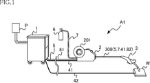
- FIG. 1 and 2 show a welding system A1 according to a first embodiment.
- FIG. 1 is a schematic view showing an entire configuration of a welding system A1.
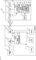
- FIG. 2 is a block diagram showing a functional configuration of welding system A1.
- Welding system A1 includes, for example, welding power supply 1, wire feeder 2, welding torch 3, power cables 41 and 42, power transmission line 5, gas cylinder 6, gas piping 7, and signal lines 81 and 82. There is.
- a torch cable 308 extends from the welding torch 3, and the power transmission line 5, the gas pipe 7, the power cable 41, and the signal line 82 are disposed also in the same cable.
- welding power supply device 1 converts AC power input from power system P, and outputs the converted power from a pair of output terminals.
- one output terminal of the welding power supply device 1 is connected to the welding torch 3 via the power cable 41, and the other output terminal is connected to the workpiece W via the power cable 42.
- the wire feeding device 2 feeds the welding wire to the welding torch 3.
- the delivered welding wire passes through the inside of the welding torch 3 and then protrudes from the tip of the welding torch 3 to the outside.
- a contact tip is disposed inside the tip of the welding torch 3, and the power cable 41 and the welding wire are electrically connected via the contact tip.
- the illustrated welding system A1 is configured to perform gas shield welding.
- the shield gas is supplied from the gas cylinder 6 to the tip of the welding torch 3 through the gas pipe 7.
- the gas pipe 7 is disposed so as to extend from the gas cylinder 6 directly to the wire feeding device 2. Instead of this, the gas pipe 7 may pass through the welding power supply 1 in addition to the wire feeding device 2.
- Welding system A1 may be provided with a cooling mechanism for cooling welding torch 3.
- the cooling mechanism can be configured, for example, to circulate cooling water via the welding torch 3.
- the welding power supply 1 outputs the power required for arc welding. Specifically, for example, three-phase AC power is input from the power system P to the welding power supply 1. Welding power supply device 1 converts the three-phase AC power into a power suitable for arc welding, and outputs the converted power from the pair of terminals described above. Further, welding power supply device 1 converts three-phase AC power input from power system P into power suitable for driving wire feeding device 2, and transmits the converted power via wire 5 via wire transmission line 5. Supply to the feeder 2
- the welding power supply 1 is controlled to output power in accordance with various setting conditions including welding conditions. Each setting condition can be input or changed by the operation of the operation means (not shown) provided in the welding power supply 1. Further, welding power supply device 1 changes the setting conditions in accordance with a signal input from welding torch 3 via signal lines 81 and 82.
- the wire feeding device 2 feeds the welding wire to the welding torch 3.
- the wire feeding device 2 is operated by the power supplied from the welding power supply 1 via the power transmission line 5.
- the wire reel 201 is removably attached to the wire feeding device 2.
- a welding wire is wound around the wire reel 201.
- the wire feeding device 2 is configured to draw the welding wire from the wire reel 201 and guide the wire through the torch cable 308 and the inside of the welding torch 3 to the tip of the welding torch 3.
- a wire feeding liner is provided inside the welding torch 3 and the welding wire is fed through the inside of the liner.
- the wire feeding device 2 has a connector 202 for connecting a torch cable 308 of the welding torch 3.
- the connector 202 is, for example, a concave terminal, into which a convex plug provided at one end of the torch cable 308 is inserted. Thereby, the welding torch 3 and the wire feeding device 2 are connected.
- a power transmission line 5, a gas pipe 7, a power cable 41 and a signal line 82 are disposed inside the wire feeding device 2.
- the power transmission line 5, the gas pipe 7, the power cable 41 and the signal line 82 are disposed.
- the power transmission line 5, the gas pipe 7, the power cable 41, and the signal line 82 in the torch cable 308 are respectively It is connected to the power transmission line 5, the gas pipe 7, the power cable 41 and the signal line 82 in the wire feeding device 2. It is noted that only signal line 82 is depicted as extending through torch cable 308 in FIG. Further, although not shown in the drawing, liners for smoothly feeding the wires are provided in the feeding cable and the torch cable 308 in the wire feeding device 2. These liners are also connected to one another when the torch cable 308 is connected to the wire feeder 2.
- the wire feeding device 2 includes a feeding motor 21, a detection unit 22, a first communication unit 231, a second communication unit 232, a control unit 24, and a storage unit 25 as shown in the functional block of FIG. There is.
- the feed motor 21 generates a driving force for feeding the welding wire.
- the feed motor 21 is driven by the control unit 24 (drive unit 241).
- a feed roll is attached to the rotation shaft of the feed motor 21.
- the rotational force of the feed motor 21 may be transmitted to the feed roll via one or more gears.
- the welding wire contacts the feed roll, and is fed in a predetermined direction by rotation of the feed roll.
- a pressure handle or a pressure roll may be used to reliably feed the welding wire.
- the welding wire may be smoothly supplied to the liner in the torch cable 308.
- the detection unit 22 detects the rotational speed of the feed motor 21.
- the detection unit 22 detects the speed of the feed motor 21 based on, for example, any one of an armature voltage for controlling the speed of the feed motor 21, a detection value of an encoder attached to the feed motor 21, and a detection value of a hall element.
- the detection unit 22 includes a rotary encoder.
- the rotary encoder generates encoder pulses according to the rotation of the feed motor 21.
- the detection unit 22 detects the rotational speed of the feed motor 21 according to the encoder pulse.
- the detection unit 22 outputs (the signal corresponding to) the detected rotational speed to the control unit 24.
- the first communication unit 231 communicates with the welding power supply 1 via the signal line 81.
- the first communication unit 231 transmits a signal input from the control unit 24 to the welding power supply device 1, and outputs a signal received from the welding power supply device 1 to the control unit 24.
- the first communication unit 231 performs wired communication using the welding power supply 1 and the signal line 81, but instead, between the first communication unit 231 and the welding power supply 1, Wireless communication may be performed.
- the second communication unit 232 communicates with the welding torch 3 via the signal line 82.
- the signal line 82 is provided inside the torch cable 308 between the wire feeding device 2 and the welding torch 3.
- the second communication unit 232 transmits a signal input from the control unit 24 to the welding torch 3, and outputs a signal received from the welding torch 3 to the control unit 24.
- the second communication unit 232 performs wired communication using the welding torch 3 and the signal line 82, but instead, wireless communication is performed between the second communication unit 232 and the welding torch 3 May be performed.
- the control unit 24 controls the wire feeding device 2.
- the control unit 24 is realized by, for example, a microcomputer.
- the control unit 24 controls the wire feeding device 2 based on operation signals of operation means (not shown) provided in the wire feeding device 2 and various signals input from the first communication unit 231 and the second communication unit 232. Control each part of In addition, the control unit 24 transmits various signals to the welding power supply 1 via the first communication unit 231, and transmits various signals to the welding torch 3 via the second communication unit 232.
- the control unit 24 includes the drive unit 241, the feed speed calculation unit 242, and the feed amount calculation unit 243, but the present disclosure is not limited thereto.
- the drive unit 241 controls the feed of the welding wire to the welding torch 3 by controlling the drive of the feed motor 21.
- the drive unit 241 drives the feed motor 21 by inputting a drive signal to the feed motor 21.
- the drive unit 241 drives the feed motor 21 in accordance with a welding execution signal (described later) or an inching signal (described later) input from the second communication unit 232 to the control unit 24.
- the feed speed calculation unit 242 calculates the feed speed of the welding wire that is actually fed (hereinafter referred to as "the actual feed speed").
- the feed speed calculation unit 242 calculates the actual feed speed of the welding wire from the rotational speed detected by the detection unit 22 using a predetermined arithmetic expression. For example, the feed speed calculation unit 242 calculates an actual feed speed at predetermined intervals.
- the feed amount calculation unit 243 calculates the feed amount of the welding wire (hereinafter, referred to as “inching integrated feed amount”) actually fed from the start of the inching to the current point (calculation time). For example, the delivery amount calculation unit 243 calculates the inching integrated delivery amount by time-integrating the actual delivery speed. Specifically, the delivery amount calculation unit 243 multiplies the actual delivery speed calculated by the delivery speed calculation unit 242 for each predetermined time interval (“predetermined interval”) by the predetermined interval. The amount of feed (hereinafter referred to as "the amount of actual feed”) of the welding wire actually fed is calculated at predetermined intervals. The calculated actual feed amount is added to the inching integrated feed amount stored in the storage unit 25.
- predetermined interval predetermined time interval
- the inching integrated feed amount from the start of inching to the current time is stored in the storage unit 25.
- the method of calculating the inching integrated feed amount is not limited to the one described above.
- the feed amount calculation unit 243 stores, in the storage unit 25, the actual feed speed at predetermined intervals input from the feed speed calculation unit 242 after the start of inching. Then, the inching integrated feed amount may be calculated by time integration of the actual feed speed from the start of the stored inching to the current time. Generally, the shorter the predetermined interval, the more accurately the amount of welding wire fed can be calculated.
- the storage unit 25 stores information necessary for performing various controls of the wire feeding device 2.
- the storage unit 25 is controlled by the control unit 24 to write and read information.
- the storage unit 25 stores an inching cumulative feed amount and a target feed speed at the time of inching (hereinafter referred to as “target inching speed”).
- the inching integrated feeding amount stored in the storage unit 25 is set to an initial value (for example, zero) by the control unit 24 when a predetermined condition is satisfied.
- the predetermined condition is, for example, a condition that can be determined that one inching operation has been completed.
- the control unit 24 sets the inching integrated feed amount stored in the storage unit 25 to an initial value.
- the inching integrated feed amount is initialized every time one inching operation is completed, so the inching integrated feed amount is added from zero at the next inching.
- the control unit 24 when the inching signal is input from the second communication unit 232, the control unit 24 performs the process described below. That is, when an inching signal is input from the second communication unit 232 to the control unit 24, the drive unit 241 drives the feed motor 21 in accordance with the input inching signal. When the feed motor 21 is driven, the detection unit 22 detects the rotational speed of the feed motor 21. Then, the feed speed calculation unit 242 calculates an actual feed speed from the rotational speed, and the feed amount calculation unit 243 calculates an inching integrated feed amount from the actual feed speed. The calculated actual feed speed and inching integrated feed amount are transmitted from the control unit 24 to the welding torch 3 via the second communication unit 232.
- the drive unit 241 performs feedback control so that the actual feed speed at predetermined intervals calculated by the feed speed calculation unit 242 becomes the target inching speed. Further, at the time of welding, the drive unit 241 performs feedback control so that the target feed speed set at the time of welding is achieved. The drive unit 241 performs feedback control so that the actual feed amount calculated at each predetermined interval calculated by the feed amount calculation unit 243 becomes the target feed amount set at the time of inching and at each time of welding. Good.
- the welding torch 3 welds the workpiece W by the welding power supplied from the welding power supply 1.
- the welding torch 3 is operated by the power supplied from the welding power supply 1 via the power transmission line 5.
- the welding torch 3 may be equipped with a secondary battery, and the welding torch 3 may be operated using the power stored in the secondary battery.
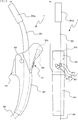
- FIG. 3 is a view showing an appearance of an example of the welding torch 3, (a) is a side view, and (b) is a top view.
- the welding torch 3 includes a torch body 301, a handle 302, a control substrate 303, a display 304, a torch switch 305, an inching switch 306, a plurality of operation buttons 307, and a torch cable 308.
- the torch body 301 is a cylindrical member made of metal, and a liner (through which a welding wire is inserted), a power cable 41, and a gas pipe 7 are disposed inside.
- the torch body 301 has a portion (outer portion) projecting outward from the handle 302 and a portion (inner portion) disposed inside the handle 302.
- a nozzle 301 a is attached to the tip of the outer portion of the torch body 301.
- the torch body 301 is curved so that the operator can easily direct the nozzle 301 a to the workpiece W.
- the outer portion of the torch body 301 is curved so as to easily direct the nozzle 301 a to the workpiece W, but the present disclosure is not limited thereto.
- the handle 302 is a portion for the operator to hold, and is provided to hold the proximal end portion (the above-mentioned inner portion) of the torch body 301.
- the operator holds the handle 302 to perform a welding operation.
- a display 304, a torch switch 305, an inching switch 306, and an operation button 307 are disposed on the handle 302, a control board 303 is disposed inside the handle 302, a control board 303 is disposed inside the handle 302.
- the display 304 performs various displays.
- the display 304 is disposed on the opposite side of the torch switch 305, as shown in FIG. 3 (a).
- the torch switch 305 is an operation means for selectively switching between execution and stop of welding.
- the torch switch 305 functions as an interface for receiving a welding execution operation (command) and a welding stop operation (command) from the operator.
- the torch switch 305 is attached to the handle 302, and is disposed at a position where the operator who grips the handle 302 can easily press and operate the forefinger.
- the torch switch 305 is configured of a push switch. For example, when the torch switch 305 is pressed, welding is performed, and when the pressing is released, the welding is stopped. Specifically, when the torch switch 305 is pressed, welding power is output and a welding wire is fed. On the other hand, when the depression of the torch switch 305 is released, the output of the welding power is stopped and the feeding of the welding wire is stopped. Thus, the operator can perform and stop welding by operating the torch switch 305.
- the inching switch 306 is an operation means for selectively switching between execution and stop of inching.
- the inching switch 306 functions as an interface that receives the inching execution operation (command) and the inching stop operation (command) from the operator.
- the inching switch 306 is attached to the handle 302.
- the inching switch 306 is configured of a push switch. For example, when the inching switch 306 is pressed, inching is performed, and when the pressing is released, the inching is stopped. In the present embodiment, inching is performed only while the inching switch 306 is in the depressed state. Alternatively, inching may be performed continuously by pressing the inching switch 306 once (that is, even if the switch is released immediately after the depression).
- the inching may be stopped by pressing the inching switch 306 again.
- the operator can execute and stop inching by operating the inching switch 306.
- the inching switch 306 may not be a push switch, but may be another switch such as a toggle switch or a rocker switch.
- the operation button 307 is an operation unit for performing an operation of switching the screen or changing various setting values.
- the operation button 307 is disposed on the same side of the handle 302 as the display 304 and between the grip portion of the handle 302 and the display 304.
- the operation button 307 includes an upper button 307a, a lower button 307b, a left button 307c, and a right button 307d.
- the left button 307 c and the right button 307 d are, for example, operation means for switching the screen displayed on the display 304.
- the upper button 307 a and the lower button 307 b are, for example, operation means for changing setting values displayed on the display 304.
- the operator can set, for example, welding conditions, a target inching speed, and a target value of the inching integrated feed amount by operating the plurality of operation buttons 307.
- a sensor that detects pressing of each operation button 307 is mounted on the control board 303. Further, the display 304 is disposed on the same control substrate 303. The display screen of the display 304 is arranged to have a predetermined angle with respect to the control board 303 so that the operator can easily operate the operation buttons 307 while looking at the display screen of the display 304. Alternatively, the display 304 may be arranged such that the display screen is parallel to the control substrate 303.
- the appearance of the welding torch 3 is not limited to that shown in FIG.
- the arrangement places and shapes of the display 304, the torch switch 305, the inching switch 306, and each operation button 307 are not limited to the illustrated example.
- the plurality of operation buttons 307 independent of one another, for example, one cross button may be used.
- inching may be executed by operating the operation button 307.
- the welding torch 3 includes a communication unit 31, a display unit 32, an operation unit 33, a storage unit 34, and a control unit 35.
- the circuits constituting the communication unit 31, the display unit 32, the operation unit 33, the storage unit 34, and the control unit 35 are mounted on a control board 303 (FIG. 3).
- the communication unit 31 communicates with the wire feeding device 2.
- the communication unit 31 transmits the signal input from the control unit 35 to the wire feeding device 2 via the signal line 82 inside the torch cable 308. Further, the communication unit 31 receives a signal input from the wire feeding device 2 through the signal line 82 inside the torch cable 308 and outputs the signal to the control unit 35.
- CAN Controller Area Network
- the communication unit 31 performs wired communication using the wire feeding device 2 and the signal line 82. Instead of this, wireless communication may be performed between the communication unit 31 and the wire feeding device 2.
- the display unit 32 is a unit for performing various displays, and is configured to cooperate with, for example, a liquid crystal display type display 304.
- the display unit 32 and the display 304 function integrally and may not be clearly distinguished. Therefore, in the present specification, any of the cases including and excluding the display 304 may be simply referred to as the “display”.
- the display unit 32 is controlled by the control unit 35.
- the display unit 32 (display 304) displays the welding conditions stored in the storage unit 34.
- the display unit 32 sets the welding wire inching integrated feed amount, the target value of the welding wire inching integrated feed amount, and the current feed speed of the welding wire (actual feed) during inching. Display speed etc.
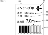
- FIG. 4 shows an example of a screen displayed on the display 304 during inching.
- an icon display S1 showing that inching is in progress
- a numerical value display S2 showing the actual feed speed of the welding wire
- a numerical value showing the target value of the inching integrated feed amount at inching A display S3, a numerical display S4 indicating the inching integrated feed amount of the welding wire up to the present time, and a graphic display S5 indicating the inching integrated feed amount and the target value thereof are displayed.
- a plurality of vertically elongated square marks are arranged.
- the operating portion 33 (FIG. 2) of the welding torch 3 cooperates with a plurality of operating means.
- the operation unit 33 When the operator operates each operation means, the operation unit 33 outputs an operation signal corresponding to the operation to the control unit 35.
- the plurality of operation means are, for example, a torch switch 305, an inching switch 306, and a plurality of operation buttons 307. Therefore, the operation unit 33 outputs, to the control unit 35, an operation signal according to the operation of the torch switch 305, an operation signal according to the operation of the inching switch 306, and an operation signal according to the operation of each operation button 307.
- the storage unit 34 stores setting values such as welding conditions.
- the storage unit 34 stores the target inching speed and the target value of the inching integrated feed amount.
- the target value of the inching cumulative feed amount is preset based on the length of the torch cable 308, for example. Note that the target value of the inching integrated feed amount may be changeable by the operation of the operation button 307 (and thus the operation unit 33 functioning in accordance with the operation).
- the control unit 35 controls the welding torch 3 and is realized by, for example, a microcomputer.
- the control unit 35 performs predetermined processing in accordance with various operation signals input from the operation unit 33. Further, the control unit 35 controls the communication by the communication unit 31, the writing and reading of the information in the storage unit 34, and the display on the display unit 32.
- the control unit 35 includes, for example, a welding command unit 351, an inching command unit 352, a setting unit 353, an information acquiring unit 354, and an image creating unit 355, but the present disclosure is not limited thereto.
- the welding command unit 351 When an operation signal corresponding to the operation of the torch switch 305 is input to the control unit 35, the welding command unit 351 generates a welding execution signal according to the operation signal.
- the welding execution signal is, for example, turned on when the torch switch 305 is pressed and the welding execution operation is performed, and the pressing is released and is turned off when the welding stop operation is performed.
- the generated welding execution signal is transmitted to the wire feeding device 2 and the welding power source device 1 via the communication unit 31.
- the welding command unit 351 causes the wire feeding device 2 to drive the feeding motor 21 to feed the welding wire, and causes the welding power source device 1 to output welding power.
- welding execution signal when the welding execution signal is in the on state, welding wire feeding and welding power output are performed, and when the welding execution signal is in the off state, welding wire feeding and welding power output is I can not do it.
- the inching command unit 352 When the operation signal according to the operation of the inching switch 306 is input from the operation unit 33 to the control unit 35, the inching command unit 352 generates an inching signal according to the operation signal.
- the inching signal is turned on, for example, when the inching switch 306 is pressed (the inching execution operation is performed), and is off when the pressing is released (the inching stop operation is performed). It becomes.
- the generated inching signal is transmitted to the wire feeding device 2 through the communication unit 31.
- the inching command unit 352 causes the wire feeding device 2 to drive the feeding motor 21 to feed the welding wire.
- the welding wire is fed when the inching signal is in the on state, and the welding wire is not fed when the inching signal is in the off state.
- the signal may indicate only the start and stop of inching.
- the wire feeding device 2 receives the signal instructing the start, the feeding of the welding wire is started, and the feeding of the welding wire is continued until the signal instructing the stop is received.
- the setting unit 353 When an operation signal corresponding to the operation of each operation button 307 is input from the operation unit 33 to the control unit 35, the setting unit 353 performs a predetermined setting process according to the operation signal.
- the predetermined setting process is, for example, a process of setting a welding condition, a process of setting a target inching speed, and a process of setting a target value of the inching integrated feed amount.
- the setting unit 353 As the setting process of the welding condition, the setting unit 353 generates a welding condition setting signal for changing the setting of the welding condition, and transmits the generated signal to the welding power supply 1.
- Welding power supply device 1 changes the set value of the welding condition in accordance with the received welding condition setting signal.
- the setting unit 353 As setting processing of the target inching speed, the setting unit 353 generates an inching speed setting signal for setting the target inching speed, and transmits the generated signal to the wire feeding device 2.
- the wire feeding device 2 changes the set value of the target inching speed stored in the storage unit 25 in accordance with the received inching speed setting signal.
- the inching speed setting signal may be a signal (net value signal) indicating the setting value itself of the target inching speed, or may be a signal (difference value signal) for increasing or decreasing the setting value.
- the setting unit 353 changes the target value of the inching integrated feed amount stored in the storage unit 34.
- the setting unit 353 functions as a “setting command unit” that causes a related apparatus or unit to perform predetermined settings.
- the information acquisition unit 354 acquires predetermined information from the wire feeding device 2 via the communication unit 31.
- the information acquisition unit 354 acquires an actual feed speed and an inching integrated feed amount during inching. Whether or not inching is in progress is determined whether an operation signal corresponding to the operation of the inching switch 306 is input from the operation unit 33 to the control unit 35, or the inching signal generated by the inching command unit 352 is in the on state It can be determined based on whether or not
- the image creation unit 355 creates an image to be displayed on the display unit 32.
- the image creation unit 355 causes the display unit 32 (display 304) to display the created image.
- inching command unit 352 generates an inching signal in accordance with the operation of inching switch 306 by the operator.
- the inching signal is transmitted to the wire feeder 2.
- the wire feeding device 2 drives the feed motor 21 in response to the received inching signal to start feeding of the welding wire, that is, inching.
- the information acquisition unit 354 acquires the actual feeding speed and the inching accumulated feeding amount transmitted from the wire feeding device 2.
- the image creation unit 355 uses the actual feed speed and the inching integrated feed amount acquired by the information acquisition unit 354 and the target value of the inching integrated feed amount stored in the storage unit 34 to generate an image related to inching. Are displayed on the display unit 32 (display 304).
- FIG. 5 shows an inching signal
- (b) shows an actual feeding speed of the welding wire
- (c) shows an inching integrated feeding amount of the welding wire.
- the inching is performed, for example, as a preparation for welding after the new wire reel 201 is attached to the wire feeding device 2.
- inching is performed for the purpose of confirming the presence or absence of abnormality in the feeding operation of the welding wire.
- inching is performed for the purpose of discarding the part of the welding wire.
- the inching switch 306 is pressed at time t1 (that is, the operator instructs execution of inching). Then, the inching signal is turned on, and the state continues.
- the inching signal is transmitted from the inching command unit 352 to the wire feeding device 2 through the communication unit 31 and the second communication unit 232.
- the drive unit 241 drives the feed motor 21 in accordance with the received inching signal. This starts feeding of the welding wire.
- the detection unit 22 detects the rotational speed of the feed motor 21, and the rotational speed is output to the feed speed calculation unit 242.
- the feed speed calculation unit 242 calculates the actual feed speed of the welding wire from the rotational speed input from the detection unit 22.
- the drive unit 241 controls the actual feeding speed to be a target inching speed (first target inching speed V1) set in advance. Therefore, as shown in FIG. 5 (b), the actual feed speed of the welding wire rises from time t1 (in the illustrated example, linearly increases), and reaches the first target inching speed V1 at time t2. Thereafter, the actual feed speed of the welding wire is maintained at the first target inching speed V1.
- the delivery amount calculation unit 243 calculates the actual delivery amount from the actual delivery speed calculated by the delivery speed calculation unit 242.
- the feed amount calculation unit 243 adds the calculated amount to the inching integrated feed amount stored in the storage unit 25 of the control unit 24 each time the actual feed amount is calculated. As a result, as shown in FIG. 5C, the inching integrated feed amount is increased starting from time t1.
- the control unit 35 (information acquisition unit 354) of the welding torch 3 acquires the actual feeding speed and the inching integrated feeding amount from the wire feeding device 2 during the inching.
- the image creation unit 355 uses the actual feed speed and the inching integrated feed amount acquired by the information acquisition unit 354 and the target value of the inching integrated feed amount stored in the storage unit 34 to display a display image (see FIG. 4). ) Is displayed on the display unit 32 (display 304). The operator can confirm how much the welding wire has been fed by the display image displayed on the display 304.
- the operator releases the pressing of the inching switch 306 at a predetermined timing while confirming the inching integrated feed amount displayed on the display 304. For example, when the value L1 smaller than the target value L2 of the inching cumulative feed amount is reached (time t3), the pressing of the inching switch 306 is released. As a result, as shown in FIG. 5A, the inching signal is turned off at time t3, and the drive unit 241 stops the driving of the feed motor 21. However, the feed motor 21 does not instantaneously turn to "0", and turns to "0" after a certain period of time.
- the actual feeding speed of the welding wire decreases from time t3 when the inching switch 306 is released, and becomes "0" at time t4 (that is, feeding of the welding wire is stopped). Since the welding wire is fed from time t3 to time t4, as shown in FIG. 5 (c), the inching integrated feed amount also increases during that time.
- the operator uses the operation buttons 307a to 307d (and the operation unit 33) of the welding torch 3 to make the wire feeding speed at inching smaller than the first target inching speed V1 ( The setting is changed to the second target inching speed V2).
- the inching switch 306 is pressed again (time t5).
- the inching signal is turned on at time t5, and the drive unit 241 drives the feed motor 21.
- the feeding of the welding wire is controlled such that the actual feeding speed becomes the second target inching speed V2.
- the period from time t3 to time t5 is equal to or less than a predetermined time, and the inching integrated feed amount is not initialized (for example, at time t5). .
- the predetermined time since the predetermined time has not passed since the instruction to stop the inching, the inching integrated feed amount is not initialized. Therefore, when inching is resumed at time t5, the inching integrated feed amount is increased in a manner to be added to the amount up to time t4.
- the second target inching speed V2 is smaller than the first target inching speed V1, the degree of increase of the inching integrated feed amount is smaller in the time from t6 to t7 than in the time from t2 to t3. It has become.
- the worker can see how much the welding wire has been fed (or if it is fed enough by the display image displayed on the display 304), the worker will protrude from the welding torch 3 Can be recognized. Therefore, the operator releases pressing of the inching switch 306 at a timing (time t7) at which the tip of the welding wire protrudes from the welding torch 3 by a proper length (for example, about 10 cm) while looking at the tip of the welding torch 3 can do.
- time t7 at which the tip of the welding wire protrudes from the welding torch 3 by a proper length (for example, about 10 cm) while looking at the tip of the welding torch 3 can do.
- the inching signal is turned off at time t7, and the drive unit 241 stops the driving of the feed motor 21. In this case, too, the feed of the welding wire is completely stopped at the time t8 later than the time t7 due to the presence of the delay time.
- the inching execution is temporarily stopped when the inching cumulative feed amount reaches L1.
- the welding wire is fed to the target value L2 of the inching integrated feed amount while keeping the initial target inching speed (the first target inching speed V1 in the illustrated example). You may do it.
- the inching speed is automatically decreased (for example, changed from V1 to V2) when the inching integrated feed amount reaches a predetermined target value (for example, L1) smaller than the final target value (for example, L2). ) May be configured.
- the timing to reduce the inching speed is, for example, when the inching integrated feed amount reaches a predetermined ratio (for example, 90%) of the final target value (for example, L2).
- the feed amount of the welding wire at the time of inching is displayed on the display 304 (the display unit 32). Therefore, the worker can recognize the inching integrated feed amount by looking at the display on the display 304 (display unit 32). As a result, the operator can perform the inching operation while checking the feeding condition of the welding wire, so it is possible to suppress the welding wire from being excessively discharged from the tip of the welding torch 3.
- a display 304 (display unit 32) and an inching switch 306 (operation unit 33) are provided in the welding torch 3. Therefore, the operator can perform the inching operation while confirming the inching integration feed amount of the welding wire in a short time. Furthermore, it is possible to set the target inching speed in the welding torch 3. Therefore, the operator can efficiently set the target inching speed while checking the feeding condition of the welding wire.
- the target value of the inching integration feed amount is displayed on the display 304 (the display unit 32) together with the inching integration feed amount of the welding wire.
- the operator can grasp how much the welding wire has been fed with respect to the target value of the inching accumulated feeding amount.
- these are displayed not only numerically but also graphically (S5 in FIG. 4). Thereby, the operator can intuitively grasp the feeding condition of the welding wire at the time of inching.
- the inching integrated feed amount of the welding wire is displayed on the display 304.
- an audio notification means may be additionally provided.
- notification by voice may be performed from a speaker (not shown) provided to the welding torch 3.
- the actual feed amount of welding wire (the inching integrated feed amount calculated by the feed amount calculation unit 243) is displayed on the display unit 32 (display 304).
- the inching integrated feed amount increases although the depression of the inching switch 306 is released. Therefore, even if the inching integrated feed amount displayed on the display 304 reaches a desired value, even if the inching switch 306 is released, the welding wire is fed until the feed of the welding wire is actually stopped. Supply will increase.
- the display unit 32 displays the inching integrated feed amount larger than the inching integrated feed amount at the time of releasing the pressing of the inching switch 306.
- the point at which the feed of the welding wire is actually stopped deviates from the point at which the inching stop operation is performed, it is difficult to set the amount of projection of the welding wire from the welding torch 3 to a desired value. May be Therefore, as a modification of the first embodiment, it is considered to display the feed amount corrected appropriately, instead of displaying the actual feed amount of the welding wire (at the time of feed amount calculation) on the display unit 32.
- tn a predetermined actual feeding speed at a certain point
- FIGS. 6 to 12 elements identical or similar to those in the first embodiment are given the same reference numerals as in the first embodiment.
- FIG. 6 shows a welding system A2 according to a second embodiment.
- the feed amount calculation unit 356 is provided in the welding torch 3.
- the feed amount calculation unit 356 is provided in the control unit 35.
- the feed amount calculation unit 356 has the same configuration as the feed amount calculation unit 243 of the first embodiment, and calculates the inching integrated feed amount based on the actual feed speed (and predetermined intervals) of the welding wire. Specifically, the information acquiring unit 354 of the welding torch 3 acquires the actual feeding speed calculated by the feeding speed calculation unit 242 of the wire feeding device 2. The feed amount calculation unit 356 calculates the inching integrated feed amount based on the actual feed speed acquired by the information acquisition unit 354. The calculation method is based on time integration of the actual feed speed, as in the first embodiment. The calculation result is stored in the storage unit 34. Specifically, the storage unit 34 stores the inching integrated feed amount. The feed amount calculation unit 356 adds the actual feed amount calculated at predetermined intervals to the inching integrated feed amount. As a result, the inching integrated feed amount from the inching start time to the calculation time point is stored in the storage unit 34.
- information acquisition unit 354 is an actual feed calculated by feed speed calculation unit 242 from wire feed device 2 via communication unit 31. Get the feed rate.
- the feed amount calculation unit 356 calculates the inching integrated feed amount based on the actual feed speed acquired by the information acquisition unit 354.
- the image creating unit 355 is a target value of the actual feeding speed acquired by the information acquiring unit 354, the inching integrated feeding amount calculated by the feeding amount calculating unit 356, and the inching integrated feeding amount stored in the storage unit 34. Create an image that includes The image creation unit 355 causes the display unit 32 (display 304) to display the created image (see FIG. 4).
- the operator can recognize the inching cumulative feed amount of the welding wire by looking at the display on the display 304. Therefore, for example, it is possible to suppress the welding wire from coming out excessively from the tip of the welding torch 3 at the time of inching.
- the control unit 35 of the welding torch 3 includes a feed speed calculation unit 357 and a feed amount calculation unit 356.
- the control unit 24 of the wire feeding device 2 is also provided with a feeding speed calculation unit 242 (described later).
- the feeding speed calculation unit 357 is configured in the same manner as the feeding speed calculation unit 242 described above. That is, the feed speed calculation unit 357 calculates the actual feed speed from the rotational speed of the feed motor 21.
- the information acquisition unit 354 acquires the rotational speed of the feed motor 21 detected by the detection unit 22 of the wire feeding device 2.
- the information acquiring unit 354 acquires the rotational speed of the feeding motor 21 from the wire feeding device 2.
- the feed speed calculation unit 357 calculates the actual feed speed of the welding wire from the rotational speed of the feed motor 21 acquired by the information acquisition unit 354.
- the feed amount calculation unit 356 calculates the inching integrated feed amount from the actual feed speed calculated by the feed speed calculation unit 357.
- the image creation unit 355 includes the actual feed speed calculated by the feed speed calculation unit 357, the inching integrated feed amount calculated by the feed amount calculation unit 356, and the inching integrated feed amount stored in the storage unit 34. Create an image containing target values etc.
- the image creation unit 355 causes the display unit 32 (display 304) to display the created image (see FIG. 4).
- the control unit 24 of the wire feeding device 2 has a feeding speed calculation unit 242. This is because the drive unit 241 performs feedback control based on the actual feed speed of the welding wire. Instead of this, the wire feeding device 2 may acquire the actual feeding speed from the feeding speed calculation unit 357 of the welding torch 3. In this case, the feeding speed calculation unit 242 of the wire feeding device 2 may be omitted.
- the wire feeding device 2 displays the inching cumulative feed amount.
- the wire feeding device 2 is provided with a display unit 26 and an operation unit 27.
- the control unit 24 includes an inching command unit 244, a setting unit 245, and an image creating unit 246.
- the display unit 26 is configured in the same manner as the display unit 32 of the welding torch 3.
- the display unit 26 performs various displays, and includes, for example, a liquid crystal display type display.
- the display unit 26 is controlled by the control unit 24.
- the display unit 26 displays the inching integrated feeding amount of the welding wire, the target value of the inching integrated feeding amount of the welding wire, the actual feeding speed, and the like (see FIG. 4).
- the operation unit 27 is configured in the same manner as the operation unit 33 of the welding torch 3.
- the operation unit 27 cooperates with a plurality of operation means, and outputs the operation of each operation means by the operator to the control unit 24 as an operation signal.
- Examples of the operation means include an inching switch for selectively performing inching and stopping of inching, and an operation button for setting a target value of a target inching speed and an inching integrated feed amount.
- the inching command unit 244 is configured in the same manner as the inching command unit 352 described above.
- the inching command unit 244 When an operation signal corresponding to the inching execution operation is input from the operation unit 27 to the control unit 24, the inching command unit 244 generates an inching signal, and outputs the inching signal to the drive unit 241.
- the drive unit 241 drives the feed motor 21 according to the inching signal. Thereby, inching is performed.
- the setting unit 245 is configured in the same manner as the setting unit (setting command unit) 353.
- the setting unit 245 performs predetermined setting processing according to the operation signal.
- the predetermined setting process there is a process of setting a target inching speed, a process of setting a target value of the inching integrated feed amount, and the like.
- the setting unit 245 changes the setting value of the target inching speed stored in the storage unit 25. Thereby, a new target inching speed is set.
- the storage unit 25 stores a target value of the inching integrated feed amount.
- the setting unit 245 changes the target value of the inching integrated feed amount stored in the storage unit 25. Thus, a new target value of the inching integrated feed amount is set.
- the image generation unit 246 is configured in the same manner as the image generation unit 355.
- the image creating unit 246 includes the actual feed speed calculated by the feed speed calculation unit 242, the inching integrated feed amount calculated by the feed amount calculation unit 243, and the inching integrated feed amount stored in the storage unit 25. Create an image containing target values etc.
- the image creation unit 246 causes the display unit 26 to display the created image (see FIG. 4).
- the inching command unit 244 generates an inching signal in accordance with the operation of the inching switch provided in the wire feeding device 2 (that is, the function of the operation unit 27).
- the driving unit 241 drives the feed motor 21 according to the inching signal to execute inching.
- the detection unit 22 detects the rotational speed of the feed motor 21 and outputs this to the control unit 24.
- the feed speed calculation unit 242 calculates an actual feed speed from the input rotational speed, and the feed amount calculation unit 243 calculates an inching integrated feed amount.
- the image creating unit 246 includes the actual feed speed calculated by the feed speed calculation unit 242, the inching integrated feed amount calculated by the feed amount calculation unit 243, and the inching integrated feed amount stored in the storage unit 25. An image including the target value is created and displayed on the display unit 26.
- the inching cumulative feed amount is displayed on the display unit 26 of the wire feeding device 2. Therefore, the worker can recognize the inching integrated feed amount by the display of the display unit 26.
- control unit 24 includes the inching command unit 244 in the example illustrated in FIG. 8, the present disclosure is not limited thereto.
- an operation signal according to the inching execution operation may be input from the operation unit 27 to the control unit 24, and the drive unit 241 may drive the feed motor 21 according to the operation signal.
- the inching command unit 244 may not be provided.
- the wire feeding device 2 has a display unit 26 and an operation unit 27, and the welding torch 3 has a display unit 32 and an operation unit 33. Therefore, for example, when the inching execution operation and the stop operation are performed using the operation unit 33 of the welding torch 3, the inching integrated feed amount is displayed on the display unit 32 of the welding torch 3, and the wire feeding device 2 is The inching integrated feed amount may be displayed on the display unit 26 of the wire feeding device 2 when the inching execution operation and the stop operation are performed using the operation unit 27 of FIG.
- the welding torch 3 since the wire feeding device 2 has the display unit 26, the welding torch 3 may not be provided with the display unit 32. Further, since the wire feeding device 2 is provided with the inching switch and the operation button, the welding torch 3 may not be provided with the inching switch 306 and the operation button 307.
- a relay device 9 for relaying the feeding of the welding wire is provided between the wire feeding device 2 and the welding torch 3 and the inching integrated feeding amount is displayed in the relay device. Ru.
- the relay device 9 is disposed in the middle of the guiding path of the welding wire from the wire feeding device 2 to the welding torch 3.
- the relay device 9 can communicate with the wire feeding device 2 and the welding torch 3.
- the relay device 9 is a relay feeder, and for example, installation of the wire feeding device 2 and the welding power supply device 1 such as welding work at high places, welding work of long objects and large structures, welding work at narrow places Or it is used when movement is difficult.
- the relay device 9 includes, for example, a relay cable 901 and a connector 902.
- the relay cable 901 is connected to the wire feeding device 2. Similarly to the torch cable 308, in the relay cable 901, the power cable 41, the gas pipe 7, the liner, the power transmission line 5, and the signal line 82 are disposed inside the cable. One end of the relay cable 901 is a convex plug like the one end of the torch cable 308, and can be inserted into the connector 202 of the wire feeding device 2. By inserting the relay cable 901 into the connector 202 of the wire feeding device 2, the power cable 41, the gas pipe 7, the liner, the power transmission line 5 and the signal wire 82 inside the wire feeding device 2 are respectively connected to the relay cable 901. The internal power cable 41, the gas pipe 7, the liner, the power transmission line 5 and the signal line 82 are connected.
- the connector 902 is a concave connection terminal similar to the connector 202, and the convex torch plug of the torch cable 308 can be inserted.
- the torch cable 308 of the welding torch 3 By inserting the torch cable 308 of the welding torch 3 into the connector 902 of the relay device 9, the power cable 41, the gas pipe 7, the liner, the power transmission line 5 and the signal wire 82 inside the relay device 9 respectively The internal power cable 41, the gas pipe 7, the liner, the power transmission line 5 and the signal line 82 are connected.
- the relay device 9 includes a drive roller, a driven roller, a motor for driving the drive roller, and the like.
- a welding wire is sandwiched between the drive roller and the driven roller, and the welding wire is fed to the welding torch 3 by rotational driving of the drive roller.
- the driven roller is biased, for example, toward the drive roller with a predetermined biasing force. When the drive roller rotates, the welding wire sandwiched between the drive roller and the driven roller is delivered.
- the relay device 9 includes a first communication unit 911, a second communication unit 912, a display unit 92, an operation unit 93, a storage unit 94, and a control unit 95.
- the first communication unit 911 communicates with the wire feeding device 2 through the signal line 82 inside the relay cable 901.
- the first communication unit 911 transmits a signal input from the control unit 95 to the wire feeding device 2, and outputs a signal received from the wire feeding device 2 to the control unit 95.
- the wireless communication may be performed between the first communication unit 911 and the wire feeding device 2.
- the second communication unit 912 communicates with the welding torch 3 via the signal line 82 inside the torch cable 308.
- the second communication unit 912 transmits a signal input from the control unit 95 to the welding torch 3, and outputs a signal received from the welding torch 3 to the control unit 95.
- Wireless communication may be performed between the second communication unit 912 and the welding torch 3.
- the display unit 92 is configured in the same manner as the display unit 32 of the welding torch 3.
- the display unit 92 performs various displays, and includes, for example, a liquid crystal display type display.
- the display unit 92 is controlled by the control unit 95.
- the operating unit 93 is configured in the same manner as the operating unit 33 of the welding torch 3.
- the operation unit 93 includes a plurality of operation means, and outputs the operation of each operation means by the operator to the control unit 95 as an operation signal.
- Examples of the operation means include an inching switch for selectively performing inching and stopping of inching, and an operation button for setting a target value of a target inching speed and an inching integrated feed amount.
- the storage unit 94 stores information necessary for performing various controls of the relay device 9.
- the storage unit 94 is controlled by the control unit 95 to write and read information.
- the storage unit 94 stores a target value of the inching cumulative feed amount.
- the control unit 95 performs various controls of the relay device 9.
- the control unit 95 is realized by, for example, a microcomputer.
- Control unit 95 performs predetermined processing in accordance with the operation signal input from operation unit 93.
- the control unit 95 controls communication by the first communication unit 911 and the second communication unit 912 and display on the display unit 92.
- the control unit 95 includes an inching command unit 952, a setting unit 953, an information acquisition unit 954, and an image creation unit 955.
- the inching command unit 952 is configured in the same manner as the inching command unit 352.
- the inching command unit 952 When the operation signal according to the execution operation of inching is input from the operation unit 93 to the control unit 95, the inching command unit 952 generates an inching signal.
- the inching command unit 952 transmits the generated inching signal to the wire feeding device 2 via the first communication unit 911.
- the wire feeding device 2 feeds the welding wire in response to the received inching signal.
- the setting unit 953 is configured in the same manner as the setting unit (setting command unit) 353.
- the setting unit 953 performs a predetermined setting process according to the operation signal.
- the predetermined setting process there is a process of setting a target inching speed, a process of setting a target value of the inching integrated feed amount, and the like.
- the setting unit 953 generates an inching speed setting signal for setting a target inching speed, and transmits the inching speed setting signal to the wire feeding device 2.
- the wire feeding device 2 changes the setting value of the target inching speed stored in the storage unit 25 in accordance with the received inching speed setting signal. Further, the setting unit 953 changes the target value of the inching integrated feed amount stored in the storage unit 94. Thus, the target value of the inching integrated feed amount is set.
- the image creating unit 955 displays an image including the actual feeding speed and the inching integrated feeding amount acquired by the information acquiring unit 954 and the target value of the inching integrated feeding amount stored in the storage unit 94 on the display unit 92. (See Figure 4).
- the inching command unit 952 generates an inching signal according to the operation of the operation unit 93 by the operator (operation of the inching switch provided in the relay device 9), and this inching signal Sent to Thereby, inching is performed.
- the information acquiring unit 954 of the relay device 9 acquires the actual feeding speed and the inching integrated feeding amount sent from the wire feeding device 2.
- the image creating unit 955 creates an image including the actual feeding speed and the inching integrated feeding amount acquired by the information acquiring unit 954 and the target value of the inching integrated feeding amount stored in the storage unit 94, and displays the image. It is displayed on the part 92 (see FIG. 4).
- the inching integrated feed amount is displayed on the display unit 92 of the relay device 9.
- the operator can recognize the inching integrated feed amount of the welding wire by looking at the display of the display unit 92. Thereby, it can suppress that a welding wire comes out of the tip of welding torch 3 excessively.
- the relay device 9 acquires the inching integrated feed amount from the wire feeding device 2, but the present disclosure is not limited thereto.
- the control unit 95 of the relay device 9 may calculate the inching integrated feeding amount from the actual feeding speed acquired from the wire feeding device 2.
- the relay device 9 may obtain the rotational speed from the wire feeding device 2, and calculate the actual feeding speed and the inching integrated feeding amount from the obtained rotational speed.
- the inching integrated feed amount is calculated in the welding torch 3, and the relay device 9 (control unit 95) acquires the inching integrated feed amount from the welding torch 3. May be
- the relay device 9 has a display unit 92 and an operation unit 93, and the welding torch 3 has a display unit 32 and an operation unit 33. Therefore, for example, when the inching execution operation and the stop operation are performed using the operation unit 33 of the welding torch 3, the inching integrated feed amount is displayed on the display unit 32 of the welding torch 3, and the relay device 9 is operated. When the inching execution operation and the stop operation are performed by using the unit 93, the inching integrated feed amount may be displayed on the display unit 92 of the relay device 9.
- the welding torch 3 since the inching integrated feed amount is displayed on the display unit 92 of the relay device 9, the welding torch 3 may not have the display unit 32. In addition, since the relay device 9 is provided with the inching switch and the operation button, the welding torch 3 may not be provided with the inching switch 306 and the operation button 307.
- the function of the control unit 24 of the wire feeding device 2 is provided to the welding power supply device 1.
- the welding power supply 1 includes a communication unit 11, a control unit 12, and a storage unit 13.
- the wire feeding device 2 does not include the elements corresponding to the first communication unit 231, the second communication unit 232, the control unit 24, and the storage unit 25 of the first embodiment.
- the communication unit 11 communicates with the communication unit 31 of the welding torch 3 via a signal line 82 provided so as to pass through the wire feeding device 2. Therefore, the signal line 82 in the sixth embodiment is provided not only to connect the welding torch 3 and the wire feeding device 2 but also to connect the wire feeding device 2 and the welding power supply device 1. .
- the control unit 12 controls the welding power supply 1.
- the control unit 12 is realized by, for example, a microcomputer.
- the control unit 12 includes a drive unit 121, a feed speed calculation unit 122, and a feed amount calculation unit 123.
- the drive unit 121 is configured in the same manner as the drive unit 241. That is, the drive unit 121 controls the drive of the feed motor 21. As shown in FIG. 11, the control unit 12 of the welding power supply device 1 and the feed motor 21 of the wire feeding device 2 are connected by a dedicated signal line 83, and the drive unit 121 is connected via the signal line 83. Drive signal is input to the feed motor 21.
- the inching signal generated by the inching command unit 352 of the welding torch 3 is transmitted from the welding torch 3 to the welding power supply 1.
- the inching command unit 352 transmits the generated inching signal to the welding power supply 1 via the communication unit 31 (and the signal line 82).
- the drive unit 121 drives the feed motor 21 in accordance with the inching signal input to the communication unit 11 via the signal line 82.
- the feed speed calculation unit 122 is configured in the same manner as the feed speed calculation unit 242 described above. That is, the feed speed calculation unit 122 calculates the actual feed speed from the rotational speed of the feed motor 21. As shown in FIG. 11, the control unit 12 of the welding power supply 1 and the detection unit 22 of the wire feeding device 2 are connected by a dedicated signal line 84, and the feeding speed calculation unit 122 is connected to the signal line 84. The rotational speed of the feed motor 21 is input from the detection unit 22 via
- the delivery amount calculation unit 123 is configured in the same manner as the delivery amount calculation unit 243. That is, the feed amount calculation unit 123 calculates the inching integrated feed amount from the actual feed speed of the welding wire.
- the storage unit 13 stores the inching cumulative feed amount and the target inching speed.
- the storage unit 13 is controlled by the control unit 12 to write and read information.
- the control unit 12 when the inching signal is input from the communication unit 11, the following processing is performed. That is, when an inching signal is input from the communication unit 11 to the control unit 12, the drive unit 121 inputs a drive signal to the feed motor 21 through the signal line 83 in accordance with the input inching signal. Thus, the feed motor 21 is driven.
- the detection unit 22 detects the rotational speed of the feed motor 21. The rotational speed is input to the control unit 12 through the signal line 84. Therefore, the feed speed calculation unit 122 calculates the actual feed speed from the rotational speed, and the feed amount calculation unit 123 calculates the actual feed speed. Calculate the inching cumulative feed amount from. The calculated actual feed speed and inching integrated feed amount are transmitted from the control unit 12 to the welding torch 3 via the communication unit 11.
- inching command portion 352 In welding system A6, in response to the operation of inching switch 306 by the operator, inching command portion 352 generates an inching signal.
- the inching signal is transmitted from the communication unit 31 of the welding torch 3 to the communication unit 11 of the welding power supply 1 via the signal line 82.
- the control unit 12 of the welding power source device 1 drives the feed motor 21 by the drive unit 121 according to the inching signal received by the communication unit 11, and starts feeding (that is, inching) of the welding wire.
- the information acquisition unit 354 acquires the actual feed speed and the inching integrated feed amount transmitted from the welding power supply 1.
- the image creating unit 355 creates an image including the actual feeding speed and the inching integrated feeding amount acquired by the information acquiring unit 354 and the target value of the inching integrated feeding amount stored in the storage unit 34, It is displayed on the display unit 32 (display 304).
- the inching cumulative feed amount is displayed on the display 304. Therefore, the worker can recognize the inching integration feed amount of the welding wire by looking at the display on the display 304. Thus, the operator can perform the inching operation while confirming the feeding condition of the welding wire at the time of inching.
- the wire feeding device 2 does not include the circuit configuration (the control unit 24) for controlling the feeding motor 21. As a result, the weight of the wire feeding device 2 can be reduced. Further, in the wire feeding device 2, when feeding the welding wire by driving the feed motor 21, vibration occurs and dust is generated. Such vibration or dust may cause a failure of the microcomputer. However, in the sixth embodiment, since the wire feeding device 2 does not have the control unit 24 configured by a microcomputer or the like, the problem caused by the vibration and the dust does not occur.
- the wire feeding device 2 includes a communication unit 230 and a control unit 24. Furthermore, the control unit 12 of the welding power supply device 1 does not include the drive unit 121 shown in FIG. 11, and the drive unit 241 is provided in the control unit 24 of the wire feeding device 2.
- the communication unit 230 of the wire feeding device 2 communicates with the welding power supply 1 via the signal line 81 and communicates with the welding torch 3 via the signal line 82. Communication with respect to the welding power supply device 1 of the communication unit 230 is performed in the same manner as communication with the welding power supply device 1 of the first communication unit 231 in the first embodiment. Moreover, communication with respect to the welding torch 3 of the communication part 230 is performed similarly to communication with respect to the welding torch 3 of the 2nd communication part 232 in 1st Embodiment. The communication unit 230 also relays communication between the welding power supply 1 and the welding torch 3. Alternatively, a dedicated communication line may be provided between welding power supply 1 and welding torch 3. The communication unit 230 is controlled by the control unit 24.
- the first communication unit 231 and the second communication unit 232 may be provided instead of the communication unit 230.
- the first communication unit 231 and the second communication unit 232 are independent of each other and do not directly communicate with each other, the present disclosure is not limited thereto.
- the control unit 24 includes a drive unit 241.
- drive unit 241 When an inching signal is input from welding power supply device 1 to control unit 24 via communication unit 230, drive unit 241 generates a drive signal according to the inching signal, and outputs this drive signal to feed motor 21. . Further, the control unit 24 outputs the rotational speed of the feed motor 21 input from the detection unit 22 to the communication unit 230.
- Communication unit 230 transmits the input rotational speed to welding power supply device 1 via signal line 81.
- the control unit 12 transmits the inching signal to the wire feeding device 2 via the communication unit 11.
- the wire feeding device 2 drives the feeding motor 21 in accordance with the received inching signal.
- the drive unit 241 of the control unit 24 generates a drive signal based on the input inching signal.
- the generated drive signal is input to the feed motor 21 to drive the feed motor 21.
- the detection unit 22 detects the rotational speed of the feed motor 21.
- the rotational speed is output to the communication unit 230 by the control unit 24, and is further input to the control unit 12 of the welding power supply 1 via the signal line 81.
- the feed speed calculation unit 122 calculates an actual feed speed from the input rotational speed, and the feed amount calculation unit 123 calculates an inching integrated feed amount based on the calculated actual feed speed.
- the calculated actual feed speed and inching integrated feed amount are transmitted from the control unit 12 to the welding torch 3 via the communication unit 11.
- the inching command unit 352 of the welding torch 3 in response to the operation of the inching switch 306 by the operator, the inching command unit 352 of the welding torch 3 generates an inching signal.
- the inching signal is transmitted from the communication unit 31 to the communication unit 11 of the welding power supply 1 via the signal lines 82 and 81.
- the control unit 12 of the welding power supply device 1 transmits the inching signal received by the communication unit 11 to the communication unit 230 of the wire feeding device 2 via the communication unit 11 and the communication line 81.
- the drive unit 241 In the control unit 24 of the wire feeding device 2, the drive unit 241 generates a drive signal according to the inching signal received by the communication unit 230, and outputs the generated drive signal to the feed motor 21.
- the feed motor 21 operates to start feeding (i.e., inching) of the welding wire.
- the detection unit 22 detects the rotational speed of the feed motor 21.
- the detection result (rotational speed) is transmitted from the wire feeder 2 to the communication unit 11 of the welding power supply 1 via the communication unit 230 and the signal line 81, and then the welding power supply 1 (feed speed calculation unit In the feed amount calculation unit 123), the actual feed speed and the inching integrated feed amount are calculated.
- the information acquisition unit 354 of the welding torch 3 acquires the actual feeding speed and the inching integrated feeding amount from the welding power supply 1.
- the image creating unit 355 creates an image including the actual feeding speed and the inching integrated feeding amount acquired by the information acquiring unit 354 and the target value of the inching integrated feeding amount stored in the storage unit 34, It is displayed on the display unit 32 (display 304).
- the inching integrated feed amount is displayed on the display unit 32 (display 304) of the welding torch 3. Thereby, the operator can recognize the inching integration feed amount of the welding wire.
- the inching signal is transmitted from the welding torch 3 to the welding power supply 1 and then transmitted from the welding power supply 1 to the wire feeding device 2.
- the inching signal may be transmitted directly from the welding torch 3 to the wire feeding device 2 (without passing through the welding power supply device 1).
- the communication between the control unit 12 and the detection unit 22 is performed through the signal line 81, but the present disclosure is not limited to this.
- a dedicated signal line may be used for communication between the control unit 12 and the detection unit 22.
- the signal line 84 connecting the control unit 12 and the detection unit 22 is provided, and the rotational speed is input from the detection unit 22 to the control unit 12 through the signal line 84. Ru.
- the drive part 241 is provided in the control part 24 of the wire feeding apparatus 2, this indication is not limited to this.
- the control unit 12 of the welding power supply 1 may have a drive unit.
- the signal line 83 connecting the control unit 12 and the feed motor 21 is provided, and the drive signal is sent from the drive unit to the feed motor 21 through the signal line 83. It is input.
- the control unit 24 of the wire feeding device 2 includes only the drive unit 241 as a main element.
- the control unit 24 may further include at least one of a feed speed calculation unit or a feed amount calculation unit. That is, instead of the welding power supply device 1, the wire feeding device 2 may be configured to perform at least one of the calculation of the actual feeding speed and the calculation of the inching integrated feeding amount.
- the control part 12 of the welding power supply device 1 is equipped with the feeding speed calculation part 122
- the control part 24 of the wire feeding device 2 is equipped with another feeding speed calculation part (for example, refer to the code
- the welding torch 3 may calculate the inching integrated feed amount. Further, as in the third embodiment, the welding torch 3 may be configured to calculate the actual feed speed and the inching integrated feed amount.
- the inching cumulative feed amount may be displayed on the display unit 26 of the wire feeding device 2.
- the inching integrated feed amount may be displayed on the display unit 92 of the relay device 9.
- the detection unit 22 detects the rotational speed of the feed motor 21, and the feed speed calculation unit 242 (357, 122) calculates the actual feed speed from the rotational speed.
- the detection unit 22 may generate a signal according to the rotation of the feed motor 21, and the feed speed calculation unit 242 (357, 122) may calculate the actual feed speed from this signal.
- the detection unit 22 is configured by a rotary encoder
- the detection unit 22 generates an encoder pulse according to the rotation of the feed motor 21. Based on this encoder pulse, the feed speed calculation unit 242 (357, 122) may calculate the actual feed speed (for each predetermined interval).
- the detection unit 22 may detect the amount of rotation of the feed motor 21, and the feed speed calculation unit 242 (357, 122) may calculate the actual feed speed from the amount of rotation.
- the feed amount calculation unit 243 calculates the inching integrated feed amount from the actual feed speed calculated by the feed speed calculation unit 242 (357, 123).
- the inching integrated feed amount may be calculated from the rotational speed detected by the detection unit 22.
- the feed amount calculation unit 243 when the detection unit 22 generates encoder pulses (or information on the amount of rotation) instead of the rotational speed, the feed amount calculation unit 243 (356, 123) generates encoder pulses (or the amount of rotation).
- the inching integrated feed amount may be calculated from
- the display system according to the present disclosure, the welding torch including the display system, the wire feeding apparatus including the display system, and the relay apparatus including the display system are not limited to the above-described embodiment.
- the specific configuration of each part of these devices can be varied in design in various ways.
Landscapes
- Engineering & Computer Science (AREA)
- Physics & Mathematics (AREA)
- Plasma & Fusion (AREA)
- Mechanical Engineering (AREA)
- Arc Welding Control (AREA)
Abstract
溶接ワイヤを溶接トーチに送給するための送給モータを備えたワイヤ送給装置を含む溶接システムのための表示システムが提供される。この表示システムは、操作部と、インチング指令部と、表示部とを含む。前記操作部は、インチングの実行操作と停止操作とを受け付ける。前記インチング指令部は、前記操作部がインチングの実行操作を受け付けたとき、前記送給モータの駆動を指令する。前記表示部は、インチングが開始されたときからの前記溶接ワイヤの積算送給量を表示する。
Description
本開示は、消耗電極式の溶接システムに用いられる表示システムに関する。特に、本開示は、溶接ワイヤの送給状況を表示する表示システムに関する。
消耗電極式の溶接システムにおいては、例えば溶接開始前の準備として、いわゆるインチングが行われる(例えば特許文献1参照)。インチングでは、溶接ワイヤをワイヤ供給装置から繰り出し、当該ワイヤの先端が当接トーチから突出するまで送給を(連続的または断続的に)行う。具体的には、作業者はインチングスイッチをオンにして溶接ワイヤの送給を開始し、その後、溶接トーチの先端から溶接ワイヤが出たことを目視により確認した時点でインチングスイッチをオフにしてインチングを終了する。
一般に、溶接ワイヤの送給には、中空のワイヤ送給ケーブルが使用される。溶接ワイヤは、このワイヤ送給ケーブルに挿通されて、ワイヤ送給装置から溶接トーチまで送られる。通常、ワイヤ送給ケーブルは、不透明である。そのため、インチングの際における溶接ワイヤの送給状況(例えば、溶接ワイヤの先端がワイヤ送給ケーブルのどのあたりにあるのか)は、作業者には分からない。したがって、インチングの停止タイミングを目視により判断する場合、適切なタイミングでインチングスイッチをオフにすることができず、溶接ワイヤが溶接トーチの先端から出過ぎてしまうことがある。特に、ワイヤ送給装置と溶接トーチとの距離が長い(例えば10m以上)場合には、作業効率の面からワイヤの送給速度を速くすることがある。その場合、適切なタイミングでインチングスイッチをオフにするのがさらに困難となる。
本開示は、上記の状況に鑑みて提出されたものである。よって、本開示の一の課題は、インチング時の溶接ワイヤの送給状況を作業者に把握させうる表示システムを提案することにある。また、本開示の別の課題は、上記表示システムを利用した装置を提供することにある。
本開示の第1の側面によって提供される表示システムは、例えば、溶接ワイヤを溶接トーチに送給するための送給モータを備えたワイヤ送給装置を含む溶接システムに適した構成である。同表示システム、インチングの実行操作と停止操作とを受け付ける操作部と、前記操作部がインチングの実行操作を受け付けたとき、前記送給モータの駆動を指令するインチング指令部と、インチングが開始されたときからの前記溶接ワイヤの積算送給量を表示する表示部と、を備える。
本開示の第2の側面によれば、上記第1の側面による表示システムを備える溶接トーチが提供される。
本開示の第3の側面によれば、上記第1の側面による表示システムを備えるワイヤ送給装置が提供される。
本開示の第4の側面によれば、上記第1の側面による表示システムを備える中継装置が提供される。この中継装置は、前記ワイヤ送給装置から前記溶接トーチまでの前記溶接ワイヤの誘導経路の途中に配置される。
以下、種々の実施の形態について、図面を参照して説明する。
図1および図2は、第1実施形態に係る溶接システムA1を示している。図1は、溶接システムA1の全体構成を示す概略図である。図2は、溶接システムA1の機能構成を示すブロック図である。溶接システムA1は、例えば、溶接電源装置1、ワイヤ送給装置2、溶接トーチ3、パワーケーブル41,42、電力伝送線5、ガスボンベ6、ガス配管7、および、信号線81,82を備えている。なお、図示の例では、溶接トーチ3からはトーチケーブル308が延びており、同ケーブル内にも、電力伝送線5、ガス配管7、パワーケーブル41、および信号線82が配置されている。
溶接システムA1において、溶接電源装置1は、電力系統Pから入力される交流電力を変換して、変換後の電力を一対の出力端子から出力する。例えば、溶接電源装置1の一方の出力端子は、パワーケーブル41を介して溶接トーチ3に接続されており、他方の出力端子は、パワーケーブル42を介して被加工物Wに接続されている。ワイヤ送給装置2は、溶接ワイヤを溶接トーチ3に送り出す。送り出された溶接ワイヤは、溶接トーチ3の内部を通過したのち、溶接トーチ3の先端から外部に突出する。溶接トーチ3の先端内部には、コンタクトチップが配置されており、このコンタクトチップを介してパワーケーブル41と溶接ワイヤとが電気的に接続される。溶接電源装置1から電力が供給されると、溶接ワイヤの先端と被加工物Wとの間にアークが発生し、その熱によって被加工物Wに対する溶接が行われる。
図示した溶接システムA1は、ガスシールド溶接を行う構成とされている。シールドガスは、ガスボンベ6からガス配管7を介して溶接トーチ3の先端に供給される。ガス配管7は、ガスボンベ6から直接ワイヤ送給装置2に延びるように配置されている。これに代えて、ガス配管7が、ワイヤ送給装置2に加えて溶接電源装置1を通るようにしてもよい。また、溶接システムA1は、溶接トーチ3を冷却するための冷却機構を備えていてもよい。冷却機構は、例えば、溶接トーチ3を介して冷却水が循環する構成とすることができる。また、溶接システムA1がセルフシールド溶接を行う(溶接時に溶接ワイヤ自体からガスが発生する)場合には、ガスボンベ6およびガス配管7を設けなくてもよい。
上述のとおり、溶接電源装置1は、アーク溶接に要する電力を出力する。具体的には、例えば、三相交流電力が電力系統Pから溶接電源装置1に入力される。溶接電源装置1は、上記三相交流電力をアーク溶接に適した電力に変換し、変換後の電力を上述した一対の端子から出力する。また、溶接電源装置1は、電力系統Pから入力される三相交流電力を、ワイヤ送給装置2の駆動に適した電力に変換し、変換後の電力を電力伝送線5を介してワイヤ送給装置2に供給する。
溶接電源装置1は、溶接条件を含む種々の設定条件に応じて電力を出力するように制御される。各設定条件は、溶接電源装置1に設けられた操作手段(図示略)の操作により入力あるいは変更することができる。また、溶接電源装置1は、信号線81,82を介して溶接トーチ3から入力される信号に応じて、設定条件を変更する。
ワイヤ送給装置2は、溶接ワイヤを溶接トーチ3に送り出す。ワイヤ送給装置2は、電力伝送線5を介して溶接電源装置1から供給される電力により稼働する。ワイヤ送給装置2には、ワイヤリール201が着脱可能に取り付けられる。ワイヤリール201には、溶接ワイヤが巻回される。ワイヤ送給装置2は、ワイヤリール201から溶接ワイヤを引き出したのち、同ワイヤをトーチケーブル308および溶接トーチ3の内部を通って、溶接トーチ3の先端に導く構成とされている。なお、溶接トーチ3の内部には、ワイヤ送給用のライナが設けられており、溶接ワイヤはこのライナの内部を通って送給される。
図2に示すように、ワイヤ送給装置2は、溶接トーチ3のトーチケーブル308を接続するためのコネクタ202を有する。コネクタ202は、例えば凹型の端子であり、トーチケーブル308の一端に備えられた凸型のプラグが差し込まれる。これにより、溶接トーチ3とワイヤ送給装置2とが接続される。図1から理解されるように、ワイヤ送給装置2の内部には、電力伝送線5、ガス配管7、パワーケーブル41および信号線82が配置されている。これに対応して、トーチケーブル308内にも、電力伝送線5、ガス配管7、パワーケーブル41および信号線82が配置されている。トーチケーブル308(のプラグ)がワイヤ送給装置2(のコネクタ202)に接続されることにより、トーチケーブル308内の電力伝送線5、ガス配管7、パワーケーブル41および信号線82が、それぞれ、ワイヤ送給装置2内の電力伝送線5、ガス配管7、パワーケーブル41および信号線82に接続される。なお、図2には、信号線82のみがトーチケーブル308を通って延びるように描かれている。また、図には表れていないが、ワイヤ送給装置2内の送給ケーブルおよびトーチケーブル308内には、ワイヤを円滑に送るためのライナがそれぞれ設けられている。これらのライナも、トーチケーブル308がワイヤ送給装置2に接続される際に、互いに接続される。
ワイヤ送給装置2は、図2の機能ブロックに示すように、送給モータ21、検出部22、第1通信部231、第2通信部232、制御部24、および、記憶部25を備えている。
送給モータ21は、溶接ワイヤを送給するための駆動力を発生させる。送給モータ21は、制御部24(駆動部241)によって駆動される。送給モータ21の回転軸には送給ロールが取り付けられる。これに代えて、1つ又は複数のギヤを介して、送給モータ21の回転力を送給ロールに伝達させてもよい。溶接ワイヤは、送給ロールに接触し、送給ロールが回転することにより、所定の方向に送給される。溶接ワイヤを確実に送給するための加圧ハンドルや加圧ロールを用いてもよい。さらに、例えばコネクタ202の近傍にアウトレットガイドを設けることにより、トーチケーブル308内のライナに溶接ワイヤを円滑に送給しうるよう構成してもよい。
検出部22は、送給モータ21の回転速度を検出する。検出部22は、例えば送給モータ21の速度制御のための電機子電圧、送給モータ21に取り付けられたエンコーダの検出値、ホール素子の検出値のいずれかに基づいて、送給モータ21の回転速度を検出するが、本開示がこれに限定されるわけではない。本実施形態においては、検出部22は、ロータリーエンコーダを含む。ロータリーエンコーダによって、送給モータ21の回転に応じたエンコーダパルスが発生する。このエンコーダパルスに応じて、検出部22は、送給モータ21の回転速度を検出する。検出部22は、検出した回転速度(に対応する信号)を制御部24に出力する。
第1通信部231は、信号線81を介して、溶接電源装置1と通信を行う。第1通信部231は、制御部24から入力される信号を溶接電源装置1に送信し、溶接電源装置1から受信する信号を制御部24に出力する。図示した例では、第1通信部231は、溶接電源装置1と、信号線81を用いた有線通信を行うが、これに代えて、第1通信部231と溶接電源装置1との間で、無線通信が行われるようにしてもよい。
第2通信部232は、信号線82を介して、溶接トーチ3と通信を行う。信号線82は、ワイヤ送給装置2と溶接トーチ3との間において、トーチケーブル308の内部に設けられている。第2通信部232は、制御部24から入力される信号を溶接トーチ3に送信し、溶接トーチ3から受信する信号を制御部24に出力する。図示した例では、第2通信部232は、溶接トーチ3と、信号線82を用いた有線通信を行うが、これに代えて、第2通信部232と溶接トーチ3との間で、無線通信が行われるようにしてもよい。
制御部24は、ワイヤ送給装置2の制御を行う。制御部24は、例えばマイクロコンピュータなどによって実現される。制御部24は、ワイヤ送給装置2に設けられた操作手段(図示略)の操作信号や第1通信部231および第2通信部232から入力される各種信号に基づいて、ワイヤ送給装置2の各部を制御する。また、制御部24は、第1通信部231を介して溶接電源装置1に各種信号を送信し、第2通信部232を介して溶接トーチ3に各種信号を送信する。図示した例では、制御部24は、駆動部241、送給速度算出部242、および、送給量算出部243を含んでいるが、本開示がこれに限定されるわけではない。
駆動部241は、送給モータ21の駆動を制御することにより、溶接トーチ3への溶接ワイヤの送給を制御する。駆動部241は、送給モータ21に駆動信号を入力することで、送給モータ21を駆動させる。駆動部241は、第2通信部232から制御部24に入力される溶接実行信号(後述)またはインチング信号(後述)に応じて、送給モータ21を駆動させる。
送給速度算出部242は、実際に送給されている溶接ワイヤの送給速度(以下、「実送給速度」という)を算出する。送給速度算出部242は、検出部22が検出した回転速度から、所定の演算式を用いて、溶接ワイヤの実送給速度を算出する。例えば、送給速度算出部242は、所定間隔ごとに実送給速度を算出する。
送給量算出部243は、インチングが開始されてから現時点(算出時点)までに実際に送給された溶接ワイヤの送給量(以下、「インチング積算送給量」という)を算出する。例えば、送給量算出部243は、実送給速度を時間積分することで、インチング積算送給量を算出する。具体的には、送給量算出部243は、所定の時間間隔(「所定間隔」)ごとに送給速度算出部242が算出した実送給速度と、当該所定間隔とを掛け算することにより、実際に送給された溶接ワイヤの所定間隔ごとの送給量(以下、「実送給量」という)を算出する。算出した実送給量は、記憶部25に記憶されるインチング積算送給量に加算される。このようにして、インチング開始時から現時点までのインチング積算送給量が記憶部25に記憶される。なお、インチング積算送給量の算出方法は、上記したものに限定されない。例えば、送給量算出部243は、インチングの開始以降に送給速度算出部242から入力される所定間隔ごとの実送給速度を記憶部25に記憶する。そして、記憶したインチング開始時から現時点までの実送給速度を時間積分することで、インチング積算送給量を算出してもよい。一般に、上記所定間隔が短いほど、溶接ワイヤの送給量がより正確に算出される。
記憶部25は、ワイヤ送給装置2の各種制御を行うために必要な情報を記憶する。記憶部25は、制御部24によって、情報の書き込みおよび読み出しが制御される。記憶部25には、インチング積算送給量、および、インチング時の目標送給速度(以下、「目標インチング速度」という)が記憶されている。記憶部25に記憶されるインチング積算送給量は、所定の条件を満たした場合に、制御部24によって初期値(例えばゼロ)にされる。所定の条件とは、例えば、1回のインチング作業が終了したと判断できる条件である。具体的には、インチングが停止してから所定時間経過したとき、溶接実行信号(後述)が入力されたとき、インチング積算送給量のリセットを指示する操作が入力されたとき、あるいは、溶接電源や送給装置の電源がオフされたときなどである。制御部24は、これらの少なくとも1つの条件が満たされたことを判断すると、記憶部25に記憶されるインチング積算送給量を初期値にする。これにより、1回のインチング作業が終了する度に、インチング積算送給量が初期化されるので、次回のインチング時に、インチング積算送給量がゼロから加算される。
本実施形態では、制御部24において、インチング信号が第2通信部232から入力されると、以下に示す処理が行われる。すなわち、第2通信部232から制御部24にインチング信号が入力されると、駆動部241は、入力されたインチング信号に従い、送給モータ21を駆動させる。送給モータ21が駆動すると、検出部22によって送給モータ21の回転速度が検出される。そして、送給速度算出部242は回転速度から実送給速度を算出し、送給量算出部243は、実送給速度からインチング積算送給量を算出する。算出された実送給速度およびインチング積算送給量は、第2通信部232を介して、制御部24から溶接トーチ3に送信される。
駆動部241は、インチング時においては、送給速度算出部242によって算出された所定間隔ごとの実送給速度が目標インチング速度になるように、フィードバック制御を行う。また、駆動部241は、溶接時においては、溶接時に対して設定された目標送給速度になるように、フィードバック制御を行う。なお、駆動部241は、送給量算出部243によって算出された所定間隔ごとの実送給量がインチング時および溶接時毎に設定された目標送給量になるように、フィードバック制御してもよい。
溶接トーチ3は、溶接電源装置1から供給される溶接電力により、被加工物Wの溶接を行う。溶接トーチ3は、電力伝送線5を介して溶接電源装置1から供給される電力により稼働する。なお、溶接トーチ3に二次電池を備えておき、この二次電池に蓄積された電力を用いて溶接トーチ3を稼働するようにしてもよい。図3は、溶接トーチ3の一例の外観を示す図であり、(a)は側面図、(b)は上面図である。図3に示すように、溶接トーチ3は、トーチボディ301、ハンドル302、制御基板303、ディスプレイ304、トーチスイッチ305、インチングスイッチ306、複数の操作ボタン307、および、トーチケーブル308を備えている。
トーチボディ301は、金属製の筒状部材であり、内部に、ライナ(溶接ワイヤが挿通される)、パワーケーブル41、ガス配管7が配置されている。トーチボディ301は、ハンドル302から外部に突出した部分(外側部分)と、ハンドル302の内部に配置された部分(内側部分)とを有している。トーチボディ301の外側部分の先端には、ノズル301aが取り付けられている。トーチボディ301は、作業者が被加工物Wに対してノズル301aを向けやすいように湾曲している。図示の例では、特にトーチボディ301の外側部分が、被加工物Wにノズル301aを向けやすいように湾曲しているが、本開示がこれに限定されるわけではない。
ハンドル302は、作業者が把持するための部位であり、トーチボディ301の基端部(上記内側部分)を保持するように設けられている。作業者は、このハンドル302を把持して、溶接作業を行う。ハンドル302には、ディスプレイ304、トーチスイッチ305、インチングスイッチ306、および、操作ボタン307が配置されている。ハンドル302の内部には、制御基板303が配置されている。
ディスプレイ304は、各種表示を行う。ディスプレイ304は、図3(a)に示すように、トーチスイッチ305の反対側に配置されている。
トーチスイッチ305は、溶接の実行および停止を選択的に切り換えて行うための操作手段である。換言すれば、トーチスイッチ305は、作業者からの溶接実行操作(指令)および溶接停止操作(指令)を受け付けるインタフェースとして機能する。トーチスイッチ305は、ハンドル302に取り付けられており、ハンドル302を把持した作業者が、人差し指で押動操作しやすい位置に配置されている。本実施形態においては、トーチスイッチ305は、プッシュスイッチで構成されている。例えば、トーチスイッチ305が押下されると溶接が実行され、押下が解除されると溶接が停止される。具体的には、トーチスイッチ305が押下されると、溶接電力が出力され、かつ、溶接ワイヤが送給される。一方、トーチスイッチ305の押下が解除されると、溶接電力の出力が停止され、かつ、溶接ワイヤの送給が停止される。このように、作業者はトーチスイッチ305を操作することによって、溶接を実行および停止することができる。
インチングスイッチ306は、インチングの実行および停止を選択的に切り換えて行うための操作手段である。換言すれば、インチングスイッチ306は、作業者からのインチング実行操作(指令)およびインチング停止操作(指令)を受け付けるインタフェースとして機能する。インチングスイッチ306は、ハンドル302に取り付けられている。本実施形態においては、インチングスイッチ306は、プッシュスイッチで構成されている。例えば、インチングスイッチ306が押下されると、インチングが実行され、押下が解除されると、インチングが停止される。本実施形態においては、インチングスイッチ306が押下状態である間だけインチングが行われる。これに代えて、インチングスイッチ306を一度押下しただけで(すなわち、押下後すぐにスイッチを解除しても)、インチングが継続して実行されるように構成してもよい。この場合には、例えば、インチングスイッチ306をもう一度押下することで、インチングが停止されるようにすればよい。このように、作業者はインチングスイッチ306を操作することによって、インチングを実行および停止することができる。インチングスイッチ306は、プッシュスイッチではなく、トグルスイッチやロッカスイッチなど他のスイッチであってもよい。
操作ボタン307は、画面の切り替えや各種設定値を変更する操作を行うための操作手段である。操作ボタン307は、ハンドル302において、ディスプレイ304と同じ側であって、ハンドル302の把持部分とディスプレイ304との間に配置されている。操作ボタン307は、上ボタン307a、下ボタン307b、左ボタン307c、および、右ボタン307dからなる。左ボタン307cおよび右ボタン307dは、例えば、ディスプレイ304に表示される画面を切り換えるための操作手段である。上ボタン307aおよび下ボタン307bは、例えば、ディスプレイ304に表示されている設定値を変更するための操作手段である。作業者は、複数の操作ボタン307の操作によって、例えば溶接条件、目標インチング速度の設定、および、インチング積算送給量の目標値の設定などを行うことができる。
各操作ボタン307の押下を検出するセンサは、制御基板303に搭載されている。また、ディスプレイ304は、同じ制御基板303上に配置されている。作業者がディスプレイ304の表示画面を見ながら各操作ボタン307の操作を行いやすいように、ディスプレイ304の表示画面は、制御基板303に対して所定の角度を有するように配置されている。これに代えて、ディスプレイ304は、表示画面が制御基板303と平行になるように配置されてもよい。
溶接トーチ3の外観は、図3に示したものに限定されない。例えば、ディスプレイ304、トーチスイッチ305、インチングスイッチ306、および、各操作ボタン307の配置場所や形状は、図示した例に限定されない。また、互いに独立した複数の操作ボタン307に代えて、例えば1つの十字ボタンを用いる構成としてもよい。また、インチングスイッチ306を個別に設けることに代えて、操作ボタン307を操作することで、インチングが実行されるようにしてもよい。
図2に示すように、溶接トーチ3は、通信部31、表示部32、操作部33、記憶部34、および、制御部35を備えている。通信部31、表示部32、操作部33、記憶部34、および、制御部35を構成する回路は、制御基板303(図3)に搭載されている。
通信部31は、ワイヤ送給装置2と通信を行う。通信部31は、制御部35から入力される信号をトーチケーブル308内部の信号線82を介して、ワイヤ送給装置2に送信する。また、通信部31は、トーチケーブル308内部の信号線82を介してワイヤ送給装置2から入力される信号を受信して、制御部35に出力する。通信の規格としては、例えばCAN(Controller Area Network)が使用される。図示の例では、通信部31は、ワイヤ送給装置2と信号線82を用いた有線通信を行う。これに代えで、通信部31とワイヤ送給装置2との間で無線通信を行うようにしてもよい。
表示部32は、各種表示を行うためのユニットであり、例えば液晶表示式のディスプレイ304と協働する構成とされている。なお、通常、表示部32とディスプレイ304とは、一体となって機能するものであり、必ずしも明確に区別できるとは限らない。したがって、本明細書では、ディスプレイ304を含む場合および除外する場合のいずれについても、単に「表示部」と称することがある。
表示部32は、制御部35によって制御される。表示部32(ディスプレイ304)は、記憶部34に記憶されている溶接条件を表示する。また、表示部32(ディスプレイ304)は、インチング中において、溶接ワイヤのインチング積算送給量、溶接ワイヤのインチング積算送給量の目標値、および、現在の溶接ワイヤの送給速度(実送給速度)などを表示する。
図4は、インチング中に、ディスプレイ304に表示される画面の一例を示している。図4に示すように、表示画面には、インチング中であることを示すアイコン表示S1、溶接ワイヤの実送給速度を示す数値表示S2、インチング時のインチング積算送給量の目標値を示す数値表示S3、現時点までの溶接ワイヤのインチング積算送給量を示す数値表示S4、および、上記インチング積算送給量とその目標値とを示す図形表示S5が表示される。図形表示S5においては、縦長の複数の四角形マークが並んでいる。これらの四角形マークは、溶接ワイヤの送給(インチング)が開始される前はすべて白色であり、溶接ワイヤが1m送給される度に、左から順に黒色になる。図4においては、「0」から「7」の間のすべてのブロックまでが黒色となっており、インチング積算送給量が7mであることを示している。また、図形表示S5において、黒色の逆三角形マークがインチング積算送給量の目標値(10m)を示す位置に表示されている。なお、ディスプレイ304に表示される画面は、図4の例に限定されず、少なくとも溶接ワイヤのインチング積算送給量が表示されていればよい。
溶接トーチ3の操作部33(図2)は、複数の操作手段と協働する。作業者によって各操作手段の操作が行われると、操作部33は、当該操作に対応する操作信号を制御部35に出力する。上記複数の操作手段は、例えば、トーチスイッチ305、インチングスイッチ306、および、複数の操作ボタン307である。よって、操作部33は、トーチスイッチ305の操作に応じた操作信号、インチングスイッチ306の操作に応じた操作信号、および、各操作ボタン307の操作に応じた操作信号を制御部35に出力する。
記憶部34は、溶接条件などの各設定値を記憶する。また、記憶部34は、目標インチング速度およびインチング積算送給量の目標値を記憶する。インチング積算送給量の目標値は、例えばトーチケーブル308の長さに基づいて予め設定される。なお、インチング積算送給量の目標値は、操作ボタン307の操作(延いては同操作に応じて機能する操作部33)によって変更可能であってもよい。
制御部35は、溶接トーチ3の制御を行うものであり、例えばマイクロコンピュータによって実現される。制御部35は、操作部33から入力される各種操作信号に応じて、所定の処理を行う。また、制御部35は、通信部31による通信や、記憶部34の情報の書き込みおよび読み出し、表示部32への表示を制御する。制御部35は、例えば、溶接指令部351、インチング指令部352、設定部353、情報取得部354、および、画像作成部355を有するが、本開示がこれに限定されるわけではない。
溶接指令部351は、制御部35にトーチスイッチ305の操作に応じた操作信号が入力されると、この操作信号に応じて溶接実行信号を生成する。溶接実行信号は、例えば、トーチスイッチ305が押下され、溶接の実行操作をされているときにオン状態となり、押下が解除され、溶接の停止操作をされているときにオフ状態となる。生成した溶接実行信号は、通信部31を介して、ワイヤ送給装置2および溶接電源装置1に送信される。これにより、溶接指令部351は、ワイヤ送給装置2に送給モータ21を駆動させて溶接ワイヤを送給させ、溶接電源装置1に溶接電力を出力させる。このように、溶接実行信号がオン状態であるときには、溶接ワイヤの送給および溶接電力の出力が行われ、溶接実行信号がオフ状態であるときには、溶接ワイヤの送給および溶接電力の出力は行われない。
インチング指令部352は、操作部33から制御部35にインチングスイッチ306の操作に応じた操作信号が入力されると、この操作信号に応じてインチング信号を生成する。インチング信号は、例えば、インチングスイッチ306が押下されている(インチングの実行操作をされている)ときにオン状態となり、押下が解除されている(インチングの停止操作をされている)ときにオフ状態となる。生成されたインチング信号は、通信部31を介して、ワイヤ送給装置2に送信される。これにより、インチング指令部352は、ワイヤ送給装置2に送給モータ21を駆動させて溶接ワイヤを送給させる。このように、インチング信号がオン状態であるときに、溶接ワイヤの送給が行われ、インチング信号がオフ状態であるときに、溶接ワイヤの送給は行われない。本開示のインチング操作は、上記したものに限定されない。例えば、インチングの開始と停止とだけを指示する信号であってもよい。この場合、ワイヤ送給装置2は、開始を指示する信号を受信すると、溶接ワイヤの送給を開始し、かつ停止を指示する信号を受信するまで溶接ワイヤの送給を継続する。
設定部353は、操作部33から制御部35に各操作ボタン307の操作に応じた操作信号が入力されると、この操作信号に応じて、所定の設定処理を行う。所定の設定処理は、例えば、溶接条件の設定処理、目標インチング速度の設定処理、および、インチング積算送給量の目標値の設定処理である。溶接条件の設定処理として、設定部353は、溶接条件の設定を変更するための溶接条件設定信号を生成し、これを溶接電源装置1に送信する。溶接電源装置1は、受信した溶接条件設定信号に応じて、溶接条件の設定値を変更する。目標インチング速度の設定処理としては、設定部353は、目標インチング速度を設定するためのインチング速度設定信号を生成し、これをワイヤ送給装置2に送信する。ワイヤ送給装置2は、受信したインチング速度設定信号に応じて、記憶部25に記憶される目標インチング速度の設定値を変更する。なお、インチング速度設定信号は、目標インチング速度の設定値自体を示す信号(正味値信号)であっても、設定値を増加または減少させるための信号(差分値信号)であってもよい。インチング積算送給量の目標値の設定処理としては、設定部353は、記憶部34に記憶されるインチング積算送給量の目標値を変更する。これにより、インチング積算送給量の目標値の設定が行われる。このように、設定部353は、関連する装置あるいはユニット等に所定の設定を行わせる「設定指令部」として機能する。
情報取得部354は、通信部31を介して、ワイヤ送給装置2から所定の情報を取得する。情報取得部354は、インチング中に、実送給速度およびインチング積算送給量を取得する。インチング中であるか否かは、操作部33から制御部35にインチングスイッチ306の操作に応じた操作信号が入力されているか否か、または、インチング指令部352によって生成されたインチング信号がオン状態であるか否かに基づいて、判断することができる。
画像作成部355は、表示部32に表示させる画像を作成する。本実施形態においては、情報取得部354が取得した実送給速度およびインチング積算送給量と記憶部34に記憶されるインチング積算送給量の目標値とを用いて、インチング中に表示させる画像(図4参照)を作成する。画像作成部355は、作成した画像を表示部32(ディスプレイ304)に表示させる。
以上のように構成された溶接システムA1において、作業者によるインチングスイッチ306の操作に応じて、インチング指令部352がインチング信号を生成する。インチング信号は、ワイヤ送給装置2に送信される。ワイヤ送給装置2は、受信したインチング信号に応じて、送給モータ21を駆動し、溶接ワイヤの送給、すなわちインチングを開始する。インチングが開始されると、情報取得部354は、ワイヤ送給装置2から送信される実送給速度およびインチング積算送給量を取得する。画像作成部355は、情報取得部354によって取得された実送給速度およびインチング積算送給量と記憶部34に記憶されるインチング積算送給量の目標値とを用いて、インチングに関連する画像を作成し、これを表示部32(ディスプレイ304)に表示させる。
次に、図5のタイミングチャートを参照しつつ、溶接システムA1におけるインチング作業の一例について説明する。図5において、(a)は、インチング信号を示し、(b)は、溶接ワイヤの実送給速度を示し、(c)は、溶接ワイヤのインチング積算送給量を示している。インチングは、例えば、新しいワイヤリール201をワイヤ送給装置2に取り付けた後に、溶接の準備作業として行われる。あるいは、インチングは、溶接ワイヤの送給動作の異常の有無を確認する目的で行われる。あるいは、インチングは、ワイヤリール201に巻かれた溶接ワイヤの一部に汚れや錆が付着している場合に、当該一部の溶接ワイヤを破棄する目的で行われる。
図5(a)を参照すると、時刻t1でインチングスイッチ306が押下される(すなわち、作業者がインチングの実行を指示する)。すると、インチング信号がオン状態となり、その状態が継続する。このインチング信号は、インチング指令部352から、通信部31および第2通信部232を介してワイヤ送給装置2に送信される。駆動部241は、受信したインチング信号に応じて、送給モータ21を駆動させる。これにより溶接ワイヤの送給が開始される。
送給モータ21が駆動すると、検出部22が送給モータ21の回転速度を検出し、当該回転速度が送給速度算出部242に出力される。送給速度算出部242は、検出部22から入力される回転速度から、溶接ワイヤの実送給速度を算出する。このとき、駆動部241は、実送給速度が予め設定されている目標インチング速度(第1の目標インチング速度V1)となるように制御する。したがって、図5(b)に示すように、溶接ワイヤの実送給速度が時刻t1から上昇し(図示の例では直線的に上昇し)、時刻t2で第1の目標インチング速度V1に達する。その後、溶接ワイヤの実送給速度は、第1の目標インチング速度V1に維持される。一方、送給量算出部243は、送給速度算出部242が算出した実送給速度から実送給量を算出する。送給量算出部243は、実送給量を算出する度に、これを制御部24の記憶部25に記憶されるインチング積算送給量に加算する。この結果、図5(c)に示すように、時刻t1を起点として、インチング積算送給量が増加する。
溶接トーチ3の制御部35(情報取得部354)は、インチング中に、ワイヤ送給装置2から実送給速度およびインチング積算送給量を取得する。画像作成部355は、情報取得部354が取得した実送給速度およびインチング積算送給量と記憶部34に記憶されるインチング積算送給量の目標値とを用いて、表示画像(図4参照)を作成し、これを表示部32(ディスプレイ304)に表示させる。作業者は、ディスプレイ304に表示された表示画像により、溶接ワイヤがどれだけ送給されたかを確認できる。
作業者は、ディスプレイ304に表示されるインチング積算送給量を確認しつつ、所定のタイミングでインチングスイッチ306の押下を解除する。例えば、インチング積算送給量の目標値L2よりも小さい値L1に達した時点(時刻t3)で、インチングスイッチ306の押下を解除する。これにより、図5(a)に示すように、時刻t3でインチング信号はオフ状態となり、駆動部241は、送給モータ21の駆動を停止させる。ただし、送給モータ21は、回転速度が瞬時に「0」にはならず、ある時間が経過した後に「0」になる。このため、溶接ワイヤの実送給速度は、インチングスイッチ306の押下を解除した時刻t3から低下し、時刻t4で「0」となる(すなわち、溶接ワイヤの送給が停止される)。時刻t3から時刻t4までにも溶接ワイヤは送給されているため、図5(c)に示すように、インチング積算送給量はその間も増加している。
時刻t4ののち、作業者は、溶接トーチ3の操作ボタン307a~307d(延いては操作部33)を用いて、インチング時のワイヤ送給速度を、第1の目標インチング速度V1より小さい速度(第2の目標インチング速度V2)に設定変更する。設定の完了後、再びインチングスイッチ306を押下する(時刻t5)。これにより、図5(a)に示すように、インチング信号が時刻t5でオン状態となり、駆動部241が送給モータ21を駆動させる。そして、図5(b)に示すように、実送給速度が第2の目標インチング速度V2となるように、溶接ワイヤの送給が制御される。なお、図示の例では、時刻t3から時刻t5までの期間(インチング信号がオフ状態である期間)が所定の時間以下であり、インチング積算送給量は(例えば時刻t5の時点で)初期化されない。換言すれば、インチングの停止を指示してから所定時間経過していないため、インチング積算送給量は初期化されない。よって、時刻t5においてインチングが再開されると、インチング積算送給量は、時刻t4までの量に追加されるかたちで増加することになる。また、第2の目標インチング速度V2が第1の目標インチング速度V1より小さいので、インチング積算送給量の増加度合いは、時刻t6から時刻t7までの方が、時刻t2から時刻t3までよりも小さくなっている。
時刻t5においてインチングを再開した後も、作業者は、ディスプレイ304に表示された表示画像により、溶接ワイヤがどれだけ送給されたか(あるいは、あとどれだけ送給されれば、溶接トーチ3から突出するか)を認識することができる。したがって、作業者は、溶接トーチ3の先端を見ながら、溶接ワイヤの先端が溶接トーチ3からちょうどよい長さ(例えば10cm程度)だけ突出したタイミング(時刻t7)で、インチングスイッチ306の押下を解除することができる。これにより、図5(a)に示すように、インチング信号が時刻t7でオフ状態となり、駆動部241は、送給モータ21の駆動を停止させる。なお、この場合も、遅れ時間の存在により、溶接ワイヤの送給が完全に停止されるのは、時刻t7よりもあとの時刻t8の時点である。
上記したインチング作業は一例であって、本開示はこれに限定されない。例えば、上記の例では、インチング積算送給量がL1になった時点で、インチングの実行を一旦停止させた。これに代えて、インチングを途中で停止させずに、初めの目標インチング速度(図示の例では第1の目標インチング速度V1)のまま、インチング積算送給量の目標値L2まで溶接ワイヤを送給するようにしてもよい。あるいは、インチング積算送給量が、最終目標値(例えばL2)よりも少ない所定の目標値(例えばL1)になった時点で、自動的にインチング速度を小さくする(例えば、V1からV2に変更する)ように構成してもよい。インチング速度を小さくするタイミングは、例えば、インチング積算送給量が、最終目標値(例えばL2)の所定割合(例えば90%)に達したときである。
次に、溶接トーチ3の作用効果について説明する。
上述のとおり、第1実施形態によると、インチング時の溶接ワイヤの送給量がディスプレイ304(表示部32)に表示される。したがって、作業者は、ディスプレイ304(表示部32)の表示を見ることで、インチング積算送給量を認識することができる。これにより、作業者は、溶接ワイヤの送給状況を確認しながらインチング作業を行うことができるので、溶接ワイヤが溶接トーチ3の先端から余分に出過ぎてしまうことを抑制できる。
第1実施形態では、ディスプレイ304(表示部32)およびインチングスイッチ306(操作部33)が、溶接トーチ3に設けられている。したがって、作業者は、間近で溶接ワイヤのインチング積算送給量を確認しながら、インチング作業を行うことができる。さらに、目標インチング速度の設定を溶接トーチ3において行うことが可能である。したがって、作業者は、溶接ワイヤの送給状況を確認しつつ、効率よく目標インチング速度の設定を行うことができる。
第1実施形態によると、ディスプレイ304(表示部32)には、溶接ワイヤのインチング積算送給量とともに、インチング積算送給量の目標値が表示される。これにより、作業者は、インチング積算送給量の目標値に対してどれだけ溶接ワイヤを送給したかを把握することができる。また、これらを数値表示だけでなく、図形表示させている(図4のS5)。これにより、作業者は、インチング時の溶接ワイヤの送給状況を直感的に把握することができる。
第1実施形態においては、溶接ワイヤのインチング積算送給量をディスプレイ304に表示する場合について示したが、ディスプレイ304への表示だけではなく、音声による報知手段を追加して設けてもよい。例えば、目標の90%の長さのときに溶接トーチ3に設けられたスピーカ(図示略)から音声による報知を行うようにしてもよい。あるいは、所定のタイミングで振動手段を起動することにより、所定のワイヤ送給量に到達したことが認識されるようにしてもよい。このような場合、作業者はディスプレイ304を常に注視する必要がない。
第1実施形態においては、溶接ワイヤの実際の送給量(送給量算出部243が算出したインチング積算送給量)が表示部32(ディスプレイ304)に表示される。具体的には、図5を参照して説明したように、インチング信号がオフ状態になっても、実送給速度は瞬時に「0」にならない。そのため、時刻t3からt4まで(あるいは時刻t7からt8まで)において、インチングスイッチ306の押下が解除されているにも関わらず、インチング積算送給量が上昇する。よって、ディスプレイ304に表示されるインチング積算送給量が所望する値となったときにインチングスイッチ306の押下を解除しても、溶接ワイヤの送給が実際に停止するまでは、溶接ワイヤの送給量は増加する。その結果、表示部32には、インチングスイッチ306の押下解除時のインチング積算送給量より多いインチング積算送給量が表示される。このように、溶接ワイヤの送給が実際に停止する時点が、インチング停止操作が行われた時点に対してずれる場合、溶接トーチ3からの溶接ワイヤの突出量を所望の値にすることが難しくなるおそれがある。そこで、第1実施形態の変形例として、(送給量算出時点における)溶接ワイヤの実際の送給量を表示部32に表示するのではなく、適宜補正した送給量を表示することが考えられる。例えば、インチング継続中のある時点(tnとする)において、溶接ワイヤが所定の実送給速度で送給されているとする。また、この時点でインチングスイッチ306の押下が解除されたとする。この場合、時点tnから溶接ワイヤの実送給速度が「0」になるまでの間に溶接ワイヤがどれくらい送給されるかは、関連する種々のデータ、例えば、送給モータ21の特性(減速度合い等)や実送給速度などに基づいて予測することができる。また、この予測のための演算は、例えば制御部35により実行可能である。この予測された送給量を、送給量算出部243がその時点(tn)までに算出したインチング積算送給量に加算し、その結果をディスプレイ304に表示させる。このようにすれば、インチング中においてインチングスイッチ306の押下が解除された場合(時刻tn)に、実際に溶接ワイヤの送給が停止するまでのインチング積算送給量を、時刻tnの時点で表示させることができる。なお、この変形例は、以下の第2~第7実施形態においても適用可能である。
次に、図6~図12に基づき、本開示の第2~第7実施形態について説明する。これらの図において、第1実施形態と同一または類似の要素には、第1実施形態と同一の符号を付している。
図6は、第2実施形態に係る溶接システムA2を示す。第2実施形態においては、インチング積算送給量の算出が、溶接トーチ3において行われる。このため、溶接システムA2では、送給量算出部356が、溶接トーチ3に設けられている。図示の例では、送給量算出部356は、制御部35に設けられている。
送給量算出部356は、第1実施形態の送給量算出部243と同様の構成であり、溶接ワイヤの実送給速度(および所定間隔)に基づき、インチング積算送給量を算出する。具体的には、ワイヤ送給装置2の送給速度算出部242が算出した実送給速度を、溶接トーチ3の情報取得部354が取得する。送給量算出部356は、この情報取得部354が取得した実送給速度に基づいて、インチング積算送給量を算出する。その算出方法は、第1実施形態の場合と同様に、実送給速度の時間積分によるものである。算出結果は、記憶部34に記憶される。具体的には、記憶部34にはインチング積算送給量が記憶される。送給量算出部356は、所定間隔ごとに算出した実送給量を、インチング積算送給量に加算する。これにより、インチング開始時から算出時点までのインチング積算送給量が記憶部34に記憶される。
溶接システムA2において、インチング指令部352によって、インチングの実行が指令されると、情報取得部354は、通信部31を介して、ワイヤ送給装置2から送給速度算出部242が算出した実送給速度を取得する。送給量算出部356は、情報取得部354が取得した実送給速度に基づいて、インチング積算送給量を算出する。画像作成部355は、情報取得部354が取得した実送給速度、送給量算出部356が算出したインチング積算送給量、および、記憶部34に記憶されるインチング積算送給量の目標値などを含む画像を作成する。画像作成部355は、作成した画像を表示部32(ディスプレイ304)に表示させる(図4参照)。
第1実施形態と同様に、第2実施形態によっても、作業者は、ディスプレイ304の表示を見ることで、溶接ワイヤのインチング積算送給量を認識することができる。したがって、例えばインチングの際に、溶接ワイヤが溶接トーチ3の先端から余分に出過ぎてしまうことを抑制できる。
次に、図7を参照し、第3実施形態に係る溶接システムA3について説明する。第3実施形態においては、溶接ワイヤの実送給速度の算出およびインチング積算送給量の算出が、溶接トーチ3において行われる。図7に示すように、溶接トーチ3の制御部35は、送給速度算出部357および送給量算出部356を有している。なお、ワイヤ送給装置2の制御部24にも送給速度算出部242(後述)が設けられている。
送給速度算出部357は、上記送給速度算出部242と同様に構成される。すなわち、送給速度算出部357は、送給モータ21の回転速度から実送給速度を算出する。
情報取得部354は、ワイヤ送給装置2の検出部22が検出した送給モータ21の回転速度を取得する。
溶接システムA3において、溶接トーチ3からワイヤ送給装置2にインチング信号が送信され、インチングが実行されると、情報取得部354は、ワイヤ送給装置2から送給モータ21の回転速度を取得する。送給速度算出部357は、情報取得部354が取得した送給モータ21の回転速度から溶接ワイヤの実送給速度を算出する。送給量算出部356は、送給速度算出部357が算出した実送給速度からインチング積算送給量を算出する。画像作成部355は、送給速度算出部357が算出した実送給速度、送給量算出部356が算出したインチング積算送給量、および、記憶部34に記憶されるインチング積算送給量の目標値などを含む画像を作成する。画像作成部355は、作成した画像を表示部32(ディスプレイ304)に表示させる(図4参照)。
溶接システムA3において、図7に示すように、ワイヤ送給装置2の制御部24は、送給速度算出部242を有している。これは、駆動部241が溶接ワイヤの実送給速度によるフィードバック制御を行うためである。これに代えて、ワイヤ送給装置2が、溶接トーチ3の送給速度算出部357から実送給速度を取得するようにしてもよい。この場合には、ワイヤ送給装置2の送給速度算出部242はなくてもよい。
第3実施形態によっても、第1実施形態と同様の効果が奏される。
次に、図8を参照し、第4実施形態に係る溶接システムA4について説明する。第4実施形態においては、インチング積算送給量の表示をワイヤ送給装置2において行う。図8に示すように、溶接システムA4は、ワイヤ送給装置2に表示部26および操作部27が設けられている。また、制御部24が、インチング指令部244、設定部245、および、画像作成部246を含んでいる。
表示部26は、溶接トーチ3の表示部32と同様に構成されている。表示部26は、各種表示を行うものであり、例えば液晶表示式のディスプレイを備えている。表示部26は、制御部24によって制御される。表示部26は、溶接ワイヤのインチング積算送給量、溶接ワイヤのインチング積算送給量の目標値、実送給速度などの表示を行う(図4参照)。
操作部27は、溶接トーチ3の操作部33と同様に構成されている。操作部27は、複数の操作手段と協働し、作業者による各操作手段の操作を操作信号として制御部24に出力する。操作手段として、例えば、インチングの実行および停止を選択的に行うためのインチングスイッチと、目標インチング速度およびインチング積算送給量の目標値の設定を行うための操作ボタンとが挙げられる。
インチング指令部244は、上記インチング指令部352と同様に構成される。インチングの実行操作に応じた操作信号が操作部27から制御部24に入力されると、インチング指令部244は、インチング信号を生成し、このインチング信号を駆動部241に出力する。駆動部241は、インチング信号に応じて、送給モータ21を駆動させる。これにより、インチングが行われる。
設定部245は、上記設定部(設定司令部)353と同様に構成される。設定部245は、操作部27から制御部24に各種設定操作に応じた操作信号が入力されると、この操作信号に応じた所定の設定処理を行う。所定の設定処理として、目標インチング速度の設定処理およびインチング積算送給量の目標値の設定処理などがある。例えば、設定部245は、記憶部25に記憶された目標インチング速度の設定値を変更する。これにより、新たな目標インチング速度が設定される。また、記憶部25にはインチング積算送給量の目標値が記憶される。設定部245は、記憶部25に記憶されたインチング積算送給量の目標値を変更する。これにより、新たなインチング積算送給量の目標値が設定される。
画像作成部246は、画像作成部355と同様に構成される。画像作成部246は、送給速度算出部242が算出した実送給速度、送給量算出部243が算出したインチング積算送給量、および、記憶部25に記憶されるインチング積算送給量の目標値などを含む画像を作成する。画像作成部246は、作成した画像を表示部26に表示させる(図4参照)。
溶接システムA4において、ワイヤ送給装置2に設けられたインチングスイッチの操作(延いては操作部27の機能)に応じて、インチング指令部244がインチング信号を生成する。駆動部241は、このインチング信号に応じて、送給モータ21を駆動させて、インチングを実行する。インチングが実行されると、検出部22は送給モータ21の回転速度を検出し、これを制御部24に出力する。送給速度算出部242が、入力される回転速度から実送給速度を算出し、送給量算出部243が、インチング積算送給量を算出する。画像作成部246は、送給速度算出部242が算出した実送給速度、送給量算出部243が算出したインチング積算送給量、および、記憶部25に記憶されるインチング積算送給量の目標値を含む画像を作成し、これを表示部26に表示させる。
第4実施形態によれば、インチング積算送給量が、ワイヤ送給装置2の表示部26に表示される。したがって、作業者は、表示部26の表示によって、インチング積算送給量を認識することができる。
図8に示す例では、制御部24がインチング指令部244を備えているが、本開示はこれに限定されない。例えば、操作部27から制御部24に対しインチングの実行操作に応じた操作信号が入力され、当該操作信号に応じて駆動部241が送給モータ21を駆動させるようにしてもよい。この場合、インチング指令部244を設けなくてもよい。
第4実施形態においては、ワイヤ送給装置2は、表示部26および操作部27を有し、溶接トーチ3は、表示部32および操作部33を有している。そこで、例えば、溶接トーチ3の操作部33を用いてインチングの実行操作および停止操作を行った場合には、溶接トーチ3の表示部32にインチング積算送給量を表示し、ワイヤ送給装置2の操作部27を用いてインチングの実行操作および停止操作を行った場合には、ワイヤ送給装置2の表示部26にインチング積算送給量を表示するようにしてもよい。
第4実施形態においては、ワイヤ送給装置2が表示部26を有しているので、溶接トーチ3には表示部32を設けなくてもよい。また、ワイヤ送給装置2にインチングスイッチおよび操作ボタンが設けられているので、溶接トーチ3にインチングスイッチ306および操作ボタン307を設けなくてもよい。
次に、図9および図10を参照して、第5実施形態に係る溶接システムA5について説明する。第5実施形態においては、ワイヤ送給装置2から溶接トーチ3までの間に、溶接ワイヤの送給を中継する中継装置9が設けられており、この中継装置においてインチング積算送給量が表示される。
図9に示すように、中継装置9は、ワイヤ送給装置2から溶接トーチ3までの溶接ワイヤの誘導経路の途中に配置されている。中継装置9は、ワイヤ送給装置2および溶接トーチ3と通信可能である。中継装置9は、中継フィーダであり、例えば、高所での溶接作業、長尺物や大型構造物の溶接作業、狭い所での溶接作業など、ワイヤ送給装置2や溶接電源装置1の設置あるいは移動が困難な場合において利用される。中継装置9は、例えば、中継ケーブル901およびコネクタ902を含む。
中継ケーブル901は、ワイヤ送給装置2に繋がっている。中継ケーブル901は、トーチケーブル308と同様に、ケーブル内部にパワーケーブル41、ガス配管7、ライナ、電力伝送線5および信号線82が配置されている。中継ケーブル901の一端は、トーチケーブル308の一端と同じく凸型のプラグであり、ワイヤ送給装置2のコネクタ202に差し込むことが可能である。中継ケーブル901をワイヤ送給装置2のコネクタ202に差し込むことで、ワイヤ送給装置2の内部のパワーケーブル41、ガス配管7、ライナ、電力伝送線5および信号線82が、それぞれ、中継ケーブル901の内部のパワーケーブル41、ガス配管7、ライナ、電力伝送線5および信号線82に接続される。
コネクタ902は、コネクタ202と同じく凹型の接続用端子であり、トーチケーブル308の凸型のトーチプラグを差し込むことが可能である。溶接トーチ3のトーチケーブル308を中継装置9のコネクタ902に差し込むことで、中継装置9の内部のパワーケーブル41、ガス配管7、ライナ、電力伝送線5および信号線82が、それぞれ、トーチケーブル308の内部のパワーケーブル41、ガス配管7、ライナ、電力伝送線5および信号線82に接続される。
中継装置9は、駆動ローラ、従動ローラ、および、駆動ローラを回転駆動させるモータなどを備えている。中継装置9において、駆動ローラおよび従動ローラの間に溶接ワイヤが挟まれており、駆動ローラの回転駆動により溶接ワイヤが溶接トーチ3へ送り出される。従動ローラは、例えば駆動ローラに向けて所定の付勢力で付勢されている。駆動ローラが回転すると、駆動ローラおよび従動ローラ間に挟まれた溶接ワイヤが送り出される。
図10に示すように、中継装置9は、第1通信部911、第2通信部912、表示部92、操作部93、記憶部94、および、制御部95を備えている。
第1通信部911は、中継ケーブル901内部の信号線82を介して、ワイヤ送給装置2と通信を行う。第1通信部911は、制御部95から入力される信号をワイヤ送給装置2に送信し、ワイヤ送給装置2から受信する信号を制御部95に出力する。第1通信部911およびワイヤ送給装置2の間で無線通信を行うようにしてもよい。
第2通信部912は、トーチケーブル308内部の信号線82を介して、溶接トーチ3と通信を行う。第2通信部912は、制御部95から入力される信号を溶接トーチ3に送信し、溶接トーチ3から受信する信号を制御部95に出力する。第2通信部912および溶接トーチ3との間で無線通信を行うようにしてもよい。
表示部92は、溶接トーチ3の表示部32と同様に構成されている。表示部92は、各種表示を行うものであり、例えば液晶表示式のディスプレイを備えている。表示部92は、制御部95によって制御される。
操作部93は、溶接トーチ3の操作部33と同様に構成されている。操作部93は、複数の操作手段を備えており、作業者による各操作手段の操作を操作信号として制御部95に出力する。操作手段として、例えば、インチングの実行および停止を選択的に行うためのインチングスイッチと、目標インチング速度およびインチング積算送給量の目標値の設定を行うための操作ボタンとが挙げられる。
記憶部94は、中継装置9の各種制御を行うために必要な情報を記憶する。記憶部94は、制御部95によって、情報の書き込みおよび読み出しが制御される。記憶部94には、インチング積算送給量の目標値が記憶される。
制御部95は、中継装置9の各種制御を行う。制御部95は、例えばマイクロコンピュータによって実現されている。制御部95は、操作部93から入力される操作信号に応じて、所定の処理を行う。制御部95は、第1通信部911および第2通信部912による通信や表示部92への表示を制御する。制御部95は、図10に示すように、インチング指令部952、設定部953、情報取得部954、および、画像作成部955を備える。
インチング指令部952は、インチング指令部352と同様に構成される。インチング指令部952は、操作部93から制御部95にインチングの実行操作に応じた操作信号が入力されると、インチング信号を生成する。インチング指令部952は、生成したインチング信号を、第1通信部911を介してワイヤ送給装置2に送信する。ワイヤ送給装置2は、受信したインチング信号に応じて溶接ワイヤを送給する。
設定部953は、設定部(設定指令部)353と同様に構成される。設定部953は、操作部93から制御部95に各種設定操作に応じた操作信号が入力されると、この操作信号に応じた所定の設定処理を行う。所定の設定処理として、目標インチング速度の設定処理およびインチング積算送給量の目標値の設定処理などがある。設定部953は、目標インチング速度を設定するためのインチング速度設定信号を生成し、これをワイヤ送給装置2に送信する。ワイヤ送給装置2が、受信したインチング速度設定信号に応じて、記憶部25に記憶される目標インチング速度の設定値を変更する。また、設定部953は、記憶部94に記憶されるインチング積算送給量の目標値を変更する。これにより、インチング積算送給量の目標値の設定が行われる。
画像作成部955は、情報取得部954が取得した実送給速度およびインチング積算送給量と、記憶部94に記憶されるインチング積算送給量の目標値とを含む画像を表示部92に表示させる(図4参照)。
溶接システムA5において、作業者による操作部93の操作(中継装置9に設けられたインチングスイッチの操作)に応じて、インチング指令部952がインチング信号を生成し、このインチング信号がワイヤ送給装置2に送信される。これにより、インチングが行われる。インチングの際には、中継装置9の情報取得部954が、ワイヤ送給装置2から送られる実送給速度およびインチング積算送給量を取得する。画像作成部955は、情報取得部954が取得した実送給速度およびインチング積算送給量と記憶部94に記憶されるインチング積算送給量の目標値とを含む画像を作成し、これを表示部92に表示させる(図4参照)。
第5実施形態によると、インチング積算送給量が中継装置9の表示部92に表示される。作業者は、表示部92の表示を見ることで、溶接ワイヤのインチング積算送給量を認識することができる。これにより、溶接ワイヤが溶接トーチ3の先端から余分に出過ぎてしまうことを抑制できる。
第5実施形態においては、中継装置9(情報取得部954)が、ワイヤ送給装置2からインチング積算送給量を取得するが、本開示はこれに限定されない。例えば、中継装置9の制御部95が、ワイヤ送給装置2より取得した実送給速度からインチング積算送給量を算出するようにしてもよい。あるいは、中継装置9(制御部95)が、ワイヤ送給装置2から回転速度を取得し、取得した回転速度から実送給速度およびインチング積算送給量を算出するようにしてもよい。また、上記第2および第3実施形態のように溶接トーチ3においてインチング積算送給量を算出し、中継装置9(制御部95)が、溶接トーチ3からインチング積算送給量を取得するようにしてもよい。
中継装置9は、表示部92および操作部93を有しており、溶接トーチ3は、表示部32および操作部33を有している。そこで、例えば、溶接トーチ3の操作部33を用いてインチングの実行操作および停止操作を行った場合には、溶接トーチ3の表示部32にインチング積算送給量を表示し、中継装置9の操作部93を用いてインチングの実行操作および停止操作を行った場合には、中継装置9の表示部92にインチング積算送給量を表示するようにしてもよい。
第5実施形態においては、中継装置9の表示部92にインチング積算送給量が表示されるため、溶接トーチ3に表示部32を備えていなくてもよい。また、中継装置9にインチングスイッチおよび操作ボタンが設けられているため、溶接トーチ3にインチングスイッチ306および操作ボタン307を備えていなくてもよい。
次に、図11を参照して、第6実施形態に係る溶接システムA6について説明する。第6実施形態においては、ワイヤ送給装置2の制御部24の機能が、溶接電源装置1に備わっている。具体的には、溶接電源装置1は、通信部11、制御部12、および、記憶部13を備えている。一方、ワイヤ送給装置2は、第1実施形態の第1通信部231、第2通信部232、制御部24および記憶部25に対応する要素を備えていない。
図11に示すように、通信部11は、ワイヤ送給装置2を通るように設けられた信号線82を介して、溶接トーチ3の通信部31と通信を行う。そのため、第6実施形態における信号線82は、溶接トーチ3とワイヤ送給装置2とを接続するだけでなく、ワイヤ送給装置2と溶接電源装置1とを接続するようにも設けられている。
制御部12は、溶接電源装置1の制御を行う。制御部12は、例えばマイクロコンピュータによって実現される。制御部12は、駆動部121、送給速度算出部122、および、送給量算出部123を含んでいる。
駆動部121は、上記駆動部241と同様に構成される。すなわち、駆動部121は、送給モータ21の駆動を制御する。図11に示すように、溶接電源装置1の制御部12とワイヤ送給装置2の送給モータ21とは専用の信号線83で接続されており、駆動部121は、信号線83を介して、送給モータ21に駆動信号を入力する。溶接トーチ3のインチング指令部352が生成したインチング信号は、溶接トーチ3から溶接電源装置1に送信される。インチング指令部352は、生成したインチング信号を、通信部31(および信号線82)を介して溶接電源装置1に送信する。駆動部121は、信号線82を介して通信部11に入力されるインチング信号に応じて、送給モータ21を駆動させる。
送給速度算出部122は、上記送給速度算出部242と同様に構成される。すなわち、送給速度算出部122は、送給モータ21の回転速度から実送給速度を算出する。図11に示すように、溶接電源装置1の制御部12とワイヤ送給装置2の検出部22とは専用の信号線84で接続されており、送給速度算出部122には、信号線84を介して、検出部22から送給モータ21の回転速度が入力される。
送給量算出部123は、上記送給量算出部243と同様に構成される。すなわち、送給量算出部123は、溶接ワイヤの実送給速度からインチング積算送給量を算出する。
記憶部13は、インチング積算送給量および目標インチング速度を記憶している。記憶部13は、制御部12によって、情報の書き込みおよび読み出しが制御される。
制御部12において、インチング信号が通信部11から入力されると、以下に示す処理が行われる。すなわち、通信部11から制御部12にインチング信号が入力されると、駆動部121は、入力されたインチング信号に従い、信号線83を介して、駆動信号を送給モータ21に入力する。これにより、送給モータ21が駆動する。送給モータ21が駆動すると、検出部22によって送給モータ21の回転速度が検出される。この回転速度は、信号線84を介して、制御部12に入力されるので、送給速度算出部122は回転速度から実送給速度を算出し、送給量算出部123は実送給速度からインチング積算送給量を算出する。算出された実送給速度およびインチング積算送給量は、通信部11を介して、制御部12から溶接トーチ3に送信される。
溶接システムA6において、作業者によるインチングスイッチ306の操作に応じて、インチング指令部352がインチング信号を生成する。インチング信号は、溶接トーチ3の通信部31から、信号線82を介して、溶接電源装置1の通信部11に送信される。溶接電源装置1の制御部12は、通信部11が受信したインチング信号に応じて、駆動部121によって、送給モータ21を駆動し、溶接ワイヤの送給(すなわちインチング)を開始する。インチングが開始されると、情報取得部354は、溶接電源装置1から送信される実送給速度およびインチング積算送給量を取得する。画像作成部355は、情報取得部354によって取得された実送給速度およびインチング積算送給量と記憶部34に記憶されるインチング積算送給量の目標値とを含む画像を作成し、これを表示部32(ディスプレイ304)に表示させる。
第6実施形態によると、インチング積算送給量がディスプレイ304に表示される。したがって、作業者は、ディスプレイ304の表示を見ることで、溶接ワイヤのインチング積算送給量を認識することができる。これにより、作業者は、インチング時の溶接ワイヤの送給状況を確認しながら、インチング作業を行うことができる。
第6実施形態によると、ワイヤ送給装置2は、送給モータ21を制御するための回路構成(制御部24)を備えていない。これにより、ワイヤ送給装置2の軽量化が図れる。また、ワイヤ送給装置2では、送給モータ21の駆動による溶接ワイヤの送給時に、振動が生じたり粉塵が発生したりする。このような振動や粉塵は、マイクロコンピュータの故障の原因になりかねない。しかしながら、第6実施形態では、ワイヤ送給装置2にマイクロコンピュータ等によって構成される制御部24が存在しないため、振動および粉塵に起因する問題は生じない。
次に、図12を参照して、第7実施形態に係る溶接システムA7について説明する。同システムでは、本実施形態においては、溶接電源装置1とワイヤ送給装置2との間の通信において、図11に示す信号線83,84は用いず、信号線81のみを用いている。また、溶接システムA7では、ワイヤ送給装置2は、通信部230および制御部24を備えている。さらに、溶接電源装置1の制御部12は、図11に示す駆動部121を備えておらず、ワイヤ送給装置2の制御部24に駆動部241が設けられている。
ワイヤ送給装置2の通信部230は、信号線81を介して、溶接電源装置1と通信を行うとともに、信号線82を介して、溶接トーチ3と通信を行う。通信部230の溶接電源装置1に対する通信は、第1実施形態における第1通信部231の溶接電源装置1に対する通信と同様に行われる。また、通信部230の溶接トーチ3に対する通信は、第1実施形態における第2通信部232の溶接トーチ3に対する通信と同様に行われる。また、通信部230は、溶接電源装置1と溶接トーチ3との間の通信を中継する。これに代えて、溶接電源装置1と溶接トーチ3との間で専用の通信線を備えてもよい。通信部230は、制御部24によって制御される。また、通信部230の代わりに、第1実施形態と同様、第1通信部231および第2通信部232を備えていてもよい。第1通信部231および第2通信部232は、互いに独立しており、相互に直接的に通信を行うことはないが、本開示がこれに限定されるわけではない。
図12に示すように、制御部24は、駆動部241を備えている。溶接電源装置1から通信部230を介してインチング信号が制御部24に入力されると、駆動部241は、インチング信号に応じた駆動信号を生成し、この駆動信号を送給モータ21に出力する。また、制御部24は、検出部22から入力される送給モータ21の回転速度を通信部230に出力する。通信部230は、入力された回転速度を信号線81を介して溶接電源装置1に送信する。
第7実施形態では、通信部11から溶接電源装置1の制御部12にインチング信号が入力されると、以下に示す処理が行われる。制御部12は、インチング信号を通信部11を介してワイヤ送給装置2に送信する。ワイヤ送給装置2は、受信したインチング信号に応じて、送給モータ21を駆動させる。具体的には、ワイヤ送給装置2において、通信部230から制御部24にインチング信号が入力されると、制御部24の駆動部241は、入力されたインチング信号に基づき、駆動信号を生成する。生成された駆動信号は、送給モータ21に入力され、これにより送給モータ21が駆動される。送給モータ21が作動すると、検出部22によって送給モータ21の回転速度が検出される。この回転速度は制御部24によって通信部230に出力され、さらに信号線81を介して、溶接電源装置1の制御部12に入力される。送給速度算出部122は、入力された回転速度から実送給速度を算出し、算出された実送給速度に基づき送給量算出部123がインチング積算送給量を算出する。算出された実送給速度およびインチング積算送給量は、制御部12から通信部11を介して溶接トーチ3に送信される。
上記の溶接システムA7において、作業者によるインチングスイッチ306の操作に応じて、溶接トーチ3のインチング指令部352がインチング信号を生成する。インチング信号は、通信部31から、信号線82,81を介して、溶接電源装置1の通信部11に送信される。また、溶接電源装置1の制御部12は、通信部11が受信したインチング信号を、当該通信部11および通信線81を介して、ワイヤ送給装置2の通信部230に送信する。ワイヤ送給装置2の制御部24では、通信部230が受信したインチング信号に応じて、駆動部241が駆動信号を生成し、生成した駆動信号を送給モータ21に出力する。これにより、送給モータ21が作動し、溶接ワイヤの送給(すなわちインチング)が開始される。インチングが開始されると、検出部22が送給モータ21の回転速度を検出する。検出結果(回転速度)は、通信部230および信号線81を介して、ワイヤ送給装置2から、溶接電源装置1の通信部11に送信された後、溶接電源装置1(送給速度算出部122、送給量算出部123)において、実送給速度およびインチング積算送給量が算出される。溶接トーチ3の情報取得部354は、溶接電源装置1から実送給速度およびインチング積算送給量を取得する。画像作成部355は、情報取得部354によって取得された実送給速度およびインチング積算送給量と記憶部34に記憶されるインチング積算送給量の目標値とを含む画像を作成し、これを表示部32(ディスプレイ304)に表示させる。
第7実施形態によると、インチング積算送給量が溶接トーチ3の表示部32(ディスプレイ304)に表示される。これにより、作業者は、溶接ワイヤのインチング積算送給量を認識することができる。
第7実施形態においては、インチング信号が溶接トーチ3から溶接電源装置1に送信され、その後、溶接電源装置1からワイヤ送給装置2に送信される。これに代えて、インチング信号が、溶接トーチ3からワイヤ送給装置2に直接(溶接電源装置1を介さずに)送信されるように構成してもよい。
第7実施形態においては、制御部12と検出部22との間の通信を、信号線81を介して行う場合を示したが、本開示はこれに限定されない。例えば、制御部12と検出部22との間の通信に、専用の信号線を用いるように構成してもよい。この場合、上記第6実施形態のように、制御部12と検出部22とを接続する信号線84を設け、この信号線84を介して、検出部22から制御部12に回転速度が入力される。
第7実施形態においては、ワイヤ送給装置2の制御部24に駆動部241が設けられているが、本開示はこれに限定されない。例えば、駆動部241の代わりに、溶接電源装置1の制御部12に駆動部を備えるようにしてもよい。この場合、上記第6実施形態のように、制御部12と送給モータ21とを接続する信号線83を設け、この信号線83を介して、上記駆動部から送給モータ21に駆動信号が入力される。
第7実施形態においては、ワイヤ送給装置2の制御部24は、主たる要素として駆動部241のみを備えている。これに代えて、制御部24が、送給速度算出部または送給量算出部の少なくともいずれか1つをさらに備えるようにしてもよい。すなわち、溶接電源装置1に代わり、ワイヤ送給装置2が、実送給速度の算出またはインチング積算送給量の算出のうちの少なくともいずれか1つを行うように構成してもよい。また、溶接電源装置1の制御部12に送給速度算出部122を備えるとともに、ワイヤ送給装置2の制御部24にも別の送給速度算出部(例えば図7の符号242参照)を備えていてもよい。
第6および第7実施形態においては、溶接電源装置1において、実送給速度の算出およびインチング積算送給量の算出が行われる場合を示したが、本開示はこれに限定されない。上記第2実施形態と同様に、インチング積算送給量の算出を溶接トーチ3が行うように構成してもよい。また、上記第3実施形態と同様に、実送給速度の算出およびインチング積算送給量の算出を溶接トーチ3が行うように構成してもよい。
第6および第7実施形態においては、溶接トーチ3の表示部32(ディスプレイ304)にインチング積算送給量を表示させる場合を示したが、本開示はこれに限定されない。例えば、上記第4実施形態と同様に、ワイヤ送給装置2の表示部26にインチング積算送給量を表示させるようにしてもよい。また、上記第5実施形態と同様に、中継装置9の表示部92にインチング積算送給量を表示させるようにしてもよい。
第1~第7実施形態においては、検出部22が送給モータ21の回転速度を検出し、送給速度算出部242(357,122)が回転速度から実送給速度を算出する場合を示したが、本開示はこれに限定されない。例えば、検出部22が送給モータ21の回転に応じた信号を生成し、送給速度算出部242(357,122)がこの信号から実送給速度を算出してもよい。具体的には、検出部22がロータリーエンコーダで構成されている場合、検出部22は、送給モータ21の回転に応じたエンコーダパルスを生成する。このエンコーダパルスに基づき、送給速度算出部242(357,122)が実送給速度を(所定間隔ごとに)算出してもよい。あるいは、検出部22が送給モータ21の回転量を検出し、送給速度算出部242(357,122)が回転量から実送給速度を算出してもよい。
第1~第7実施形態においては、送給量算出部243(356,123)が、送給速度算出部242(357,123)が算出した実送給速度からインチング積算送給量を算出する場合を示したが、本開示はこれに限定されない。例えば、検出部22が検出した回転速度からインチング積算送給量を算出してもよい。また、上記のように、検出部22が回転速度ではなくエンコーダパルス(あるいは回転量の情報)を生成する場合には、送給量算出部243(356,123)は、エンコーダパルス(あるいは回転量の情報)からインチング積算送給量を算出してもよい。
本開示に係る表示システム、表示システムを備える溶接トーチ、表示システムを備えるワイヤ送給装置、および、表示システムを備える中継装置は、上述の実施形態に限定されるものではない。これらの装置の各部の具体的な構成は、種々に設計変更可能である。
Claims (12)
- 溶接ワイヤを溶接トーチに送給するための送給モータを備えたワイヤ送給装置を含む溶接システムのための表示システムであって、
インチングの実行操作と停止操作とを受け付ける操作部と、
前記操作部がインチングの実行操作を受け付けたとき、前記送給モータの駆動を指令するインチング指令部と、
インチングが開始されたときからの前記溶接ワイヤの積算送給量を表示する表示部と、を備える表示システム。 - 前記表示部は、図形表示によって前記積算送給量を表示する、請求項1に記載の表示システム。
- 前記表示部は、前記積算送給量の目標値をさらに表示する、請求項1または2に記載の表示システム。
- 前記積算送給量は、インチングの開始後に所定の条件が満たされると、初期値に設定される、請求項1ないし3のいずれか一項に記載の表示システム。
- インチング時の前記溶接ワイヤの目標送給速度の設定を指令する設定指令部をさらに備える、請求項1ないし4のいずれか一項に記載の表示システム。
- 前記積算送給量に係る情報を取得する情報取得部をさらに備えており、前記表示部は、前記情報取得部が取得した前記積算送給量を表示する、請求項1ないし5のいずれか一項に記載の表示システム。
- 前記溶接ワイヤが実際に送給されているときの実送給速度に係る情報を取得する情報取得部と、
前記情報取得部が取得した前記実送給速度から前記積算送給量を算出する送給量算出部と、をさらに備えており、
前記表示部は、前記送給量算出部が算出した前記積算送給量を表示する、請求項1ないし5のいずれか一項に記載の表示システム。 - 前記送給モータの回転速度に係る情報を取得する情報取得部と、
前記情報取得部が取得した前記回転速度から前記溶接ワイヤの実送給速度を算出する送給速度算出部と、
前記送給速度算出部が算出した前記実送給速度から前記積算送給量を算出する送給量算出部と、をさらに備えており、
前記表示部は、前記送給量算出部が算出した前記積算送給量を表示する、請求項1ないし5のいずれか一項に記載の表示システム。 - 前記情報取得部は、溶接電力を供給する溶接電源装置あるいは前記ワイヤ送給装置のいずれか一方から前記情報を取得する、請求項6ないし8のいずれか一項に記載の表示システム。
- 請求項1ないし9のいずれか一項に記載の表示システムを備える、溶接トーチ。
- 請求項1ないし9のいずれか一項に記載の表示システムを備える、ワイヤ送給装置。
- 前記ワイヤ送給装置から前記溶接トーチまでの前記溶接ワイヤの誘導経路の途中に配置され、前記溶接ワイヤの送給を中継する中継装置であって、
請求項1ないし9のいずれか一項に記載の表示システムを備える、中継装置。
Priority Applications (1)
| Application Number | Priority Date | Filing Date | Title |
|---|---|---|---|
| CN201880065621.4A CN111246957A (zh) | 2017-10-20 | 2018-10-01 | 焊接系统中所用的显示系统 |
Applications Claiming Priority (2)
| Application Number | Priority Date | Filing Date | Title |
|---|---|---|---|
| JP2017-203500 | 2017-10-20 | ||
| JP2017203500A JP6851950B2 (ja) | 2017-10-20 | 2017-10-20 | 表示装置、溶接トーチ、ワイヤ送給装置、および、中継装置 |
Publications (1)
| Publication Number | Publication Date |
|---|---|
| WO2019077985A1 true WO2019077985A1 (ja) | 2019-04-25 |
Family
ID=66173595
Family Applications (1)
| Application Number | Title | Priority Date | Filing Date |
|---|---|---|---|
| PCT/JP2018/036687 Ceased WO2019077985A1 (ja) | 2017-10-20 | 2018-10-01 | 溶接システムに用いられる表示システム |
Country Status (3)
| Country | Link |
|---|---|
| JP (1) | JP6851950B2 (ja) |
| CN (1) | CN111246957A (ja) |
| WO (1) | WO2019077985A1 (ja) |
Citations (4)
| Publication number | Priority date | Publication date | Assignee | Title |
|---|---|---|---|---|
| JPS6141466U (ja) * | 1984-08-09 | 1986-03-17 | 健三 杉本 | ア−ク溶接用電極棒送給装置 |
| JP2007021542A (ja) * | 2005-07-19 | 2007-02-01 | Daihen Corp | アーク溶接トーチ |
| JP2013018028A (ja) * | 2011-07-12 | 2013-01-31 | Daihen Corp | アーク溶接装置 |
| JP2014018866A (ja) * | 2012-07-12 | 2014-02-03 | Daihen Corp | アーク溶接装置 |
Family Cites Families (10)
| Publication number | Priority date | Publication date | Assignee | Title |
|---|---|---|---|---|
| JP2005284508A (ja) * | 2004-03-29 | 2005-10-13 | Matsushita Electric Ind Co Ltd | 溶接ロボットシステム |
| US8431862B2 (en) * | 2005-08-25 | 2013-04-30 | Lincoln Global, Inc. | Torch for electric arc welding system |
| US8803033B2 (en) * | 2008-10-22 | 2014-08-12 | Lincoln Global, Inc. | Semi-automatic brazing device |
| CN201871844U (zh) * | 2010-10-28 | 2011-06-22 | 四川长虹电器股份有限公司 | 焊锡丝用量监控装置 |
| US20140021184A1 (en) * | 2012-07-18 | 2014-01-23 | Lincoln Global, Inc. | Automatic notification for consumable package replacement |
| US10105782B2 (en) * | 2014-01-07 | 2018-10-23 | Illinois Tool Works Inc. | Feedback from a welding torch of a welding system |
| JP6424026B2 (ja) * | 2014-07-01 | 2018-11-14 | 株式会社ダイヘン | 溶接システム |
| CN105081523B (zh) * | 2015-08-25 | 2017-03-22 | 江苏北人机器人系统股份有限公司 | 焊缝质量检测系统及其检测方法 |
| CN106216870B (zh) * | 2016-08-17 | 2018-07-17 | 上海本特勒汇众汽车零部件有限公司 | 一种用于焊缝长度的检测装置 |
| CN106735769A (zh) * | 2016-12-20 | 2017-05-31 | 唐山松下产业机器有限公司 | 焊丝使用量和剩余量的检测机构及焊接装置 |
-
2017
- 2017-10-20 JP JP2017203500A patent/JP6851950B2/ja active Active
-
2018
- 2018-10-01 CN CN201880065621.4A patent/CN111246957A/zh active Pending
- 2018-10-01 WO PCT/JP2018/036687 patent/WO2019077985A1/ja not_active Ceased
Patent Citations (4)
| Publication number | Priority date | Publication date | Assignee | Title |
|---|---|---|---|---|
| JPS6141466U (ja) * | 1984-08-09 | 1986-03-17 | 健三 杉本 | ア−ク溶接用電極棒送給装置 |
| JP2007021542A (ja) * | 2005-07-19 | 2007-02-01 | Daihen Corp | アーク溶接トーチ |
| JP2013018028A (ja) * | 2011-07-12 | 2013-01-31 | Daihen Corp | アーク溶接装置 |
| JP2014018866A (ja) * | 2012-07-12 | 2014-02-03 | Daihen Corp | アーク溶接装置 |
Also Published As
| Publication number | Publication date |
|---|---|
| CN111246957A (zh) | 2020-06-05 |
| JP2019076907A (ja) | 2019-05-23 |
| JP6851950B2 (ja) | 2021-03-31 |
Similar Documents
| Publication | Publication Date | Title |
|---|---|---|
| CN107848083B (zh) | 用于焊接设备的节能系统、方法和设备 | |
| US10144080B2 (en) | Torch for electric arc welding or plasma cutting system | |
| JP6208114B2 (ja) | 産業用ロボットの操作に用いられる教示装置 | |
| JP2005527381A (ja) | 溶接装置においてパラメータを設定する方法 | |
| JP2016515940A (ja) | 溶接手順メモリを有する電圧検知ワイヤ送給装置 | |
| TWI503197B (zh) | Arc welding method | |
| JP5871373B2 (ja) | アーク溶接装置 | |
| CN110753595A (zh) | 焊枪以及焊接系统 | |
| WO2019077985A1 (ja) | 溶接システムに用いられる表示システム | |
| CN1320976C (zh) | 弧焊装置 | |
| JP5556974B2 (ja) | 溶接線検出方法および産業用ロボット | |
| JP5479609B2 (ja) | ワイヤ送給装置 | |
| JP2008093743A (ja) | 自動機械システム | |
| KR101960064B1 (ko) | 아크 용접장치 | |
| KR101467205B1 (ko) | 용접기 피더 제어 장치 | |
| JP2013018028A (ja) | アーク溶接装置 | |
| JP5787348B2 (ja) | アーク溶接装置 | |
| CN112692468A (zh) | 用于发动机驱动的电力系统的多源控制的系统和方法 | |
| JP2014000600A (ja) | アーク溶接装置 | |
| JP2005279740A (ja) | 溶接トーチ | |
| JP5934590B2 (ja) | アーク溶接装置 | |
| JP7783733B2 (ja) | 熱加工システム、熱加工用電源装置、および熱加工用トーチ | |
| JP4400714B2 (ja) | 溶接システム | |
| KR0135557B1 (ko) | 로보트형 아크용접 시스템의 용접 와이어 유무 검출장치 | |
| CN105785970A (zh) | 用于可编程控制器的监测装置 |
Legal Events
| Date | Code | Title | Description |
|---|---|---|---|
| 121 | Ep: the epo has been informed by wipo that ep was designated in this application |
Ref document number: 18867450 Country of ref document: EP Kind code of ref document: A1 |
|
| NENP | Non-entry into the national phase |
Ref country code: DE |
|
| 122 | Ep: pct application non-entry in european phase |
Ref document number: 18867450 Country of ref document: EP Kind code of ref document: A1 |