WO2019073905A1 - 基板処理方法および基板処理装置 - Google Patents
基板処理方法および基板処理装置 Download PDFInfo
- Publication number
- WO2019073905A1 WO2019073905A1 PCT/JP2018/037271 JP2018037271W WO2019073905A1 WO 2019073905 A1 WO2019073905 A1 WO 2019073905A1 JP 2018037271 W JP2018037271 W JP 2018037271W WO 2019073905 A1 WO2019073905 A1 WO 2019073905A1
- Authority
- WO
- WIPO (PCT)
- Prior art keywords
- liquid
- substrate
- nozzle
- droplet
- rinse
- Prior art date
- Legal status (The legal status is an assumption and is not a legal conclusion. Google has not performed a legal analysis and makes no representation as to the accuracy of the status listed.)
- Ceased
Links
Images


Classifications
-
- H—ELECTRICITY
- H01—ELECTRIC ELEMENTS
- H01L—SEMICONDUCTOR DEVICES NOT COVERED BY CLASS H10
- H01L21/00—Processes or apparatus adapted for the manufacture or treatment of semiconductor or solid state devices or of parts thereof
- H01L21/02—Manufacture or treatment of semiconductor devices or of parts thereof
- H01L21/02041—Cleaning
- H01L21/02057—Cleaning during device manufacture
-
- B—PERFORMING OPERATIONS; TRANSPORTING
- B05—SPRAYING OR ATOMISING IN GENERAL; APPLYING FLUENT MATERIALS TO SURFACES, IN GENERAL
- B05B—SPRAYING APPARATUS; ATOMISING APPARATUS; NOZZLES
- B05B7/00—Spraying apparatus for discharge of liquids or other fluent materials from two or more sources, e.g. of liquid and air, of powder and gas
- B05B7/02—Spray pistols; Apparatus for discharge
- B05B7/04—Spray pistols; Apparatus for discharge with arrangements for mixing liquids or other fluent materials before discharge
- B05B7/0416—Spray pistols; Apparatus for discharge with arrangements for mixing liquids or other fluent materials before discharge with arrangements for mixing one gas and one liquid
-
- B—PERFORMING OPERATIONS; TRANSPORTING
- B08—CLEANING
- B08B—CLEANING IN GENERAL; PREVENTION OF FOULING IN GENERAL
- B08B3/00—Cleaning by methods involving the use or presence of liquid or steam
- B08B3/02—Cleaning by the force of jets or sprays
- B08B3/024—Cleaning by means of spray elements moving over the surface to be cleaned
-
- H—ELECTRICITY
- H01—ELECTRIC ELEMENTS
- H01L—SEMICONDUCTOR DEVICES NOT COVERED BY CLASS H10
- H01L21/00—Processes or apparatus adapted for the manufacture or treatment of semiconductor or solid state devices or of parts thereof
- H01L21/02—Manufacture or treatment of semiconductor devices or of parts thereof
- H01L21/04—Manufacture or treatment of semiconductor devices or of parts thereof the devices having potential barriers, e.g. a PN junction, depletion layer or carrier concentration layer
- H01L21/18—Manufacture or treatment of semiconductor devices or of parts thereof the devices having potential barriers, e.g. a PN junction, depletion layer or carrier concentration layer the devices having semiconductor bodies comprising elements of Group IV of the Periodic Table or AIIIBV compounds with or without impurities, e.g. doping materials
- H01L21/30—Treatment of semiconductor bodies using processes or apparatus not provided for in groups H01L21/20 - H01L21/26
- H01L21/302—Treatment of semiconductor bodies using processes or apparatus not provided for in groups H01L21/20 - H01L21/26 to change their surface-physical characteristics or shape, e.g. etching, polishing, cutting
- H01L21/304—Mechanical treatment, e.g. grinding, polishing, cutting
-
- H—ELECTRICITY
- H01—ELECTRIC ELEMENTS
- H01L—SEMICONDUCTOR DEVICES NOT COVERED BY CLASS H10
- H01L21/00—Processes or apparatus adapted for the manufacture or treatment of semiconductor or solid state devices or of parts thereof
- H01L21/67—Apparatus specially adapted for handling semiconductor or electric solid state devices during manufacture or treatment thereof; Apparatus specially adapted for handling wafers during manufacture or treatment of semiconductor or electric solid state devices or components ; Apparatus not specifically provided for elsewhere
- H01L21/67005—Apparatus not specifically provided for elsewhere
- H01L21/67011—Apparatus for manufacture or treatment
- H01L21/67017—Apparatus for fluid treatment
- H01L21/67028—Apparatus for fluid treatment for cleaning followed by drying, rinsing, stripping, blasting or the like
- H01L21/6704—Apparatus for fluid treatment for cleaning followed by drying, rinsing, stripping, blasting or the like for wet cleaning or washing
- H01L21/67051—Apparatus for fluid treatment for cleaning followed by drying, rinsing, stripping, blasting or the like for wet cleaning or washing using mainly spraying means, e.g. nozzles
-
- H—ELECTRICITY
- H01—ELECTRIC ELEMENTS
- H01L—SEMICONDUCTOR DEVICES NOT COVERED BY CLASS H10
- H01L21/00—Processes or apparatus adapted for the manufacture or treatment of semiconductor or solid state devices or of parts thereof
- H01L21/67—Apparatus specially adapted for handling semiconductor or electric solid state devices during manufacture or treatment thereof; Apparatus specially adapted for handling wafers during manufacture or treatment of semiconductor or electric solid state devices or components ; Apparatus not specifically provided for elsewhere
- H01L21/683—Apparatus specially adapted for handling semiconductor or electric solid state devices during manufacture or treatment thereof; Apparatus specially adapted for handling wafers during manufacture or treatment of semiconductor or electric solid state devices or components ; Apparatus not specifically provided for elsewhere for supporting or gripping
- H01L21/687—Apparatus specially adapted for handling semiconductor or electric solid state devices during manufacture or treatment thereof; Apparatus specially adapted for handling wafers during manufacture or treatment of semiconductor or electric solid state devices or components ; Apparatus not specifically provided for elsewhere for supporting or gripping using mechanical means, e.g. chucks, clamps or pinches
- H01L21/68714—Apparatus specially adapted for handling semiconductor or electric solid state devices during manufacture or treatment thereof; Apparatus specially adapted for handling wafers during manufacture or treatment of semiconductor or electric solid state devices or components ; Apparatus not specifically provided for elsewhere for supporting or gripping using mechanical means, e.g. chucks, clamps or pinches the wafers being placed on a susceptor, stage or support
- H01L21/68764—Apparatus specially adapted for handling semiconductor or electric solid state devices during manufacture or treatment thereof; Apparatus specially adapted for handling wafers during manufacture or treatment of semiconductor or electric solid state devices or components ; Apparatus not specifically provided for elsewhere for supporting or gripping using mechanical means, e.g. chucks, clamps or pinches the wafers being placed on a susceptor, stage or support characterised by a movable susceptor, stage or support, others than those only rotating on their own vertical axis, e.g. susceptors on a rotating caroussel
Definitions
- the present invention relates to a substrate processing method and a substrate processing apparatus.
- Substrates to be processed include, for example, substrates for semiconductor wafers, substrates for liquid crystal displays, substrates for flat panel displays (FPDs) such as organic EL (electroluminescence) displays, substrates for optical disks, substrates for magnetic disks, and magneto-optical disks.
- FPDs flat panel displays
- Substrates, substrates for photomasks, ceramic substrates, substrates for solar cells, etc. are included.
- Patent Document 1 discloses a substrate processing apparatus which physically cleans the upper surface of a substrate by spraying droplets of a processing liquid on the upper surface of the substrate.
- the substrate processing apparatus includes a spin chuck that rotates around a vertical rotation axis passing through the central portion of the substrate while holding the substrate horizontally, and a spray that discharges a processing liquid droplet onto the upper surface of the substrate held by the spin chuck.
- the nozzle includes a nozzle moving unit that moves (scans) the spray nozzle above the substrate held by the spin chuck. As the spray nozzle moves, the droplet supply position (collision position) on the top surface of the substrate is moved.
- the substrate processing apparatus is provided with a cover rinse liquid nozzle for supplying a cover rinse liquid that covers the supply position of the droplets.
- the cover rinse liquid nozzle is provided so as to be movable along with the movement of the spray nozzle.
- Patent Document 1 while the rinse liquid is supplied to the upper surface of the substrate and the cover rinse from the cover rinse liquid nozzle is supplied to the upper surface of the substrate, the processing liquid droplets from the droplet nozzle (spray nozzle) are formed on the upper surface of the substrate. It is injecting. Therefore, the liquid film of the processing liquid at the position where the liquid droplets of the processing liquid from the liquid droplet nozzle are supplied on the upper surface of the substrate (hereinafter referred to as the liquid droplet supply position) may become thick. In this case, the liquid may be splashed along with the discharge of the droplet of the processing liquid to the droplet supply position. Mist is generated as the liquid splashes.
- the thickness of the liquid film is reduced due to the spraying of the droplets of the processing liquid, and if mist adheres to this droplet supply position, water mark generation or particle generation may occur. There is a possibility that the upper surface defect may occur.
- one of the objects of the present invention is to provide a substrate processing method and a substrate processing apparatus capable of suppressing liquid splash and thereby suppressing or preventing the occurrence of surface defects of the substrate.
- a cleaning step of cleaning the upper surface of the substrate by spraying a processing solution droplet from a droplet nozzle toward a droplet supply position set on the upper surface of the substrate held in the horizontal attitude; Subsequently to the cleaning step, a rinse liquid is discharged from the rinse liquid nozzle toward a predetermined liquid deposition position on the upper surface of the substrate to rinse the upper surface of the substrate with the rinse liquid, and the cleaning step In the transition from the step to the rinse step, the liquid for stopping the discharge of the processing liquid droplet from the droplet nozzle at a timing before the rinse liquid that reaches the liquid contact position reaches the droplet supply position.
- a substrate processing method including the droplet discharge stopping step.
- the rinse liquid in the transition from the cleaning process in which the treatment liquid droplets are supplied to the droplet supply position, to the rinse process in which the continuous flow of the rinse liquid is supplied, the rinse liquid to be deposited on the liquid contact position At the timing before the droplet supply position is reached, the discharge of the processing liquid droplet to the droplet supply position is stopped.
- the discharge of the processing liquid droplets is stopped at a timing before the rinse liquid that has reached the liquid deposition position reaches the droplet supply position, that is, before the liquid film becomes thick at the droplet supply position. Therefore, it can be avoided that the treatment liquid droplets are discharged to the thick liquid film. This can suppress or prevent the occurrence of liquid splashing in the transition from the cleaning step to the rinsing step. Therefore, it is possible to suppress or prevent the mist caused by the liquid splash from adhering to the droplet supply position on the upper surface of the substrate, and hence to suppress or prevent the generation of surface defects of the substrate (water mark generation and particle generation). .
- the droplet nozzle mixes a gas with a processing liquid to generate the processing liquid droplet, and discharges the generated processing liquid droplet to the droplet supply position.
- a processing liquid to generate the processing liquid droplet
- the droplet discharge stopping step the gas supply stop for stopping the supply of the gas to the multiple fluid nozzle at the timing before the rinse liquid which reaches the liquid contact position reaches the droplet supply position.
- stopping the supply of the gas to the multi-fluid nozzle can realize stopping the discharge of the treatment liquid droplet from the droplet nozzle. it can.
- the droplet discharge stopping step is performed at a timing before the rinse liquid is discharged from the rinse liquid nozzle or at the same time as the rinse liquid is discharged from the rinse liquid nozzle. And a step of stopping the discharge of the processing liquid droplet from the droplet nozzle.
- the rinse from the rinse nozzle Discharge of the processing liquid droplet from the droplet nozzle is stopped at the timing before the liquid is discharged or at the same time as the rinse liquid is discharged from the rinse liquid nozzle. Therefore, it is possible to more reliably avoid that the treatment liquid droplets are discharged to the thick liquid film.
- the rinse step is performed in a state in which the liquid deposition position is provided at a central portion of the upper surface of the substrate, and the droplet supply position is disposed in the peripheral region of the substrate. Start.
- the droplet supply position is located in the peripheral region of the substrate at the start of the rinse step.
- a continuous flow of rinse solution is supplied toward the central portion of the top surface of the substrate. In such a case, the occurrence of splash can be suppressed or prevented.
- the cleaning step includes a step of discharging the protective liquid from the protective liquid nozzle at a discharge flow rate smaller than a discharge flow rate of the processing liquid from the rinse liquid nozzle in the rinse step.
- the protective liquid is discharged from the protective liquid nozzle.
- the protective liquid By covering the droplet supply position with the protective liquid, it is possible to prevent the processing solution droplets from being directly jetted to the droplet supply position in the cleaning step.
- the discharge flow rate of the protective liquid from the protective liquid nozzle is a small flow rate, splashing does not occur so much as the treatment liquid droplets are jetted to the protective liquid supplied from the protective liquid nozzle. Thereby, damage to the upper surface (surface) of the substrate can be reduced while suppressing or preventing the occurrence of liquid splashing.
- the protective liquid is supplied in the cleaning step, it is possible to prevent the liquid from running out on the upper surface of the substrate. Thereby, in the cleaning step, it is possible to keep the entire surface of the upper surface of the substrate covered with the liquid film (coverage).
- the protective liquid nozzle is provided so as to be movable along with the movement of the droplet supply position.
- the protective liquid nozzle moves along with the movement of the droplet supply position.
- the droplet supply position can be covered by the protective liquid discharged from the protective liquid nozzle.
- the protective liquid nozzle includes a vertical nozzle that discharges the protective liquid vertically downward.
- the rinse liquid nozzle includes an inclined nozzle that discharges the rinse liquid in a direction inclined in the vertical direction.
- the continuous flow of rinse liquid discharged from the rinse liquid nozzle is incident on the landing position in a direction inclined with respect to the vertical direction. Since the direction of incidence of the rinse liquid on the landing position is inclined with respect to the vertical direction, the rinse liquid that has reached the landing position spreads well over the upper surface of the substrate thereafter. Thereby, the rinse liquid from the rinse liquid nozzle can be spread over a wide area on the upper surface of the substrate.
- the continuous flow of protective liquid from the protective liquid nozzle is vertically incident on the upper surface of the substrate. Since the incident direction of the protective liquid is the vertical direction, the protective liquid from the protective liquid nozzle is incident on the upper surface of the substrate from the vertical direction, so that the protective liquid can be favorably deposited on the upper surface of the substrate. And, by covering the droplet supply position with the liquid protective liquid, damage to the upper surface of the substrate can be reduced more effectively.
- the substrate processing method makes the substrate stationary after the rinsing step, or rotates the substrate at a paddle speed about a predetermined vertical axis passing through the central portion of the substrate. And a step of removing the liquid film from the upper surface of the substrate after the paddle step, thereby forming holes in the liquid film.
- the method further includes the step of forming a hole, and the step of excluding the step of enlarging the hole.
- the paddle step includes a step of discharging the protective liquid from the protective liquid nozzle while stopping the discharge of the rinse liquid from the rinse liquid nozzle.
- a paddle-like liquid film is formed on the upper surface of the substrate after the rinsing step. Also, by forming a hole in the liquid film and enlarging the hole, the liquid film is eliminated from the upper surface of the substrate.
- the paddle-like liquid film has a large thickness. Therefore, the hole can be enlarged while the liquid film maintains a liquid lump state. Thus, the liquid film can be removed from the substrate without the treatment liquid after liquid mass division remaining on the upper surface of the substrate.
- the protective liquid nozzle further includes a vertical nozzle that discharges the protective liquid downward in the vertical direction
- the rinse liquid nozzle includes an inclined nozzle that discharges the rinse liquid in the direction inclined in the vertical direction.
- the protective liquid nozzle includes the vertical nozzle, the protective liquid from the protective liquid nozzle is vertically incident on the upper surface of the substrate. Therefore, the protective liquid can be favorably deposited, whereby the paddle-like liquid film can be favorably formed.
- the top surface of the substrate is hydrophobic.
- the present invention rotates a chamber, a substrate holding unit for holding a substrate in a horizontal posture inside the chamber, and a substrate held by the substrate holding unit about a vertical axis passing through a central portion of the substrate. It has a rotation unit and a droplet nozzle for jetting processing liquid droplets toward a droplet supply position set on the upper surface of the substrate held by the substrate holding unit, and is held by the substrate holding unit
- a droplet supply unit for supplying the processing solution droplets on the upper surface of a substrate, and a rinse for discharging a continuous flow of rinse liquid toward a predetermined liquid deposition position on the upper surface of the substrate fixed inside the chamber
- a rinse liquid supply unit having a liquid nozzle for supplying a rinse liquid to the upper surface of the substrate, and a control unit for controlling the droplet supply unit and the rinse liquid supply unit And cleaning the upper surface of the substrate by discharging the processing liquid droplet from the droplet nozzle toward the droplet supply position by the droplet supply unit.
- the droplet supply unit discharges a continuous flow of rinse liquid from the rinse liquid nozzle onto the upper surface of the substrate to rinse the upper surface of the substrate with the rinse liquid; and the cleaning step In the transition to the rinse step, a droplet which stops the discharge of the processing liquid droplet from the droplet nozzle at a timing before the rinse liquid which reaches the liquid contact position reaches the droplet supply position.
- a substrate processing apparatus that performs a discharge stop process.
- the discharge of the processing liquid droplets is stopped at a timing before the rinse liquid that has reached the liquid deposition position reaches the droplet supply position, that is, before the liquid film becomes thick at the droplet supply position. Therefore, it can be avoided that the treatment liquid droplets are discharged to the thick liquid film. This can suppress or prevent the occurrence of liquid splashing in the transition from the cleaning step to the rinsing step. Therefore, it is possible to suppress or prevent the mist caused by the liquid splash from adhering to the droplet supply position on the upper surface of the substrate, and hence to suppress or prevent the generation of surface defects of the substrate (water mark generation and particle generation). .
- the droplet nozzle mixes a gas with a processing liquid to generate the processing liquid droplet, and discharges the generated processing liquid droplet to the droplet supply position. Includes a nozzle. Then, in the droplet discharge stopping step, the control device is configured to supply the gas to the multi-fluid nozzle at a timing before the rinse liquid to be deposited on the liquid deposition position reaches the droplet supply position. Execute the gas supply stop process to stop.
- the control device in the droplet discharge stopping step, is configured to discharge rinse liquid from the rinse liquid nozzle or to discharge the rinse liquid from the rinse liquid nozzle. At the same time, the process of stopping the discharge of the processing liquid droplet from the droplet nozzle is performed.
- the substrate processing apparatus further includes a supply position moving unit for moving the droplet supply position in the upper surface of the substrate.
- the liquid deposition position is provided at a central portion of the upper surface of the substrate.
- the control device further controls the supply position moving unit, and the control device is arranged in a state where the droplet supply position is disposed in the peripheral region of the substrate by the supply position moving unit. Start the rinse process.
- the droplet supply position is disposed in the peripheral region of the substrate at the start of the rinse step.
- a continuous flow of rinse solution is supplied toward the central portion of the top surface of the substrate. In such a case, the occurrence of splash can be suppressed or prevented.
- the substrate processing apparatus further includes a protective liquid supply unit having a protective liquid nozzle for discharging a protective liquid toward the upper surface of the substrate, and supplying the protective liquid to the upper surface of the substrate.
- the control device further controls the protective liquid supply unit, and the control device controls the discharge step at a discharge flow rate smaller than a discharge flow rate of the rinse liquid from the rinse liquid nozzle in the rinse step in the cleaning step.
- the step of discharging the protective liquid from the protective liquid nozzle is performed by the protective liquid supply unit.
- the protective liquid is discharged from the protective liquid nozzle.
- the protective liquid By covering the droplet supply position with the protective liquid, it is possible to prevent the processing solution droplets from being directly jetted to the droplet supply position in the cleaning step.
- the discharge flow rate of the protective liquid from the protective liquid nozzle is a small flow rate, splashing does not occur so much as the treatment liquid droplets are jetted to the protective liquid supplied from the protective liquid nozzle. Thereby, damage to the upper surface (surface) of the substrate can be reduced while suppressing or preventing the occurrence of liquid splashing.
- the protective liquid is supplied in the cleaning step, it is possible to prevent the liquid from running out on the upper surface of the substrate. Thereby, in the cleaning step, it is possible to keep the entire surface of the upper surface of the substrate covered with the liquid film (coverage).
- the substrate processing apparatus further includes a supply position moving unit for moving the droplet supply position in the upper surface of the substrate.
- the protective liquid nozzle is provided so as to be movable along with the movement of the droplet supply position by the supply position moving unit.
- the protective liquid nozzle moves along with the movement of the droplet supply position.
- the droplet supply position can be covered by the protective liquid discharged from the protective liquid nozzle.
- the protective liquid nozzle includes a vertical nozzle that discharges the protective liquid vertically downward.
- the rinse liquid nozzle includes an inclined nozzle that discharges the rinse liquid in a direction inclined in the vertical direction.
- the continuous flow rinse liquid discharged from the rinse liquid nozzle is incident on the liquid landing position in a direction inclined with respect to the vertical direction. Since the direction of incidence of the rinse liquid on the landing position is inclined with respect to the vertical direction, the rinse liquid that has reached the landing position spreads well over the upper surface of the substrate thereafter. Thereby, the rinse liquid from the rinse liquid nozzle can be spread over a wide area on the upper surface of the substrate.
- the continuous flow of protective liquid from the protective liquid nozzle is vertically incident on the upper surface of the substrate. Since the incident direction of the protective liquid is the vertical direction, the protective liquid from the protective liquid nozzle is incident on the upper surface of the substrate from the vertical direction, so that the protective liquid can be favorably deposited on the upper surface of the substrate. And, by covering the droplet supply position with the liquid protective liquid, damage to the upper surface of the substrate can be reduced more effectively.
- the control device further controls the rotation unit, and the control device causes the substrate to stand still by at least the rotation unit after the rinse step, or
- the liquid film is formed by rotating the substrate at a paddle speed around a vertical axis, thereby forming a liquid film in the form of a paddle covering the upper surface of the substrate, and at least after the paddle step by the rotating unit.
- An exclusion process including an evacuation process for forming a hole in the liquid film, and an exclusion process including an expansion process for expanding the hole is further performed.
- the control device executes a step of discharging the protective liquid from the protective liquid nozzle while stopping the discharge of the rinse liquid from the rinse liquid nozzle.
- a paddle-like liquid film is formed on the upper surface of the substrate after the rinsing step. Also, by forming a hole in the liquid film and enlarging the hole, the liquid film is eliminated from the upper surface of the substrate.
- the paddle-like liquid film has a large thickness. Therefore, the hole can be enlarged while the liquid film maintains a liquid lump state. Thus, the liquid film can be removed from the substrate without the treatment liquid after liquid mass division remaining on the upper surface of the substrate.
- the protective liquid nozzle further includes a vertical nozzle that discharges the protective liquid downward in the vertical direction
- the rinse liquid nozzle includes an inclined nozzle that discharges the rinse liquid in the direction inclined in the vertical direction.
- the protective liquid nozzle since the protective liquid nozzle includes the vertical nozzle, the protective liquid from the protective liquid nozzle is vertically incident on the upper surface of the substrate. Therefore, the protective liquid can be favorably deposited, whereby the paddle-like liquid film can be favorably formed.
- the top surface of the substrate is hydrophobic.
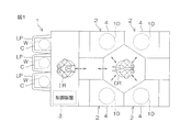
- FIG. 1 is a schematic view from above of a substrate processing apparatus according to an embodiment of the present invention.
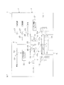
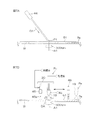
- FIG. 2 is a schematic view of the inside of a processing unit provided in the substrate processing apparatus as viewed in the horizontal direction.
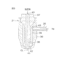
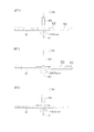
- FIG. 3 is a cross-sectional view for explaining the configuration of a droplet nozzle included in the processing unit.
- FIG. 4 is a block diagram for explaining the electrical configuration of the main part of the substrate processing apparatus.
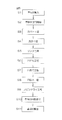
- FIG. 5 is a flowchart for explaining the contents of an example of substrate processing performed in the processing unit.
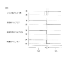
- FIG. 6 is a time chart for explaining the details of the cleaning step (S4 of FIG. 5) and the rinse step (S5 of FIG. 5) executed in the processing unit.
- FIG. 7A to 7B are schematic views showing the peripheral state of the substrate when the above-described example of substrate processing is being performed.
- 7C to 7D are schematic views showing the next process of FIG. 7B.
- 7E to 7G are schematic views showing the next step of FIG. 7D.
- 7H to 7J are schematic views showing the next process of FIG. 7G.
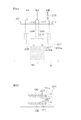
- FIG. 8A is a schematic cross-sectional view of a droplet nozzle.
- FIG. 8B is a schematic plan view of the droplet nozzle.
- FIG. 1 is a schematic view from above of a substrate processing apparatus according to an embodiment of the present invention.
- the substrate processing apparatus 1 is a single wafer processing apparatus that processes a substrate W such as a silicon wafer one by one.
- the substrate W is a disk-shaped substrate.
- the substrate processing apparatus 1 includes a plurality of processing units 2 that process a substrate W with a processing liquid and a rinse liquid, and a load port LP on which a carrier C that stores a plurality of substrates W processed by the processing unit 2 is placed.
- An indexer robot IR and a substrate transfer robot CR that transfer a substrate W between the load port LP and the processing unit 2 and a control device 3 that controls the substrate processing apparatus 1 are included.
- the indexer robot IR transfers the substrate W between the carrier C and the substrate transfer robot CR.
- the substrate transfer robot CR transfers the substrate W between the indexer robot IR and the processing unit 2.
- the plurality of processing units 2 have, for example, the same configuration.
- FIG. 2 is a schematic cross-sectional view for explaining a configuration example of the processing unit 2.
- the processing unit 2 holds a box-shaped chamber 4 and a single substrate W in a horizontal posture in the chamber 4 and spins the substrate W around a vertical rotation axis A1 passing through the center of the substrate W. (Substrate holding unit) 5; and a droplet supply unit 6 for supplying droplets of processing liquid (hereinafter sometimes referred to as processing liquid droplets) on the upper surface of the substrate W held by the spin chuck 5.
- the processing unit 2 further includes a gas supply unit 9 for spraying nitrogen gas (N 2 ) as an example of an inert gas as a gas onto the upper surface of the substrate W, and a cylindrical processing cup 10 surrounding the spin chuck 5.
- N 2 nitrogen gas
- the chamber 4 includes a box-shaped partition 12 accommodating the spin chuck 5 and the like.
- the spin chuck 5 As the spin chuck 5, a holding type chuck is adopted which holds the substrate W horizontally by holding the substrate W in the horizontal direction.
- the spin chuck 5 includes a spin motor (rotation unit) 15, a spin shaft 16 integrated with a drive shaft of the spin motor 15, and a disc attached substantially horizontally to the upper end of the spin shaft 16. And a spin base 17 of
- the spin base 17 includes a horizontal, circular upper surface 17 a having an outer diameter larger than the outer diameter of the substrate W.
- a plurality of (three or more, for example, six) sandwiching members 18 are disposed on the periphery of the upper surface 17a.
- the plurality of holding members 18 are arranged at equal intervals, for example, at appropriate intervals on the circumference corresponding to the outer peripheral shape of the substrate W at the upper surface peripheral portion of the spin base 17.
- the spin chuck 5 is not limited to the sandwich type, and for example, the substrate W is held in a horizontal posture by vacuum suction of the back surface of the substrate W, and further rotation around the vertical rotation axis in that state.
- a vacuum suction type vacuum chuck
- a vacuum suction type vacuum chuck
- rotates the substrate W held by the spin chuck 5 may be employed.
- the droplet supply unit 6 holds a droplet nozzle (multi-fluid nozzle) 19 that jets a processing liquid droplet toward the upper surface of the substrate W held by the spin chuck 5 and the droplet nozzle 19 at the tip.
- the nozzle arm 20 and a first nozzle moving unit (supply position moving unit) 21 for moving the droplet nozzle 19 by rotating the nozzle arm 20 are included.
- the first nozzle moving unit 21 swings the nozzle arm 20
- the droplet nozzle 19 swings horizontally along a locus passing through the central portion of the upper surface of the substrate W in plan view.
- the droplet nozzle 19 has a form of a multi-fluid nozzle (spray nozzle, more specifically, a two-fluid nozzle) that ejects a minute droplet of the processing liquid.
- the droplet nozzle 19 is connected to a fluid supply unit that supplies a processing liquid and a gas to the droplet nozzle 19.
- the fluid supply unit includes a processing liquid pipe 25 that supplies the liquid drop nozzle 19 with the processing liquid of the normal temperature liquid from the processing liquid supply source, and a gas pipe 26 that supplies the gas from the gas supply source to the liquid drop nozzle 19. Including.
- Examples of the processing liquid to be supplied to the droplet nozzle 19 include water and cleaning chemical solutions.
- Water is, for example, deionized water (DIW), but is not limited to DIW, and is any of carbonated water, electrolytic ion water, hydrogen water, ozone water, and hydrochloric acid water of dilute concentration (for example, about 10 ppm to 100 ppm).
- the cleaning solution may be, for example, an alkali solution such as SC1 (a solution containing NH 4 OH and H 2 O 2 ) or ammonia water (a solution containing NH 4 OH) or an acid solution.
- the treatment liquid pipe 25 is provided with a treatment liquid valve 27 that switches discharge and supply stop of the treatment liquid from the treatment liquid pipe 25 to the droplet nozzle 19.
- the gas pipe 26 is provided with a droplet gas valve 29 that switches discharge and supply of gas from the gas pipe 26 to the droplet nozzle 19.
- a nitrogen gas N 2
- inert gas other than nitrogen gas, for example, may be employed as dry air or clean air as an example.
- FIG. 3 is a cross-sectional view schematically showing the configuration of the droplet nozzle 19.
- the droplet nozzle 19 has a substantially cylindrical outer shape.
- the droplet nozzle 19 includes an outer cylinder 36 constituting a casing, and an inner cylinder 37 fitted inside the outer cylinder 36.
- the outer cylinder 36 and the inner cylinder 37 are coaxially disposed on the common central axis line CL and are connected to each other.
- the internal space of the inner cylinder 37 is a straight treatment liquid flow path 38 through which the treatment liquid from the treatment liquid pipe 25 flows.
- a cylindrical gas flow path 39 through which the gas supplied from the gas pipe 26 flows is formed.
- the treatment liquid flow path 38 is opened at the upper end of the inner cylinder 37 as the treatment liquid inlet 40.
- the processing liquid from the processing liquid pipe 25 is introduced into the processing liquid flow path 38 via the processing liquid inlet 40.
- the processing liquid flow path 38 is opened at the lower end of the inner cylinder 37 as a circular processing liquid discharge port 41 having a center on the central axis CL.
- the processing liquid introduced into the processing liquid flow path 38 is discharged from the processing liquid discharge port 41.
- the gas passage 39 is a cylindrical gap having a central axis common to the central axis CL, is closed by the upper end of the outer cylinder 36 and the inner cylinder 37, and the central axis at the lower end of the outer cylinder 36 and the inner cylinder 37.
- An annular gas discharge port 42 having a center on the CL and surrounding the processing liquid discharge port 41 is opened.
- the lower end portion of the gas flow passage 39 has a flow passage area smaller than that of the middle portion in the lengthwise direction of the gas flow passage 39, and the diameter is reduced toward the lower side.
- a gas inlet 43 communicating with the gas flow passage 39 is formed in the middle portion of the outer cylinder 36.
- the gas pipe 26 is connected to the gas introduction port 43 in a state of penetrating the outer cylinder 36, and the internal space of the gas pipe 26 and the gas flow path 39 are in communication.
- the gas from the gas pipe 26 is introduced into the gas flow path 39 via the gas inlet 43 and discharged from the gas discharge port 42.
- the processing liquid valve 27 By opening the processing liquid valve 27 and discharging the processing liquid from the processing liquid discharge port 41 while opening the droplet gas valve 29 and discharging the gas from the gas discharge port 42, the processing liquid in the vicinity of the droplet nozzle 19 By colliding (mixing) the gases with each other, minute droplets of the processing solution can be generated, and the processing solution can be discharged in the form of a spray.
- the treatment liquid ejection port 41 and the gas ejection port 42 form an ejection portion which ejects the treatment liquid droplets.
- the rinse liquid supply unit 7 includes a rinse liquid nozzle 44.
- the rinse liquid nozzle 44 is, for example, a straight nozzle that discharges the liquid in a continuous flow state, and is fixedly disposed above the spin chuck 5 with its discharge port directed toward the upper central portion of the substrate W.
- the rinse liquid nozzle 44 is an inclined nozzle that discharges the rinse liquid in a direction inclined in the vertical direction. That is, the incident direction D1 incident on the liquid landing position P1 is inclined with respect to the vertical direction.
- the inclination angle with respect to the vertical direction of the incident direction D1 is set to, for example, a predetermined angle within the range of 20 degrees to 30 degrees.
- the rinse liquid from the rinse liquid supply source is supplied to the rinse liquid nozzle 44 through the rinse liquid valve 45.
- the rinse liquid valve 45 When the rinse liquid valve 45 is opened, the continuous flow of rinse liquid supplied to the rinse liquid nozzle 44 is discharged from the discharge port set at the tip of the rinse liquid nozzle 44. In addition, when the rinse liquid valve 45 is closed, the discharge of the rinse liquid from the rinse liquid nozzle 44 is stopped.
- the rinse liquid discharged from the rinse liquid nozzle 44 is water. That is, the liquid type discharged from the rinse liquid nozzle 44 may be the same as or different from the processing liquid discharged from the droplet nozzle 19.
- the protective liquid supply unit 8 includes a protective liquid nozzle 46.
- the protective liquid nozzle 46 is, for example, a straight nozzle that discharges the liquid in a continuous flow state.
- the protective liquid nozzle 46 is a vertical nozzle that discharges the protective liquid downward in the vertical direction. That is, the protective liquid nozzle 46 has a discharge port 46 a directed vertically downward at the tip.
- the protective liquid from the protective liquid supply source is supplied to the protective liquid nozzle 46 through the protective liquid valve 47.
- the protective liquid valve 47 When the protective liquid valve 47 is opened, the continuous flow of protective liquid supplied to the protective liquid nozzle 46 is discharged from the discharge port 46 a of the protective liquid nozzle 46. Further, when the protective liquid valve 47 is closed, the discharge of the processing liquid from the protective liquid nozzle 46 is stopped.
- the protective liquid discharged from the protective liquid nozzle 46 is, for example, water.
- the protective liquid nozzle 46 is attached to the nozzle arm 20. That is, the protective liquid nozzle 46 is supported by the nozzle arm 20 common to the droplet nozzle 19.
- the protective liquid nozzle 46 is disposed inward of the droplet nozzle 19 in the radial direction of rotation of the substrate W.
- the droplet nozzle 19 and the protective liquid nozzle 46 swing horizontally along a locus passing through the upper surface central portion of the substrate W in plan view. In other words, it is provided so as to be movable along with the movement of the supply position (hereinafter referred to as “droplet supply position”) DA (see FIG.
- the droplet supply position DA can be covered by the protective liquid discharged from the protective liquid nozzle 46.
- the protective liquid nozzle 46 and the droplet nozzle 19 are disposed at substantially the same height.
- the gas supply unit 9 is connected to a gas nozzle 49 for discharging gas (N 2 ) downward, a second nozzle movement unit 50 for moving the gas nozzle 49, and the gas nozzle 49. And a gas valve 52 which is interposed in the gas pipe 51 and switches supply and stop of the organic solvent vapor from the gas pipe 51 to the gas nozzle 49. When the gas valve 52 is opened, the inert gas from the gas supply source is discharged downward from the discharge port 49 a of the gas nozzle 49.
- the processing cup 10 is disposed outward (in a direction away from the rotation axis A1) than the substrate W held by the spin chuck 5.
- the processing cup 10 surrounds the spin base 17.
- a liquid such as a processing liquid, a rinse liquid, or a protective liquid
- the liquid supplied to the substrate W is shaken off around the substrate W.
- the upper end 10 a of the processing cup 10 is disposed above the spin base 17. Therefore, the liquid discharged around the substrate W is received by the processing cup 10. Then, the liquid received by the processing cup 10 is sent to a recovery device or a waste liquid device (not shown).
- FIG. 4 is a block diagram for explaining the electrical configuration of the main part of the substrate processing apparatus 1.
- the control device 3 controls the operations of the spin motor 15, the first and second nozzle moving units 21, 50 and the like according to a predetermined program. Furthermore, the control device 3 controls the processing liquid valve 27, the droplet gas valve 29, the rinse liquid valve 45, the protective liquid valve 47, the gas valve 52, and the like.
- FIG. 5 is a flow chart for explaining the contents of an example of substrate processing performed in the processing unit.
- FIG. 6 is a time chart for explaining the details of the cleaning step (S4 in FIG. 5) and the rinse step (S5 in FIG. 5) executed in the processing unit 2.
- 7A to 7J are schematic views showing the peripheral state of the substrate W when the substrate processing example is being performed.
- FIGS. 7A to 7J Reference is made as appropriate to FIGS. 7A to 7J.
- the first example of substrate processing is cleaning processing for removing foreign matter (particles) from the surface of the substrate W exhibiting hydrophobicity.
- a surface of the substrate W exhibiting hydrophobicity titanium nitride, polysilicon, a low-k film, etc. can be exemplified.
- the unprocessed substrate W is carried from the carrier C to the processing unit 2 by the indexer robot IR and the substrate transport robot CR, and carried into the chamber 4 (S1 in FIG. 5: substrate W carried in), and the substrate W is on its surface (cleaning The substrate W is transferred to the spin chuck 5 with the target surface facing upward, and the substrate W is held by the spin chuck 5.
- the droplet nozzle 19, the protective liquid nozzle 46 and the gas nozzle 49 are retracted to the retracted position set to the side of the spin chuck 5.
- the control device 3 controls the spin motor 15 to start the rotation of the substrate W (step S2 in FIG. 5).
- the substrate W is raised to a predetermined liquid processing speed (in the range of about 50 rpm to about 1000 rpm, for example, about 500 rpm), and then maintained at that liquid processing speed.
- a predetermined liquid processing speed in the range of about 50 rpm to about 1000 rpm, for example, about 500 rpm
- the control device 3 executes a covering process (step S3 in FIG. 5).
- the cover step S3 is a step for forming a liquid film that protects the upper surface of the substrate W from the direct ejection of the treatment liquid droplets in the cleaning step S4 to be executed next.
- a liquid i.e., a rinse liquid
- a rinse liquid discharged from the rinse liquid nozzle 44 is used to form a liquid film.
- the control device 3 opens the rinse solution valve 45 and discharges the rinse solution from the rinse solution nozzle 44 toward the upper surface of the substrate W as shown in FIG. 7A.
- the discharge flow rate of the rinse liquid discharged from the rinse liquid nozzle 44 is a relatively large flow rate (for example, about 1000 (milliliter / minute)).
- the rinse liquid discharged from the rinse liquid nozzle 44 is deposited at the landing position P1.
- the upper surface of the substrate W flows toward the periphery.
- the incident direction D1 is inclined with respect to the vertical direction, it can be widely spread over the upper surface of the substrate W.
- the liquid film 61 covering the entire upper surface of the substrate W can be easily formed.
- the liquid film 61 functions as a protective film that protects the upper surface of the substrate W from direct ejection of the processing liquid droplets in the cleaning step S4 to be performed next.
- the control device 3 controls the first nozzle moving unit 21 to move the droplet nozzle 19 and the protective liquid nozzle 46 above the substrate W from the retracted position in the cover step S3.
- the droplet nozzle 19 and the protective liquid nozzle 46 are disposed at the peripheral position Pe.
- the peripheral position Pe is the position of the droplet nozzle 19 and the protective liquid nozzle 46 such that the droplet supply position DA from the droplet nozzle 19 is disposed in the peripheral region Re of the upper surface of the substrate W in plan view.
- the peripheral region Re of the upper surface of the substrate W refers to an annular region having a width of about 0.1 to 10 mm from the peripheral edge of the substrate W.
- the control device 3 closes the rinse liquid valve 45 and the supply of the rinse liquid to the upper surface of the substrate W is stopped. Be done. Thus, the cover process S3 is completed.
- the cleaning step S4 is a step of cleaning the top surface of the substrate W by supplying the processing liquid droplets from the droplet nozzle 19 to the top surface of the substrate W.
- the control device 3 opens the processing liquid valve 27 and the droplet gas valve 29.
- the treatment liquid droplets and nitrogen gas which is an example of a gas, are simultaneously supplied to the droplet nozzles 19, and the supplied treatment liquid droplets and nitrogen gas are discharged from the discharge port outside the droplet nozzles 19 (treatment liquid discharge It mixes near the exit 41 (refer FIG. 2).
- a jet of droplets of the processing liquid is formed, and the jet of droplets of the processing liquid is discharged from the droplet nozzle 19. Therefore, a circular droplet supply position DA is formed on the upper surface of the substrate W. Since a large number of process liquid droplets are sprayed from the droplet nozzle 19 to the droplet supply position DA, foreign matter (such as particles) adhering to the droplet supply position DA is physically detected by the collision of the process liquid droplets. Can be removed (physical cleaning).
- control device 3 opens the protective fluid valve 47 and discharges the protective fluid from the protective fluid nozzle 46. Since the protective liquid from the protective liquid nozzle 46 is incident on the upper surface of the substrate W from the vertical direction, the protective liquid can be favorably deposited on the upper surface of the substrate W.
- the liquid deposition position of the protective liquid from the protective liquid nozzle 46 is close to the droplet supply position DA, and therefore, the droplet supplied position DA is covered by the liquid-laminated protective liquid.
- the processing is continued while holding the liquid film 61 formed in the cover step S3 (that is, coverage). That is, in the state where the entire upper surface of the substrate W is covered with the liquid film, the processing liquid droplets are sprayed to the droplet supply position DA. Thereby, it is possible to suppress or prevent reattachment of foreign matter (particles and the like) to the substrate W.
- the discharge flow rate of the protective liquid from the protective liquid nozzle 46 is a small flow rate (for example, about 400 (milliliter / minute)). Therefore, the liquid film 61 does not become too thick at the droplet supply position DA. Therefore, the damage given to the upper surface of substrate W can be reduced more effectively by this, controlling or preventing generating of a splash.
- the protective liquid supplied in the cleaning step S4 can prevent the liquid on the upper surface of the substrate W from running out.
- the cleaning step S4 it is possible to keep the entire surface of the upper surface of the substrate W covered with the liquid film (coverage).
- the controller 3 controls the droplet nozzle 19 and the protective liquid nozzle 46 between the peripheral position Pe and the central position Pc by the first nozzle moving unit 21 while rotating the substrate W at the liquid processing speed.
- the central position Pc is the position of the droplet nozzle 19 and the protective liquid nozzle 46 such that the droplet supply position DA from the droplet nozzle 19 is disposed at the center of the upper surface of the substrate W.
- the cleaning step S4 is completed.
- the control device 3 continues the discharge of the treatment liquid droplets from the droplet nozzles 19, while maintaining the droplet nozzles 19 and the protective solution nozzle 46 at the central position Pc.
- the control device 3 closes the processing solution valve 27 and the droplet gas valve 29, as shown in FIG. 7D. The ejection of the processing liquid droplets from the droplet nozzles 19 is stopped.
- the cleaning step S4 is completed.
- a rinse step (step S5 in FIG. 5) of supplying a rinse liquid to the substrate W is performed.
- the control device 3 opens the rinse solution valve 45 and discharges the rinse solution in a continuous flow from the rinse solution nozzle 44 toward the central portion of the upper surface of the substrate W.
- the rinse liquid discharged from the rinse liquid nozzle 44 is deposited at the liquid deposition position P1 set at the central portion of the upper surface of the substrate W.
- the rinse liquid deposited at the liquid deposition position P1 receives centrifugal force due to the rotation of the substrate W, and flows toward the peripheral end of the substrate W on the upper surface of the substrate W.
- the control device 3 directs the droplet nozzle 19 and the protective solution nozzle 46 from the peripheral position Pe to the central position Pc while stopping the discharge of the treatment liquid droplet from the droplet nozzle 19. Move it.
- the droplet nozzle 19 and the protective liquid nozzle 46 which have reached the central position Pc are stopped at the central position Pc.
- a liquid film 61 is formed to cover the entire upper surface of the substrate W with a liquid film.
- a paddle step S6 of forming a paddle-like liquid film 62 on the upper surface of the substrate W is performed.
- the protective liquid is discharged from the protective liquid nozzle 46 disposed at the central position Pc.
- the control device 3 controls the spin motor 15 to gradually reduce the rotational speed of the substrate W from the liquid processing speed to the paddle speed (a low rotational speed of zero or about 40 rpm or less, for example, about 10 rpm). Thereafter, the rotational speed of the substrate W is maintained at the paddle speed (paddle process (step S6 in FIG. 5)). Thereby, as shown in FIG.
- the liquid film 62 covering the entire upper surface of the substrate W is supported in a paddle shape on the upper surface of the substrate W (a paddle-like liquid film 62 covering the entire upper surface of the substrate W is formed ).
- the centrifugal force acting on the paddle-like liquid film 62 is smaller than the surface tension acting between the liquid contained in the liquid film 62 and the upper surface of the substrate W, or the above-mentioned centrifugal force It almost antagonizes the surface tension. Due to the deceleration of the substrate W, the centrifugal force acting on the liquid on the substrate W is weakened, and the amount of liquid discharged from the substrate W is reduced.
- the control device 3 closes the protective liquid valve 47 and stops the discharge of the protective liquid from the protective liquid nozzle 46.
- the control device 3 closes the protective fluid valve 47 and stops the discharge of the protective fluid from the protective fluid nozzle 46.
- the control device 3 controls the first nozzle moving unit 21 to return the droplet nozzle 19 and the protective liquid nozzle 46 to the retracted position. Further, as shown in FIG. 7F, the control device 3 controls the second nozzle moving unit 50 to arrange the gas nozzle 49 in the information of the central portion of the upper surface of the substrate W.
- the control device 3 executes an exclusion step of excluding the paddle-like liquid film 62 from the upper surface of the substrate W.
- the removing step includes a drilling step (step S7 in FIG. 5) and a hole enlarging step (step S8 in FIG. 5).
- the drilling process S7 is performed, and after the drilling process S7 ends, the hole enlarging process S8 is performed.
- a circular hole (i.e., a dried area) 63 from which the liquid is removed is formed in the central portion of the paddle-like liquid film 62.
- the control device 3 opens the gas valve 52 and discharges the inert gas downward from the gas nozzle 49 toward the upper central portion of the substrate W.
- the liquid at the center of the paddle-like liquid film 62 is blown away and removed by the inert gas blowing pressure (gas pressure).
- a hole 63 is formed at the center of the upper surface of the substrate W.
- a hole enlarging step S8 is performed.
- the control device 3 controls the spin motor 15 to increase the rotational speed of the substrate W to a predetermined drilling speed (for example, 200 rpm).
- a predetermined drilling speed for example, 200 rpm.
- the hole 63 starts to expand as shown in FIG. 7H.
- the control device 3 gradually increases the rotational speed of the substrate W further to 2400 rpm.
- FIG. 7I the hole 63 is further enlarged, and eventually, as shown in FIG. 7J. , And the hole 63 is enlarged over the entire area of the substrate W. As a result, all the paddle-like liquid films 62 are discharged out of the substrate W.
- the paddle-like liquid film 62 maintains the state of liquid mass throughout the period of expansion of the hole 63. That is, the paddle-like liquid film 62 can be removed from above the substrate W without the liquid after the liquid mass division remaining on the upper surface of the substrate W.
- the fact that the liquid mass of the liquid film 62 does not break up in the process of expanding the hole 63 is due to the fact that the paddle-like liquid film 62 is thick. That is, division of the liquid mass of the liquid film 62 in the hole expansion step S8 is prevented by executing the exclusion step after the paddle step S6.
- the control device 3 ends the hole expansion step S8. Specifically, the control device 3 closes the gas valve 52 to stop the discharge of the inert gas from the gas nozzle 49.
- the control device 3 executes a spin dry step (step S9 in FIG. 5). Specifically, the controller 3 further accelerates the substrate W to a spin dry speed (for example, about 2400 rpm). Thereby, the water on the upper surface of the substrate is shaken off.
- a spin dry speed for example, about 2400 rpm
- the control device 3 controls the spin motor 15 to stop the rotation of the spin chuck 5 (that is, the rotation of the substrate W) (step S10 in FIG. 5). Thereafter, the substrate transport robot CR enters the processing unit 2 and carries out the processed substrate W out of the processing unit 2 (step S11 in FIG. 5).
- the substrate W is transferred from the substrate transfer robot CR to the indexer robot IR, and is stored in the carrier C by the indexer robot IR.
- the droplet supply position on the upper surface of the substrate W is for spraying the processing liquid droplets.
- the thickness of the liquid film 61 is locally reduced, and if mist adheres to the droplet supply position DA, there is a possibility that a water mark may be generated or particles may be generated.
- the cause of mist generation is splashing, it has been desired to suppress or prevent the adhesion of the mist to the droplet supply position DA by suppressing or preventing the splashing.
- the rinse liquid is supplied to the droplet supply position DA prior to the stop of the discharge of the processing liquid droplets. There is a risk of reaching. In this case, as processing liquid droplets are sprayed to the thick liquid film as the rinse liquid is supplied, liquid splash may occur.
- the processing liquid from the droplet nozzle 19 at the timing before the rinse liquid is discharged from the rinse liquid nozzle 44 or at the same time as the rinse liquid is discharged from the rinse liquid nozzle 44 Since the discharge of the droplets is stopped, it is possible to avoid the discharge of the treatment liquid droplets to the thick liquid film. Thereby, it is possible to suppress or prevent the occurrence of liquid splashing in the transition from the cleaning step S4 to the rinsing step S5. Therefore, it is possible to suppress or prevent the mist caused by the splashing from adhering to the droplet supply position DA on the upper surface of the substrate W. Therefore, it is possible to suppress or prevent the mist from adhering to the droplet supply position DA on the upper surface of the substrate W. Thereby, even when the upper surface of the substrate W exhibits hydrophobicity, the generation of the watermark on the upper surface (surface) of the substrate W can be suppressed or prevented.
- the processing liquid from the droplet nozzle 19 is stopped by stopping both the supply of the processing liquid to the droplet nozzle 19 and the supply of the gas to the droplet nozzle 19. It has been described that the discharge of droplets is stopped. However, in order to stop the discharge of the processing liquid droplet from the droplet nozzle 19, only the supply of the gas to the droplet nozzle 19 may be stopped. In this case, the discharge of the continuous flow of the processing liquid from the droplet nozzle 19 is continued.
- the rinse step S5 is inhibited. It does not become. Rather, from the viewpoint of covering the upper surface of the substrate W, it is preferable to discharge the processing liquid in a continuous flow form from the droplet nozzle 19 even after the discharge of droplets of the processing liquid from the droplet nozzle 19 is stopped.
- the discharge of the treatment liquid droplets may be stopped (that is, the rinse liquid discharge from the rinse liquid nozzle 44 may be started before the discharge liquid treatment from the droplet nozzles 19 is stopped).
- the liquid of the substrate W is therefore The processing time required for the rinse liquid supplied to the central portion of the substrate W to reach the peripheral region Re of the substrate W is measured in advance, and discharge of the rinse liquid from the rinse liquid nozzle 44 is started, It is also possible to stop the discharge of the processing liquid droplets from the droplet nozzles 19 in less than the required arrival period. In this case, since the discharge of the processing liquid droplets is stopped at the timing before the rinse liquid reaches the droplet supply position, it is possible to prevent the processing liquid droplets from being discharged to the thick liquid film. .
- the paddle-like liquid film 62 is formed using the protective liquid from the protective liquid nozzle 46 in the paddle step S6, but in addition to the protective liquid from the protective liquid nozzle 46
- the paddle-like liquid film 62 may be formed by the continuous flow of the processing solution from the droplet nozzle 19.
- the paddle-like liquid film 62 may be formed by the continuous flow of the processing liquid from the droplet nozzle 19 without supplying the protective liquid from the protective liquid nozzle 46.
- the paddle-like liquid film 62 is formed using the protective liquid from the protective liquid nozzle 46 in the paddle process S6, the liquid provided separately from the protective liquid nozzle 46
- the paddle-like liquid film 62 may be formed by discharging the liquid (for example, water) from the filling nozzle.
- the liquid deposition nozzle is a vertical nozzle that discharges liquid downward. Since the liquid from the nozzle is vertically incident on the upper surface of the substrate, the liquid can be favorably deposited on the upper surface of the substrate, whereby the paddle-like liquid film 62 can be easily formed. it can.
- the liquid film 61 is formed using the rinse liquid from the rinse liquid nozzle 44 in the cover step S3, the cover nozzle provided separately from the rinse liquid nozzle 44
- the liquid film 61 may be formed by discharging liquid (for example, water) from the above.
- the droplet supply position DA is moved between the central portion of the upper surface of the substrate W and the peripheral end of the upper surface of the substrate W (half scan). It may be moved between one peripheral end of the upper surface and the other peripheral end opposite to the one peripheral end and the center of the upper surface (full scan).
- the movement of the droplet supply position DA may not be reciprocating movement, but may be one-way movement moving from the center of the upper surface of the substrate W toward the peripheral region Re of the upper surface of the substrate W.
- the droplet nozzle 19 has been described as a two-fluid nozzle that mixes one type of liquid and one type of gas, but in addition to this, another type of fluid (gas and (Or liquid) can also be used as a nozzle capable of mixing. That is, the droplet nozzle (multiple fluid nozzle) may mix three or more fluids.
- FIG. 8A is a schematic cross-sectional view of the droplet nozzle 201.
- FIG. 8B is a schematic plan view of the droplet nozzle 201.
- the droplet nozzle 201 is connected to a treatment liquid pipe 210 for supplying the treatment liquid from the treatment liquid supply source to the droplet nozzle 201.
- a treatment liquid is constantly supplied to the droplet nozzle 201 by pressure-feed by a pump.
- the droplet nozzle 201 is connected to a drainage pipe 214 in which a discharge valve 215 is interposed.
- the droplet nozzle 201 includes a piezoelectric element 216 disposed inside the droplet nozzle 201.
- the piezoelectric element 216 is connected to a voltage application unit 218 such as an inverter via a wire 217.
- the voltage application unit 218 includes, for example.
- the piezoelectric element 216 vibrates at a frequency corresponding to the frequency of the applied alternating voltage.
- the frequency of vibration of the piezoelectric element 216 can be changed by changing the frequency of the AC voltage applied to the piezoelectric element 216 to an arbitrary frequency (for example, several hundred KHz to several MHz).
- the droplet nozzle 201 includes a main body 221. As shown in FIG. 8A, the main body 221 connects the supply port 224 to which the processing liquid is supplied, the discharge port 225 to discharge the processing liquid supplied to the supply port 224, and the supply port 224 and the discharge port 225. A treatment liquid flow passage 226 and a plurality of injection ports 227 connected to the treatment liquid flow passage 226 are included. The treatment liquid flow passage 226 is provided inside the main body 221.
- the supply port 224, the exhaust port 225, and the injection port 227 are open at the surface of the main body 221.
- the supply port 224 and the discharge port 225 are located above the injection port 227.
- the lower surface 201 a of the main body 221 is, for example, a horizontal flat surface, and the injection port 227 is opened at the lower surface 201 a of the main body 221.
- the injection port 227 is, for example, a fine hole having a diameter of several ⁇ m to several tens of ⁇ m.
- the treatment liquid piping 210 and the drainage piping 214 are connected to the supply port 224 and the discharge port 225, respectively.
- the plurality of injection ports 227 form a plurality of (for example, four in FIG. 8B) rows L.
- Each row L is constituted by a large number (for example, 10 or more) of injection ports 227 arranged at equal intervals.
- Each row L extends linearly along the horizontal longitudinal direction.
- Each row L is not limited to a linear shape, and may be a curved shape.
- the processing liquid supplied to the supply port 224 via the processing liquid pipe 210 is supplied to the processing liquid flow passage 226.
- the pressure (liquid pressure) of the processing liquid in the processing liquid flow passage 226 is high. Therefore, in the state where the discharge valve 215 is closed, the treatment liquid is injected from each injection port 227 by the fluid pressure. Furthermore, when the AC voltage is applied to the piezoelectric element 216 in the state where the discharge valve 215 is closed, the vibration of the piezoelectric element 216 is applied to the processing liquid flowing through the processing liquid flow passage 226 and The treatment liquid is separated by this vibration.
- the processing liquid supplied to the processing liquid flow passage 226 is discharged from the discharge port 225 to the drain piping 214. That is, in the state where the discharge valve 215 is opened, the hydraulic pressure in the treatment liquid flow passage 226 is not sufficiently increased, and therefore the treatment liquid supplied to the treatment liquid flow passage 226 is an injection port which is a fine hole.
- the gas is discharged from the discharge port 225 to the drainage pipe 214 without being injected from the nozzle 227. Therefore, the discharge of the processing liquid from the injection port 227 is controlled by opening and closing the discharge valve 215.
- the control device 3 opens the discharge valve 215 while the droplet nozzle 201 is not used for processing the substrate W (during standby of the droplet nozzle 201). Therefore, even while the droplet nozzle 201 is on standby, the state in which the processing liquid is flowing inside the droplet nozzle 201 is maintained.
- the substrate processing apparatus is a substrate for liquid crystal display device, organic EL (electroluminescence) display.
- Devices for processing substrates such as FPD (Flat Panel Display) substrates for optical devices, substrates for optical disks, substrates for magnetic disks, substrates for magneto-optical disks, substrates for photomasks, ceramic substrates, substrates for solar cells, etc. Good.
- FPD Full Panel Display
- the effect of the present invention is particularly remarkable when the surface of the substrate W exhibits hydrophobicity.
- Substrate processing apparatus 3 Controller 4: Chamber 5: Spin chuck (substrate holding unit) 6: Droplet supply unit 7: Rinsing liquid supply unit 8: Protective liquid supply unit 15: Spin motor (rotating unit) 19: Droplet nozzle (multiple fluid nozzle) 21: First nozzle moving unit (supply position moving unit) 44: rinse liquid nozzle 46: protective liquid nozzle 201: droplet nozzle DA: droplet supply position P1: liquid contact position W: substrate
Landscapes
- Engineering & Computer Science (AREA)
- Physics & Mathematics (AREA)
- Condensed Matter Physics & Semiconductors (AREA)
- General Physics & Mathematics (AREA)
- Manufacturing & Machinery (AREA)
- Computer Hardware Design (AREA)
- Microelectronics & Electronic Packaging (AREA)
- Power Engineering (AREA)
- Cleaning Or Drying Semiconductors (AREA)
Priority Applications (2)
| Application Number | Priority Date | Filing Date | Title |
|---|---|---|---|
| CN201880060333.XA CN111095494B (zh) | 2017-10-12 | 2018-10-04 | 基板处理方法及基板处理装置 |
| KR1020207008765A KR102346493B1 (ko) | 2017-10-12 | 2018-10-04 | 기판 처리 방법 및 기판 처리 장치 |
Applications Claiming Priority (2)
| Application Number | Priority Date | Filing Date | Title |
|---|---|---|---|
| JP2017198618A JP6966917B2 (ja) | 2017-10-12 | 2017-10-12 | 基板処理方法および基板処理装置 |
| JP2017-198618 | 2017-10-12 |
Publications (1)
| Publication Number | Publication Date |
|---|---|
| WO2019073905A1 true WO2019073905A1 (ja) | 2019-04-18 |
Family
ID=66100772
Family Applications (1)
| Application Number | Title | Priority Date | Filing Date |
|---|---|---|---|
| PCT/JP2018/037271 Ceased WO2019073905A1 (ja) | 2017-10-12 | 2018-10-04 | 基板処理方法および基板処理装置 |
Country Status (5)
| Country | Link |
|---|---|
| JP (1) | JP6966917B2 (enExample) |
| KR (1) | KR102346493B1 (enExample) |
| CN (1) | CN111095494B (enExample) |
| TW (1) | TWI697948B (enExample) |
| WO (1) | WO2019073905A1 (enExample) |
Cited By (3)
| Publication number | Priority date | Publication date | Assignee | Title |
|---|---|---|---|---|
| CN114888722A (zh) * | 2022-05-17 | 2022-08-12 | 华海清科股份有限公司 | 一种化学机械抛光方法 |
| CN116153775A (zh) * | 2020-03-05 | 2023-05-23 | 东京毅力科创株式会社 | 基片处理方法和基片处理装置 |
| EP4434642A1 (en) * | 2023-03-22 | 2024-09-25 | Yield Engineering Systems, Inc. | Apparatus and method for coating removal |
Families Citing this family (2)
| Publication number | Priority date | Publication date | Assignee | Title |
|---|---|---|---|---|
| JP7285166B2 (ja) * | 2019-08-20 | 2023-06-01 | 株式会社荏原製作所 | 基板洗浄方法および基板洗浄装置 |
| KR102682854B1 (ko) * | 2020-06-02 | 2024-07-10 | 세메스 주식회사 | 기판 처리 방법 및 기판 처리 장치 |
Citations (3)
| Publication number | Priority date | Publication date | Assignee | Title |
|---|---|---|---|---|
| JP2003203892A (ja) * | 2001-11-01 | 2003-07-18 | Tokyo Electron Ltd | 基板洗浄装置及び基板洗浄方法 |
| JP2007012998A (ja) * | 2005-07-01 | 2007-01-18 | Dainippon Screen Mfg Co Ltd | 基板洗浄装置およびそれを備えた基板処理システム |
| JP2016167582A (ja) * | 2015-03-05 | 2016-09-15 | 株式会社Screenホールディングス | 基板処理方法および基板処理装置 |
Family Cites Families (6)
| Publication number | Priority date | Publication date | Assignee | Title |
|---|---|---|---|---|
| TW561516B (en) * | 2001-11-01 | 2003-11-11 | Tokyo Electron Ltd | Substrate processing apparatus and substrate processing method |
| US7766565B2 (en) * | 2005-07-01 | 2010-08-03 | Sokudo Co., Ltd. | Substrate drying apparatus, substrate cleaning apparatus and substrate processing system |
| JP2008130643A (ja) * | 2006-11-17 | 2008-06-05 | Dainippon Screen Mfg Co Ltd | ノズル、基板処理装置および基板処理方法 |
| JP5151629B2 (ja) * | 2008-04-03 | 2013-02-27 | 東京エレクトロン株式会社 | 基板洗浄方法、基板洗浄装置、現像方法、現像装置及び記憶媒体 |
| JP5512424B2 (ja) * | 2010-07-06 | 2014-06-04 | 東京エレクトロン株式会社 | 基板洗浄装置および基板洗浄方法 |
| JP6508721B2 (ja) | 2015-09-28 | 2019-05-08 | 株式会社Screenホールディングス | 基板処理方法および基板処理装置 |
-
2017
- 2017-10-12 JP JP2017198618A patent/JP6966917B2/ja active Active
-
2018
- 2018-10-04 CN CN201880060333.XA patent/CN111095494B/zh active Active
- 2018-10-04 KR KR1020207008765A patent/KR102346493B1/ko active Active
- 2018-10-04 WO PCT/JP2018/037271 patent/WO2019073905A1/ja not_active Ceased
- 2018-10-12 TW TW107136001A patent/TWI697948B/zh active
Patent Citations (3)
| Publication number | Priority date | Publication date | Assignee | Title |
|---|---|---|---|---|
| JP2003203892A (ja) * | 2001-11-01 | 2003-07-18 | Tokyo Electron Ltd | 基板洗浄装置及び基板洗浄方法 |
| JP2007012998A (ja) * | 2005-07-01 | 2007-01-18 | Dainippon Screen Mfg Co Ltd | 基板洗浄装置およびそれを備えた基板処理システム |
| JP2016167582A (ja) * | 2015-03-05 | 2016-09-15 | 株式会社Screenホールディングス | 基板処理方法および基板処理装置 |
Cited By (8)
| Publication number | Priority date | Publication date | Assignee | Title |
|---|---|---|---|---|
| CN116153775A (zh) * | 2020-03-05 | 2023-05-23 | 东京毅力科创株式会社 | 基片处理方法和基片处理装置 |
| KR20230105000A (ko) * | 2020-03-05 | 2023-07-11 | 도쿄엘렉트론가부시키가이샤 | 기판 처리 방법 및 기판 처리 장치 |
| KR102808108B1 (ko) * | 2020-03-05 | 2025-05-16 | 도쿄엘렉트론가부시키가이샤 | 기판 처리 방법 및 기판 처리 장치 |
| CN116153775B (zh) * | 2020-03-05 | 2025-11-18 | 东京毅力科创株式会社 | 基片处理方法和基片处理装置 |
| CN114888722A (zh) * | 2022-05-17 | 2022-08-12 | 华海清科股份有限公司 | 一种化学机械抛光方法 |
| EP4434642A1 (en) * | 2023-03-22 | 2024-09-25 | Yield Engineering Systems, Inc. | Apparatus and method for coating removal |
| US20250025987A1 (en) * | 2023-03-22 | 2025-01-23 | Yield Engineering Systems, Inc. | Apparatus for coating removal |
| US12330268B2 (en) * | 2023-03-22 | 2025-06-17 | Yield Engineering Systems, Inc. | Apparatus for coating removal |
Also Published As
| Publication number | Publication date |
|---|---|
| JP2019075413A (ja) | 2019-05-16 |
| CN111095494B (zh) | 2024-11-26 |
| TW201923876A (zh) | 2019-06-16 |
| TWI697948B (zh) | 2020-07-01 |
| KR20200041990A (ko) | 2020-04-22 |
| JP6966917B2 (ja) | 2021-11-17 |
| CN111095494A (zh) | 2020-05-01 |
| KR102346493B1 (ko) | 2021-12-31 |
Similar Documents
| Publication | Publication Date | Title |
|---|---|---|
| JP5852898B2 (ja) | 基板処理装置および基板処理方法 | |
| JP6521242B2 (ja) | 基板処理方法および基板処理装置 | |
| TWI620238B (zh) | Substrate processing method and substrate processing device | |
| TWI581867B (zh) | 基板處理裝置、基板處理方法、及噴嘴 | |
| TWI557792B (zh) | 基板處理裝置、基板處理方法及記憶媒體 | |
| CN111095494B (zh) | 基板处理方法及基板处理装置 | |
| KR20150005871A (ko) | 기판처리장치 및 기판처리방법 | |
| KR20140113511A (ko) | 기판 처리 장치 및 기판 처리 방법 | |
| TWI687971B (zh) | 基板處理裝置及基板處理方法 | |
| KR101975143B1 (ko) | 기판 처리 방법 및 기판 처리 장치 | |
| JP2016167582A (ja) | 基板処理方法および基板処理装置 | |
| JP2013065795A (ja) | 基板処理方法 | |
| JP6103429B2 (ja) | 基板処理装置および基板処理方法 | |
| JP5837788B2 (ja) | ノズル、基板処理装置、および基板処理方法 | |
| JP5785462B2 (ja) | 基板処理装置および基板処理方法 | |
| TWI834178B (zh) | 基板處理方法以及基板處理裝置 | |
| TW201803650A (zh) | 基板處理裝置及基板處理方法 | |
| JP6517113B2 (ja) | 基板処理装置および吐出ヘッド | |
| JP7777672B2 (ja) | 電子部品洗浄方法 | |
| KR102796895B1 (ko) | 전자 부품 세정 장치 |
Legal Events
| Date | Code | Title | Description |
|---|---|---|---|
| 121 | Ep: the epo has been informed by wipo that ep was designated in this application |
Ref document number: 18867202 Country of ref document: EP Kind code of ref document: A1 |
|
| ENP | Entry into the national phase |
Ref document number: 20207008765 Country of ref document: KR Kind code of ref document: A |
|
| NENP | Non-entry into the national phase |
Ref country code: DE |
|
| 122 | Ep: pct application non-entry in european phase |
Ref document number: 18867202 Country of ref document: EP Kind code of ref document: A1 |