WO2019073694A1 - 車両用熱交換器のシャッター構造 - Google Patents
車両用熱交換器のシャッター構造 Download PDFInfo
- Publication number
- WO2019073694A1 WO2019073694A1 PCT/JP2018/030828 JP2018030828W WO2019073694A1 WO 2019073694 A1 WO2019073694 A1 WO 2019073694A1 JP 2018030828 W JP2018030828 W JP 2018030828W WO 2019073694 A1 WO2019073694 A1 WO 2019073694A1
- Authority
- WO
- WIPO (PCT)
- Prior art keywords
- heat exchanger
- vehicle
- screen
- opening
- heat exchangers
- Prior art date
Links
Images
Classifications
-
- F—MECHANICAL ENGINEERING; LIGHTING; HEATING; WEAPONS; BLASTING
- F28—HEAT EXCHANGE IN GENERAL
- F28F—DETAILS OF HEAT-EXCHANGE AND HEAT-TRANSFER APPARATUS, OF GENERAL APPLICATION
- F28F13/00—Arrangements for modifying heat-transfer, e.g. increasing, decreasing
- F28F13/06—Arrangements for modifying heat-transfer, e.g. increasing, decreasing by affecting the pattern of flow of the heat-exchange media
-
- B—PERFORMING OPERATIONS; TRANSPORTING
- B60—VEHICLES IN GENERAL
- B60K—ARRANGEMENT OR MOUNTING OF PROPULSION UNITS OR OF TRANSMISSIONS IN VEHICLES; ARRANGEMENT OR MOUNTING OF PLURAL DIVERSE PRIME-MOVERS IN VEHICLES; AUXILIARY DRIVES FOR VEHICLES; INSTRUMENTATION OR DASHBOARDS FOR VEHICLES; ARRANGEMENTS IN CONNECTION WITH COOLING, AIR INTAKE, GAS EXHAUST OR FUEL SUPPLY OF PROPULSION UNITS IN VEHICLES
- B60K11/00—Arrangement in connection with cooling of propulsion units
- B60K11/08—Air inlets for cooling; Shutters or blinds therefor
-
- B—PERFORMING OPERATIONS; TRANSPORTING
- B60—VEHICLES IN GENERAL
- B60H—ARRANGEMENTS OF HEATING, COOLING, VENTILATING OR OTHER AIR-TREATING DEVICES SPECIALLY ADAPTED FOR PASSENGER OR GOODS SPACES OF VEHICLES
- B60H1/00—Heating, cooling or ventilating [HVAC] devices
- B60H1/32—Cooling devices
-
- B—PERFORMING OPERATIONS; TRANSPORTING
- B60—VEHICLES IN GENERAL
- B60K—ARRANGEMENT OR MOUNTING OF PROPULSION UNITS OR OF TRANSMISSIONS IN VEHICLES; ARRANGEMENT OR MOUNTING OF PLURAL DIVERSE PRIME-MOVERS IN VEHICLES; AUXILIARY DRIVES FOR VEHICLES; INSTRUMENTATION OR DASHBOARDS FOR VEHICLES; ARRANGEMENTS IN CONNECTION WITH COOLING, AIR INTAKE, GAS EXHAUST OR FUEL SUPPLY OF PROPULSION UNITS IN VEHICLES
- B60K11/00—Arrangement in connection with cooling of propulsion units
- B60K11/08—Air inlets for cooling; Shutters or blinds therefor
- B60K11/085—Air inlets for cooling; Shutters or blinds therefor with adjustable shutters or blinds
-
- F—MECHANICAL ENGINEERING; LIGHTING; HEATING; WEAPONS; BLASTING
- F01—MACHINES OR ENGINES IN GENERAL; ENGINE PLANTS IN GENERAL; STEAM ENGINES
- F01P—COOLING OF MACHINES OR ENGINES IN GENERAL; COOLING OF INTERNAL-COMBUSTION ENGINES
- F01P7/00—Controlling of coolant flow
- F01P7/02—Controlling of coolant flow the coolant being cooling-air
- F01P7/10—Controlling of coolant flow the coolant being cooling-air by throttling amount of air flowing through liquid-to-air heat exchangers
- F01P7/12—Controlling of coolant flow the coolant being cooling-air by throttling amount of air flowing through liquid-to-air heat exchangers by thermostatic control
-
- F—MECHANICAL ENGINEERING; LIGHTING; HEATING; WEAPONS; BLASTING
- F28—HEAT EXCHANGE IN GENERAL
- F28D—HEAT-EXCHANGE APPARATUS, NOT PROVIDED FOR IN ANOTHER SUBCLASS, IN WHICH THE HEAT-EXCHANGE MEDIA DO NOT COME INTO DIRECT CONTACT
- F28D1/00—Heat-exchange apparatus having stationary conduit assemblies for one heat-exchange medium only, the media being in contact with different sides of the conduit wall, in which the other heat-exchange medium is a large body of fluid, e.g. domestic or motor car radiators
- F28D1/02—Heat-exchange apparatus having stationary conduit assemblies for one heat-exchange medium only, the media being in contact with different sides of the conduit wall, in which the other heat-exchange medium is a large body of fluid, e.g. domestic or motor car radiators with heat-exchange conduits immersed in the body of fluid
- F28D1/0233—Heat-exchange apparatus having stationary conduit assemblies for one heat-exchange medium only, the media being in contact with different sides of the conduit wall, in which the other heat-exchange medium is a large body of fluid, e.g. domestic or motor car radiators with heat-exchange conduits immersed in the body of fluid with air flow channels
- F28D1/024—Heat-exchange apparatus having stationary conduit assemblies for one heat-exchange medium only, the media being in contact with different sides of the conduit wall, in which the other heat-exchange medium is a large body of fluid, e.g. domestic or motor car radiators with heat-exchange conduits immersed in the body of fluid with air flow channels with an air driving element
-
- B—PERFORMING OPERATIONS; TRANSPORTING
- B60—VEHICLES IN GENERAL
- B60K—ARRANGEMENT OR MOUNTING OF PROPULSION UNITS OR OF TRANSMISSIONS IN VEHICLES; ARRANGEMENT OR MOUNTING OF PLURAL DIVERSE PRIME-MOVERS IN VEHICLES; AUXILIARY DRIVES FOR VEHICLES; INSTRUMENTATION OR DASHBOARDS FOR VEHICLES; ARRANGEMENTS IN CONNECTION WITH COOLING, AIR INTAKE, GAS EXHAUST OR FUEL SUPPLY OF PROPULSION UNITS IN VEHICLES
- B60K11/00—Arrangement in connection with cooling of propulsion units
- B60K11/02—Arrangement in connection with cooling of propulsion units with liquid cooling
- B60K11/04—Arrangement or mounting of radiators, radiator shutters, or radiator blinds
-
- B—PERFORMING OPERATIONS; TRANSPORTING
- B60—VEHICLES IN GENERAL
- B60K—ARRANGEMENT OR MOUNTING OF PROPULSION UNITS OR OF TRANSMISSIONS IN VEHICLES; ARRANGEMENT OR MOUNTING OF PLURAL DIVERSE PRIME-MOVERS IN VEHICLES; AUXILIARY DRIVES FOR VEHICLES; INSTRUMENTATION OR DASHBOARDS FOR VEHICLES; ARRANGEMENTS IN CONNECTION WITH COOLING, AIR INTAKE, GAS EXHAUST OR FUEL SUPPLY OF PROPULSION UNITS IN VEHICLES
- B60K6/00—Arrangement or mounting of plural diverse prime-movers for mutual or common propulsion, e.g. hybrid propulsion systems comprising electric motors and internal combustion engines ; Control systems therefor, i.e. systems controlling two or more prime movers, or controlling one of these prime movers and any of the transmission, drive or drive units Informative references: mechanical gearings with secondary electric drive F16H3/72; arrangements for handling mechanical energy structurally associated with the dynamo-electric machine H02K7/00; machines comprising structurally interrelated motor and generator parts H02K51/00; dynamo-electric machines not otherwise provided for in H02K see H02K99/00
- B60K6/20—Arrangement or mounting of plural diverse prime-movers for mutual or common propulsion, e.g. hybrid propulsion systems comprising electric motors and internal combustion engines ; Control systems therefor, i.e. systems controlling two or more prime movers, or controlling one of these prime movers and any of the transmission, drive or drive units Informative references: mechanical gearings with secondary electric drive F16H3/72; arrangements for handling mechanical energy structurally associated with the dynamo-electric machine H02K7/00; machines comprising structurally interrelated motor and generator parts H02K51/00; dynamo-electric machines not otherwise provided for in H02K see H02K99/00 the prime-movers consisting of electric motors and internal combustion engines, e.g. HEVs
- B60K6/22—Arrangement or mounting of plural diverse prime-movers for mutual or common propulsion, e.g. hybrid propulsion systems comprising electric motors and internal combustion engines ; Control systems therefor, i.e. systems controlling two or more prime movers, or controlling one of these prime movers and any of the transmission, drive or drive units Informative references: mechanical gearings with secondary electric drive F16H3/72; arrangements for handling mechanical energy structurally associated with the dynamo-electric machine H02K7/00; machines comprising structurally interrelated motor and generator parts H02K51/00; dynamo-electric machines not otherwise provided for in H02K see H02K99/00 the prime-movers consisting of electric motors and internal combustion engines, e.g. HEVs characterised by apparatus, components or means specially adapted for HEVs
-
- B—PERFORMING OPERATIONS; TRANSPORTING
- B60—VEHICLES IN GENERAL
- B60Y—INDEXING SCHEME RELATING TO ASPECTS CROSS-CUTTING VEHICLE TECHNOLOGY
- B60Y2200/00—Type of vehicle
- B60Y2200/90—Vehicles comprising electric prime movers
- B60Y2200/92—Hybrid vehicles
-
- B—PERFORMING OPERATIONS; TRANSPORTING
- B60—VEHICLES IN GENERAL
- B60Y—INDEXING SCHEME RELATING TO ASPECTS CROSS-CUTTING VEHICLE TECHNOLOGY
- B60Y2306/00—Other features of vehicle sub-units
- B60Y2306/05—Cooling
-
- F—MECHANICAL ENGINEERING; LIGHTING; HEATING; WEAPONS; BLASTING
- F28—HEAT EXCHANGE IN GENERAL
- F28F—DETAILS OF HEAT-EXCHANGE AND HEAT-TRANSFER APPARATUS, OF GENERAL APPLICATION
- F28F2265/00—Safety or protection arrangements; Arrangements for preventing malfunction
- F28F2265/02—Safety or protection arrangements; Arrangements for preventing malfunction in the form of screens or covers
-
- Y—GENERAL TAGGING OF NEW TECHNOLOGICAL DEVELOPMENTS; GENERAL TAGGING OF CROSS-SECTIONAL TECHNOLOGIES SPANNING OVER SEVERAL SECTIONS OF THE IPC; TECHNICAL SUBJECTS COVERED BY FORMER USPC CROSS-REFERENCE ART COLLECTIONS [XRACs] AND DIGESTS
- Y02—TECHNOLOGIES OR APPLICATIONS FOR MITIGATION OR ADAPTATION AGAINST CLIMATE CHANGE
- Y02T—CLIMATE CHANGE MITIGATION TECHNOLOGIES RELATED TO TRANSPORTATION
- Y02T10/00—Road transport of goods or passengers
- Y02T10/80—Technologies aiming to reduce greenhouse gasses emissions common to all road transportation technologies
- Y02T10/88—Optimized components or subsystems, e.g. lighting, actively controlled glasses
Definitions
- the present disclosure relates to a shutter structure of a heat exchanger for a vehicle.
- Patent Document 1 proposes a grille shutter in which a plurality of blades arranged in parallel are opened and closed by a motor.
- a plurality of cooling water circuits may be provided, and two radiators may be stacked in the vertical direction and arranged in two stages.
- the shutter of Patent Document 1 is used for the radiator having such a configuration, it is not possible to cool only a part of the radiators stacked.
- a plurality of motors for opening and closing the blades are required.
- An object of the present disclosure is to provide a shutter structure capable of cooling only a necessary portion of a vehicle heat exchanger with a simple configuration.
- the shutter structure of a heat exchanger for a vehicle that adjusts the amount of ventilation of a heat exchanger for a vehicle performing heat exchange between a heat exchange medium and the outside air is the vehicle front side of the heat exchanger for a vehicle A screen disposed on the rear side, and a winding unit capable of moving the screen relative to the vehicle heat exchanger by winding the screen, and an opening is formed in part of the screen There is.
- the vehicle cooling device of the present embodiment is mounted on a hybrid vehicle that obtains driving power for vehicle travel from an engine and a traveling electric motor.
- the driving force of the engine is used not only for driving a vehicle but also for operating a generator. Electric power generated by the generator can be stored in the battery.
- the DC power output from the battery is converted into AC power by an inverter and supplied to the traveling motor.
- the vehicle cooling device of the present embodiment includes a first heat exchanger 10, a second heat exchanger 11, a shutter device 20, and the like.
- the front side in the drawing is the vehicle front side
- the rear side in the drawing is the vehicle rear side.
- illustration is abbreviate
- the heat exchangers 10 and 11 of the present embodiment are radiators that exchange heat between cooling water (heat exchange medium) and the outside air to cool the cooling water.
- cooling water heat exchange medium
- a plurality of heat exchangers 10 and 11 are provided, and coolants of different cooling water circuits flow through these heat exchangers 10 and 11, respectively.
- the vehicle cooling device of the present embodiment is provided with a plurality of cooling water circuits.
- the cooling water circuit of the present embodiment includes an engine cooling water circuit in which engine cooling water circulates, and an inverter cooling water circuit in which inverter cooling water circulates.
- the first heat exchanger 10 is provided in the engine coolant circuit, and the engine coolant circulates.
- the second heat exchanger 11 is provided in the inverter cooling water circuit, and the inverter cooling water flows. That is, cooling water of a separate system flows through the plurality of heat exchangers 10 and 11, respectively.
- the first heat exchanger 10 includes a core portion 10 a and a header tank 10 d assembled and disposed at both ends of the core portion 10 a.
- the core part 10a consists of a tube 10b and a fin 10c.
- the tube 10b is a tubular member through which cooling water flows.
- the plurality of tubes 10b are arranged in parallel. In the present embodiment, the longitudinal direction of the tube 10b is horizontal, and the stacking direction of the tubes 10b is vertical.
- the fins 10c are joined between the adjacent tubes 10b to increase the heat transfer area to promote heat exchange between the cooling water and the air.
- the header tank 10d communicates with the plurality of tubes 10b at both ends of the tube 10b.
- the header tank 10d has a core plate 10e into which the tube 10b is inserted and joined, and a tank main body 10f that constitutes a tank space together with the core plate 10e.
- the first heat exchanger 10 and the second heat exchanger 11 are disposed in a stacked manner.
- the first heat exchanger 10 and the second heat exchanger 11 have the same tube stacking direction.
- the first heat exchanger 10 is disposed on the upper side in the vertical direction
- the second heat exchanger 11 is disposed on the lower side in the vertical direction.
- the first heat exchanger 10 and the second heat exchanger 11 are disposed so as not to overlap with each other as viewed in the front-rear direction of the vehicle.
- the shutter device 20 includes a screen 21.
- the screen is a flexible sheet-like member, and for example, a fluorine resin sheet can be suitably used.
- the screen 21 is disposed so as to cover at least the core portions 10 a and 11 a of the heat exchangers 10 and 11.
- the shutter device 20 can adjust the amount of ventilation of the heat exchangers 10 and 11 by moving the screen 21 with respect to the heat exchangers 10 and 11.
- the screen 21 is movable in the vertical direction.
- the shutter device 20 of the present embodiment has a roll type structure in which the screen 21 can be moved by winding the screen 21.
- winding portions 22 and 23 are provided at both ends of the screen 21.
- the first winding portion 22 is provided at the upper end of the screen 21, and the second winding portion 23 is provided at the lower end of the screen 21.
- the first winding portion 22 is located above the first heat exchanger 10, and the second winding portion 23 is located below the second heat exchanger 11.
- the first winding unit 22 and the second winding unit 23 correspond to the screen winding unit.
- the rotating shaft 24 a of the motor 24 is connected to the first winding unit 22.
- the motor 24 is a drive unit that rotationally drives the first winding unit 22. By operating the motor 24, the first winding unit 22 can be rotated.
- the motor 24 can rotationally drive the first winding unit 22 in the direction in which the screen 21 is wound and in the direction in which the screen 21 is fed.
- the second winding unit 23 is provided with a spring member 25.
- a torsion spring can be used as the spring member 25.
- the spring member 25 applies a spring force to the second winding unit 23 in the direction in which the screen 21 is wound.
- the screen 21 By operating the motor 24 so that the screen 21 is wound on the first winding unit 22, the screen 21 can be moved in the direction from the second winding unit 23 toward the first winding unit 22. By stopping the rotation of the motor 24, the screen 21 can be stopped. By operating the motor 24 so as to feed the screen 21 from the first winding unit 22, the screen 21 can be moved in the direction from the first winding unit 22 toward the second winding unit 23.
- an opening 21 a is formed in a part of the screen 21.
- a hole is opened in a part of the sheet surface.
- the seat surface is connected by the connection part 21b in the site
- the opening 21 a is provided with a plurality of opening patterns having different opening modes such as an opening area, an opening position, and an opening shape.
- the opening area of the opening 21a By adjusting the opening area of the opening 21a, the amount of air passing through the opening 21a can be adjusted, and the amount of ventilation of the portion of the heat exchanger 10, 11 corresponding to the opening 21a can be adjusted.
- the opening area, the opening position, the opening shape, and the like of the opening 21 a can be set arbitrarily, and can be set according to the required amount of cooling of the heat exchangers 10 and 11.
- the required cooling amount of the heat exchangers 10 and 11 can be reworded as the required ventilation amount of the heat exchangers 10 and 11.
- the opening 21a may be optimized for each vehicle type on which the vehicle cooling device is mounted.
- the screen 21 is formed with a plurality of regions in which the presence or absence of the opening 21a, the opening area of the opening 21a, and the like are different.
- the plurality of areas include a closed area A, an intermediate open area B, and a maximum open area C.
- the closed area A is an area in which the opening 21a is not formed, the sheet surface of the screen 21 is present on the entire surface, and the heat exchangers 10 and 11 do not allow the outside air to pass.
- the middle open area 21 d and the maximum open area 21 e are areas where the openings 21 a are provided to allow the heat exchangers 10 and 11 to pass outside air.
- the opening patterns of the openings 21a are different. Specifically, the opening area of the opening 21 a is larger in the maximum open area C than in the middle open area B. For this reason, the ventilation amount of the heat exchangers 10 and 11 is larger in the maximum open area C than in the middle open area B.
- the connecting portion 21 b is in the form of a string, and the opening area of the opening 21 a is the largest.
- the opening 21 a of the screen 21 is formed in consideration of the thermal distortion of the heat exchangers 10 and 11. This point will be described using FIGS. 5 and 6.
- FIG. 5 FIG. 6, only the 1st heat exchanger 10 is shown in figure, and illustration of the 2nd heat exchanger 11 is abbreviate
- a plurality of tubes 10b are arranged in parallel. If the outside air that has passed through the opening 21a of the screen 21 hits only a portion of the tubes 10b, the temperature difference between the adjacent tubes 10b may be large. If the temperature difference between the adjacent tubes 10b becomes large, thermal distortion may occur due to the difference in thermal expansion between the tubes 10b, and the tubes 10b may be broken.
- the opening 21a of the screen 21 is formed such that the temperature difference between the adjacent tubes 10b is as small as possible.
- the opening 21 a of the present embodiment is formed at an angle different from the longitudinal direction of the tube 10 b of the heat exchanger 10.
- the opening 21a is rectangular, and the longitudinal direction of the opening 21a is offset from the longitudinal direction of the tube 10b.
- the longitudinal direction of the opening 21a may be offset from the longitudinal direction of the tubes 10b and 11b.
- the longitudinal direction of the opening 21a is orthogonal to the longitudinal direction of the tubes 10b and 11b, and the longitudinal direction of the opening 21a is one with the stacking direction of the tubes 10b and 11b. I do.
- the longitudinal direction of the opening 21a may be oblique to the longitudinal direction of the tubes 10b and 11b.
- the opening 21a is formed to straddle the adjacent tubes 10b and 11b. In the example shown in FIGS. 5 and 6, the opening 21a is formed to extend over all the tubes 10b of the heat exchanger 10. However, the openings 21a need not necessarily be formed to extend over all the tubes 10b.
- the opening 21a may be formed such that the difference in air flow rate between the adjacent tubes 10b and 11b is equal to or less than a predetermined value. In other words, the opening 21a may be formed such that the temperature difference between the adjacent tubes 10b and 11b is equal to or less than a predetermined value.
- the vehicle cooling device is provided with a control device 30.
- the control device 30 includes a known microcomputer including a CPU, a ROM, a RAM, and the like, and peripheral circuits thereof, and performs various operations and processes based on an air conditioning control program stored in the ROM.
- a first water temperature sensor 31 for detecting the water temperature of the engine cooling water and a second water temperature sensor 32 for detecting the water temperature of the inverter cooling water are connected to the input side of the control device 30.
- a motor 24 is connected to the output side of the control device 30.
- the control device 30 can control the position of the screen 21 with respect to the heat exchangers 10 and 11 by controlling the operation of the motor 24.
- the control device 30 controls the operation of the motor 24 based on the temperature of the engine coolant detected by the first coolant temperature sensor 31 and the temperature of the inverter coolant detected by the second coolant temperature sensor 32. Thereby, the position of the screen 21 is adjusted according to the required amount of cooling of the first heat exchanger 10 and the required amount of cooling of the second heat exchanger 11, and the ventilation amount of the first heat exchanger 10 and the second heat exchanger The air flow rate of 11 can be adjusted.
- FIGS. 7 and 8 show the relationship between the required amount of cooling of the heat exchangers 10 and 11 and the state of the screen 21.
- FIG. The switching of each state of the screen 21 shown in FIGS. 7 and 8 is performed by the control device 30 controlling the motor 24.
- FIG. 7 shows the case where the required amount of cooling of the first heat exchanger 10 and the second heat exchanger 11 is zero.
- the screen 21 is in a position where the closed area A corresponds to the first heat exchanger 10 and the second heat exchanger 11. For this reason, the amount of ventilation of the first heat exchanger 10 and the second heat exchanger 11 is zero.
- the middle stage of FIG. 7 shows the case where the required amount of cooling of the first heat exchanger 10 is zero and the required amount of cooling of the second heat exchanger 11 is an intermediate value.
- the screen 21 is in a position where the closed area A corresponds to the first heat exchanger 10 and the intermediate open area B is in a position corresponding to the second heat exchanger 11. For this reason, the ventilation amount of the first heat exchanger 10 is zero, and the ventilation amount of the second heat exchanger 11 is an intermediate value.
- the lower part of FIG. 7 shows the case where the required amount of cooling of the first heat exchanger 10 is zero and the required amount of cooling of the second heat exchanger 11 is the maximum value.
- the screen 21 is at a position where the closed area A corresponds to the first heat exchanger 10 and the maximum open area C is at a position corresponding to the second heat exchanger 11. For this reason, the ventilation amount of the first heat exchanger 10 is zero, and the ventilation amount of the second heat exchanger 11 is the maximum value.
- FIG. 8 shows the case where the required amount of cooling of the first heat exchanger 10 and the second heat exchanger 11 is an intermediate value.
- the screen 21 is in a position where the middle open area B corresponds to the first heat exchanger 10 and the second heat exchanger 11. For this reason, the ventilation amount of the first heat exchanger 10 and the second heat exchanger 11 is an intermediate value.
- the lower part of FIG. 8 shows the case where the required amount of cooling of the first heat exchanger 10 and the second heat exchanger 11 is the maximum value.
- the screen 21 is at a position where the maximum open area C corresponds to the first heat exchanger 10 and the second heat exchanger 11. For this reason, the amount of ventilation of the first heat exchanger 10 and the second heat exchanger 11 is the maximum value.
- a roll type shutter device capable of taking up and moving the screen 21 is adopted as the shutter device 20 for adjusting the amount of ventilation of the heat exchangers 10 and 11, and a part of the screen 21 is used. An opening 21a is formed.
- the heat exchangers 10 and 11 which do not require cooling among the plurality of heat exchangers 10 and 11 are covered with the sheet surface of the screen 21. For this reason, unnecessary external air is not supplied to the heat exchangers 10 and 11, and it is possible to create many situations where the Cd value can be reduced.
- Cd of Cd is an abbreviation of Coefficient of drag.
- the Cd value is an air resistance coefficient, and generally, the smaller the Cd value, the better the fuel efficiency.
- the open air is supplied to the heat exchangers 10 and 11 through the opening 21 a formed in the screen 21. Therefore, by providing a plurality of opening patterns having different opening modes such as the opening area, the opening position, and the opening shape of the opening 21a, it is possible to finely adjust the ventilation amount of the heat exchangers 10 and 11.
- the opening 21a of the screen is formed offset from the longitudinal direction of the tube so that the air volume difference striking the adjacent tubes 10b and 11b is equal to or less than a predetermined value.
- a predetermined value it is possible to suppress that the outside air having passed through the opening 21a hits only a portion of the tubes 10b and 11b among the plurality of tubes 10b and 11b.
- the control device 30 controls the winding of the screen 21 by the motor 24 based on the temperature of the cooling water detected by the temperature sensors 31 and 32, and the vehicle heat exchanger 10, 11 Control the position of the screen 21 with respect to. Thereby, according to the required cooling amount of the heat exchangers 10 and 11, the ventilation amount of the heat exchangers 10 and 11 can be adjusted appropriately.
- Second Embodiment A second embodiment will be described using FIG. 9 and FIG. Descriptions of parts similar to those of the first embodiment are omitted, and only different parts are described.
- the opening 21a of the screen 21 is formed according to the required amount of cooling of the heat exchangers 10, 11, but the opening 21a of the screen 21 is changed according to the wind speed distribution of the heat exchangers 10, 11. It is formed.
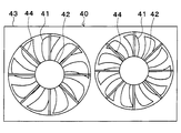
- the vehicle cooling device is provided with a blower 40 shown in FIG.
- the blower 40 is disposed on the vehicle rear side of the heat exchangers 10 and 11.
- the blower 40 includes a fan 41, a fan motor 42, and a shroud 43. In the example shown in FIG. 9, two sets of the fan 41 and the fan motor 42 are provided.
- the fan 41 is an axial flow type fan that blows air, and is configured to rotate around a rotation axis.
- the fan 41 has a plurality of blades arranged in a circle around the rotation axis.
- the fan motor 42 is an electric motor that provides rotational power to the fan 41, and the fan 41 is fixed to the rotation shaft of the fan motor 42.
- the shroud 43 has a circular opening corresponding to the fan 41.
- a fan motor 42 is fixed to the opening of the shroud 43 by a plurality of stays 44.
- the shroud 43 holds the fan motor 42 and guides the air flow so that the air flow induced by the fan 41 passes through the heat exchangers 10, 11.
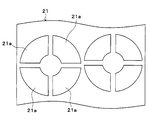
- the opening 21 a of the screen 21 is formed in accordance with the wind speed distribution of the heat exchangers 10 and 11. Specifically, the opening 21 a of the screen 21 is formed corresponding to a portion where the wind speed is equal to or more than a predetermined value in the heat exchangers 10 and 11. In the second embodiment, the portion where the wind speed is equal to or more than the predetermined value is a portion corresponding to the fan 41 in the heat exchangers 10 and 11.
- a plurality of fan-shaped openings 21a are arranged in a circle on the screen 21.
- the position and shape of the opening 21 a correspond to the fan 41.
- the opening part 21a is not formed in the site
- the opening 21a of the screen 21 is formed corresponding to only the portion of the heat exchangers 10 and 11 where the wind speed is high. Thereby, the heat exchangers 10 and 11 can be efficiently cooled while securing the Cd value.
- the shutter device 20 is disposed on the vehicle front side of the heat exchangers 10 and 11.
- the shutter device 20 is disposed on the vehicle rear side of the heat exchangers 10 and 11 without being limited thereto. May be
- the motor 24 for moving the screen 21 is disposed above the heat exchangers 10 and 11.
- the motor 24 is disposed below the heat exchangers 10 and 11 without being limited thereto.
- the motor 24 may be disposed on the right side or the left side of the heat exchangers 10 and 11. When the motor 24 is disposed on the right or left side of the heat exchangers 10 and 11, the screen 21 moves in the left and right direction.
- the winding unit 22 is rotated by the rotary motor 24 to move the screen 21.
- the present invention is not limited to this.
- the screen 21 is moved using a linear motor that moves linearly. You may make it
- a radiator for cooling engine cooling water and inverter cooling water of a hybrid vehicle was used as the heat exchangers 10 and 11 for adjusting the amount of ventilation with the shutter device 20.
- the present disclosure may be applied to different types of heat exchangers.
- a radiator for cooling cooling water heat-exchanged with the supercharged air is used as the heat exchanger of the present disclosure.
- a condenser that condenses the refrigerant of the refrigeration cycle can be used as the heat exchanger of the present disclosure.
- the heat exchanger that adjusts the amount of ventilation with the shutter device 20 may be a combination of heat exchangers in which the same type of heat exchange medium flows (for example, a radiator and a radiator, a condenser and a condenser) It may be a combination of exchangers (for example, a radiator and a condenser).
- the plurality of heat exchangers 10 and 11 for adjusting the amount of ventilation with the shutter device 20 are vertically stacked, but the present invention is not limited thereto. May be arranged side by side in the left-right direction.
- the plurality of heat exchangers 10, 11 may be arranged in the vehicle longitudinal direction.
- a heat exchanger having a large required cooling amount may be disposed on the front side of the vehicle, and a heat exchanger having a small required cooling amount may be disposed on the rear side of the vehicle.
- the amount of ventilation of the plurality of heat exchangers 10 and 11 is adjusted by the shutter device 20.
- the invention is not limited to this, the amount of ventilation of one heat exchanger is calculated by the shutter device 20. You may make it adjust.
- a plurality of types of heat exchange media may flow in one heat exchanger, or a configuration in which one type of heat exchange medium flows in one heat exchanger may be used.
- the inside of the heat exchanger is partitioned into a plurality of portions, and it can be regarded as a configuration in which the plurality of heat exchangers are integrated. For this reason, the amount of ventilation may be controlled for each portion where different heat exchange media flow.
- the amount of ventilation of each part may be made different.
- the temperature on the inflow side of the cooling water is high and the temperature on the outflow side of the cooling water is low. The amount of ventilation on the side should be reduced.
Abstract
熱交換媒体と外気との熱交換を行う車両用熱交換器(10、11)の通風量を調整するシャッター構造は、スクリーン(21)と、スクリーン巻取り部(22、23)とを備える。スクリーン(21)は、車両用熱交換器(10、11)の車両前方側または車両後方側に配置される。スクリーン巻取り部(22、23)は、スクリーン(21)を巻取ることで、スクリーン(21)を車両用熱交換器(10、11)に対して移動させることが可能である。スクリーン(21)の一部には、開口部(21a)が形成されている。
Description
本出願は、2017年10月12日に出願された日本特許出願2017-198278号に基づくもので、ここにその記載内容を援用する。
本開示は、車両用熱交換器のシャッター構造に関する。
従来より、車両用熱交換器の通風量を調整するために、車両用熱交換器にシャッターを設けることが知られている。このような熱交換器用シャッターとして、特許文献1では、並列配置した複数のブレードをモータによって開閉するグリルシャッターが提案されている。
しかしながら、特許文献1のシャッターでは、ブレードの開閉を1個のモータで行っているため、全ブレードが同じ角度で同時に開閉する。このため、一部のブレードのみを開放することができない。
例えばハイブリッド車両もしくは水冷式インタークーラを備える車両では、複数系統の冷却水回路が設けられており、天地方向で2個のラジエータが積層して2段重ねに配置されることがある。このような構成のラジエータに、特許文献1のシャッターを用いると、積層されたラジエータのうち一部のラジエータのみを冷却することができない。特許文献1のシャッターにおいて、一部のブレードを開放可能とするためには、ブレードを開閉するモータが複数必要となる。
また、従来のシャッターでは、シャッターを開く機会が増える。このため、熱交換器を通過する空気量が多くなり、結果としてCd値を低減可能な状況が少なくなる。
本開示は、簡易な構成で車両用熱交換器の必要な部位のみを冷却可能なシャッター構造を提供することを目的とする。
本開示の一態様において、熱交換媒体と外気との熱交換を行う車両用熱交換器の通風量を調整する車両用熱交換器のシャッター構造は、車両用熱交換器の車両前方側または車両後方側に配置されるスクリーンと、スクリーンを巻取ることで、スクリーンを車両用熱交換器に対して移動させることが可能な巻取り部とを備え、スクリーンの一部に開口部が形成されている。
これによれば、スクリーンを巻取るロール式のシャッター構造を用いることで、スクリーンを1個の駆動部で移動させることができる。また、スクリーンの一部に開口部を設けることで、複数の熱交換器のうち一部の熱交換器のみ、あるいは1つの熱交換器の一部のみを適切に冷却することが可能となる。これにより、簡易な構成で車両用熱交換器の必要な部位のみを冷却可能とすることができる。
(第1実施形態)
以下、第1実施形態について説明する。本実施形態の車両用冷却装置は、エンジンおよび走行用電動モータから車両走行用の駆動力を得るハイブリッド車両に搭載されている。エンジンの駆動力は、車両走行用として用いられるのみならず、発電機を作動させるためにも用いられる。発電機にて発電された電力を電池に蓄わえることができる。電池から出力される直流電力は、インバータで交流電力に変換して走行用モータに供給される。
以下、第1実施形態について説明する。本実施形態の車両用冷却装置は、エンジンおよび走行用電動モータから車両走行用の駆動力を得るハイブリッド車両に搭載されている。エンジンの駆動力は、車両走行用として用いられるのみならず、発電機を作動させるためにも用いられる。発電機にて発電された電力を電池に蓄わえることができる。電池から出力される直流電力は、インバータで交流電力に変換して走行用モータに供給される。
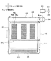
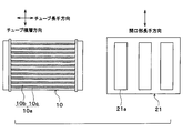
図1に示すように、本実施形態の車両用冷却装置は、第1熱交換器10、第2熱交換器11、シャッター装置20等を備えている。図1では、紙面手前側が車両前方側であり、紙面奥側が車両後方側である。図1では図示を省略しているが、熱交換器10、11の車両後方側に送風装置が設けられている。この送風装置によって、熱交換器10、11に外気が送風される。
本実施形態の熱交換器10、11は、冷却水(熱交換媒体)と外気とを熱交換して冷却水を冷却するラジエータである。本実施形態では、複数の熱交換器10、11を備えており、これらの熱交換器10、11には、異なる冷却水回路の冷却水が流通する。
本実施形態の車両用冷却装置には、複数の冷却水回路が設けられている。本実施形態の冷却水回路には、エンジン冷却水が循環するエンジン冷却水回路、インバータ冷却水が循環するインバータ冷却水回路が含まれている。第1熱交換器10は、エンジン冷却水回路に設けられており、エンジン冷却水が流通する。第2熱交換器11は、インバータ冷却水回路に設けられており、インバータ冷却水が流通する。つまり、複数の熱交換器10、11には、それぞれ別系統の冷却水が流通するようになっている。
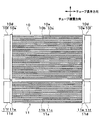
第1熱交換器10および第2熱交換器11は同様の構成を備えているので、第1熱交換器10の構成についてのみ説明する。図2に示すように、第1熱交換器10は、コア部10aと、コア部10aの両端部に組み付け配置されるヘッダタンク10dとを有している。
コア部10aは、チューブ10bおよびフィン10cからなる。チューブ10bは内部を冷却水が流れる管状部材である。複数のチューブ10bは並列して配置されている。本実施形態では、チューブ10bの長手方向が水平方向となり、チューブ10bの積層方向が鉛直方向となるように配置されている。フィン10cは、隣接するチューブ10bの間に接合されており、伝熱面積を増大させて冷却水と空気との熱交換を促進している。
ヘッダタンク10dは、チューブ10bの両端部において、複数のチューブ10bと連通している。ヘッダタンク10dは、チューブ10bが挿入接合されるコアプレート10eと、コアプレート10eとともにタンク空間を構成するタンク本体部10fとを有している。
図1~図3に示すように、第1熱交換器10と第2熱交換器11は、積層して配置されている。第1熱交換器10と第2熱交換器11は、チューブ積層方向が一致している。本実施形態では、第1熱交換器10が鉛直方向上側、第2熱交換器11が鉛直方向下側に配置されている。第1熱交換器10および第2熱交換器11は、車両前後方向からみて重なり合わないように配置されている。
図1に示すように、シャッター装置20は、スクリーン21を備えている。スクリーンは柔軟性を有するシート状部材であり、例えばフッ素樹脂シートを好適に用いることができる。本実施形態では、スクリーン21は、少なくとも熱交換器10、11のコア部10a、11aを覆うように配置されている。
シャッター装置20は、熱交換器10、11に対してスクリーン21を移動させることで、熱交換器10、11の通風量を調整できる。本実施形態では、スクリーン21は上下方向に移動可能となっている。
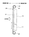
本実施形態のシャッター装置20は、スクリーン21を巻取ることでスクリーン21が移動可能なロール式構造となっている。本実施形態では、スクリーン21の両端部に巻取り部22、23が設けられている。第1巻取り部22はスクリーン21の上側端部に設けられ、第2巻取り部23はスクリーン21の下側端部に設けられている。第1巻取り部22は第1熱交換器10の上方に位置し、第2巻取り部23は第2熱交換器11の下方に位置している。第1巻取り部22と第2巻取り部23は、スクリーン巻き取り部に対応している。
第1巻取り部22には、モータ24の回転軸24aが接続されている。モータ24は、第1巻取り部22を回転駆動する駆動部である。モータ24を作動させることで、第1巻取り部22を回転させることができる。モータ24は、スクリーン21を巻取る方向とスクリーン21を送り出す方向に第1巻取り部22を回転駆動することができる。
第2巻取り部23には、バネ部材25が設けられている。バネ部材25としては、例えばねじりバネを用いることができる。バネ部材25は、第2巻取り部23にスクリーン21を巻取る方向にバネ力を作用させる。
第1巻取り部22にスクリーン21を巻取るようにモータ24を作動させることで、第2巻取り部23から第1巻取り部22に向かう方向にスクリーン21を移動させることができる。モータ24の回転を停止させることで、スクリーン21を停止させることができる。第1巻取り部22からスクリーン21を送り出すようにモータ24を作動させることで、第1巻取り部22から第2巻取り部23に向かう方向にスクリーン21を移動させることができる。
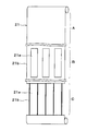
図4に示すように、スクリーン21の一部に開口部21aが形成されている。開口部21aでは、シート面の一部に穴が開いた状態となっている。スクリーン21における開口部21aが形成された部位は、連結部21bによってシート面がつながっている。開口部21aは、開口面積、開口位置、開口形状等の開口態様が異なる複数の開口パターンが設けられている。
スクリーン21の開口部21aを通過した外気が熱交換器10、11に供給される。このため、熱交換器10、11に対してスクリーン21を移動させることで、熱交換器10、11に対する開口部21aの位置が変わり、熱交換器10、11の通風量の調整を行うことができる。
また、開口部21aの開口面積を調整することで、開口部21aを通過する風量を調整でき、熱交換器10、11における開口部21aに対応する部位の通風量を調整できる。開口部21aの開口面積、開口位置、開口形状等は任意に設定可能であり、熱交換器10、11の必要冷却量に応じて設定することできる。熱交換器10、11の必要冷却量は、熱交換器10、11の必要通風量と言い換えることができる。開口部21aは、車両用冷却装置が搭載される車種毎に最適化すればよい。
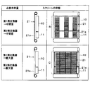
スクリーン21には、開口部21aの有無、開口部21aの開口面積等が異なる複数の領域が形成されている。これら複数の領域には、閉鎖領域A、中間開放領域B、最大開放領域Cが含まれている。
閉鎖領域Aは、開口部21aが形成されておらず、スクリーン21のシート面が全面に存在しており、熱交換器10、11に外気を通過させない領域である。中間開放領域21dおよび最大開放領域21eは、開口部21aが設けられ、熱交換器10、11に外気を通過させる領域である。
中間開放領域Bおよび最大開放領域Cでは、開口部21aの開口パターンが異なっている。具体的には、最大開放領域Cの方が中間開放領域Bよりも開口部21aの開口面積が大きくなっている。このため、最大開放領域Cの方が中間開放領域Bよりも熱交換器10、11の通風量が多くなる。図4に示す例では、最大開放領域Cは、連結部21bが紐状になっており、開口部21aの開口面積が最大になっている。
本実施形態では、スクリーン21の開口部21aは、熱交換器10、11の熱歪みを考慮して形成されている。この点について図5、図6を用いて説明する。なお、図5、図6では、第1熱交換器10のみを図示し、第2熱交換器11の図示を省略している。
図5に示すように、熱交換器10には、複数のチューブ10bが並列配置されている。スクリーン21の開口部21aを通過した外気が一部のチューブ10bのみに当たると、隣接するチューブ10bの温度差が大きくなる可能性がある。隣接するチューブ10bの温度差が大きくなると、チューブ10b間の熱膨張差に起因する熱歪みが発生し、チューブ10bが破損するおそれがある。
このため、本実施形態では、隣接するチューブ10bの温度差ができるだけ小さくなるように、スクリーン21の開口部21aを形成している。本実施形態の開口部21aは、熱交換器10のチューブ10bの長手方向と角度をずらして形成されている。本実施形態では、開口部21aが長方形となっており、開口部21aの長手方向がチューブ10bの長手方向とずれている。
開口部21aの長手方向は、チューブ10b、11bの長手方向とずれていればよい。本実施形態では、図5に示すように、開口部21aの長手方向がチューブ10b、11bの長手方向に対して直交しており、開口部21aの長手方向がチューブ10b、11bの積層方向と一致している。また、図6の変形例に示すように、開口部21aの長手方向がチューブ10b、11bの長手方向に対して斜めになっていてもよい。
開口部21aは、隣接するチューブ10b、11bに跨るように形成されている。図5、図6に示す例では、開口部21aは熱交換器10のすべてのチューブ10bに跨るように形成されているが、必ずしもすべてのチューブ10bに跨るように形成されている必要はない。
開口部21aは、隣接するチューブ10b、11bに当たる風量差が所定値以下となるように形成すればよい。換言すれば、開口部21aは、隣接するチューブ10b、11bの温度差が所定値以下となるように形成すればよい。
図1に示すように、車両用冷却装置には、制御装置30が設けられている。制御装置30は、CPU、ROMおよびRAM等を含む周知のマイクロコンピュータとその周辺回路から構成され、そのROM内に記憶された空調制御プログラムに基づいて各種演算、処理を行う。
制御装置30の入力側には、エンジン冷却水の水温を検出する第1水温センサ31、インバータ冷却水の水温を検出する第2水温センサ32が接続されている。制御装置30の出力側には、モータ24が接続されている。制御装置30は、モータ24の作動を制御することで、熱交換器10、11に対するスクリーン21の位置を制御することができる。
制御装置30は、第1水温センサ31で検出したエンジン冷却水の水温と、第2水温センサ32で検出したインバータ冷却水の水温に基づいて、モータ24の作動を制御する。これにより、第1熱交換器10の必要冷却量および第2熱交換器11の必要冷却量に応じてスクリーン21の位置を調整し、第1熱交換器10の通風量および第2熱交換器11の通風量を調整することができる。
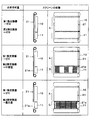
熱交換器10、11の通風量制御を図7、図8を用いて説明する。図7、図8は、熱交換器10、11の必要冷却量とスクリーン21の状態との関係を示している。図7、図8に示すスクリーン21の各状態の切替は、制御装置30がモータ24を制御することによって行われる。
図7の上段は、第1熱交換器10および第2熱交換器11の必要冷却量がゼロの場合を示している。この場合には、スクリーン21は、閉鎖領域Aが第1熱交換器10および第2熱交換器11に対応する位置にある。このため、第1熱交換器10および第2熱交換器11は通風量がゼロとなっている。
図7の中段は、第1熱交換器10の必要冷却量がゼロであり、第2熱交換器11の必要冷却量が中間値である場合を示している。この場合には、スクリーン21は、閉鎖領域Aが第1熱交換器10に対応する位置にあり、中間開放領域Bが第2熱交換器11に対応する位置にある。このため、第1熱交換器10は通風量がゼロとなり、第2熱交換器11は通風量が中間値となっている。
図7の下段は、第1熱交換器10の必要冷却量がゼロであり、第2熱交換器11の必要冷却量が最大値である場合を示している。この場合には、スクリーン21は、閉鎖領域Aが第1熱交換器10に対応する位置にあり、最大開放領域Cが第2熱交換器11に対応する位置にある。このため、第1熱交換器10は通風量がゼロとなり、第2熱交換器11は通風量が最大値となっている。
図8の上段は、第1熱交換器10および第2熱交換器11の必要冷却量が中間値の場合を示している。この場合には、スクリーン21は、中間開放領域Bが第1熱交換器10および第2熱交換器11に対応する位置にある。このため、第1熱交換器10および第2熱交換器11は通風量が中間値となっている。
図8の下段は、第1熱交換器10および第2熱交換器11の必要冷却量が最大値の場合を示している。この場合には、スクリーン21は、最大開放領域Cが第1熱交換器10および第2熱交換器11に対応する位置にある。このため、第1熱交換器10および第2熱交換器11は通風量が最大値となっている。
以上説明した本実施形態では、熱交換器10、11の通風量を調整するシャッター装置20として、スクリーン21を巻取って移動させることができるロール式シャッター装置を採用し、スクリーン21の一部に開口部21aが形成されている。これにより、1個のモータ24でスクリーン21を移動させることで、複数の熱交換器10、11のうち一部の熱交換器10、11のみを冷却することが可能となり、各熱交換器10、11の通風量を適切に調整することができる。
また、本実施形態のシャッター装置20では、複数の熱交換器10、11のうち冷却不要な熱交換器10、11はスクリーン21のシート面で覆われている。このため、不要な外気が熱交換器10、11に供給されず、Cd値を低減可能な状況を多く作り出すことができる。Cd値のCdとは、Coefficient of dragの略である。Cd値とは、空気抵抗係数であって、一般にCd値が小さいほど燃費が向上する。
また、本実施形態のシャッター装置20では、スクリーン21に形成した開口部21aを介して熱交換器10、11に外気が供給される。このため、開口部21aの開口面積、開口位置、開口形状等の開口態様が異なる開口パターンを複数設けることで、熱交換器10、11の通風量をきめ細かく調整することが可能となる。
また、本実施形態のシャッター装置20では、スクリーンの開口部21aをチューブ長手方向とずらして形成し、隣接するチューブ10b、11bに当たる風量差が所定値以下となるようにしている。これにより、開口部21aを通過した外気が複数のチューブ10b、11bのうち一部のチューブ10b、11bのみに当たることを抑制できる。この結果、隣接するチューブ10b、11bの温度差が大きくなることを抑制でき、熱交換器10、11で熱歪みが発生することを抑制できる。
また、本実施形態のシャッター装置20では、制御装置30が温度センサ31、32で検出した冷却水の温度に基づいてモータ24によるスクリーン21の巻取りを制御し、車両用熱交換器10、11に対するスクリーン21の位置を制御している。これにより、熱交換器10、11の必要冷却量に応じて熱交換器10、11の通風量を適切に調整することができる。
(第2実施形態)
第2実施形態を図9、図10を用いて説明する。上記第1実施形態と同様の部分については説明を省略し、異なる部分についてのみ説明する。
第2実施形態を図9、図10を用いて説明する。上記第1実施形態と同様の部分については説明を省略し、異なる部分についてのみ説明する。
上記第1実施形態では、熱交換器10、11の必要冷却量に応じてスクリーン21の開口部21aを形成したが、熱交換器10、11の風速分布に応じてスクリーン21の開口部21aを形成している。
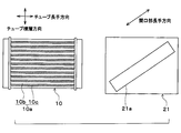
車両用冷却装置は、図9に示す送風装置40を備えている。送風装置40は、熱交換器10、11の車両後方側に配置されている。送風装置40は、ファン41と、ファンモータ42と、シュラウド43とを備えている。図9に示す例では、ファン41およびファンモータ42が2組設けられている。
ファン41は、空気を送風する軸流式の送風ファンであり、回転軸を中心に回転するように構成されている。ファン41は、回転軸の周囲に複数のブレードが円形に配置されている。ファンモータ42は、ファン41に回転動力を与える電動機であり、ファンモータ42の回転軸にファン41が固定されている。
シュラウド43には、ファン41に対応して円形の開口部が形成されている。シュラウド43の開口部には、複数のステー44によってファンモータ42が固定されている。シュラウド43は、ファンモータ42を保持すると共に、ファン41により誘起される空気流れが熱交換器10、11を通過するように空気流れをガイドする。
送風装置40では、ファン41によって空気流れが発生する一方、ファンモータ42では空気流れが発生しない。このため、熱交換器10、11では、ファン41に対応する部位の風速が速くなり、ファンモータ42に対応する部位の風速が遅くなる。つまり、熱交換器10、11では、送風装置40の送風によって風速分布が生じる。
本第2実施形態では、スクリーン21の開口部21aを熱交換器10、11の風速分布に応じて形成している。具体的には、熱交換器10、11で風速が所定値以上となる部位に対応してスクリーン21の開口部21aを形成している。本第2実施形態において、風速が所定値以上となる部位は、熱交換器10、11におけるファン41に対応する部位である。
図10に示す例では、スクリーン21に複数の扇形状の開口部21aが円形に配置されている。開口部21aの位置および形状は、ファン41に対応している。そして、風速が低くなるファンモータ42に対応する部位には開口部21aを形成していない。
以上説明した本第2実施形態では、熱交換器10、11における風速が速い部位のみに対応してスクリーン21の開口部21aを形成している。これにより、Cd値を確保したまま、熱交換器10、11の冷却を効率よく行うことができる。
(他の実施形態)
本開示は上述の実施形態に限定されることなく、趣旨を逸脱しない範囲内で、以下のように種々変形可能である。また、上記各実施形態に開示された手段は、実施可能な範囲で適宜組み合わせてもよい。
本開示は上述の実施形態に限定されることなく、趣旨を逸脱しない範囲内で、以下のように種々変形可能である。また、上記各実施形態に開示された手段は、実施可能な範囲で適宜組み合わせてもよい。
(1)上記各実施形態では、シャッター装置20を熱交換器10、11の車両前方側に配置したが、これに限らず、シャッター装置20を熱交換器10、11の車両後方側に配置してもよい。
(2)上記各実施形態では、スクリーン21を移動させるモータ24を熱交換器10、11の上側に配置したが、これに限らず、モータ24を熱交換器10、11の下側に配置してもよく、モータ24を熱交換器10、11の右側または左側に配置してもよい。モータ24を熱交換器10、11の右側または左側に配置する場合には、スクリーン21は左右方向に移動することとなる。
(3)上記各実施形態では、回転式のモータ24で巻取り部22を回転させてスクリーン21を移動させるようにしたが、これに限らず、直線運動するリニアモータを用いてスクリーン21を移動させるようにしてもよい。
(4)上記各実施形態では、シャッター装置20で通風量を調整する熱交換器10、11としてハイブリッド車両のエンジン冷却水やインバータ冷却水を冷却するためのラジエータを用いた例について説明したが、本開示を異なる種類の熱交換器に適用してもよい。例えば、過給機で加圧された過給気を冷却する水冷式インタークーラを備える車両であれば、本開示の熱交換器として過給気と熱交換した冷却水を冷却するラジエータを用いることができる。あるいは、本開示の熱交換器として、冷凍サイクルの冷媒を凝縮させるコンデンサを用いることができる。
シャッター装置20で通風量を調整する熱交換器は、同種の熱交換媒体が流通する熱交換器の組み合わせ(例えばラジエータとラジエータ、コンデンサとコンデンサ)でもよく、異なる種類の熱交換媒体が流通する熱交換器の組み合わせ(例えばラジエータとコンデンサ)でもよい。
(5)上記各実施形態では、シャッター装置20で通風量を調整する複数の熱交換器10、11を上下方向に積層するようにしたが、これに限らず、複数の熱交換器10、11を左右方向に並べて配置してもよい。
また、複数の熱交換器10、11の必要冷却量がそれぞれ異なる場合には、複数の熱交換器10、11を車両前後方向に配置してもよい。この場合、必要冷却量が大きい熱交換器を車両前方側に配置し、必要冷却量が小さい熱交換器を車両後方側に配置すればよい。
(6)上記各実施形態では、シャッター装置20で複数の熱交換器10、11の通風量を調整するようにしたが、これに限らず、シャッター装置20で1つの熱交換器の通風量を調整するようにしてもよい。この場合、1つの熱交換器に複数種類の熱交換媒体が流通する構成でもよく、1つの熱交換器に1種類の熱交換媒体が流通する構成でもよい。
1つの熱交換器に複数種類の熱交換媒体が流通する構成では、熱交換器の内部が複数の部位に仕切られており、複数の熱交換器が一体化した構成とみなすことができる。このため、異なる熱交換媒体が流通する部位毎に通風量の制御を行えばよい。
1つの熱交換器に1種類の熱交換媒体が流通する構成では、熱交換器に必要冷却量が異なる複数の部位が存在する場合に、部位毎の通風量を異ならせればよい。例えば熱交換器では、冷却水の流入側の温度が高くなり、冷却水の流出側の温度が低くなることが通常であるので、冷却水の流入側の通風量を多くし、冷却水の流出側の通風量を少なくすればよい。
Claims (6)
- 熱交換媒体と外気との熱交換を行う車両用熱交換器(10、11)の通風量を調整する車両用熱交換器のシャッター構造であって、
前記車両用熱交換器の車両前方側または車両後方側に配置されるスクリーン(21)と、
前記スクリーンを巻取ることで、前記スクリーンを前記車両用熱交換器に対して移動させることが可能なスクリーン巻取り部(22、23)とを備え、
前記スクリーンの一部に開口部(21a)が形成されている車両用熱交換器のシャッター構造。 - 前記開口部は、開口態様が異なる複数の開口パターンを有している請求項1に記載の車両用熱交換器のシャッター構造。
- 前記車両用熱交換器は、複数の車両用熱交換器のひとつであり、
前記複数の車両用熱交換器は、異なる前記熱交換媒体が流通する請求項1または2に記載の車両用熱交換器のシャッター構造。 - 前記車両用熱交換器は、前記熱交換媒体が流通する複数のチューブ(10b、11b)を備えており、
前記開口部は、前記複数のチューブのうち隣接するチューブに当たる風量差が所定値以下となるように形成されている請求項1ないし3のいずれか1つに記載の車両用熱交換器のシャッター構造。 - 前記開口部の開口面積を調整することで、前記車両用熱交換器における当該開口部に対応する部位の通風量を調整可能となっている請求項1ないし4のいずれか1つに記載の車両用熱交換器のシャッター構造。
- 前記車両用熱交換器に外気を通過させる送風装置(40)を備え、
前記送風装置を作動させることで、前記車両用熱交換器を通過する外気の風速分布が発生し、
前記開口部は、前記車両用熱交換器を通過する外気の風速が所定値以上となる部位に対応して形成されている請求項1ないし5のいずれか1つに記載の車両用熱交換器のシャッター構造。
Priority Applications (2)
| Application Number | Priority Date | Filing Date | Title |
|---|---|---|---|
| CN201880065734.4A CN111201149A (zh) | 2017-10-12 | 2018-08-21 | 车辆用热交换器的风门构造 |
| US16/814,609 US20200208925A1 (en) | 2017-10-12 | 2020-03-10 | Shutter structure of heat exchanger for vehicle |
Applications Claiming Priority (2)
| Application Number | Priority Date | Filing Date | Title |
|---|---|---|---|
| JP2017198278A JP2019073049A (ja) | 2017-10-12 | 2017-10-12 | 車両用熱交換器のシャッター構造 |
| JP2017-198278 | 2017-10-12 |
Related Child Applications (1)
| Application Number | Title | Priority Date | Filing Date |
|---|---|---|---|
| US16/814,609 Continuation US20200208925A1 (en) | 2017-10-12 | 2020-03-10 | Shutter structure of heat exchanger for vehicle |
Publications (1)
| Publication Number | Publication Date |
|---|---|
| WO2019073694A1 true WO2019073694A1 (ja) | 2019-04-18 |
Family
ID=66101376
Family Applications (1)
| Application Number | Title | Priority Date | Filing Date |
|---|---|---|---|
| PCT/JP2018/030828 WO2019073694A1 (ja) | 2017-10-12 | 2018-08-21 | 車両用熱交換器のシャッター構造 |
Country Status (4)
| Country | Link |
|---|---|
| US (1) | US20200208925A1 (ja) |
| JP (1) | JP2019073049A (ja) |
| CN (1) | CN111201149A (ja) |
| WO (1) | WO2019073694A1 (ja) |
Cited By (5)
| Publication number | Priority date | Publication date | Assignee | Title |
|---|---|---|---|---|
| WO2021123552A1 (fr) * | 2019-12-20 | 2021-06-24 | Valeo Systemes Thermiques | Dispositif de ventilation pour module de refroidissement de véhicule automobile et module de refroidissement pour véhicule automobile comprenant un tel dispositif de ventilation |
| FR3109335A1 (fr) * | 2020-04-20 | 2021-10-22 | Valeo Systemes Thermiques | Dispositif de régulation d’un flux d’air d’un véhicule automobile |
| CN113619542A (zh) * | 2020-05-09 | 2021-11-09 | 上海汽车集团股份有限公司 | 一种车辆前置散热系统及车辆 |
| US11279222B2 (en) * | 2019-11-11 | 2022-03-22 | Hyundai Motor Company | Cooling fan assembly for vehicle |
| DE102021206449A1 (de) | 2021-06-23 | 2022-12-29 | Volkswagen Aktiengesellschaft | Kühleranordnung für ein Kraftfahrzeug, Kühlerpaket und Verschlussvorrichtung für ein Kühlerpaket |
Families Citing this family (5)
| Publication number | Priority date | Publication date | Assignee | Title |
|---|---|---|---|---|
| KR20210066557A (ko) * | 2019-11-28 | 2021-06-07 | 현대자동차주식회사 | 차량의 인터쿨러 |
| CA3225804A1 (en) * | 2021-08-09 | 2023-02-16 | Jeffrey Bruce MANHIRE | Center-opening panel for controlling air flow through a heat exchanger |
| WO2023043881A2 (en) * | 2021-09-15 | 2023-03-23 | Magna Exteriors Inc. | An air flow metering device for controlling the flow of air into a vehicle passage |
| CN113715609A (zh) * | 2021-09-30 | 2021-11-30 | 东风商用车有限公司 | 一种多功能挡帘装置及车头结构 |
| WO2023187443A1 (en) * | 2022-03-29 | 2023-10-05 | Volvo Truck Corporation | Wind shielding system and method for regulating airflow to radiator cooling package of vehicle |
Citations (2)
| Publication number | Priority date | Publication date | Assignee | Title |
|---|---|---|---|---|
| US20080289794A1 (en) * | 2005-09-12 | 2008-11-27 | Frank Joseph Leitch | Vehicle cooling assembly having a protective screen |
| JP2017030504A (ja) * | 2015-07-31 | 2017-02-09 | いすゞ自動車株式会社 | エンジン用熱交換器の通風量制御機構 |
Family Cites Families (7)
| Publication number | Priority date | Publication date | Assignee | Title |
|---|---|---|---|---|
| JP4473071B2 (ja) * | 2004-08-20 | 2010-06-02 | トヨタ自動車株式会社 | 車両用熱交換器 |
| SE530032C2 (sv) * | 2006-06-30 | 2008-02-12 | Scania Cv Abp | Kylaranordning för ett motorfordon |
| JP2008106982A (ja) * | 2006-10-25 | 2008-05-08 | Calsonic Kansei Corp | 車両用熱交換器のシャッター構造 |
| JP2008184034A (ja) * | 2007-01-30 | 2008-08-14 | Nissan Motor Co Ltd | 熱交換器冷却構造 |
| JP2010089523A (ja) * | 2008-10-03 | 2010-04-22 | Toyota Motor Corp | 車両用冷却装置 |
| JP2016080250A (ja) * | 2014-10-16 | 2016-05-16 | 株式会社デンソー | 車両用熱交換器のシャッター構造 |
| JP6488994B2 (ja) * | 2015-11-26 | 2019-03-27 | 株式会社デンソー | 車両用熱媒体回路 |
-
2017
- 2017-10-12 JP JP2017198278A patent/JP2019073049A/ja active Pending
-
2018
- 2018-08-21 CN CN201880065734.4A patent/CN111201149A/zh active Pending
- 2018-08-21 WO PCT/JP2018/030828 patent/WO2019073694A1/ja active Application Filing
-
2020
- 2020-03-10 US US16/814,609 patent/US20200208925A1/en not_active Abandoned
Patent Citations (2)
| Publication number | Priority date | Publication date | Assignee | Title |
|---|---|---|---|---|
| US20080289794A1 (en) * | 2005-09-12 | 2008-11-27 | Frank Joseph Leitch | Vehicle cooling assembly having a protective screen |
| JP2017030504A (ja) * | 2015-07-31 | 2017-02-09 | いすゞ自動車株式会社 | エンジン用熱交換器の通風量制御機構 |
Cited By (7)
| Publication number | Priority date | Publication date | Assignee | Title |
|---|---|---|---|---|
| US11279222B2 (en) * | 2019-11-11 | 2022-03-22 | Hyundai Motor Company | Cooling fan assembly for vehicle |
| WO2021123552A1 (fr) * | 2019-12-20 | 2021-06-24 | Valeo Systemes Thermiques | Dispositif de ventilation pour module de refroidissement de véhicule automobile et module de refroidissement pour véhicule automobile comprenant un tel dispositif de ventilation |
| FR3105366A1 (fr) * | 2019-12-20 | 2021-06-25 | Valeo Systemes Thermiques | Dispositif de ventilation pour module de refroidissement de véhicule automobile et module de refroidissement pour véhicule automobile comprenant un tel dispositif de ventilation |
| FR3109335A1 (fr) * | 2020-04-20 | 2021-10-22 | Valeo Systemes Thermiques | Dispositif de régulation d’un flux d’air d’un véhicule automobile |
| WO2021214001A1 (fr) * | 2020-04-20 | 2021-10-28 | Valeo Systemes Thermiques | Dispositif de regulation d'un flux d'air d'un vehicule automobile |
| CN113619542A (zh) * | 2020-05-09 | 2021-11-09 | 上海汽车集团股份有限公司 | 一种车辆前置散热系统及车辆 |
| DE102021206449A1 (de) | 2021-06-23 | 2022-12-29 | Volkswagen Aktiengesellschaft | Kühleranordnung für ein Kraftfahrzeug, Kühlerpaket und Verschlussvorrichtung für ein Kühlerpaket |
Also Published As
| Publication number | Publication date |
|---|---|
| US20200208925A1 (en) | 2020-07-02 |
| JP2019073049A (ja) | 2019-05-16 |
| CN111201149A (zh) | 2020-05-26 |
Similar Documents
| Publication | Publication Date | Title |
|---|---|---|
| WO2019073694A1 (ja) | 車両用熱交換器のシャッター構造 | |
| JP5216613B2 (ja) | 車両用冷却装置 | |
| US8919470B2 (en) | Grille shutter device | |
| JP4384066B2 (ja) | 車両冷却システム | |
| JP2019142299A (ja) | 車両用冷却装置 | |
| US20130252531A1 (en) | Grill shutter device | |
| JP5945116B2 (ja) | 車両用アクティブエアフラップ装置 | |
| WO2018092527A1 (ja) | 車両の気流循環構造 | |
| JP6512158B2 (ja) | 車両用冷却システム | |
| WO2016059766A1 (ja) | 車両用熱交換器のシャッター構造 | |
| WO2016079938A1 (ja) | エンジンルーム通風構造 | |
| JP4323307B2 (ja) | 車両用熱交換器システム | |
| KR101219344B1 (ko) | 차량용 냉각공기 유입량 조절 장치 및 이를 이용한 하이브리드 차량용 냉각 장치 | |
| JP2014201278A (ja) | 車両用消費電力制御装置 | |
| JP2010195287A (ja) | 車両用空調装置 | |
| JP2007186047A (ja) | 車両用熱交換器 | |
| JP6819522B2 (ja) | 熱交換システム | |
| JP4367294B2 (ja) | 車両用水冷式内燃機関の冷却装置 | |
| WO2015059890A1 (ja) | 冷却システム | |
| WO2019058810A1 (ja) | 熱交換システム | |
| JP2007118651A (ja) | 車両用冷却装置 | |
| JP2005163758A (ja) | 熱交換装置 | |
| JP2008207569A (ja) | 燃料電池搭載車両の冷却システム、冷却制御方法 | |
| JP5130083B2 (ja) | 内燃機関の廃熱利用装置 | |
| JPH04163230A (ja) | 冷却装置 |
Legal Events
| Date | Code | Title | Description |
|---|---|---|---|
| 121 | Ep: the epo has been informed by wipo that ep was designated in this application |
Ref document number: 18866669 Country of ref document: EP Kind code of ref document: A1 |
|
| NENP | Non-entry into the national phase |
Ref country code: DE |
|
| 122 | Ep: pct application non-entry in european phase |
Ref document number: 18866669 Country of ref document: EP Kind code of ref document: A1 |