WO2019069879A1 - 吸収体の製造方法 - Google Patents
吸収体の製造方法 Download PDFInfo
- Publication number
- WO2019069879A1 WO2019069879A1 PCT/JP2018/036766 JP2018036766W WO2019069879A1 WO 2019069879 A1 WO2019069879 A1 WO 2019069879A1 JP 2018036766 W JP2018036766 W JP 2018036766W WO 2019069879 A1 WO2019069879 A1 WO 2019069879A1
- Authority
- WO
- WIPO (PCT)
- Prior art keywords
- sheet piece
- sheet
- absorber
- unit
- manufacturing
- Prior art date
Links
Images


Classifications
-
- A—HUMAN NECESSITIES
- A61—MEDICAL OR VETERINARY SCIENCE; HYGIENE
- A61F—FILTERS IMPLANTABLE INTO BLOOD VESSELS; PROSTHESES; DEVICES PROVIDING PATENCY TO, OR PREVENTING COLLAPSING OF, TUBULAR STRUCTURES OF THE BODY, e.g. STENTS; ORTHOPAEDIC, NURSING OR CONTRACEPTIVE DEVICES; FOMENTATION; TREATMENT OR PROTECTION OF EYES OR EARS; BANDAGES, DRESSINGS OR ABSORBENT PADS; FIRST-AID KITS
- A61F13/00—Bandages or dressings; Absorbent pads
- A61F13/15—Absorbent pads, e.g. sanitary towels, swabs or tampons for external or internal application to the body; Supporting or fastening means therefor; Tampon applicators
- A61F13/53—Absorbent pads, e.g. sanitary towels, swabs or tampons for external or internal application to the body; Supporting or fastening means therefor; Tampon applicators characterised by the absorbing medium
-
- D—TEXTILES; PAPER
- D04—BRAIDING; LACE-MAKING; KNITTING; TRIMMINGS; NON-WOVEN FABRICS
- D04H—MAKING TEXTILE FABRICS, e.g. FROM FIBRES OR FILAMENTARY MATERIAL; FABRICS MADE BY SUCH PROCESSES OR APPARATUS, e.g. FELTS, NON-WOVEN FABRICS; COTTON-WOOL; WADDING ; NON-WOVEN FABRICS FROM STAPLE FIBRES, FILAMENTS OR YARNS, BONDED WITH AT LEAST ONE WEB-LIKE MATERIAL DURING THEIR CONSOLIDATION
- D04H1/00—Non-woven fabrics formed wholly or mainly of staple fibres or like relatively short fibres
- D04H1/70—Non-woven fabrics formed wholly or mainly of staple fibres or like relatively short fibres characterised by the method of forming fleeces or layers, e.g. reorientation of fibres
- D04H1/72—Non-woven fabrics formed wholly or mainly of staple fibres or like relatively short fibres characterised by the method of forming fleeces or layers, e.g. reorientation of fibres the fibres being randomly arranged
- D04H1/732—Non-woven fabrics formed wholly or mainly of staple fibres or like relatively short fibres characterised by the method of forming fleeces or layers, e.g. reorientation of fibres the fibres being randomly arranged by fluid current, e.g. air-lay
-
- D—TEXTILES; PAPER
- D06—TREATMENT OF TEXTILES OR THE LIKE; LAUNDERING; FLEXIBLE MATERIALS NOT OTHERWISE PROVIDED FOR
- D06H—MARKING, INSPECTING, SEAMING OR SEVERING TEXTILE MATERIALS
- D06H7/00—Apparatus or processes for cutting, or otherwise severing, specially adapted for the cutting, or otherwise severing, of textile materials
- D06H7/02—Apparatus or processes for cutting, or otherwise severing, specially adapted for the cutting, or otherwise severing, of textile materials transversely
Definitions
- the present invention relates to a method of manufacturing an absorbent for an absorbent article.
- an absorber used for absorbent articles such as a disposable diaper, a sanitary napkin, and an incontinence pad
- an absorber including, for example, pulp fibers and synthetic fibers is known.
- a method for producing an absorbent containing pulp fibers and synthetic fibers for example, Patent Document 1 is known.
- Patent Document 1 describes an absorbent article in which a non-woven fabric having a three-dimensional structure in which fibers are bonded in advance is formed, and then the non-woven fabric is crushed to form non-woven fabric pieces, and the non-woven fabric pieces are mixed with hydrophilic fibers. A method of making the absorber is described. Further, Patent Document 1 describes that a cutter mill method is adopted as a means for crushing a non-woven fabric.
- the present invention is a method of producing an absorbent for an absorbent article comprising synthetic fibers.
- the present invention comprises a conveying step of conveying a plurality of sheet pieces containing the synthetic fiber to a stacking unit using a conveying unit.
- the present invention includes an accumulation step of accumulating a plurality of the sheet pieces conveyed in the conveyance step in the accumulation portion to obtain an accumulation body which is a component member of an absorber.
- the sheet piece is transported in a scattered state by the air flow generated in the transport unit.
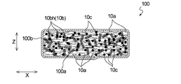
- FIG. 1 is a cross-sectional view showing a preferred embodiment of an absorbent body produced by the method for producing an absorbent body of the present invention.
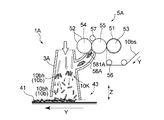
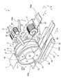
- FIG. 2 is a schematic side view which shows 1st Embodiment of the manufacturing apparatus of the absorber manufactured by the manufacturing method of the absorber of this invention.
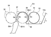
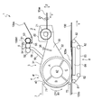
- FIG. 3 is an enlarged side view of a supply unit provided in the manufacturing apparatus shown in FIG.
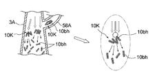
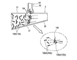
- FIG. 4 is a view schematically showing a state in which a block of a sheet piece collides with an air flow in a duct provided in the manufacturing apparatus shown in FIG. 2 to disperse and convey the sheet piece.
- FIG. 5 is a schematic perspective view which shows 2nd Embodiment of the manufacturing apparatus which manufactures the absorber shown in FIG.
- FIG. 6 is a schematic side view of the manufacturing apparatus shown in FIG. 5 as viewed from the side.
- FIG. 7 is a view schematically showing a state in which a block of a sheet piece collides with an air flow in a duct provided in the manufacturing apparatus shown in FIG. 5 to disperse and convey the sheet piece.
- FIG. 8 is a view schematically showing a state in which the hydrophilic fiber collides with a block of sheet pieces and the sheet pieces are dispersed and conveyed in the duct provided in the manufacturing apparatus shown in FIG.
- FIG. 9 is a view schematically showing a state in which the absorbent particles collide with a block of sheet pieces and the sheet pieces are dispersed and conveyed in the duct provided in the manufacturing apparatus shown in FIG.
- FIG. 9 is a view schematically showing a state in which the absorbent particles collide with a block of sheet pieces and the sheet pieces are dispersed and conveyed in the duct provided in the manufacturing apparatus shown in FIG.
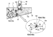
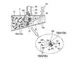
- FIG. 10 is a view schematically showing a state in which a block of a sheet piece collides with a hydrophilic fiber in a duct provided in the manufacturing apparatus shown in FIG. 5 to disperse and convey the sheet piece.
- FIG. 11 is a view schematically showing a state in which a block of a sheet piece collides with absorbent particles in a duct provided in the manufacturing apparatus shown in FIG. 5 to disperse and convey the sheet piece.
- the present invention relates to a method of manufacturing an absorber in which distribution unevenness of the sheet pieces is suppressed in the method of manufacturing an absorber containing sheet pieces containing synthetic fibers.
- the production method of the present invention is a method for producing an absorbent containing synthetic fibers.
- the absorbent produced in the present invention is an absorbent for an absorbent article.
- An absorbent article is mainly used to absorb and hold body fluids excreted from the body such as urine and menstrual blood.
- Absorbent articles include, but are not limited to, for example, disposable diapers, sanitary napkins, incontinence pads, panty liners, etc., and widely include articles used for absorbing fluid discharged from the human body. Do.
- the absorbent article typically comprises a liquid-permeable top sheet, a liquid-impermeable or water-repellent back sheet, and a liquid-retaining absorbent interposed between the two sheets.
- the absorber is an absorber formed by the method for producing an absorber of the present invention.
- FIG. 1 shows a cross-sectional view of an embodiment of an absorber 100 manufactured by the method of manufacturing an absorber according to an embodiment of the present invention.
- Absorbent body 100 contains synthetic fiber 10b.
- the absorbent body 100 includes an aggregate 100 a including not only the synthetic fibers 10 b but also the hydrophilic fibers 10 a and the absorbent particles 10 c.
- “including the synthetic fiber 10b” means having the sheet piece 10bh containing the synthetic fiber 10b.
- the absorber 100 may be a single layer or a plurality of layers as long as it includes the synthetic fiber 10b, but the accumulation of single layers in which the hydrophilic fiber 10a, the synthetic fiber 10b and the absorbent particle 10c are uniformly dispersed It has a body 100a.
- the stack 100a is a component of the absorber 100, and the absorber 100 is formed by covering the stack 100a with a core wrap sheet 100b.
- the absorbent body 100 has a longitudinally long shape corresponding to the front-rear direction of the wearer when the absorbent article is worn.
- the stacked body 100a includes a plurality of sheet pieces 10bh (hereinafter, also simply referred to as sheet pieces 10bh) including the synthetic fibers 10b, and each sheet piece 10bh has a substantially rectangular shape.
- the average length of each sheet piece 10bh is preferably 0.3 mm or more and 30 mm or less, more preferably 1 mm or more and 15 mm or less, and particularly preferably 2 mm or more and 10 mm or less.
- the average length indicates the average value of the lengths of the sides in the longitudinal direction when each sheet piece 10bh has a rectangular shape.
- each sheet piece 10bh has a square shape, it indicates the average value of the lengths of any one side of the four sides.
- the average width of each sheet piece 10bh is preferably 0.1 mm or more and 10 mm or less, more preferably 0.3 mm or more and 6 mm or less, and particularly preferably 0.5 mm or more and 5 mm or less.
- the average width indicates the average value of the lengths of the sides in the short direction when each sheet piece 10bh has a rectangular shape.
- each sheet piece 10bh When each sheet piece 10bh has a square shape, it indicates the average value of the lengths of any one side of the four sides.
- the average width of the sheet piece 10bh is 0.1 mm or more, it is easy to form a sparse structure in the absorber 100, and when it is 10 mm or less, it is difficult for the wearer to feel discomfort due to the absorber 100. It is hard to produce nonuniformity in absorption performance by the position in 100.
- the various things conventionally used for the absorber for absorbent articles can be used without a restriction
- the hydrophilic fibers 10a include pulp fibers, rayon fibers, cotton fibers and the like.
- the synthetic fiber 10 b include short fibers such as polyethylene, polypropylene and polyethylene terephthalate.
- the sheet piece 10bh is not particularly limited as long as it has a sheet shape, but a non-woven fabric is preferable.
- absorbent particles 10c are also contained in the raw material constituting the absorber 100.
- Examples of the absorbent particles 10c include starch-based, cellulose-based, synthetic polymer-based, and superabsorbent polymer-based ones.
- As the superabsorbent polymer for example, those comprising starch-acrylic acid (salt) graft copolymer, saponified starch-acrylonitrile copolymer, cross-linked product of sodium carboxymethyl cellulose, acrylic acid (salt) polymer, etc. It can be used.
- a component which constitutes absorber 100 a deodorizer, an antibacterial agent, etc. can also be used if needed.
- Examples of the core wrap sheet 100 b include tissue paper and liquid-permeable nonwoven fabric.
- the raw material of the aggregate 100a which is a component of the absorber of the present invention, may contain at least the synthetic fiber 10b, but in the above-described absorber 100, at least one sheet piece 10bh and at least one sheet piece 10bh different from each other. Contains different kinds of different materials.
- the dissimilar material contains the absorbent particles 10c, and further contains the hydrophilic fibers 10a. That is, in addition to the synthetic fiber 10b, the absorbent body 100 shown in FIG. 1 includes the hydrophilic fiber 10a and the absorbent particle 10c.
- FIG. 2 shows a schematic configuration of the manufacturing apparatus 1A.
- the manufacturing apparatus 1A includes, as shown in FIG. 2, a transport unit 3A that transports the raw material of the absorber 100, and a supply unit 5A that supplies a plurality of sheet pieces 10bh to the inside of the transport unit 3A from the middle of the transport unit 3A.
- An accumulation conveyance unit 43 is disposed downstream of the conveyance unit 3A and has an accumulation unit that accumulates the raw materials of the absorber 100.
- the stacking recess 41 which is an example of the stacking unit, is disposed in the stacking and transporting unit 43.
- the direction in which the belt-like synthetic fiber sheet 10bs including the synthetic fiber 10b and the absorbent 100 are conveyed is the Y direction, the direction orthogonal to the conveying direction, and the width direction of the synthetic fiber sheet 10bs and the absorbent 100 which are conveyed.
- Is the X direction, and the thickness direction of the conveyed synthetic fiber sheet 10bs and the absorber 100 is the Z direction.
- the first direction described later is a direction extending in the transport direction Y, and means a direction in which the angle formed with the transport direction Y is less than 45 degrees. In the first embodiment and the second embodiment described later, the first direction coincides with the direction parallel to the transport direction Y.
- the 2nd direction mentioned later is a direction which intersects with the 1st direction.
- the second direction is a direction orthogonal to the first direction, and coincides with a direction parallel to the width direction X of the synthetic fiber sheet 10bs to be conveyed and the absorber 100. There is.
- the transport unit 3 ⁇ / b> A is formed in a hollow cylindrical shape whose upstream side and downstream side are open.
- a blower fan (not shown) is disposed at the opening on the upstream side of the transport unit 3A.
- an accumulation conveyance unit 43 traveling in the conveyance direction Y is disposed at the opening on the downstream side of the conveyance unit 3A.
- the stacking and conveying portion 43 has the stacking recess 41 along the transport direction Y so that the opening of the stacking recess 41 is directed to the transport portion 3A.
- the transport section 3A extends over the entire width of the accumulation transport section 43.
- an air flow that causes the plurality of sheet pieces 10bh to flow toward the accumulation recess 41 of the accumulation conveyance unit 43 is generated by the operation of a blower fan (not illustrated). That is, the inside of the transport unit 3A is the flow path 30.
- the supply unit 5A is a cutter blade 51 that cuts a belt-like synthetic fiber sheet 10bs including the synthetic fiber 10b into a sheet piece 10bh by cutting it in a first direction and a second direction at a predetermined length.
- supply part 5A has supply nozzle 58A which supplies sheet piece 10bh formed using cutter blades 51 and 52.
- the supply unit 5A has a first cutter roller 53 having a plurality of cutter blades 51 for cutting in a first direction, and a second cutter roller 54 having a plurality of cutter blades 52 for cutting in a second direction. doing.
- the supply unit 5A includes one receiving roller 55 disposed to face the first cutter roller 53 and the second cutter roller 54.
- the entire outer periphery of the first cutter roller 53 is continuously formed on the surface of the first cutter roller 53 along the circumferential direction of the first cutter roller 53.
- a plurality of cutter blades 51, 51, 51,... Extending in parallel are arranged in the axial direction (X direction) of the first cutter roller 53.
- the first cutter roller 53 receives power from a motor such as a motor and rotates in the direction of arrow R3. The distance between the cutter blades 51, 51, 51, ...
- the width of the sheet piece 10bh formed by cutting (the length in the short direction, the length in the X direction) Generally correspond to the More precisely, the synthetic fiber sheet 10bs is cut in a state of being shrunk in the width direction X depending on the tension at the time of sheet conveyance, so that the tension is released in the finished sheet piece 10bh.
- the width of the sheet piece 10bh may be wider than the interval between the blades 51, 51, 51,.
- the surface of the second cutter roller 54 is continuous over the entire width of the second cutter roller 54 along the axial direction of the second cutter roller 54.
- a plurality of cutter blades 52, 52, 52,... Extending in the circumferential direction are arranged at intervals in the circumferential direction of the second cutter roller 54.
- the second cutter roller 54 receives power from a motor such as a motor and rotates in the direction of arrow R4.
- the receiving roller 55 is a flat roller whose surface is flat.
- the receiving roller 55 receives power from a motor such as a motor and rotates in the direction of the arrow R5.
- the supply unit 5A is configured to receive the receiving roller 55 and the first cutter from the upstream side to the downstream side in the rotation direction (arrow R5 direction) on the opposing surface of the receiving roller 55.
- the cutter rollers 54 are sequentially provided.
- the supply part 5A has a feed roller (not shown) which conveys the band-like synthetic fiber sheet 10bs.
- the feed roller is configured to be rotated by a drive device such as a servomotor, for example.
- the feed roller is made less slippery by forming a groove extending in the axial direction on its surface over the entire circumference or applying a coating treatment for improving the frictional force over the entire circumference. May be It may be difficult to slip by nipping between the nip roller and the feed roller.
- the supply unit 5A includes a supply nozzle 58A that supplies a plurality of sheet pieces 10bh formed by the second cutter roller 54.
- the supply port 581A is below the second cutter roller 54, that is, the rotation direction of the second cutter roller 54 relative to the closest point of contact between the second cutter roller 54 and the receiving roller 55 (arrow R4). Direction) is located downstream.
- the supply nozzle 58A has its supply port 581A extending over the entire width of the second cutter roller 54.
- the supply nozzle 58A is connected to the circumferential surface of the transport unit 3A.
- the sheet piece 10bh naturally dropped from the supply port 581A of the supply nozzle 58A is supplied to the inside of the conveyance section 3A from the middle of the conveyance section 3A.
- a blower fan (not shown) disposed at the opening on the upstream side of the conveyance unit 3A is driven. By driving the blower fan, an air flow for conveying the raw material of the absorber 100 to the accumulation recess 41 of the accumulation conveyance portion 43 is generated in the conveyance portion 3A.
- a band-shaped synthetic fiber sheet is cut at a predetermined length in a first direction and a second direction intersecting the first direction to form a plurality of sheet pieces. More preferably, as shown in FIG. 2 and FIG. 3, the band-like synthetic fiber sheet 10bs is cut using the first cutter roller 53 and the second cutter roller 54 to form a sheet piece 10bh. Perform the process.
- a band-shaped synthetic fiber sheet 10bs is introduced between them and cut in the first direction to form a continuous sheet piece 10bh1, and the formed continuous sheet piece 10bh1 is conveyed by the receiving roller 55 and is subjected to the second cutter roller 54 The sheet is cut in the second direction between the receiving roller 55 to form a sheet piece 10bh.
- the sheet piece 10bh formed in this manner is cut only in the first direction and the second direction.
- the cutting process of the present embodiment will be specifically described.
- the synthetic fiber sheet 10bs is conveyed using the above-described feed roller (not shown).
- the feed roller is configured to control the transport speed of the synthetic fiber sheet 10bs, and the transport speed of the synthetic fiber sheet 10bs is controlled in the cutting process in the method of manufacturing the absorbent body 100 of the present embodiment.
- the synthetic fiber sheet 10bs conveyed by the feed roller is received by the receiving roller 55, which is a flat roller that rotates in the direction of arrow R5 via the free roller 56, and in the direction of arrow R3.
- the synthetic fiber sheet 10bs is introduced at a position spaced apart in the second direction (X direction) by a plurality of cutter blades 51, 51, 51,... Cutting in the first direction (Y direction).
- a plurality of sheet piece continuous members 10bh1 extending in the first direction juxtaposed in the second direction are formed.
- the plurality of cutter blades 51, 51, 51,... Are arranged on the surface of the first cutter roller 53 at equal intervals in the second direction.
- the average width of the continuous sheet piece 10bh1 formed in the cutting step is preferably 0.1 mm or more and 10 mm or less from the viewpoint of securing dimensions necessary for the sheet piece 10bh to exhibit a predetermined effect, etc.
- the diameter is more preferably 0.3 mm or more and 6 mm or less, and particularly preferably 0.5 mm or more and 5 mm or less.
- the width of the continuous sheet piece 10bh1 cut by the first cutter roller 53 corresponds to the length of the short side of the finally formed sheet piece 10bh.
- the width of the continuous sheet piece 10bh1 cut by the first cutter roller 53 may be cut so as to correspond to the length of the longitudinal side of the finally formed sheet piece 10bh.
- the average width of the continuous sheet piece 10bh1 cut by the first cutter roller 53 is preferably 0.3 mm or more and 30 mm or less, more preferably 1 mm or more and 15 mm or less, and 2 mm or more It is particularly preferable that the diameter is 10 mm or less.
- the formed plurality of continuous sheet pieces 10bh1 are conveyed on the circumferential surface of the receiving roller 55 rotating in the direction of the arrow R5, conveyed between the receiving roller 55 and the nip roller 57, and received via the nip roller 57. It is introduced between 55 and the second cutter roller 54.
- a second roller disposed in the second direction is disposed between the receiving roller 55 rotating in the direction of arrow R5 and the second cutter roller 54 rotating in the direction of arrow R4.
- a plurality of sheet piece continuous bodies 10bh1 extending in one direction are introduced, and a plurality of sheet piece continuous bodies 10bh1 are intermittently made in the first direction in the second direction by the plurality of cutter blades 52, 52, 52,. Cut across.
- the average length of the sheet pieces 10bh formed in the cutting step is preferably 0.3 mm or more and 30 mm or less from the viewpoint of securing dimensions necessary for the sheet pieces 10bh to exhibit a predetermined effect, and is 1 mm.
- the diameter is more preferably 15 mm or less, and particularly preferably 2 mm to 10 mm.
- the length of the sheet piece 10bh cut by the second cutter roller 54 corresponds to the length of the side in the longitudinal direction of the sheet piece 10bh.
- the length of the sheet piece 10bh cut by the second cutter roller 54 may be cut so as to correspond to the length of the side of the sheet piece 10bh in the short direction.
- the length (width) of the sheet piece 10bh cut by the cutter roller 54 is preferably 0.1 mm or more and 10 mm or less, more preferably 0.3 mm or more and 6 mm or less, and more preferably 0.5 mm or more and 5 mm It is particularly preferred that
- the strip-like synthetic fiber sheet 10bs is cut at a predetermined length in the first direction and the second direction to obtain the sheet piece 10bh, so the size of the sheet piece 10bh obtained is intended. Easy to adjust to size. As described above, since the sheet piece 10bh of the intended size can be formed with high accuracy, it is possible to efficiently and continuously manufacture an absorbent body having a target absorption performance. Even if the sheet piece 10bh is formed by cutting in the first direction or the second direction using the first cutter roller 53 having the cutter blade 51 or the second cutter roller 54 having the cutter blade 52, it is formed In the sheet piece 10bh to be cut, fluff due to the synthetic fiber may be generated by cutting. Further, as the cutter blades 51 and 52 wear and deteriorate with long-term use, the synthetic fiber sheet 10bs may not be cut well, and a plurality of sheet pieces 10bh may be connected.
- the sheet piece 10bh obtained by cutting with the cutter rollers 53 and 54 is supplied to the inside of the transport unit 3A by free fall via the supply nozzle 58A disposed below the second cutter roller 54.
- a conveying step of conveying the sheet piece 10bh supplied to the inside of the conveying portion 3A to the accumulation recess 41 as an accumulation portion is performed.
- the sheet piece 10bh with fluff formed on the periphery is formed, or a plurality of sheet pieces 10bh are in a row
- the sheet pieces 10bh in which the fluffs are formed may be connected to each other, and there is a possibility that a block 10K of the sheet pieces 10bh as illustrated in FIG. 4 is formed. Therefore, in the transport process, the sheet piece 10bh is transported in a scattered state by the air flow generated in the transport unit 3A.
- the plurality of sheet pieces 10bh cut by the plurality of cutter blades 52, 52, 52 are, as shown in FIGS. 2 and 4, from the circumferential surface of the conveyance section 3A to the flow path of the conveyance section 3A via the supply nozzle 58A. 30 will be supplied. Further, an air flow for conveying the raw material of the absorber 100 toward the outer peripheral surface 4 f of the rotary drum 4 has already been generated in the flow path 30 of the conveyance section 3A. Therefore, the plurality of sheet pieces 10bh are supplied to the inside of the conveyance unit 3A at a position midway in the flow direction of the air flow in the conveyance unit 3A.
- the downstream velocity of the air flow already flowing in the flow path 30 of the transport unit 3A is the supply nozzle 58A. Since the speed to the downstream side of the plurality of sheet pieces 10bh supplied by gravity in the middle of the flow path 30 of the conveyance unit 3A through the middle is larger than the speed to the downstream side of the sheet pieces 10bh When fed into the block 30, the block 10K of the sheet piece 10bh collides with the air flow already flowing. As shown in FIG.
- the velocity of the air flow is preferably 3 m / sec or more and 150 m / sec or less, more preferably 10 m / sec or more and 100 m / sec or less, and 15 m / sec or more and 50 m / sec or less Particularly preferred.
- the sheet pieces 10bh can be separated and transported to the individual sheet pieces 10bh more effectively, and the stack 100a of the absorber 100 in which the sheet pieces 10bh are uniformly distributed is stabilized. Easy to manufacture.
- the plurality of sheet pieces 10bh conveyed in the conveyance step are accumulated in the accumulation recess 41 which is the accumulation portion, and the accumulation step is performed to obtain the accumulation body 100a which is a component member of the absorber 100.
- the stacking step a stacked body 100a of the raw material of the absorbent material which is transported and stacked so that the sheet pieces 10bh are disposed substantially uniformly over the entire area of the stacking concave portion 41 of the stacking transport portion 43 is formed.
- the stacked body 100 a thus formed in the stacking recess 41 is continuously manufactured along the transport direction of the stacking transport unit 43.
- the stacked body 100 a is released from the stacking recess 41.
- the absorbent particles 10c are dispersed onto the accumulation body 100a by a spraying device (not shown).
- the stack 100a is delivered on a band-shaped core wrap sheet 100b, and a band-shaped absorbent body 100 formed by covering the stack 100a with the core wrap sheet 100b using, for example, a folding guide plate (not shown) is manufactured.
- the band-like absorbers 100 are cut at a predetermined interval in the transport direction Y by a cutting device (not shown) to manufacture individual absorbers 100.
- the absorber 100 manufactured in this manner has a stack 100a in which the sheet pieces 10bh are uniformly stacked over substantially the entire area.
- FIGS. 5 and 6 show the overall configuration of the manufacturing apparatus 1 of the second embodiment used to carry out the manufacturing method of the second embodiment.
- the manufacturing device 1 will be described first.
- the manufacturing apparatus 1 of the second embodiment described below differences from the manufacturing apparatus 1A of the first embodiment described above will be mainly described, and the same reference numerals are given to the same configuration as the manufacturing apparatus 1A described above. The explanation is omitted.
- the manufacturing apparatus 1 for manufacturing the absorbent 100 shown in FIG. 1 disintegrates the hydrophilic sheet 10as including the hydrophilic fiber 10a from the upstream side to the downstream side in the transport direction.
- the duct 3 as a transport section for transporting the raw material of the absorber 100 on the air stream and the sheet piece 10bh is supplied to the inside of the duct 3 from the middle of the duct 3
- the rotary drum 4 is disposed adjacent to the supply portion 5 and the downstream side of the duct 3 and has an accumulation portion for accumulating the raw materials of the absorber 100, and the outer peripheral surface 4 f located on the opposite side of the duct 3 in the rotary drum 4
- a pressing belt 7 disposed along the line and a vacuum conveyor 8 disposed below the rotating drum 4 are provided.
- a stacking recess 41 which is an example of the stacking unit, is disposed on the outer peripheral surface of the rotating drum 4.
- the supply unit 5 for supplying the sheet piece 10bh included in the manufacturing apparatus 1 has the configuration of the supply unit 5A except that the supply nozzle 58A of the supply unit 5A included in the above-described manufacturing apparatus 1A is the suction nozzle 58 described later. It is similar.
- the manufacturing apparatus 1 includes a fibrillation unit 2 that fibrillates a strip-like hydrophilic sheet 10as including the hydrophilic fiber 10a.
- the defibrating unit 2 includes a defibrator 21 that defibrates the hydrophilic sheet 10 as, and a casing 22 that covers the upper side of the defibrator 21.
- the defibrating unit 2 is a portion that supplies the disintegrated hydrophilic fiber 10 a that is a raw material of the absorber 100 to the inside of the duct 3.
- the defibrating unit 2 includes a pair of feed rollers 23 and 23 that supply the hydrophilic sheet 10 as to the defibrating machine 21.
- At least one of the pair of feed rollers 23, 23 is configured to be rotated by a driving device (not shown).
- the pair of feed rollers 23 are nip-type rollers.
- a servomotor is mentioned, for example.
- both of the pair of feed rollers 23, 23 be rotated by the driving device.
- the pair of feed rollers 23, 23 may be directly driven by the drive device, or one of the rollers may be driven by the drive device, and the drive may be transmitted to the other roller by transmission means such as a gear.
- the pair of feed rollers 23, 23 may be made less slippery by forming a groove extending in the axial direction on the entire surface thereof.
- a roller may be provided to assist the transport of the hydrophilic sheet 10 as.
- the manufacturing apparatus 1 has the duct 3 as a conveyance part which conveys the raw material of the accumulation body 100a of the absorber 100, as shown to FIG. 5 and FIG.
- the duct 3 extends from the defibrating unit 2 to the rotary drum 4, and the opening on the downstream side of the duct 3 covers the outer peripheral surface 4f located in the space A of the rotary drum 4 maintained at a negative pressure.
- the duct 3 has a top plate 31 forming a top surface, a bottom plate 32 forming a bottom surface, and both side walls 33 and 34 forming both side surfaces.
- the absorber 100 is directed toward the outer peripheral surface 4f of the rotary drum 4. Air flow is made to flow the raw materials of That is, the inside of the duct 3 is a flow passage 30.
- the manufacturing apparatus 1 has an absorbent particle scattering pipe 36 for supplying the absorbent particles 10 c into the duct 3 on the top plate 31 of the duct 3.
- the absorbent particles 10 c are discharged from the dispersion port provided at the tip of the absorbent particle dispersion tube 36 via a device such as a screw feeder (not shown), and supplied to the inside of the duct 3. It is supposed to be The amount of the absorbent particles 10c supplied to the absorbent particle scattering tube 36 can be adjusted by an apparatus such as each screw feeder.
- the manufacturing apparatus 1 has a rotating drum 4 as shown in FIGS. 5 and 6.
- the rotary drum 4 has an accumulation recess 41 as an accumulation portion for accumulating the raw material of the absorber on the outer peripheral surface 4 f to obtain an accumulation body.
- the rotary drum 4 has a cylindrical shape, and receives power from a motor (not shown) such as a motor, and a member 40 forming the outer peripheral surface 4f rotates in the direction of arrow R1 about a horizontal axis.
- the rotary drum 4 has a member 40 forming the outer peripheral surface 4 f and a drum main body 42 located inside the member 40. The drum body 42 is fixed and does not rotate.
- the accumulation recess 41 of the rotating drum 4 is continuously disposed over the entire circumference of the rotating drum 4 in the circumferential direction (2Y direction).
- 2Y is the circumferential direction of the rotary drum 4
- X is the width direction of the rotary drum 4 (direction parallel to the rotation axis of the rotary drum 4).
- the stacking recess 41 of the manufacturing apparatus 1 is continuously disposed over the entire circumference of the rotary drum 4 in the circumferential direction 2Y, but at predetermined intervals in the circumferential direction 2Y of the rotary drum 4. It may be in the form of being disposed in plural.
- the drum main body 42 of the rotary drum 4 has a plurality of mutually independent spaces, and has, for example, three spaces A to C.
- the spaces A to C are partitioned by a plate provided from the rotary shaft side of the rotary drum 4 toward the outer peripheral surface 4 f side.
- An intake fan (not shown) as an intake mechanism is connected to the rotary drum 4, and the pressure of a plurality of partitioned spaces in the rotary drum 4 can be adjusted by driving the intake fan.
- the suction force of the area corresponding to the space A which is the upstream area located in the area covered by the outer peripheral surface 4f with the duct 3, is compared with the area corresponding to the spaces B to C which is the downstream area.
- the space A maintained at a negative pressure of the drum main body 42 may be further divided into a plurality of sections so that the pressure can be adjusted for each finely divided space.
- the space B of the drum main body 42 is further divided into a plurality of spaces, and the pressure can be adjusted for each of the finely divided spaces. It is possible to adjust the negative pressure region to a position slightly before the accumulation recess 41 passes through the duct 3.
- the member 40 forming the outer peripheral surface 4f is disposed so as to cover the entire outer periphery of the drum main body 42, as shown in FIGS. 3 and 4, and receives power from a motor such as a motor. It rotates around the horizontal axis in the direction of arrow R1.
- a stacking recess 41 is formed in the member 40 forming the outer peripheral surface 4 f.
- the bottom surface of the accumulation recess 41 is formed of a porous member (not shown), and the accumulation recess 41 in the outer peripheral surface 4 f passes over the space maintained at a negative pressure in the rotating drum 4.
- the porous member functions as a suction hole for sucking the raw material of the absorber 100.
- the supply unit 5 has a suction nozzle 58 for suctioning the sheet piece 10 bh formed using the cutter blades 51 and 52.
- the suction nozzle 58 has a configuration similar to that of the supply port 581A of the supply nozzle 58A in the supply unit 5A shown in FIG. 3 described above.
- the suction nozzle 58 has a second suction port below the second cutter roller 54, that is, the second suction roller than the closest point between the second cutter roller 54 and the receiving roller 55.
- the cutter roller 54 is disposed downstream in the rotational direction (the direction of the arrow R4).
- the suction nozzle 58 has its suction port extending over the entire width of the second cutter roller 54. From the viewpoint of improving the suction performance of the sheet piece 10bh, the suction port of the suction nozzle 58 is received so as to face between the receiving roller 55 and the second cutter roller 54 as in the case of the supply port 581A shown in FIG. It is preferable to arrange
- the suction nozzle 58 is connected to the top plate 31 side of the duct 3 via the supply pipe 59.
- the supply pipe 59 extends in a direction intersecting the flow direction of the air flow of the duct 3 which is the transport unit. Then, the sheet piece 10 bh sucked from the suction port of the suction nozzle 58 is supplied to the inside of the duct 3 from the middle of the duct 3 via the supply pipe 59.
- the connection position between the supply pipe 59 and the duct 3 is located between the defibrating part 2 side and the rotary drum 4 side in the duct 3 in the manufacturing apparatus 1, and is more than the absorbent particle scattering pipe 36 in the duct 3. It is located downstream.
- the connection position between the supply pipe 59 and the duct 3 is not limited to this.
- the connection position between the supply pipe 59 and the duct 3 may not be the top plate 31 side of the duct 3 but the bottom plate 32 side.
- the manufacturing apparatus 1 has a pressing belt 7 and a vacuum conveyor 8 in addition to the above-described defibrating unit 2, duct 3, rotating drum 4 and supply unit 5.
- the presser belt 7 is disposed along the outer peripheral surface 4f adjacent to the downstream side of the position of the duct 3 and located in the space B of the rotating drum 4 There is.
- the space B is set to a negative pressure or pressure zero (atmospheric pressure) weaker than the space A of the rotary drum 4.
- the presser belt 7 is an endless air-permeable or non-air-permeable belt, and is stretched over the rollers 71 and 72 so as to rotate along with the rotation of the rotary drum 4.
- the pressing belt 7 is a breathable belt
- the material in the accumulation recess 41 is not substantially allowed to pass through. Even when the pressure in the space B is set to atmospheric pressure by the pressing belt 7, the stack 100 a in the stacking recess 41 can be held in the stacking recess 41 until it is transferred onto the vacuum conveyor 8.
- the vacuum conveyor 8 is disposed below the rotary drum 4 and is set to a weak positive pressure or zero pressure (atmospheric pressure) of the rotary drum 4. It is distribute
- the vacuum conveyor 8 is opposed to an endless air-permeable belt 83 stretched over the drive roller 81 and the driven rollers 82 and 82 and an outer peripheral surface 4 f located in the space C of the rotary drum 4 with the air-permeable belt 83 interposed therebetween. And a vacuum box 84 arranged at a position. On the vacuum conveyor 8, a core wrap sheet 100b made of tissue paper, liquid permeable nonwoven fabric or the like is introduced.
- the manufacturing apparatus 1 further includes the core wrap sheet 100b and the core wrap sheet 100b in the width direction (X direction) on the downstream side of the vacuum conveyor 8 so as to cover the stacked body 100a transferred onto the core wrap sheet 100b. It has a folding guide plate (not shown) to be folded back. In the manufacturing apparatus 1, the folding guide plate is configured to fold back both sides along the conveyance direction (Y direction) of the core wrap sheet 100b onto the stack 100a. Moreover, the manufacturing apparatus 1 is equipped with the cutting device (not shown) downstream rather than the folding guide plate, and each absorber 100 is manufactured by this cutting device.
- an intake fan (not shown) connected to each of the space A in the rotating drum 4 and the inside of the vacuum box 84 for the vacuum conveyor 8 is operated to a negative pressure.
- a negative pressure By making the space A negative pressure, an air flow for conveying the raw material of the absorber 100 to the outer peripheral surface 4 f of the rotating drum 4 is generated in the duct 3.
- the defibrator 21 and the rotary drum 4 are rotated, and the first cutter roller 53, the second cutter roller 54 and the receiving roller 55 are rotated, and the pressing belt 7 and the vacuum conveyor 8 are operated.
- the belt-like hydrophilic sheet 10as is supplied to the fibrillation machine 21 using the feed roller 23, and the fibrillation step of fibrillating to obtain the hydrophilic fiber 10a is performed.
- the pair of feed rollers 23, 23 is configured to control the supply speed of the hydrophilic sheet 10as to the fibrillating machine 21.
- the disintegration step the supply of the hydrophilic sheet 10 as to the disintegration device 21 is performed in a controlled manner.
- the hydrophilic sheet 10as supplied to the fibrillation machine 21 is fibrillated and the hydrophilic fiber 10a which is a fibrillated fiber material is ducted from the fibrillation machine 21. It is supplied to 3.
- the manufacturing method of the absorber 100 has a cutting process separately from a fibrillation process.
- the strip-like synthetic fiber sheet 10bs is cut using the first cutter roller 53 and the second cutter roller 54 to form a sheet piece 10bh.
- a band-shaped synthetic fiber sheet 10bs is introduced between them and cut in the first direction to form a continuous sheet piece 10bh1, and the formed continuous sheet piece 10bh1 is conveyed by the receiving roller 55 and is subjected to the second cutter roller 54 The sheet is cut in the second direction between the receiving roller 55 to form a sheet piece 10bh.
- the sheet piece 10bh formed in this manner is cut only in the first direction and the second direction.
- a suction step of suctioning and feeding the sheet piece 10bh obtained by cutting with the cutter rollers 53 and 54 into the inside of the duct 3 is performed.
- the lower side of the second cutter roller 54 that is, the downstream side of the rotation direction of the second cutter roller 54 (the direction of the arrow R4 shown in FIG. 6) than the closest point of contact between the second cutter roller 54 and the receiving roller 55.
- the suction port of the suction nozzle 58 is disposed, the plurality of sheet pieces 10bh which are formed by being cut by the second cutter roller 54 and the receiving roller 55 can be suctioned efficiently.
- a conveying step of conveying the sheet piece 10 bh supplied to the inside of the duct 3 to the accumulation recess 41 using the duct 3 is performed.
- the sheet piece 10bh is transported in a scattered state by the air flow generated in the duct 3.
- the plurality of sheet pieces 10bh sucked in the suction step are inserted into the flow path 30 of the duct 3 from the top plate 31 side of the duct 3 via the supply pipe 59 of the suction nozzle 58. It is supposed to be supplied.
- an air flow for conveying the raw material of the absorber 100 toward the outer peripheral surface 4 f of the rotary drum 4 has already been generated. Therefore, the plurality of sheet pieces 10 bh are supplied to the inside of the duct 3 at a position midway in the flow direction of the air flow in the duct 3.
- lumps 10K of sheet pieces 10bh that have collided with the air flow are separated into individual sheet pieces 10bh due to entanglement and the like due to the fluff formed at the time of cutting by the impact of contact with the air flow. It is transported in the scattering state toward the downstream side. As described above, in the transporting step of the second embodiment, the sheet pieces 10bh are separated and transported in the scattered state into the individual sheet pieces 10bh, so that the stack 100a of the absorber 100 in which the sheet pieces 10bh are uniformly distributed can be stabilized. Easy to manufacture.
- Absorbent body 100 manufactured by the manufacturing method of an absorbent body contains hydrophilic fiber 10a as a disparate material.
- the conveying step while conveying the sheet piece 10bh obtained in the cutting step and the hydrophilic fiber 10a obtained in the defibrating step to the accumulation recess 41, the sheet piece 10bh and the hydrophilic fiber 10a are exposed to air.
- the sheet pieces 10bh and the hydrophilic fibers 10a are transported by an air flow in a scattered state in which the sheet pieces 10bh and the hydrophilic fibers 10a are mixed by being collided in a stream.
- the hydrophilic fibers 10a and the sheet pieces 10bh which are different materials are respectively supplied at different positions along the flow direction of the air flow inside the duct 3 (the flow path 30), and the hydrophilic fibers 10a Are conveyed upstream of the position where the sheet piece 10bh is supplied in the flow direction of the air flow. That is, as shown in FIGS. 5 and 6, the fibrillation machine 21 used in the fibrillation step is disposed on the upstream side of the duct 3 with respect to the suction nozzle 58.
- the hydrophilic fibers 10a obtained in the disentanglement step are supplied from the upstream side in the flow direction of the air flow in the duct 3 into the flow path 30 of the duct 3 and a plurality of sheet pieces 10bh subjected to the suction step Are supplied into the flow path 30 of the duct 3 from the middle of the duct 3.
- the hydrophilic fibers 10a supplied from the disintegrating machine 21 into the flow path 30 of the duct 3 are supplied with a plurality of sheet pieces 10bh by the air flow flowing in the flow path 30 of the duct 3
- the sheet is conveyed from the upstream side in the flow direction of the air flow toward the outer peripheral surface 4 f of the rotary drum 4.
- the transport speed Vb of the sheet piece 10bh and the transport speed Va of the hydrophilic fiber 10a are different.
- the velocity component Va1 to the downstream side at the transport velocity Va of the hydrophilic fiber 10a is larger than the velocity component Vb1 to the downstream side at the transport velocity Vb of the sheet piece 10bh.
- the velocity component Va1 on the downstream side of the transport velocity Va of the hydrophilic fiber 10a is the velocity component Vb1 in the horizontal direction when the transport velocity Va is projected as viewed from the side of the duct 3 as shown in FIG.
- the velocity component Va2 in the vertical direction in the horizontal direction is the velocity component Vb1 in the horizontal direction.
- the velocity component Vb1 to the downstream side at the conveying velocity Vb of the sheet piece 10bh is a velocity component in the horizontal direction when the duct 3 is viewed from the side and projected as shown in FIG. It is a horizontal velocity component when it is decomposed into Vb1 and a vertical velocity component Vb2.
- the velocity component Va1 on the downstream side of the hydrophilic fiber 10a is It is larger than the velocity component Vb1 to the downstream side of the sheet piece 10bh.
- the sheet piece 10 bh is supplied to the flow path 30 of the duct 3 by the supply pipe 59 extending in the direction intersecting the flow direction of the air flow of the duct 3. Therefore, the moving speed of the sheet piece 10bh immediately before being supplied to the flow path 30 of the duct 3 does not increase the speed component to the downstream side in the flow direction of the duct 3. Therefore, to the downstream side in the transport speed Va of the hydrophilic fiber 10a
- the velocity component Va1 tends to be larger than the velocity component Vb1 to the downstream side in the conveyance velocity Vb of the sheet piece 10bh.
- the lump 10K of the sheet piece 10bh collides with the hydrophilic fiber 10a already flowing.
- the lump 10K of the sheet piece 10bh colliding with the hydrophilic fiber 10a is further disentangled by the fluff formed at the time of cutting by the impact of contact with the hydrophilic fiber 10a, and the individual sheets It is separated into pieces 10bh and transported in the scattering state toward the downstream side.
- the lumps 10K of the sheet pieces 10bh collide with the hydrophilic fibers 10a in the air flow to further separate the individual sheet pieces 10bh and mix the hydrophilic fibers 10a and the sheet pieces 10bh in a scattered state Because the sheet is transported by the air flow, the sheet piece 10bh is formed even if a sheet piece 10bh with fuzz is formed in the periphery, or even if a plurality of sheet pieces 10bh are connected before being supplied into the duct 3, And the hydrophilic fibers 10a are uniformly distributed, and it is easy to stably manufacture the aggregate 100a of the absorber 100.
- the absorber 100 manufactured by the manufacturing method of the absorber 100 contains the absorptive particle
- the conveying step in addition to the collision between the sheet piece 10bh and the hydrophilic fiber 10a, the sheet piece 10bh obtained in the cutting step and the absorbent particle 10c are conveyed to the accumulation recess 41 while the sheet piece 10bh is being conveyed. And the absorbent particles 10c are collided in the air flow, and the sheet piece 10bh and the absorbent particles 10c are transported by the air flow in a scattered state in which both of them are mixed.
- the absorbent particles 10c which are different materials and the sheet piece 10bh are supplied at different positions along the air flow direction, and the absorbent particle 10c is supplied from the position where the sheet piece 10bh is supplied. Also supply and transport upstream of the air flow direction. That is, as shown in FIGS. 5 and 6, the absorbent particle scattering tube 36 is disposed on the upstream side of the duct 3 with respect to the suction nozzle 58.
- the absorbent particles 10c are supplied from the upstream side of the duct 3 into the flow path 30 of the duct 3 from the suction nozzle 58, and the plurality of sheet pieces 10bh subjected to the suction step are It supplies in the flow path 30 of the duct 3 from the downstream side of the duct 3 rather than the arrangement position.
- the absorbent particles 10c supplied from the absorbent particle scattering tube 36 into the flow passage 30 of the duct 3 are supplied with a plurality of sheet pieces 10bh by the air flow flowing in the flow passage 30 of the duct 3 To the outer peripheral surface 4 f of the rotary drum 4 from the upstream side in the flow direction of the air flow from the position where
- the transport speed Vb of the sheet piece 10bh and the transport speed Vc of the absorbent particle 10c are different.
- the velocity component Vc1 to the downstream side at the transport velocity Vc of the absorbent particles 10c is larger than the velocity component Vb1 to the downstream side at the transport velocity Vb of the sheet piece 10bh.
- the velocity component Vc1 on the downstream side of the transport velocity Vc of the absorbent particle 10c is the velocity component Va1 in the horizontal direction when the transport velocity Va is projected as viewed from the side of the duct 3 as shown in FIG.
- the velocity component Va2 in the vertical direction in the horizontal direction is the velocity component Va1 in the horizontal direction when the transport velocity Va is projected as viewed from the side of the duct 3 as shown in FIG.
- the absorbent particle 10c is supplied from the upstream side of the sheet piece 10bh, so when the sheet piece 10bh and the absorbent particle 10c merge, the velocity component Vc1 on the downstream side of the absorbent particle 10c is It is larger than the velocity component Vb1 to the downstream side of the sheet piece 10bh. Therefore, when the lump 10K of the sheet piece 10bh is supplied into the flow path 30 of the duct 3, the lump 10K of the sheet piece 10bh collides with the absorbent particle 10c which has already flowed. As shown in FIG.
- the lump 10K of the sheet piece 10bh colliding with the absorbent particle 10c is further unentangled by the fluff formed at the time of cutting by the impact of contact with the absorbent particle 10c, and individual sheets It is separated into pieces 10bh and transported in the scattering state toward the downstream side.
- the lump 10K of the sheet piece 10bh collides with the hydrophilic fiber 10a in the air flow and also collides with the absorbent particle 10c, whereby the individual sheet pieces 10bh are further separated,
- the hydrophilic fibers 10a, the sheet pieces 10bh, and the absorbent particles 10c are transported by the air flow while being mixed in a scattered state, so that the absorbent 100 in which the hydrophilic fibers 10a, the sheet pieces 10bh, and the absorbent particles 10c are uniformly distributed. It is easy to stably manufacture the integrated body 100a.
- the absorbent particles 10c have a larger specific gravity than the sheet pieces 10bh, the individual sheet pieces 10bh are more easily separated.
- the velocity of the air flow in the flow passage 30 of the duct 3 is preferably 3 m / sec or more and 150 m / sec or less, more preferably 10 m / sec or more and 100 m / sec or less, 15 m / sec or more, Particularly preferably, it is 50 m / sec or less.
- the hydrophilic fibers 10a or the absorbent particles 10c which are different materials can be more effectively collided with the lump 10K of the sheet piece 10bh, and the sheet pieces 10bh are further separated and separated by the individual sheet pieces 10bh. 10bh can be transported in a scattered state, and it is easy to stably produce an aggregate 100a of the absorber 100 in which the sheet pieces 10bh are uniformly distributed.
- the sheet piece 10bh is conveyed so as to be disposed substantially uniformly over the entire area of the accumulation recess 41 of the rotary drum 4, and the hydrophilic fiber 10a, the sheet piece 10bh and the absorbent particle 10c are mixed and accumulated.
- An aggregate 100a of the raw materials of the absorbent is formed.
- the accumulation body 100a formed in the accumulation recess 41 is continuously manufactured over the entire circumference of the rotary drum 4 in the circumferential direction 2Y.
- the integrated body 100a in which the hydrophilic fibers 10a, the synthetic fibers 10b, and the absorbent particles 10c are accumulated in the accumulation recess 41 is obtained, as shown in FIG. While pressing the stack 100 a in the stacking recess 41 by the pressing belt 7 disposed on the outer peripheral surface 4 f located in the space B of the drum 4, the stack 100 a is conveyed onto the vacuum conveyor 8.
- one of the side portions of the core wrap sheet 100b along the transport direction Y is folded back on the stack 100a in the width direction X by a folding guide plate (not shown). Then, the other side portion is folded inward in the width direction X by the folding guide plate on the stack 100a, and the stack 100a is covered with the core wrap sheet 100b to manufacture a band-like absorber 100.
- the band-like absorbers 100 are cut at a predetermined interval in the transport direction Y by a cutting device (not shown) to manufacture individual absorbers 100.
- the absorbent 100 thus produced as shown in FIG. 1, the hydrophilic fibers 10a, the sheet pieces 10bh and the absorbent particles 10c are uniformly mixed and accumulated substantially in the entire area, and are covered with the core wrap sheet 100b. It has the accumulation body 100a.
- the plurality of sheet pieces 10bh are conveyed to the accumulation recess 41 as the accumulation unit using the duct 3 as the conveyance unit.
- a step of stacking the plurality of sheet pieces 10bh transported in the transporting step in the stacking recess 41 which is a stacking portion to obtain a stack 100a which is a component of the absorber 100 is provided.
- the absorber 100 in which the distribution unevenness of the sheet piece 10bh is suppressed can be manufactured stably.
- the hydrophilic fibers 10a are collided with the mass 10K of the sheet piece 10bh by the air flow to separate the mass 10K into individual sheets Since the sheet is separated into pieces 10bh and transported in a scattered state, the individual sheet pieces 10bh are easily dispersed. Furthermore, since the absorbent particles 10c collide with the mass 10K of the sheet pieces 10bh in the air flow, the individual sheet pieces 10bh are more easily dispersed. In particular, in the sheet piece 10bh formed by the cutting step of cutting the belt-like synthetic fiber sheet containing the synthetic fiber 10b in the first direction and the second direction at a predetermined length, the above effect is large and useful. .
- the sheet pieces 10bh are easily distributed over substantially the entire area of the absorbent body 100.
- the integrated body 100a of the absorber 100 if the distribution unevenness of the sheet piece 10bh is suppressed, a feeling of foreign matter does not easily occur during use of the absorbent article provided with the absorber 100, and the absorber 100 When absorbed, the body fluid can be stably absorbed.
- the present invention is not limited to the above embodiment, and can be modified as appropriate.
- the hydrophilic fibers 10a and the absorbent particles 10c which are different materials are collided with the lump 10K of the sheet piece 10bh
- the air flow and either the hydrophilic fiber 10a or the absorbent particle 10c may be caused to collide with the lump 10K of the sheet piece 10bh to be separated into the sheet piece 10bh.
- the hydrophilic fibers 10a which are different materials are supplied on the upstream side of the position where the sheet piece 10bh is supplied, but the position where the hydrophilic fiber 10a supplies the sheet piece 10bh It may be supplied further downstream.
- the position to supply the hydrophilic fiber 10a is on the downstream side of the position to supply the sheet piece 10bh, as shown in FIG. 10, even if the lump 10K of the sheet piece 10bh is unintentionally supplied, as shown in FIG.
- the lump 10K of the sheet piece 10bh flowing from the upstream side collides with the hydrophilic fiber 10a in the air flow, whereby the lump 10K is separated into the individual sheet pieces 10bh. It separates and comes to be conveyed by the air flow in the scattering state. Therefore, it is easy to manufacture stably the accumulation object 100a of the absorber 100 by which the sheet piece 10bh distribution nonuniformity was suppressed.
- the absorbent particles 10c which are different materials are supplied on the upstream side of the position where the sheet piece 10bh is supplied, but the position where the absorbent particle 10c supplies the sheet piece 10bh It may be supplied further downstream.
- the position for supplying the absorbent particles 10c is on the downstream side of the position for supplying the sheet piece 10bh, as shown in FIG. 11, even if the lump 10K of the sheet piece 10bh is unintentionally supplied, as shown in FIG.
- the lump 10K of the sheet piece 10bh flowing from the upstream side collides with the absorbent particle 10c in the air flow, whereby the lump 10K is attached to the individual sheet pieces 10bh. It separates and comes to be conveyed by the air flow in the scattering state. Therefore, it is easy to manufacture stably the accumulation object 100a of the absorber 100 by which the sheet piece 10bh distribution nonuniformity was suppressed.
- the synthetic fiber sheet 10bs is cut using the first cutter roller 53 and the second cutter roller 54, but instead of the two cutter rollers, The synthetic fiber sheet 10 bs may be cut using a single cutter roller provided on the same circumferential surface with the cutter blade 51 that cuts in the first direction and the cutter blade 52 that cuts in the second direction.
- the one cutter roller it is preferable to use one receiving roller disposed opposite to the one cutter roller.
- the suction port of the suction nozzle 58 be disposed below the one cutter roller.
- a belt-like synthetic fiber sheet 10 bs is formed in the first direction and the second direction by using the roller 54 and one receiving roller 55 disposed to face the first cutter roller 53 and the second cutter roller 54.
- the sheet piece 10bh is manufactured by cutting into a predetermined length.
- the synthetic fiber sheet 10bs may be cut using different receiving rollers disposed opposite to the first cutter roller 53 and the second cutter roller 54 to manufacture the sheet piece 10bh.
- the first cutter roller 53 provided with a plurality of cutter blades 51 arranged at equal intervals is arranged at equal intervals.
- the synthetic fiber sheet 10bs is cut using the second cutter roller 54 provided with a plurality of cutter blades 52 to produce sheet pieces 10bh of the same size, but in order to have two or more kinds of intervals
- the synthetic fiber sheet 10 bs is cut using a first cutter roller 53 provided with a plurality of cutter blades 51 or a second cutter roller 54 provided with a plurality of cutter blades 52 so as to have two or more types of intervals.
- the sheet piece 10bh may be manufactured. When manufactured in this manner, sheet pieces 10bh of two or more types of sizes can be formed, but unlike manufacturing using a cutter mill method, sheet pieces of the intended size can be formed with high accuracy. An absorber with targeted absorption performance can be efficiently and continuously manufactured.
- the synthetic fiber sheet 10 bs is cut using the first cutter roller 53 and the second cutter roller 54 to cut the sheet piece 10 bh.
- the synthetic fiber sheet is manufactured using a press equipped with a cutter blade 51 that cuts in a first direction without using a cutter roller, and a press equipped with a cutter blade 52 that cuts in a second direction.
- the sheet piece 10bh may be manufactured by cutting 10bs.
- the shape of the manufactured aggregate 100 a may be flexibly changed by changing the shape of the accumulation recess 41. Moreover, you may hydrophilize the fiber used for the synthetic fiber 10b.
- a method of manufacturing an absorbent for an absorbent article containing a synthetic fiber comprising: conveying step of conveying a plurality of sheet pieces containing the synthetic fiber to a stacking portion using a conveying portion; and conveyed in the conveying step And accumulating the plurality of sheet pieces in the accumulation unit to obtain an accumulation body which is a component member of the absorber, and in the conveyance step, the sheet pieces are separated by an air flow generated in the conveyance portion.
- the manufacturing method of an absorber which conveys in a scattering state.
- the sheet piece and at least one kind of different material different from the sheet piece are caused to collide in an air flow, and the sheet piece and the different material are scattered in a mixed state.
- ⁇ 3> The method for producing an absorber according to ⁇ 2>, wherein the different material includes an absorbent particle.
- ⁇ 4> The method for producing an absorber according to ⁇ 2> or ⁇ 3>, wherein the different material contains a hydrophilic fiber.
- ⁇ 5> In the conveyance step, the sheet piece and the dissimilar material are respectively supplied and conveyed at different positions along the flow direction of the air flow in the conveyance unit, according to any one of ⁇ 2> to ⁇ 4>. Method of producing an absorbent.
- ⁇ 6> The manufacturing method of the absorber according to ⁇ 5>, wherein the different types of materials are supplied and transported on the upstream side of the flow direction with respect to the position where the sheet piece is supplied in the transporting step.
- ⁇ 7> In the conveying step, when the sheet piece and the dissimilar material merge in the conveying portion, a conveying speed of the sheet piece and a conveying speed of the dissimilar material are different.
- ⁇ 2> to ⁇ 6> The manufacturing method of the absorber as described in any one of these.
- the velocity component to the downstream side in the transport speed of the different material is greater than the velocity component to the downstream side in the transport speed of the sheet piece, in any one of ⁇ 2> to ⁇ 7>
- the manufacturing method of the described absorber ⁇ 9>
- the belt-like synthetic fiber sheet is cut using a first cutter roller provided with a cutter blade for cutting in the first direction to form a strip-like continuous sheet piece, and the second The manufacturing method of the absorber as described in said ⁇ 9> which cut
- the velocity of the air flow flowing in the flow path of the transporting unit is preferably 3 m / sec or more and 150 m / sec or less, and 10 m / sec or more and 100 m / sec or less.
- ⁇ 12> The suction process which sucks in the sheet piece formed at the cutting process, and supplies it to the inside of the conveyance part is provided, and in the conveyance process, the sheet piece supplied to the inside of the conveyance part at the suction process is air.
- the suction step the method of manufacturing the absorbent body according to ⁇ 12>, wherein the sheet piece formed in the cutting step is supplied to the inside of the transport unit via a feeding rod.
- ⁇ 14> The method for manufacturing an absorber according to ⁇ 13>, wherein the supply rod extends in a direction intersecting a flow direction of the air flow of the transport unit.
- the transport step the method for producing an absorbent according to any one of ⁇ 3> to ⁇ 14>, wherein the absorbent particles are supplied to the inside of the transport unit.
- the first direction is a direction in which the band-like synthetic fiber sheet is conveyed, and the second direction is a direction orthogonal to the first direction.
- the average length of each of the sheet pieces formed in the cutting step is preferably 0.3 mm or more and 30 mm or less, more preferably 1 mm or more and 15 mm or less, and particularly preferably 2 mm or more and 10 mm or less.
- the average width of each of the sheet pieces formed in the cutting step is preferably 0.1 mm or more and 10 mm or less, more preferably 0.3 mm or more and 6 mm or less, and 0.5 mm or more and 5 mm or less.
- the method for producing an absorbent according to any one of ⁇ 9> to ⁇ 17>, wherein ⁇ 19> In the stacking step, the method of manufacturing an absorber according to any one of ⁇ 1> to ⁇ 18>, wherein the stacking portion is a stacking recess disposed on an outer peripheral surface of a rotating drum.
- the method for producing an absorbent according to any one of the above ⁇ 1> to ⁇ 19> which comprises a fibrillation step of disintegrating a belt-like hydrophilic sheet to obtain a hydrophilic fiber.
- a manufacturing apparatus of an absorbent for an absorbent article containing a synthetic fiber comprising: a transport unit for transporting a plurality of sheet pieces including the synthetic fiber; and a plurality of the transported sheet pieces being stacked to constitute an absorbent body
- An apparatus for manufacturing an absorbent body comprising: an accumulation unit for obtaining an accumulation body as a member, wherein the conveyance unit is configured to convey the sheet piece in a scattered state by an air flow generated in the conveyance unit.
- the transport unit causes the sheet piece and at least one different material different from the sheet piece to collide in an air flow, and the sheet piece and the different material are scattered in a mixed state of both.
- the manufacturing apparatus of the absorber as described in said ⁇ 21> currently formed so that it may convey by an airflow.
- the transport unit is configured to supply and transport the sheet piece and the dissimilar material at different positions along the flow direction of the air flow in the transport unit.
- ⁇ 26> The apparatus according to ⁇ 25>, wherein the conveyance unit is configured to supply and convey the dissimilar material upstream of the flow direction with respect to the position at which the sheet piece is supplied.
- the transport unit is formed such that the transport speed of the sheet piece and the transport speed of the dissimilar material are different when the sheet piece and the dissimilar material merge in the transport unit.
- the transport unit is formed such that the velocity component to the downstream side at the transport velocity of the different material is larger than the velocity component to the downstream side at the transport velocity of the sheet piece.
- a feeding unit configured to cut a plurality of strip-shaped synthetic fiber sheets including the synthetic fibers in a first direction and a second direction intersecting the first direction to form a plurality of sheet pieces; A part is formed so that a plurality of the above-mentioned sheet pieces formed by the supply part may be accumulated to obtain the accumulation object.
- the manufacturing of the absorber according to any one of ⁇ 21> to ⁇ 28>. apparatus. ⁇ 30>
- the supply unit includes a cutter blade that cuts in the first direction, and cuts in the second direction a first cutter roller that cuts the band-like synthetic fiber sheet to form a strip-like continuous sheet piece.
- the manufacturing apparatus of the absorber as described in said ⁇ 29> which has a cutter blade and has a 2nd cutter roller which cut
- the transport unit preferably has a velocity of 3 m / sec or more and 150 m / sec or less, more preferably 10 m / sec or more and 100 m / sec or less, and particularly preferably 15 m / sec or more and 50 m / sec or more.
- the supply unit is formed so as to suck the cut sheet piece and supply it to the inside of the conveyance unit, and the conveyance unit is configured to air flow the sheet piece supplied into the conveyance unit.
- the said supply part is a manufacturing apparatus of the absorber as described in said ⁇ 32> formed so that the sheet piece cut and formed may be supplied to the inside of the said conveyance part via a supply rod.
- the supply unit is a manufacturing apparatus of the absorbent according to any one of ⁇ 29> to ⁇ 34>, which supplies absorbent particles to the inside of the transport unit.
- the first direction is a direction in which the band-like synthetic fiber sheet is conveyed
- the second direction is a direction orthogonal to the first direction.
- the manufacturing apparatus of the absorber as described in any one.
- the average length of each of the sheet pieces formed by the supply unit is preferably 0.3 mm or more and 30 mm or less, more preferably 1 mm or more and 15 mm or less, and particularly preferably 2 mm or more and 10 mm or less
- the average width of each of the sheet pieces formed by the supply unit is preferably 0.1 mm or more and 10 mm or less, more preferably 0.3 mm or more and 6 mm or less, and 0.5 mm or more and 5 mm or less.
- the apparatus for producing an absorbent according to any one of ⁇ 29> to ⁇ 37>, wherein ⁇ 39> The apparatus for manufacturing an absorber according to any one of ⁇ 21> to ⁇ 38>, wherein the accumulation unit is an accumulation recess disposed on an outer peripheral surface of a rotary drum.
- the absorber containing the sheet piece containing a synthetic fiber in manufacture of the absorber containing the sheet piece containing a synthetic fiber, the absorber by which the distribution nonuniformity of this sheet piece was suppressed can be manufactured stably.
Landscapes
- Health & Medical Sciences (AREA)
- Engineering & Computer Science (AREA)
- Vascular Medicine (AREA)
- Epidemiology (AREA)
- Biomedical Technology (AREA)
- Heart & Thoracic Surgery (AREA)
- Textile Engineering (AREA)
- Life Sciences & Earth Sciences (AREA)
- Animal Behavior & Ethology (AREA)
- General Health & Medical Sciences (AREA)
- Public Health (AREA)
- Veterinary Medicine (AREA)
- Absorbent Articles And Supports Therefor (AREA)
- Treatment Of Fiber Materials (AREA)
- Nonwoven Fabrics (AREA)
Abstract
合成繊維(10b)を含む吸収性物品用の吸収体(100)の製造方法である。吸収体(100)の製造方法は、第1方向(Y方向)と該第1方向(Y方向)に交差する第2方向(X方向)とに所定の長さで切断された合成繊維(10b)を含む複数のシート片(10bh)を、搬送部(3A)を用いて集積用凹部(41)まで搬送する搬送工程と、搬送工程で搬送された複数のシート片(10bh)を、集積用凹部(41)に集積し、吸収体(100)の構成部材である集積体(100a)を得る集積工程とを備えている。搬送工程では、搬送部(3A)内に発生させた空気流によってシート片(10bh)を飛散状態で搬送する。
Description
本発明は、吸収性物品用の吸収体の製造方法に関する。
使い捨ておむつ、生理用ナプキン、失禁パッド等の吸収性物品に用いられる吸収体として、例えば、パルプ繊維及び合成繊維を含む吸収体が知られている。パルプ繊維及び合成繊維を含む吸収体の製造方法として、例えば、特許文献1が知られている。
特許文献1には、予め繊維どうしを結合させた三次元構造を有する不織布を成形した後、前記不織布を粉砕して不織布片を成形し、前記不織布片を親水性繊維と混合する吸収性物品用吸収体の製造方法が記載されている。また、特許文献1には、不織布を粉砕する手段として、カッターミル方式を採用することが記載されている。
本発明は、合成繊維を含む吸収性物品用の吸収体の製造方法である。本発明は、前記合成繊維を含む複数のシート片を、搬送部を用いて集積部まで搬送する搬送工程を備える。本発明は、前記搬送工程で搬送された複数の前記シート片を、前記集積部に集積し、吸収体の構成部材である集積体を得る集積工程を備える。前記搬送工程では、前記搬送部内に発生させた空気流によって前記シート片を飛散状態で搬送する。
特許文献1に記載の吸収体の製造方法のように、カッターミル方式を用いて不織布を粉砕して不織布片を成形する場合、全て一定のサイズの不織布片を形成するのは困難であり、意図したサイズに対してばらつきが生じる。また、形成された不織布片全体に過剰に毛羽が発生し易く、不織布片どうしが連結して分散されないまま吸収体を形成されることで、その構造にムラが生じてしまい、使用中に異物感が生じる原因となったり、吸収体が体液を吸収した際に、安定的に体液を吸収することができなくなる虞がある。
本発明は、上記事情に鑑み、合成繊維を含むシート片を含有する吸収体の製造方法において、該シート片の分布ムラが抑制された吸収体の製造方法に関する。
以下に、本発明について、その好ましい実施形態に基づき図面を参照しながら説明する。本発明の製造方法は、合成繊維を含む吸収体の製造方法である。本発明で製造する吸収体は、吸収性物品用の吸収体である。吸収性物品とは、主として尿、経血等の身体から排泄される体液を吸収保持するために用いられるものである。吸収性物品には、例えば使い捨ておむつ、生理用ナプキン、失禁パッド、パンティライナー等が包含されるが、これらに限定されるものではなく、人体から排出される液の吸収に用いられる物品を広く包含する。吸収性物品は、典型的には、液透過性の表面シート、液不透過性又は撥水性の裏面シート及び両シート間に介在配置された液保持性の吸収体を具備している。該吸収体が、本発明の吸収体の製造方法で形成された吸収体である。
図1には、本発明の実施形態の吸収体の製造方法で製造される一実施形態の吸収体100の断面図が示されている。吸収体100は、合成繊維10bを含むものである。吸収体100は、図1に示すように、合成繊維10bのみならず、親水性繊維10a及び吸収性粒子10cを含む集積体100aを備えている。ここで、「合成繊維10bを含む」とは、合成繊維10bを含むシート片10bhを有する意味である。吸収体100は、合成繊維10bを含む形態であれば単層でも2層以上の複数層でもよいが、親水性繊維10a、合成繊維10b及び吸収性粒子10cが均一に分散された単層の集積体100aを有している。集積体100aは、吸収体100の構成部材であり、吸収体100は、集積体100aをコアラップシート100bで被覆して形成されている。吸収体100は、吸収性物品の着用時に、着用者の前後方向に対応する縦方向に長い形状となっている。
集積体100aは、合成繊維10bを含むシート片10bh(以下、単にシート片10bhとも言う)を複数含み、各シート片10bhは、略矩形状の形状を有している。各シート片10bhの平均長さは、0.3mm以上30mm以下であることが好ましく、1mm以上15mm以下であることがより好ましく、2mm以上10mm以下であることが特に好ましい。ここで平均長さとは、各シート片10bhが長方形状の場合には、長手方向の辺の長さの平均値を示している。各シート片10bhが正方形状の場合には、四辺の内のどちらか1辺の長さの平均値を示している。シート片10bhの平均長さが、0.3mm以上である場合には吸収体100に疎な構造を形成し易く、30mm以下である場合には着用者に吸収体100による違和感を与え難く、吸収体100内の位置によって吸収性能にムラを生じ難い。また、各シート片10bhの平均幅は、0.1mm以上10mm以下であることが好ましく、0.3mm以上6mm以下であることがより好ましく、0.5mm以上5mm以下であることが特に好ましい。ここで平均幅とは、各シート片10bhが長方形状の場合には、短手方向の辺の長さの平均値を示している。各シート片10bhが正方形状の場合には、四辺の内のどちらか1辺の長さの平均値を示している。シート片10bhの平均幅が、0.1mmm以上である場合には吸収体100に疎な構造を形成し易く、10mm以下である場合には着用者に吸収体100による違和感を与え難く、吸収体100内の位置によって吸収性能にムラを生じ難い。
吸収体100を形成する繊維材料としては、従来、吸収性物品用の吸収体に用いられている各種のものを特に制限なく用いることができる。親水性繊維10aとしては、パルプ繊維、レーヨン繊維、コットン繊維等が挙げられる。合成繊維10bとしては、ポリエチレン、ポリプロピレン、ポリエチレンテレフタレート等の短繊維等が挙げられる。シート片10bhとしては、シート形状であれば特に限定されるものではないが、不織布であることが好ましい。また、吸収体100を構成する原料には、親水性繊維10a及び合成繊維10b以外に、吸収性粒子10cも含まれている。吸収性粒子10cとしては、例えば、デンプン系、セルロース系、合成ポリマー系、高吸収性ポリマー系のものが挙げられる。高吸収性ポリマーとしては、例えば、デンプン-アクリル酸(塩)グラフト共重合体、デンプン-アクリロニトリル共重合体のケン化物、ナトリウムカルボキシメチルセルロースの架橋物、アクリル酸(塩)重合体からなるもの等を用いることができる。吸収体100を構成する構成部材としては、更に、消臭剤、抗菌剤等を必要に応じて用いることもできる。コアラップシート100bとしては、ティッシュペーパー又は透液性の不織布等が挙げられる。
次に、本発明の吸収体の製造方法を、図2~図11を参照して説明する。
本発明の吸収体の構成部材である集積体100aの原料としては、少なくとも合成繊維10bを含んでいればよいが、前述した吸収体100では、シート片10bhと、シート片10bhとは異なる少なくとも1種類の異種材料とを含んでいる。吸収体100では、異種材料は、図1に示すように、吸収性粒子10cを含んでおり、更に親水性繊維10aを含んでいる。即ち図1に示す吸収体100は、合成繊維10bに加えて、親水性繊維10a及び吸収性粒子10cを含んでいる。
本発明の吸収体の構成部材である集積体100aの原料としては、少なくとも合成繊維10bを含んでいればよいが、前述した吸収体100では、シート片10bhと、シート片10bhとは異なる少なくとも1種類の異種材料とを含んでいる。吸収体100では、異種材料は、図1に示すように、吸収性粒子10cを含んでおり、更に親水性繊維10aを含んでいる。即ち図1に示す吸収体100は、合成繊維10bに加えて、親水性繊維10a及び吸収性粒子10cを含んでいる。
最初に、少なくとも合成繊維10bを含む吸収体100、例えば、図1の吸収体100から親水性繊維10aを除いた集積体100aを備える吸収体100の製造方法について説明する。集積体100aを備える吸収体100の製造方法を説明するにあたり、先に該製造方法に用いる第1実施形態の製造装置1Aを説明する。図2には、製造装置1Aの概略構成が示されている。
製造装置1Aは、図2に示すように、吸収体100の原料を搬送する搬送部3Aと、搬送部3Aの途中から搬送部3Aの内部に複数のシート片10bhを供給する供給部5Aと、搬送部3Aの下流側に配置され、吸収体100の原料を集積する集積部を有する集積搬送部43とを備えている。集積部の一例である集積用凹部41は、集積搬送部43に配されている。
以下の説明では、合成繊維10bを含む帯状の合成繊維シート10bs及び吸収体100を搬送する方向をY方向、搬送する方向と直交する方向並びに搬送される合成繊維シート10bs及び吸収体100の幅方向をX方向、搬送される合成繊維シート10bs及び吸収体100の厚み方向をZ方向とする。
また、後述する第1方向とは、搬送方向Yに延びる方向であり、搬送方向Yとのなす角が45度未満の範囲で延びる方向を意味している。第1実施形態及び後述する第2実施形態では、第1方向は搬送方向Yと平行な方向に一致している。
また、後述する第2方向とは、第1方向に交差する方向である。第1実施形態及び後述する第2実施形態では、第2方向は、第1方向に直交する方向であり、搬送する合成繊維シート10bs及び吸収体100の幅方向Xと平行な方向に一致している。
また、後述する第1方向とは、搬送方向Yに延びる方向であり、搬送方向Yとのなす角が45度未満の範囲で延びる方向を意味している。第1実施形態及び後述する第2実施形態では、第1方向は搬送方向Yと平行な方向に一致している。
また、後述する第2方向とは、第1方向に交差する方向である。第1実施形態及び後述する第2実施形態では、第2方向は、第1方向に直交する方向であり、搬送する合成繊維シート10bs及び吸収体100の幅方向Xと平行な方向に一致している。
搬送部3Aは、図2に示すように、上流側及び下流側が開口した中空の筒状に形成されている。搬送部3Aの上流側の開口には、送風ファン(不図示)が配されている。そして、搬送部3Aの下流側の開口には、搬送方向Yに走行している集積搬送部43が配されている。集積搬送部43は、集積用凹部41の開口が搬送部3A側に向くように、該集積用凹部41を搬送方向Yに沿って有している。搬送部3Aは、集積搬送部43の全幅に亘っている。搬送部3Aの内部には、送風ファン(不図示)の作動により、集積搬送部43の集積用凹部41に向けて複数のシート片10bhを流す空気流が生じるようになっている。つまり、搬送部3Aの内部は流路30となっている。
供給部5Aは、図2に示すように、合成繊維10bを含む帯状の合成繊維シート10bsを第1方向及び第2方向に所定の長さで切断してシート片10bhを形成するカッター刃51,52を有している。そして、供給部5Aは、カッター刃51,52を用いて形成されたシート片10bhを供給する供給ノズル58Aを有している。供給部5Aは、第1方向に切断する複数のカッター刃51を備えた第1のカッターローラ53と、第2方向に切断する複数のカッター刃52を備えた第2のカッターローラ54とを有している。供給部5Aは、第1のカッターローラ53及び第2のカッターローラ54に対向して配された1個の受けローラ55を有している。
製造装置1Aでは、図2に示すように、第1のカッターローラ53の表面に、第1のカッターローラ53の円周方向に沿って第1のカッターローラ53の外周全周に亘って連続して延びる複数のカッター刃51,51,51,・・・が第1のカッターローラ53の軸方向(X方向)に並んで配されている。製造装置1Aでは、第1のカッターローラ53は、モータ等の原動機からの動力を受けて、矢印R3方向に回転するようになっている。第1のカッターローラ53の軸方向に隣り合うカッター刃51,51,51,・・・どうしの間隔は、切断により形成されるシート片10bhの幅(短手方向の長さ、X方向の長さ)に概ね対応している。より厳密に述べると、シート搬送時のテンションによっては、合成繊維シート10bsが幅方向Xに縮んだ状態で切断される為、出来上がったシート片10bhにおいては、そのテンションが解放されることで、カッター刃51,51,51,・・・どうしの間隔に比べて、シート片10bhの幅が広くなる場合もある。
図2に示す製造装置1Aでは、図3に示すように、第2のカッターローラ54の表面に、第2のカッターローラ54の軸方向に沿って第2のカッターローラ54の全幅に亘って連続して延びる複数のカッター刃52,52,52,・・・が第2のカッターローラ54の円周方向に間隔を空けて配されている。製造装置1Aでは、第2のカッターローラ54は、モータ等の原動機からの動力を受けて、矢印R4方向に回転するようになっている。
製造装置1Aでは、図3に示すように、受けローラ55は、その表面がフラットなフラットローラである。受けローラ55は、モータ等の原動機からの動力を受けて、矢印R5方向に回転するようになっている。
製造装置1Aでは、図3に示すように、供給部5Aは、受けローラ55の対向面に、回転方向(矢印R5方向)の上流側から下流側に向かって、受けローラ55と第1のカッターローラ53との間に帯状の合成繊維シート10bsを導入するフリーローラ56、帯状の合成繊維シート10bsを第1方向(Y方向)に切断する第1のカッターローラ53、第1方向に切断された第1方向に延びる複数のシート片連続体10bh1を受けローラ55と第2のカッターローラ54との間に導入するニップローラ57、シート片連続体10bh1を第2方向(X方向)に切断する第2のカッターローラ54を順に有している。また、供給部5Aは、帯状の合成繊維シート10bsを搬送するフィードローラ(不図示)を有している。フィードローラは、例えばサーボモータ等の駆動装置により回転される構成を有する。合成繊維シート10bsのスリップを防止する観点から、フィードローラは、その表面に軸方向に延びる溝を全周にわたって形成したり、摩擦力を向上させるコーティング処理を全周にわたって施すことにより、滑りにくくしてもよい。ニップローラとフィードローラとで挟むことで滑りにくくしてもよい。
製造装置1Aでは、図2及び図3に示すように、供給部5Aは、第2のカッターローラ54により形成された複数のシート片10bhを供給する供給ノズル58Aを有している。供給ノズル58Aは、その供給口581Aが、第2のカッターローラ54の下方、すなわち、第2のカッターローラ54と受けローラ55との最近接点よりも第2のカッターローラ54の回転方向(矢印R4方向)下流側に配置されている。また、供給ノズル58Aは、その供給口581Aが第2のカッターローラ54の全幅に亘って延びている。
製造装置1Aでは、図2及び図3に示すように、供給ノズル58Aは、搬送部3Aの周面に繋がれている。そして、供給ノズル58Aの供給口581Aから自然落下されたシート片10bhが、搬送部3Aの途中から搬送部3Aの内部に供給されるようになっている。
次に、第1実施形態の製造装置1Aを用いて、図1の吸収体100から吸収性粒子10cを除いた吸収体100の製造方法の第1実施形態について説明する。
先ず、搬送部3Aの上流側の開口に配された送風ファン(不図示)を駆動する。送風ファンを駆動することで、搬送部3A内に、吸収体100の原料を、集積搬送部43の集積用凹部41に搬送する空気流が発生する。
次いで、帯状の合成繊維シートを、第1方向と第1方向に交差する第2方向とに所定の長さで切断してシート片を複数形成する切断工程を行う。より好ましくは、図2及び図3に示すように、帯状の合成繊維シート10bsを、第1のカッターローラ53と、第2のカッターローラ54とを用いて切断してシート片10bhを形成する切断工程を行う。切断工程においては、帯状の合成繊維シート10bsを、第1方向(Y方向)に所定の長さで切断する第1のカッターローラ53と、第2方向(X方向)に所定の長さで切断する第2のカッターローラ54と、第1のカッターローラ53及び第2のカッターローラ54に対向して配された1個の受けローラ55とを用い、第1のカッターローラ53及び受けローラ55の間に帯状の合成繊維シート10bsを導入して第1方向に切断してシート片連続体10bh1を形成し、形成されたシート片連続体10bh1を受けローラ55で搬送して第2のカッターローラ54及び受けローラ55の間で第2方向に切断してシート片10bhを形成する。このように形成されたシート片10bhは、第1方向及び第2方向にのみ切断されている。以下、具体的に、本実施態様の切断工程について説明する。
切断工程においては、合成繊維シート10bsを上述したフィードローラ(不図示)を用いて搬送する。フィードローラは、合成繊維シート10bsの搬送速度を制御するようになっており、本実施態様の吸収体100の製造方法における切断工程においては、合成繊維シート10bsの搬送速度が制御して行われる。
切断工程においては、図3に示すように、フィードローラで搬送された合成繊維シート10bsを、フリーローラ56を介して、矢印R5方向に回転するフラットローラである受けローラ55と、矢印R3方向に回転する第1のカッターローラ53との間に導入し、複数のカッター刃51,51,51,・・・によって、合成繊維シート10bsを、第2方向(X方向)に間隔を空けた位置にて第1方向(Y方向)に切断する。このように切断することによって、第2方向に並置された複数の第1方向に延びるシート片連続体10bh1が形成される。複数のカッター刃51,51,51,・・・は、それぞれ第2方向に等間隔で第1のカッターローラ53の表面に配されている。したがって、合成繊維シート10bsは等間隔で切断されるので、幅(第2方向の長さ)の等しいシート片連続体10bh1が複数形成される。切断工程で形成されるシート片連続体10bh1の平均幅は、シート片10bhが所定の効果を発現する上で必要な寸法を確保する観点などから、0.1mm以上10mm以下であることが好ましく、0.3mm以上6mm以下であることがより好ましく、0.5mm以上5mm以下であることが特に好ましい。本実施形態においては、第1のカッターローラ53にて切断されるシート片連続体10bh1の幅は、最終的に形成されるシート片10bhの短手方向の辺の長さに相当する。しかしながら、第1のカッターローラ53にて切断されるシート片連続体10bh1の幅が、最終的に形成されるシート片10bhの長手方向の辺の長さに相当するように切断してもよく、その場合の第1のカッターローラ53にて切断されるシート片連続体10bh1の平均幅は、0.3mm以上30mm以下であることが好ましく、1mm以上15mm以下であることがよりに好ましく、2mm以上10mm以下であることが特に好ましい。形成された複数のシート片連続体10bh1は、矢印R5方向に回転する受けローラ55の周面上で搬送され、受けローラ55とニップローラ57との間に搬送され、ニップローラ57を介して、受けローラ55と第2のカッターローラ54との間に導入される。
そして、切断工程においては、図3に示すように、矢印R5方向に回転する受けローラ55と、矢印R4方向に回転する第2のカッターローラ54との間に、第2方向に並置された第1方向に延びる複数のシート片連続体10bh1を導入し、複数のカッター刃52,52,52,・・・によって、複数のシート片連続体10bh1を、第1方向に間欠的に第2方向に亘って切断する。このように切断することによって、第2方向の長さよりも第1方向の長さの方が長い、矩形状のシート片10bhが複数形成される。複数のカッター刃52,52,52,・・・は、それぞれ第2のカッターローラ54の円周方向に等間隔で表面に配されている。したがって、複数のシート片連続体10bh1は等間隔で切断されるので、第1方向の長さの等しい矩形状のシート片10bhが複数形成される。切断工程で形成されるシート片10bhの平均長さは、シート片10bhが所定の効果を発現する上で必要な寸法を確保する観点などから、0.3mm以上30mm以下であることが好ましく、1mm以上15mm以下であることがより好ましく、2mm以上10mm以下であることが特に好ましい。本実施形態においては、第2のカッターローラ54にて切断されるシート片10bhの長さは、シート片10bhの長手方向の辺の長さに相当する。しかしながら、第2のカッターローラ54にて切断されるシート片10bhの長さが、シート片10bhの短手方向の辺の長さに相当するように切断してもよく、その場合の第2のカッターローラ54にて切断されるシート片10bhの長さ(幅)は、0.1mm以上10mm以下であることが好ましく、0.3mm以上6mm以下であることがよりに好ましく、0.5mm以上5mm以下であることが特に好ましい。
切断工程においては、帯状の合成繊維シート10bsを、第1方向と第2方向とに所定の長さで切断して、シート片10bhを得ているので、得られるシート片10bhのサイズを意図したサイズに調整し易い。このように、意図したサイズのシート片10bhを精度良く形成することができるので、狙いの吸収性能を備えた吸収体を効率的に連続して製造することができる。尚、カッター刃51を有する第1のカッターローラ53又はカッター刃52を有する第2のカッターローラ54を用いて第1方向又は第2方向に切断してシート片10bhを形成したとしても、形成されるシート片10bhには、その周辺に、切断により合成繊維による毛羽が生じる場合がある。また、長期間の使用に伴いカッター刃51、52が摩耗等して劣化することで、合成繊維シート10bsがうまく切断されずに、複数のシート片10bhが連なったものが生じる場合がある。
カッターローラ53,54で切断して得られたシート片10bhは、第2のカッターローラ54の下方に配された供給ノズル58Aを介して、自然落下にて搬送部3Aの内部に供給される。
次いで、搬送部3Aの内部に供給されたシート片10bhを集積部としての集積用凹部41まで搬送する搬送工程を行う。ところで、シート片10bhが搬送部3A内に供給される際に、上述のように、周辺に毛羽が生じたシート片10bhが形成されていたり、複数のシート片10bhが連なった状態であると、毛羽が生じたシート片10bhどうしが連結してしまうなどして、図4に示すようなシート片10bhの塊10Kが形成されるおそれがある。そこで、搬送工程では、搬送部3A内に発生させた空気流によってシート片10bhを飛散状態で搬送する。複数のカッター刃52,52,52によって切断された複数のシート片10bhは、図2及び図4に示すように、供給ノズル58Aを介して、搬送部3Aの周面から搬送部3Aの流路30内に供給されるようになっている。また搬送部3Aの流路30内には、既に吸収体100の原料を、回転ドラム4の外周面4fに向けて搬送する空気流が生じている。したがって、複数のシート片10bhは、搬送部3Aにおける空気流の流れ方向の途中の位置にて、搬送部3Aの内部に供給されるようになっている。
図4に示すように、意図せずにシート片10bhの塊10Kが供給されたとしても、搬送部3Aの流路30内を既に流れている空気流の下流側への速度は、供給ノズル58Aを介して搬送部3Aの流路30内に途中から自然落下にて供給される複数のシート片10bhの下流側への速度よりも大きいため、シート片10bhの塊10Kが搬送部3Aの流路30内に供給されると、シート片10bhの塊10Kが既に流れている空気流と衝突する。空気流と衝突したシート片10bhの塊10Kは、図4に示すように、空気流との接触の衝撃により、切断時に形成された毛羽による過剰な絡まりや切断不良でシート片10bhどうしが連なった部分等が解され、個々のシート片10bhに分離して下流側に向かって飛散状態で搬送される。このように搬送工程では、個々のシート片10bhに分離してシート片10bhを飛散状態で搬送するので、シート片10bhが均一に分布した吸収体100の集積体100aを安定的に製造し易い。空気流の速度は、3m/sec以上、150m/sec以下であることが好ましく、10m/sec以上、100m/sec以下であることがより好ましく、15m/sec以上、50m/sec以下であることが特に好ましい。この範囲内であると、より効果的に個々のシート片10bhに分離してシート片10bhを飛散状態で搬送することができ、シート片10bhが均一に分布した吸収体100の集積体100aを安定的に製造し易い。
次いで、搬送工程で搬送された複数のシート片10bhを、集積部である集積用凹部41に集積し、吸収体100の構成部材である集積体100aを得る集積工程を行う。集積工程では、集積搬送部43の集積用凹部41の全域にシート片10bhが略均一に配されるように搬送されて集積された吸収体の原料の集積体100aが形成される。このように集積用凹部41内に形成された集積体100aを、集積搬送部43の搬送方向に沿って連続的に製造する。そして、集積用凹部41内にシート片10bhが集積した集積体100aを得た後、集積体100aを集積用凹部41から離型する。そして、図示しない散布装置により、集積体100a上に吸収性粒子10cを散布する。そして、帯状のコアラップシート100b上に、集積体100aを受け渡し、例えば、折りガイド板(不図示)を用いて、集積体100aをコアラップシート100bで被覆してなる帯状の吸収体100を製造する。その後、切断装置(不図示)によって、帯状の吸収体100を、搬送方向Yに所定の間隔にて切断して、個々の吸収体100を製造する。このように製造された吸収体100は、シート片10bhが略全域に均一に集積された集積体100aを有している。
以上のように、上述した製造装置1Aを用いた製造方法は、搬送部3Aの内部に発生させた空気流によってシート片10bhを飛散状態で搬送するので、シート片10bhの分布ムラが抑制された吸収体100を安定的に製造することができる。このように、製造される吸収体100の集積体100aでは、シート片10bhの分布ムラが抑制されているので、吸収体100を備えた吸収性物品の使用中に異物感が生じ難く、吸収体100が体液を吸収した際に、安定的に体液を吸収することができる。
次に、図1に示す吸収体100の製造方法を、図1に示す吸収体100の製造方法を例にとり図5~図11を参照して説明する。図5及び図6には、第2実施形態の製造方法の実施に用いる第2実施形態の製造装置1の全体構成が示されている。第2実施形態の吸収体100の製造方法を説明するに当たり、先に製造装置1を説明する。尚、以下の第2実施形態の製造装置1においては、上述した第1実施形態の製造装置1Aと相違する点を中心に説明し、上述した製造装置1Aと同様の構成については同じ符号を付してその説明を省略する。
図1に示す吸収体100を製造する製造装置1は、図5及び図6に示すように、搬送方向の上流側から下流側に向かって、親水性繊維10aを含む親水性シート10asを解繊機21を用いて解繊する解繊部2と、吸収体100の原料を空気流に乗せて搬送する搬送部としてのダクト3と、ダクト3の途中からダクト3の内部にシート片10bhを供給する供給部5と、ダクト3の下流側に隣接して配置され、吸収体100の原料を集積する集積部を有する回転ドラム4と、回転ドラム4におけるダクト3と反対側に位置する外周面4fに沿って配された押さえベルト7と、回転ドラム4の下方に配されたバキュームコンベア8とを備えている。製造装置1では、集積部の一例である集積用凹部41が、回転ドラム4の外周面に配されている。尚、製造装置1の備えるシート片10bhを供給する供給部5は、上述した製造装置1Aの備える供給部5Aの供給ノズル58Aが後述する吸引ノズル58となること以外は、供給部5Aの構成と同様である。
製造装置1は、図5及び図6に示すように、親水性繊維10aを含む帯状の親水性シート10asを解繊する解繊部2を備えている。解繊部2は、親水性シート10asを解繊する解繊機21と、解繊機21の上側を覆うケーシング22とを備えている。解繊部2は、ダクト3の内部に、吸収体100の原料である解繊された親水性繊維10aを供給する部分である。また、解繊部2は、製造装置1では、親水性シート10asを解繊機21に供給する一対のフィードローラ23,23を有している。
一対のフィードローラ23,23のうち、少なくとも一方のローラは図示しない駆動装置により回転される構成を有する。一対のフィードローラ23,23はニップ式のローラである。前記駆動装置としては、例えばサーボモータが挙げられる。親水性シート10asのスリップを防止する観点から、一対のフィードローラ23,23の両方が駆動装置により回転されていることが好ましい。この場合、一対のフィードローラ23,23を直接駆動装置により駆動してもよいし、一方のローラを駆動装置で駆動し他方のローラにはギヤ等の伝道手段で駆動を伝達してもよい。また、一対のフィードローラ23,23は、親水性シート10asとのスリップを一層防止する観点から、その表面に軸方向に延びる溝を全周にわたって形成することにより、滑りにくくしてもよい。なお、一対のフィードローラ23,23の他、親水性シート10asの搬送を補助するローラを有していてもよい。
製造装置1は、図5及び図6に示すように、吸収体100の集積体100aの原料を搬送する搬送部としてのダクト3を有している。ダクト3は、解繊部2から回転ドラム4に亘って延びており、ダクト3の下流側の開口が、負圧に維持される回転ドラム4の空間Aに位置する外周面4fを覆っている。ダクト3は、天面を形成する天板31、底面を形成する底板32、及び両側面を形成する両側壁33,34を有している。回転ドラム4の吸気ファン(不図示)の作動により、ダクト3の天板31、底板32及び両側壁33,34で囲まれた内部には、回転ドラム4の外周面4fに向けて吸収体100の原料を流す空気流が生じるようになっている。つまり、ダクト3の内部は流路30となっている。
また、製造装置1は、図5及び図6に示すように、ダクト3の天板31に、吸収性粒子10cをダクト3内に供給する吸収性粒子散布管36を有している。吸収性粒子散布管36は、吸収性粒子10cがスクリューフィーダー等の装置(不図示)を介して、吸収性粒子散布管36の先端に設けられた散布口から排出され、ダクト3の内部に供給されるようになっている。そして、各スクリューフィーダー等の装置により、吸収性粒子散布管36への吸収性粒子10cの供給量を調整できるようになっている。
製造装置1は、図5及び図6に示すように、回転ドラム4を有している。回転ドラム4は、その外周面4fに吸収体の原料を集積して集積体を得る集積部としての集積用凹部41を有している。回転ドラム4は、円筒状をなし、モータ等の原動機(不図示)からの動力を受けて、その外周面4fを形成する部材40が水平軸回りを矢印R1方向に回転する。回転ドラム4は、外周面4fを形成する部材40と、部材40よりも内側に位置するドラム本体42とを有している。ドラム本体42は固定されていて回転しないものである。回転ドラム4の集積用凹部41は、製造装置1においては、回転ドラム4の周方向(2Y方向)の全周に亘って連続的に配置されている。図中、2Yが回転ドラム4の周方向、Xが回転ドラム4の幅方向(回転ドラム4の回転軸と平行な方向)である。このように製造装置1の集積用凹部41は、回転ドラム4の周方向2Yの全周に亘って連続的に配置されている形態であるが、回転ドラム4の周方向2Yに所定の間隔で複数配置されている形態であってもよい。
回転ドラム4のドラム本体42は、図5及び図6に示すように、内部に相互に独立した複数の空間を有しており、例えば3つの空間A~Cを有している。空間A~Cどうしの間は、回転ドラム4の回転軸側から外周面4f側に向かって設けられたプレートにより仕切られている。回転ドラム4には吸気機構としての吸気ファン(不図示)が接続されており、該吸気ファンの駆動により、回転ドラム4内の仕切られた複数の空間の圧力が調整できるようになっている。製造装置1においては、外周面4fがダクト3で覆われた領域に位置する上流側領域である空間Aに対応する領域の吸引力を、下流側領域である空間B~Cに対応する領域の吸引力よりも強くしたり弱くしたりすることができ、空間Aが負圧に維持されるようになっている。尚、ドラム本体42の空間の仕切り方は、上述した形態に限定されるものではない。例えば、ドラム本体42の負圧に維持された空間Aを、更に複数に仕切り、細かく仕切られた空間毎に圧力が調整できるようにしてもよい。また、例えば、ドラム本体42の空間Bを、更に複数に仕切り、細かく仕切られた空間毎に圧力が調整できるようになっており、空間Aに最も隣接する位置の空間の圧力を空間Aの圧力に調整して、集積用凹部41がダクト3を抜けた少し先まで負圧領域とすることもできる。
外周面4fを形成する部材40は、図3及び図4に示すように、ドラム本体42の外周全周を覆って配されており、モータ等の原動機からの動力を受けて、ドラム本体42の水平軸回りを矢印R1方向に回転する。外周面4fを形成する部材40に集積用凹部41が形成されている。
集積用凹部41の底面は、多孔性部材(不図示)から構成されており、外周面4fの内の集積用凹部41が、回転ドラム4内における負圧に維持された空間上を通過している間、該多孔性部材が吸収体100の原料を吸引する吸引孔として機能する。
製造装置1では、図5及び図6に示すように、供給部5は、カッター刃51,52を用いて形成されたシート片10bhを吸引する吸引ノズル58を有している。吸引ノズル58は、その吸引口が、上述した図3に示す供給部5Aにおける供給ノズル58Aの供給口581Aと同様の構成を有している。吸引ノズル58は、その吸引口が、図3に示す供給口581Aと同様に、第2のカッターローラ54の下方、すなわち、第2のカッターローラ54と受けローラ55との最近接点よりも第2のカッターローラ54の回転方向(矢印R4方向)下流側に配置されている。また、吸引ノズル58は、その吸引口が第2のカッターローラ54の全幅に亘って延びている。シート片10bhの吸引性向上の観点から、吸引ノズル58の吸引口は、図3に示す供給口581Aと同様に、受けローラ55と第2のカッターローラ54との間に対向するように、受けローラ55及び第2のカッターローラ54の下方に配置されていることが好ましい。そして、シート片10bhの更なる吸引性向上の観点から、吸引ノズル58の吸引口は、図3に示す供給口581Aと同様に、受けローラ55及び第2のカッターローラ54を側面から視て、受けローラ55に対向する該吸引口の弧の長さよりも第2のカッターローラ54に対向する該吸引口の弧の長さが長くなるように第2のカッターローラ54の外面を覆っていることが好ましい。
吸引ノズル58は、供給管59を介してダクト3の天板31側に繋がれている。供給管59は、搬送部であるダクト3の空気流の流れ方向とは交差する方向に延びている。そして、吸引ノズル58の吸引口から吸引されたシート片10bhが、供給管59を介してダクト3の途中からダクト3の内部に供給されるようになっている。供給管59とダクト3との接続位置は、製造装置1では、ダクト3における解繊部2側と回転ドラム4側との間に位置しており、ダクト3における吸収性粒子散布管36よりも下流側に位置している。尤も、供給管59とダクト3との接続位置はこれに限るものではなく、例えば、ダクト3の天板31側ではなく、底板32側でも構わない。
製造装置1は、上述した解繊部2、ダクト3、回転ドラム4及び供給部5に加えて、押さえベルト7と、バキュームコンベア8とを有している。
製造装置1では、押さえベルト7は、図5及び図6に示すように、ダクト3の位置よりも下流側に隣接して回転ドラム4の空間Bに位置する外周面4fに沿って配されている。空間Bは、回転ドラム4の空間Aよりも弱い負圧又は圧力ゼロ(大気圧)に設定されている。押さえベルト7は、無端状の通気性又は非通気性のベルトであり、ローラ71及びローラ72に架け渡されて、回転ドラム4の回転と共に連れ回るようになっている。尚、押さえベルト7が通気性のベルトである場合には、実質的に集積用凹部41内の原料を通過させないものであることが好ましい。押さえベルト7により、空間Bの圧力を大気圧に設定しても、集積用凹部41内の集積体100aをバキュームコンベア8上に転写するまで、集積用凹部41内に保持できる。
製造装置1では、押さえベルト7は、図5及び図6に示すように、ダクト3の位置よりも下流側に隣接して回転ドラム4の空間Bに位置する外周面4fに沿って配されている。空間Bは、回転ドラム4の空間Aよりも弱い負圧又は圧力ゼロ(大気圧)に設定されている。押さえベルト7は、無端状の通気性又は非通気性のベルトであり、ローラ71及びローラ72に架け渡されて、回転ドラム4の回転と共に連れ回るようになっている。尚、押さえベルト7が通気性のベルトである場合には、実質的に集積用凹部41内の原料を通過させないものであることが好ましい。押さえベルト7により、空間Bの圧力を大気圧に設定しても、集積用凹部41内の集積体100aをバキュームコンベア8上に転写するまで、集積用凹部41内に保持できる。
製造装置1では、バキュームコンベア8は、図5及び図6に示すように、回転ドラム4の下方に配されており、回転ドラム4の弱い陽圧又は圧力ゼロ(大気圧)に設定されている空間Cに位置する外周面4fに配されている。例えば、ドラム本体42の内部から外周面4fの外側へ向かってエアブローすることで、弱い陽圧とすることができる。バキュームコンベア8は、駆動ローラ81及び従動ローラ82,82に架け渡された無端状の通気性ベルト83と、通気性ベルト83を挟んで回転ドラム4の空間Cに位置する外周面4fと対向する位置に配されたバキュームボックス84とを備えている。バキュームコンベア8上には、ティッシュペーパー又は透液性の不織布等からなるコアラップシート100bが導入されるようになっている。
尚、製造装置1は、バキュームコンベア8よりも下流側に、コアラップシート100bと、コアラップシート100b上に転写された集積体100aを覆うようにコアラップシート100bを幅方向(X方向)に折り返す折りガイド板(不図示)を有している。折りガイド板は、製造装置1においては、コアラップシート100bの搬送方向(Y方向)に沿う両側部を集積体100a上に折り返すものである。また、製造装置1は、折りガイド板よりも下流側に切断装置(不図示)を備えており、該切断装置によって、個々の吸収体100が製造される。
次に、上述した第2実施形態の製造装置1を用いて吸収体100を製造する方法、即ち、本発明の吸収体の製造方法の第2実施形態について説明する。
先ず、回転ドラム4内の空間A、及びバキュームコンベア8用のバキュームボックス84内を、それぞれに接続された吸気ファン(不図示)を作動させて負圧にする。空間A内を負圧にすることで、ダクト3内に、吸収体100の原料を、回転ドラム4の外周面4fに搬送する空気流が生じる。また解繊機21及び回転ドラム4を回転させ、且つ第1のカッターローラ53、第2のカッターローラ54及び受けローラ55を回転させ、押さえベルト7及びバキュームコンベア8を作動させる。
次いで、第2実施形態においては、帯状の親水性シート10asをフィードローラ23を用いて解繊機21に供給し、解繊して親水性繊維10aを得る解繊工程を行う。一対のフィードローラ23,23は、親水性シート10asの解繊機21への供給速度を制御するようになっている。解繊工程においては、親水性シート10asの解繊機21への供給が制御して行われる。
解繊工程では、図5及び図6に示すように、解繊機21に供給された親水性シート10asは解繊され、解繊された繊維材料である親水性繊維10aが、解繊機21からダクト3に供給される。
また、吸収体100の製造方法は、解繊工程とは別に、切断工程を有している。切断工程においては、図3に示すように、帯状の合成繊維シート10bsを、第1のカッターローラ53と、第2のカッターローラ54とを用いて切断してシート片10bhを形成する。切断工程においては、帯状の合成繊維シート10bsを、第1方向(Y方向)に所定の長さで切断する第1のカッターローラ53と、第2方向(X方向)に所定の長さで切断する第2のカッターローラ54と、第1のカッターローラ53及び第2のカッターローラ54に対向して配された1個の受けローラ55とを用い、第1のカッターローラ53及び受けローラ55の間に帯状の合成繊維シート10bsを導入して第1方向に切断してシート片連続体10bh1を形成し、形成されたシート片連続体10bh1を受けローラ55で搬送して第2のカッターローラ54及び受けローラ55の間で第2方向に切断してシート片10bhを形成する。このように形成されたシート片10bhは、第1方向及び第2方向にのみ切断されている。
次いで、第2のカッターローラ54の下方に配された吸引ノズル58を用い、カッターローラ53,54で切断して得られたシート片10bhを吸引してダクト3の内部に供給する吸引工程を行う。このように第2のカッターローラ54の下方、すなわち、第2のカッターローラ54と受けローラ55との最近接点よりも第2のカッターローラ54の回転方向(図6に示す矢印R4方向)下流側に、吸引ノズル58の吸引口が配されていると、第2のカッターローラ54と受けローラ55とで切断して形成された複数のシート片10bhを効率的に吸引することができる。
次いで、ダクト3の内部に供給されたシート片10bhを、ダクト3を用いて集積用凹部41まで搬送する搬送工程を行う。搬送工程では、ダクト3内に発生させた空気流によってシート片10bhを飛散状態で搬送する。吸引工程で吸引された複数のシート片10bhは、図5及び図6に示すように、吸引ノズル58の供給管59を介して、ダクト3の天板31側からダクト3の流路30内に供給されるようになっている。またダクト3の流路30内には、既に吸収体100の原料を、回転ドラム4の外周面4fに向けて搬送する空気流が生じている。したがって、複数のシート片10bhは、ダクト3における空気流の流れ方向の途中の位置にて、ダクト3の内部に供給されるようになっている。
図7に示すように、意図せずにシート片10bhの塊10Kが供給されたとしても、ダクト3の流路30内を既に流れている空気流の下流側への速度は、供給管59を介してダクト3の流路30内に途中から供給される複数のシート片10bhの下流側への速度よりも大きいため、シート片10bhの塊10Kがダクト3の流路30内に供給されると、シート片10bhの塊10Kが既に流れている空気流と衝突する。空気流と衝突したシート片10bhの塊10Kは、図7に示すように、空気流との接触の衝撃により、切断時に形成された毛羽による絡まり等が解され、個々のシート片10bhに分離して下流側に向かって飛散状態で搬送される。このように第2実施形態の搬送工程では、個々のシート片10bhに分離してシート片10bhを飛散状態で搬送するので、シート片10bhが均一に分布した吸収体100の集積体100aを安定的に製造し易い。
吸収体の製造方法で製造される吸収体100は、異種材料として親水性繊維10aを含んでいる。搬送工程においては、切断工程で得られたシート片10bh及び解繊工程で得られた親水性繊維10aを集積用凹部41まで搬送している間に、シート片10bhと親水性繊維10aとを空気流中で衝突させて、シート片10bhと親水性繊維10aとを、両者が混合された飛散状態で空気流によって搬送する。
搬送工程では、ダクト3の内部(流路30)における空気流の流れ方向に沿う異なる位置で、異種材料である親水性繊維10aと、シート片10bhとをそれぞれ供給しており、親水性繊維10aを、シート片10bhを供給する位置よりも空気流の流れ方向の上流側で供給して搬送する。即ち、解繊工程に用いられる解繊機21は、図5及び図6に示すように、吸引ノズル58よりもダクト3の上流側に配されている。搬送工程では、解繊工程にて得られた親水性繊維10aをダクト3における空気流の流れ方向の上流側から該ダクト3の流路30内に供給し、吸引工程を経た複数のシート片10bhをダクト3の途中からダクト3の流路30内に供給する。そして、搬送工程では、ダクト3の流路30内を流れる空気流により、解繊機21からダクト3の流路30内に供給された親水性繊維10aを、複数のシート片10bhを供給する位置よりも空気流の流れ方向の上流側から回転ドラム4の外周面4fに向けて搬送する。
ここで、搬送工程では、シート片10bhと異種材料である親水性繊維10aとがダクト3の内部で合流する際に、シート片10bhの搬送速度Vbと親水性繊維10aの搬送速度Vaとが異なっている。そして、親水性繊維10aの搬送速度Vaにおける下流側への速度成分Va1は、シート片10bhの搬送速度Vbにおける下流側への速度成分Vb1よりも大きくなっている。なお、親水性繊維10aの搬送速度Vaにおける下流側の速度成分Va1とは、図8に示すようにダクト3を側面側から視て投影視した際に、搬送速度Vaを水平方向の速度成分Vb1と鉛直方向の速度成分Va2とに分解した場合における水平方向の速度成分である。同様に、シート片10bhの搬送速度Vbにおける下流側への速度成分Vb1とは、図8に示すようにダクト3を側面側から視て投影視した際に、搬送速度Vbを水平方向の速度成分Vb1と鉛直方向の速度成分Vb2とに分解した場合の水平方向の速度成分である。搬送工程では、親水性繊維10aがシート片10bhよりも上流側から供給されるので、シート片10bhと親水性繊維10aとが合流する際においては、親水性繊維10aの下流側の速度成分Va1がシート片10bhの下流側への速度成分Vb1よりも大きい。特に、第2実施形態においては、ダクト3の空気流の流れ方向とは交差方向に延びる供給管59により、シート片10bhがダクト3の流路30に供給されるようになっている。したがって、ダクト3の流路30に供給される直前のシート片10bhの移動速度は、ダクト3における流れ方向下流側への速度成分が大きくならないので、親水性繊維10aの搬送速度Vaにおける下流側への速度成分Va1は、シート片10bhの搬送速度Vbにおける下流側への速度成分Vb1よりも大きくなりやすい。その為、シート片10bhの塊10Kがダクト3の流路30内に意図せず供給されたとしても、シート片10bhの塊10Kが既に流れている親水性繊維10aと衝突する。親水性繊維10aと衝突したシート片10bhの塊10Kは、図8に示すように、親水性繊維10aとの接触の衝撃により、切断時に形成された毛羽による絡まり等が更に解され、個々のシート片10bhに分離して下流側に向かって飛散状態で搬送される。搬送工程では、シート片10bhの塊10Kが親水性繊維10aと空気流中で衝突することで、個々のシート片10bhが更に分離して親水性繊維10aとシート片10bhとが飛散状態で混合されながら空気流によって搬送されるので、周辺に毛羽が生じたシート片10bhが形成されていたり、ダクト3内に供給される前に複数のシート片10bhが連なった状態であっても、シート片10bhと親水性繊維10aとが均一に分布した吸収体100の集積体100aを安定的に製造し易い。
また、吸収体100の製造方法で製造される吸収体100は、異種材料として、親水性繊維10a以外に吸収性粒子10cを含んでいる。搬送工程においては、シート片10bhと親水性繊維10aとの衝突に加えて、切断工程で得られたシート片10bh及び吸収性粒子10cを集積用凹部41に搬送している間に、シート片10bhと吸収性粒子10cとを空気流中で衝突させて、シート片10bhと吸収性粒子10cとを、両者が混合された飛散状態で空気流によって搬送する。
搬送工程では、空気流の流れ方向に沿う異なる位置で、異種材料である吸収性粒子10cと、シート片10bhとをそれぞれ供給しており、吸収性粒子10cを、シート片10bhを供給する位置よりも空気流の流れ方向の上流側で供給して搬送する。即ち、吸収性粒子散布管36が、図5及び図6に示すように、吸引ノズル58よりもダクト3の上流側に配されている。搬送工程では、吸収性粒子10cを吸引ノズル58よりもダクト3の上流側から該ダクト3の流路30内に供給し、吸引工程を経た複数のシート片10bhを、吸収性粒子散布管36の配置位置よりもダクト3の下流側から該ダクト3の流路30内に供給する。そして、搬送工程では、ダクト3の流路30内を流れる空気流により、吸収性粒子散布管36からダクト3の流路30内に供給された吸収性粒子10cを、複数のシート片10bhを供給する位置よりも空気流の流れ方向の上流側から回転ドラム4の外周面4fに向けて搬送する。
ここで、搬送工程では、シート片10bhと異種材料である吸収性粒子10cとが合流する際に、シート片10bhの搬送速度Vbと吸収性粒子10cの搬送速度Vcとが異なっている。そして、吸収性粒子10cの搬送速度Vcにおける下流側への速度成分Vc1は、シート片10bhの搬送速度Vbにおける下流側への速度成分Vb1よりも大きくなっている。なお、吸収性粒子10cの搬送速度Vcにおける下流側の速度成分Vc1とは、図9に示すようにダクト3を側面側から視て投影視した際に、搬送速度Vaを水平方向の速度成分Va1と鉛直方向の速度成分Va2とに分解した場合における水平方向の速度成分である。搬送工程では、吸収性粒子10cがシート片10bhよりも上流側から供給されるので、シート片10bhと吸収性粒子10cとが合流する際においては、吸収性粒子10cの下流側の速度成分Vc1がシート片10bhの下流側への速度成分Vb1よりも大きい。その為、シート片10bhの塊10Kがダクト3の流路30内に供給されると、シート片10bhの塊10Kが既に流れている吸収性粒子10cと衝突する。吸収性粒子10cと衝突したシート片10bhの塊10Kは、図9に示すように、吸収性粒子10cとの接触の衝撃により、切断時に形成された毛羽による絡まり等が更に解され、個々のシート片10bhに分離して下流側に向かって飛散状態で搬送される。第2実施形態の搬送工程では、シート片10bhの塊10Kが、親水性繊維10aと空気流中で衝突すると共に吸収性粒子10cとも衝突することで個々のシート片10bhがより一層分離して、親水性繊維10a、シート片10bh及び吸収性粒子10cが飛散状態で混合されながら空気流によって搬送されるので、親水性繊維10a、シート片10bh及び吸収性粒子10cが均一に分布した吸収体100の集積体100aを安定的に製造し易い。特に、吸収性粒子10cはシート片10bhに比べて比重が大きいので、個々のシート片10bhがより一層分離しやすい。ダクト3の流路30内における空気流の速度は、3m/sec以上、150m/sec以下であることが好ましく、10m/sec以上、100m/sec以下であることがより好ましく、15m/sec以上、50m/sec以下であることが特に好ましい。この範囲内であると、より効果的に異種材料である親水性繊維10a又は吸収性粒子10cをシート片10bhの塊10Kに衝突させることができ、個々のシート片10bhにより一層分離してシート片10bhを飛散状態で搬送することができ、シート片10bhが均一に分布した吸収体100の集積体100aを安定的に製造し易い。
次いで、搬送工程で空気流によって飛散状態で搬送されたシート片10bhのみならず親水性繊維10a及び吸収性粒子10cも、回転ドラム4の外周面4fに配された集積用凹部41に集積されて集積体100aを得る集積工程を行う。集積工程においては、搬送工程にて個々のシート片10bhが分離して飛散状態で搬送するので、平面視して集積体100aの略全域にシート片10bhが均一に混合されて集積される。
以上のようにして、回転ドラム4の集積用凹部41の全域にシート片10bhが略均一に配されるように搬送され、親水性繊維10a、シート片10bh及び吸収性粒子10cが混合されて集積された吸収体の原料の集積体100aが形成される。このように集積用凹部41内に形成された集積体100aを、回転ドラム4の周方向2Yの全周に亘って連続的に製造する。このように、集積用凹部41内に親水性繊維10a、合成繊維10b及び吸収性粒子10cが集積した集積体100aを得た後、図5に示すように、更に回転ドラム4を回転させ、回転ドラム4の空間Bに位置する外周面4fに配された押さえベルト7で集積用凹部41内の集積体100aを押さえつけながら、バキュームコンベア8上まで搬送する。
そして、集積用凹部41内の集積体100aは、図5及び図6に示すように、回転ドラム4の空間Cに位置するバキュームボックス84の対向位置にくると、バキュームボックス84からの吸引によって、集積用凹部41から離型する。そして、バキュームコンベア8上に導入された帯状のコアラップシート100bの幅方向Xの中央部分上に、搬送方向Yに沿って連続して延びる集積体100aを受け渡す。
次いで、図5に示すように、コアラップシート100bの搬送方向Yに沿う両側部の内の一方の側部を、折りガイド板(不図示)により幅方向X内側に集積体100a上に折り返す。そして、他方の側部を、折りガイド板により幅方向X内側に集積体100a上に折り返し、集積体100aをコアラップシート100bで被覆してなる帯状の吸収体100を製造する。
その後、切断装置(不図示)によって、帯状の吸収体100を、搬送方向Yに所定の間隔にて切断して、個々の吸収体100を製造する。このように製造された吸収体100は、図1に示すように、親水性繊維10a、シート片10bh及び吸収性粒子10cが略全域に均一に混合されて集積され、コアラップシート100bで被覆された集積体100aを有している。
以上のように、製造装置1を用いた製造方法は、図5に示すように、複数のシート片10bhを、搬送部としてのダクト3を用いて集積部としての集積用凹部41に搬送する搬送工程と、搬送工程で搬送された複数のシート片10bhを、集積部である集積用凹部41に集積し、吸収体100の構成部材である集積体100aを得る集積工程とを備えている。そして、ダクト3の内部に発生させた空気流によってシート片10bhを飛散状態で搬送するので、シート片10bhの分布ムラが抑制された吸収体100を安定的に製造することができる。特に、第2実施形態においては、シート片10bhの塊10Kが意図せず供給されたとしても、空気流によって親水性繊維10aをシート片10bhの塊10Kに衝突させて該塊10Kを個々のシート片10bhに分離して飛散状態で搬送するので、個々のシート片10bhが分散され易くなっている。更に、吸収性粒子10cをシート片10bhの塊10Kに空気流中で衝突させるので、個々のシート片10bhがより一層分散され易くなっている。特に、合成繊維10bを含む帯状の合成繊維シートを、第1方向と第2方向とに所定の長さで切断する切断工程によって形成されたシート片10bhにおいて、上記の効果が大きく、有用である。
以上のように、吸収体100の製造方法は、吸収体100の略全域に、シート片10bhが分布され易い。このように、吸収体100の集積体100aにおいて、シート片10bhの分布ムラが抑制されれば、吸収体100を備えた吸収性物品の使用中に異物感が生じ難く、吸収体100が体液を吸収した際に、安定的に体液を吸収することができる。
本発明は、前記実施形態に制限されず適宜変更可能である。
例えば、第2実施形態の搬送工程では、シート片10bhの塊10Kが意図せず供給されたとしても、異種材料である親水性繊維10a及び吸収性粒子10cをシート片10bhの塊10Kに衝突させてシート片10bhに分離させているが、空気流と、親水性繊維10a及び吸収性粒子10cのいずれか一方とをシート片10bhの塊10Kに衝突させてシート片10bhに分離させてもよい。
例えば、第2実施形態の搬送工程では、シート片10bhの塊10Kが意図せず供給されたとしても、異種材料である親水性繊維10a及び吸収性粒子10cをシート片10bhの塊10Kに衝突させてシート片10bhに分離させているが、空気流と、親水性繊維10a及び吸収性粒子10cのいずれか一方とをシート片10bhの塊10Kに衝突させてシート片10bhに分離させてもよい。
また、第2実施形態の搬送工程では、異種材料である親水性繊維10aがシート片10bhを供給する位置よりも上流側で供給されているが、親水性繊維10aがシート片10bhを供給する位置よりも下流側で供給されてもよい。親水性繊維10aを供給する位置をシート片10bhを供給する位置よりも下流側とした場合に、シート片10bhの塊10Kが意図せず供給されたとしても、図10に示すように、シート片10bhと親水性繊維10aとが合流する際に、上流側から流れてくるシート片10bhの塊10Kが親水性繊維10aに空気流中で衝突することで、該塊10Kが個々のシート片10bhに分離して飛散状態で空気流によって搬送されるようになる。その為、シート片10bh分布ムラが抑制された吸収体100の集積体100aを安定的に製造し易い。
また、第2実施形態の搬送工程では、異種材料である吸収性粒子10cがシート片10bhを供給する位置よりも上流側で供給されているが、吸収性粒子10cがシート片10bhを供給する位置よりも下流側で供給されてもよい。吸収性粒子10cを供給する位置をシート片10bhを供給する位置よりも下流側とした場合に、シート片10bhの塊10Kが意図せず供給されたとしても、図11に示すように、シート片10bhと吸収性粒子10cとが合流する際に、上流側から流れてくるシート片10bhの塊10Kが吸収性粒子10cに空気流中で衝突することで、該塊10Kが個々のシート片10bhに分離して飛散状態で空気流によって搬送されるようになる。その為、シート片10bh分布ムラが抑制された吸収体100の集積体100aを安定的に製造し易い。
また、吸収体100の製造方法においては、シート片10bhを切断工程で形成しているが、インラインで切断工程を備えていなくてもよく、予め所定の長さで切断されたシート片10bhを用いてもよい。また、第1及び第2実施形態の切断工程では、第1のカッターローラ53と第2のカッターローラ54と用いて合成繊維シート10bsを切断しているが、2個のカッターローラに替えて、第1方向に切断するカッター刃51と第2方向に切断するカッター刃52とを同一周面上に備えた1個のカッターローラを用いて合成繊維シート10bsを切断していてもよい。前記1個のカッターローラを用いる場合、該1個のカッターローラに対向して配された1個の受けローラを用いることが好ましい。前記1個のカッターローラと前記1個の受けローラとを有する製造装置では、吸引ノズル58の吸引口が該1個のカッターローラの下方に配置されていることが好ましい。
また、第1及び第2実施形態の切断工程では、第1方向に切断するカッター刃51を備えた第1のカッターローラ53と、第2方向に切断するカッター刃52を備えた第2のカッターローラ54と、第1のカッターローラ53及び第2のカッターローラ54に対向して配された1個の受けローラ55を用いて、帯状の合成繊維シート10bsを、第1方向と第2方向とに所定の長さで切断し、シート片10bhを製造している。それに対し、第1のカッターローラ53と第2のカッターローラ54とに対向して配された別々の受けローラを用いて、合成繊維シート10bsを切断してシート片10bhを製造してもよい。
また、第1及び第2実施形態の切断工程では、図2に示すように、それぞれ等間隔に配置された複数のカッター刃51を備えた第1のカッターローラ53と、それぞれ等間隔に配置された複数のカッター刃52を備えた第2のカッターローラ54とを用いて、合成繊維シート10bsを切断して同じサイズのシート片10bhを製造しているが、2種類以上の間隔を有するように複数のカッター刃51を備えた第1のカッターローラ53又は2種類以上の間隔を有するように複数のカッター刃52を備えた第2のカッターローラ54とを用いて、合成繊維シート10bsを切断してシート片10bhを製造してもよい。このように製造した場合は、2種類以上のサイズのシート片10bhを形成することができるが、カッターミル方式を用いた製造とは違い、意図したサイズのシート片を精度良く形成することができ、狙いの吸収性能を備えた吸収体を効率的に連続して製造することができる。
また、第1及び第2実施形態の切断工程では、図2に示すように、第1のカッターローラ53と第2のカッターローラ54とを用いて、合成繊維シート10bsを切断してシート片10bhを製造しているが、カッターローラを用いずに、第1方向に切断するカッター刃51を備えるプレス機と、第2方向に切断するカッター刃52を備えるプレス機とを用いて、合成繊維シート10bsを切断してシート片10bhを製造してもよい。
また、製造される集積体100aの形状は、集積用凹部41の形状を変更することにより柔軟に変更してもよい。また、合成繊維10bに用いられる繊維を親水化処理しても良い。
上述した実施形態に関し、さらに以下の吸収体の製造方法を開示する。
<1>
合成繊維を含む吸収性物品用の吸収体の製造方法であって、前記合成繊維を含む複数のシート片を、搬送部を用いて集積部まで搬送する搬送工程と、前記搬送工程で搬送された複数の前記シート片を、前記集積部に集積し、吸収体の構成部材である集積体を得る集積工程とを備え、前記搬送工程では、前記搬送部内に発生させた空気流によって前記シート片を飛散状態で搬送する、吸収体の製造方法。
<2>
前記搬送工程では、前記シート片と、該シート片とは異なる少なくとも1種類の異種材料とを空気流中で衝突させて、該シート片と該異種材料とを、両者が混合された飛散状態で空気流によって搬送する、前記<1>に記載の吸収体の製造方法。
<3>
前記異種材料は、吸収性粒子を含む、前記<2>に記載の吸収体の製造方法。
<4>
前記異種材料は、親水性繊維を含む、前記<2>又は<3>に記載の吸収体の製造方法。
<5>
前記搬送工程では、前記搬送部における空気流の流れ方向に沿う異なる位置で、前記シート片と前記異種材料とをそれぞれ供給して搬送する、前記<2>~<4>の何れか1に記載の吸収体の製造方法。
<6>
前記搬送工程では、前記異種材料を、前記シート片を供給する位置よりも前記流れ方向の上流側で供給して搬送する、前記<5>に記載の吸収体の製造方法。
<7>
前記搬送工程では、前記シート片と前記異種材料とが前記搬送部内で合流する際に、該シート片の搬送速度と該異種材料の搬送速度とが異なっている、前記<2>~<6>の何れか1に記載の吸収体の製造方法。
<8>
前記搬送工程では、前記異種材料の搬送速度における下流側への速度成分は、前記シート片の搬送速度における下流側への速度成分よりも大きい、前記<2>~<7>の何れか1に記載の吸収体の製造方法。
<9>
前記合成繊維を含む帯状の合成繊維シートを、第1方向と該第1方向に交差する第2方向とに所定の長さで切断して前記シート片を複数形成する切断工程を備え、前記集積工程においては、該切断工程で形成された複数の前記シート片を集積して前記集積体を得る、前記<1>~<8>の何れか1に記載の吸収体の製造方法。
<10>
前記切断工程においては、前記第1方向に切断するカッター刃を備えた第1のカッターローラを用いて、前記帯状の合成繊維シートを切断して帯状のシート片連続体を形成し、前記第2方向に切断するカッター刃を備えた第2のカッターローラを用いて、該帯状のシート片連続体を切断して前記シート片を複数形成する、前記<9>に記載の吸収体の製造方法。
<11>
前記搬送工程においては、前記搬送部の流路内を流れている空気流の速度は、3m/sec以上、150m/sec以下であることが好ましく、10m/sec以上、100m/sec以下であることがより好ましく、15m/sec以上、50m/sec以下であることが特に好ましい、前記<1>~<10>の何れか1に記載の吸収体の製造方法。
<12>
前記切断工程で形成されたシート片を吸引して前記搬送部の内部に供給する吸引工程を備え、該搬送工程においては、該吸引工程で該搬送部の内部に供給された該シート片を空気流に乗せて前記集積部に搬送する、前記<1>~<11>の何れか1に記載の吸収体の製造方法。
<13>
前記吸引工程においては、前記切断工程で形成されたシート片を、供給菅を介して前記搬送部の内部に供給する、前記<12>に記載の吸収体の製造方法。
<14>
前記供給菅は、前記搬送部の空気流の流れ方向とは交差する方向に延びている、前記<13>に記載の吸収体の製造方法。
<15>
搬送工程において、吸収性粒子を前記搬送部の内部に供給する、前記<3>~<14>の何れか1に記載の吸収体の製造方法。
<16>
前記切断工程においては、前記第1方向は、前記帯状の合成繊維シートを搬送する方向であり、前記第2方向は、前記第1方向と直交する方向である、前記<9>~<15>の何れか1に記載の吸収体の製造方法。
<17>
前記切断工程で形成された各前記シート片の平均長さは、0.3mm以上30mm以下であることが好ましく、1mm以上15mm以下であることがより好ましく、2mm以上10mm以下であることが特に好ましい、前記<9>~<16>の何れか1に記載の吸収体の製造方法。
<18>
前記切断工程で形成された各前記シート片の平均幅は、0.1mm以上10mm以下であることが好ましく、0.3mm以上6mm以下であることがより好ましく、0.5mm以上5mm以下であることが特に好ましい、<9>~<17>の何れか1に記載の吸収体の製造方法。
<19>
集積工程においては、前記集積部は、回転ドラムの外周面に配されている集積用凹部である、前記<1>~<18>の何れか1に記載の吸収体の製造方法。
<20>
帯状の親水性シートを解繊して親水性繊維を得る解繊工程を有する、前記<1>~<19>の何れか1に記載の吸収体の製造方法。
<21>
合成繊維を含む吸収性物品用の吸収体の製造装置であって、前記合成繊維を含む複数のシート片を搬送する搬送部と、搬送された複数の前記シート片を集積し、吸収体の構成部材である集積体を得る集積部とを備え、前記搬送部は、該搬送部内に発生させた空気流によって前記シート片を飛散状態で搬送するように形成されている、吸収体の製造装置。
<22>
前記搬送部は、前記シート片と、該シート片とは異なる少なくとも1種類の異種材料とを空気流中で衝突させて、該シート片と該異種材料とを、両者が混合された飛散状態で空気流によって搬送するように形成されている、前記<21>に記載の吸収体の製造装置。
<23>
前記異種材料は、吸収性粒子を含む、前記<22>に記載の吸収体の製造装置。
<24>
前記異種材料は、親水性繊維を含む、前記<22>又は<23>に記載の吸収体の製造装置。
<25>
前記搬送部は、該搬送部における空気流の流れ方向に沿う異なる位置で、前記シート片と前記異種材料とをそれぞれ供給して搬送するように形成されている、前記<22>~<24>の何れか1に記載の吸収体の製造装置。
<26>
前記搬送部は、前記異種材料を、前記シート片を供給する位置よりも前記流れ方向の上流側で供給して搬送するように形成されている、前記<25>に記載の吸収体の製造装置。
<27>
前記搬送部は、前記シート片と前記異種材料とが該搬送部内で合流する際に、該シート片の搬送速度と該異種材料の搬送速度とが異なるように形成されている、前記<22>~<26>の何れか1に記載の吸収体の製造装置。
<28>
前記搬送部は、前記異種材料の搬送速度における下流側への速度成分が、前記シート片の搬送速度における下流側への速度成分よりも大きくなるように形成されている、前記<22>~<27>の何れか1に記載の吸収体の製造装置。
<29>
前記合成繊維を含む帯状の合成繊維シートを、第1方向と該第1方向に交差する第2方向とに所定の長さで切断して前記シート片を複数形成する供給部を備え、前記集積部は、該供給部で形成された複数の前記シート片を集積して前記集積体を得るように形成されている、前記<21>~<28>の何れか1に記載の吸収体の製造装置。
<30>
前記供給部は、前記第1方向に切断するカッター刃を備え、前記帯状の合成繊維シートを切断して帯状のシート片連続体を形成する第1のカッターローラと、前記第2方向に切断するカッター刃を備え、該帯状のシート片連続体を切断して前記シート片を複数形成する第2のカッターローラとを有している、前記<29>に記載の吸収体の製造装置。
<31>
前記搬送部は、流路内を流れている空気流の速度が、好ましくは3m/sec以上150m/sec以下、より好ましくは10m/sec以上100m/sec以下、特に好ましくは15m/sec以上50m/sec以下となるように形成されている、前記<21>~<30>の何れか1に記載の吸収体の製造装置。
<32>
前記供給部は、切断して形成されたシート片を吸引して前記搬送部の内部に供給するように形成され、前記搬送部は、該搬送部の内部に供給された前記シート片を空気流に乗せて前記集積部に搬送するように形成されている、前記<21>~<31>の何れか1に記載の吸収体の製造装置。
<33>
前記供給部は、切断して形成されたシート片を、供給菅を介して前記搬送部の内部に供給するように形成されている、前記<32>に記載の吸収体の製造装置。
<34>
前記供給菅は、前記搬送部の空気流の流れ方向とは交差する方向に延びている、前記<33>に記載の吸収体の製造装置。
<35>
供給部は、吸収性粒子を前記搬送部の内部に供給する、前記<29>~<34>の何れか1に記載の吸収体の製造装置。
<36>
前記供給部では、前記第1方向は、前記帯状の合成繊維シートを搬送する方向であり、前記第2方向は、前記第1方向と直交する方向である、前記<29>~<35>の何れか1に記載の吸収体の製造装置。
<37>
前記供給部で形成された各前記シート片の平均長さは、0.3mm以上30mm以下であることが好ましく、1mm以上15mm以下であることがより好ましく、2mm以上10mm以下であることが特に好ましい、前記<29>~<36>の何れか1に記載の吸収体の製造装置。
<38>
前記供給部で形成された各前記シート片の平均幅は、0.1mm以上10mm以下であることが好ましく、0.3mm以上6mm以下であることがより好ましく、0.5mm以上5mm以下であることが特に好ましい、<29>~<37>の何れか1に記載の吸収体の製造装置。
<39>
前記集積部は、回転ドラムの外周面に配されている集積用凹部である、前記<21>~<38>の何れか1に記載の吸収体の製造装置。
<40>
帯状の親水性シートを解繊して親水性繊維を得る解繊部を有する、前記<21>~<39>の何れか1に記載の吸収体の製造装置。
本発明によれば、合成繊維を含むシート片を含有する吸収体の製造において、該シート片の分布ムラが抑制された吸収体を安定的に製造することができる。
Claims (28)
- 合成繊維を含む吸収性物品用の吸収体の製造方法であって、
前記合成繊維を含む複数のシート片を、搬送部を用いて集積部まで搬送する搬送工程と、
前記搬送工程で搬送された複数の前記シート片を、前記集積部に集積し、吸収体の構成部材である集積体を得る集積工程とを備え、
前記搬送工程では、前記搬送部内に発生させた空気流によって前記シート片を飛散状態で搬送する、吸収体の製造方法。 - 前記搬送工程では、前記シート片と、該シート片とは異なる少なくとも1種類の異種材料とを空気流中で衝突させて、該シート片と該異種材料とを、両者が混合された飛散状態で空気流によって搬送する、請求項1に記載の吸収体の製造方法。
- 前記異種材料は、吸収性粒子を含む、請求項2に記載の吸収体の製造方法。
- 前記異種材料は、親水性繊維を含む、請求項2又は3に記載の吸収体の製造方法。
- 前記搬送工程では、前記搬送部における空気流の流れ方向に沿う異なる位置で、前記シート片と前記異種材料とをそれぞれ供給して搬送する、請求項2~4の何れか1項に記載の吸収体の製造方法。
- 前記搬送工程では、前記異種材料を、前記シート片を供給する位置よりも前記流れ方向の上流側で供給して搬送する、請求項5に記載の吸収体の製造方法。
- 前記搬送工程では、前記シート片と前記異種材料とが前記搬送部内で合流する際に、該シート片の搬送速度と該異種材料の搬送速度とが異なっている、請求項2~6の何れか1項に記載の吸収体の製造方法。
- 前記搬送工程では、前記異種材料の搬送速度における下流側への速度成分は、前記シート片の搬送速度における下流側への速度成分よりも大きい、請求項2~7の何れか1項に記載の吸収体の製造方法。
- 前記合成繊維を含む帯状の合成繊維シートを、第1方向と該第1方向に交差する第2方向とに所定の長さで切断して前記シート片を複数形成する切断工程を備え、
前記集積工程においては、該切断工程で形成された複数の前記シート片を集積して前記集積体を得る、請求項1~8の何れか1項に記載の吸収体の製造方法。 - 前記切断工程で形成されたシート片を吸引して前記搬送部の内部に供給する吸引工程を備え、
前記搬送工程においては、前記吸引工程で前記搬送部の内部に供給された前記シート片を空気流に乗せて前記集積部に搬送する、請求項9に記載の吸収体の製造方法。 - 前記吸引工程においては、前記切断工程で形成されたシート片を、供給菅を介して前記搬送部の内部に供給する、請求項10に記載の吸収体の製造方法。
- 前記供給菅は、前記搬送部の空気流の流れ方向とは交差する方向に延びている、請求項11に記載の吸収体の製造方法。
- 前記搬送工程においては、前記搬送部の流路内を流れている空気流の速度は、3m/sec以上150m/sec以下である、請求項1~12の何れか1項に記載の吸収体の製造方法。
- 集積工程においては、前記集積部は、回転ドラムの外周面に配されている集積用凹部である、請求項1~13の何れか1項に記載の吸収体の製造方法。
- 合成繊維を含む吸収性物品用の吸収体の製造装置であって、
前記合成繊維を含む複数のシート片を搬送する搬送部と、
搬送された複数の前記シート片を集積し、吸収体の構成部材である集積体を得る集積部とを備え、
前記搬送部は、該搬送部内に発生させた空気流によって前記シート片を飛散状態で搬送するように形成されている、吸収体の製造装置。 - 前記搬送部は、前記シート片と、該シート片とは異なる少なくとも1種類の異種材料とを空気流中で衝突させて、該シート片と該異種材料とを、両者が混合された飛散状態で空気流によって搬送するように形成されている、請求項15に記載の吸収体の製造装置。
- 前記異種材料は、吸収性粒子を含む、請求項16に記載の吸収体の製造装置。
- 前記異種材料は、親水性繊維を含む、請求項16又は17に記載の吸収体の製造装置。
- 前記搬送部は、該搬送部における空気流の流れ方向に沿う異なる位置で、前記シート片と前記異種材料とをそれぞれ供給して搬送するように形成されている、請求項16~18の何れか1項に記載の吸収体の製造装置。
- 前記搬送部は、前記異種材料を、前記シート片を供給する位置よりも前記流れ方向の上流側で供給して搬送するように形成されている、請求項19に記載の吸収体の製造装置。
- 前記搬送部は、前記シート片と前記異種材料とが該搬送部内で合流する際に、該シート片の搬送速度と該異種材料の搬送速度とが異なるように形成されている、請求項16~20の何れか1項に記載の吸収体の製造装置。
- 前記搬送部は、前記異種材料の搬送速度における下流側への速度成分が、前記シート片の搬送速度における下流側への速度成分よりも大きくなるように形成されている、請求項16~21の何れか1項に記載の吸収体の製造装置。
- 前記合成繊維を含む帯状の合成繊維シートを、第1方向と該第1方向に交差する第2方向とに所定の長さで切断して前記シート片を複数形成する供給部を備え、前記集積部は、該供給部で形成された複数の前記シート片を集積して前記集積体を得るように形成されている、請求項15~22の何れか1項に記載の吸収体の製造装置。
- 前記供給部は、切断して形成されたシート片を吸引して前記搬送部の内部に供給するように形成され、
前記搬送部は、該搬送部の内部に供給された前記シート片を空気流に乗せて前記集積部に搬送するように形成されている、請求項23に記載の吸収体の製造装置。 - 前記供給部は、切断して形成されたシート片を、供給菅を介して前記搬送部の内部に供給するように形成されている、請求項24に記載の吸収体の製造装置。
- 前記供給菅は、前記搬送部の空気流の流れ方向とは交差する方向に延びている、請求項25に記載の吸収体の製造装置。
- 前記搬送部は、流路内を流れている空気流の速度が、3m/sec以上150m/sec以下となるように形成されている、請求項15~26の何れか1項に記載の吸収体の製造装置。
- 前記集積部は、回転ドラムの外周面に配されている集積用凹部である、請求項15~27の何れか1項に記載の吸収体の製造装置。
Priority Applications (2)
| Application Number | Priority Date | Filing Date | Title |
|---|---|---|---|
| RU2020114512A RU2774349C2 (ru) | 2017-10-03 | 2018-10-02 | Способ изготовления впитывающего элемента |
| CN201880057083.4A CN111050715B (zh) | 2017-10-03 | 2018-10-02 | 吸收体的制造方法 |
Applications Claiming Priority (2)
| Application Number | Priority Date | Filing Date | Title |
|---|---|---|---|
| JP2017193871A JP6663893B2 (ja) | 2017-10-03 | 2017-10-03 | 吸収体の製造方法 |
| JP2017-193871 | 2017-10-03 |
Publications (1)
| Publication Number | Publication Date |
|---|---|
| WO2019069879A1 true WO2019069879A1 (ja) | 2019-04-11 |
Family
ID=65994292
Family Applications (1)
| Application Number | Title | Priority Date | Filing Date |
|---|---|---|---|
| PCT/JP2018/036766 WO2019069879A1 (ja) | 2017-10-03 | 2018-10-02 | 吸収体の製造方法 |
Country Status (4)
| Country | Link |
|---|---|
| JP (1) | JP6663893B2 (ja) |
| CN (1) | CN111050715B (ja) |
| TW (1) | TW201922609A (ja) |
| WO (1) | WO2019069879A1 (ja) |
Families Citing this family (3)
| Publication number | Priority date | Publication date | Assignee | Title |
|---|---|---|---|---|
| DE112017007446T5 (de) | 2017-10-03 | 2020-08-06 | Kao Corp. | Verfahren zur herstellung eines absorbierenden artikels |
| WO2019069383A1 (ja) | 2017-10-03 | 2019-04-11 | 花王株式会社 | 吸収体の製造方法及び吸収体の製造装置 |
| DE112017007509T5 (de) | 2017-11-28 | 2020-03-05 | Kao Corporation | Verfahren zur Herstellung eines Absorbers und Verfahren zur Herstellung eines Absorptionsartikels |
Citations (3)
| Publication number | Priority date | Publication date | Assignee | Title |
|---|---|---|---|---|
| JPH06278131A (ja) * | 1993-03-25 | 1994-10-04 | Kao Corp | 吸水ポリマーとパルプの混合方法及びそれを用いた吸収体の製造装置 |
| JPH08337954A (ja) * | 1995-06-07 | 1996-12-24 | Kao Corp | 吸収体の製造方法及び製造装置 |
| JP2017046928A (ja) * | 2015-09-02 | 2017-03-09 | 花王株式会社 | 吸収体の製造方法 |
Family Cites Families (4)
| Publication number | Priority date | Publication date | Assignee | Title |
|---|---|---|---|---|
| JP2001277390A (ja) * | 2000-03-31 | 2001-10-09 | Hiramatsu Sangyo Kk | 水解性を備えた吸水積層体及びこれを備えたおむつ |
| JP3916205B2 (ja) * | 2001-04-06 | 2007-05-16 | ユニ・チャーム株式会社 | 吸収性物品、吸収性物品用吸収体及びその製造方法 |
| CN107949358B (zh) * | 2015-09-02 | 2021-05-18 | 花王株式会社 | 吸收体的制造方法 |
| CN105662732B (zh) * | 2016-03-17 | 2019-04-30 | 泉州市汉威机械制造有限公司 | 一种吸收芯体 |
-
2017
- 2017-10-03 JP JP2017193871A patent/JP6663893B2/ja active Active
-
2018
- 2018-10-02 CN CN201880057083.4A patent/CN111050715B/zh active Active
- 2018-10-02 TW TW107134783A patent/TW201922609A/zh unknown
- 2018-10-02 WO PCT/JP2018/036766 patent/WO2019069879A1/ja active Application Filing
Patent Citations (3)
| Publication number | Priority date | Publication date | Assignee | Title |
|---|---|---|---|---|
| JPH06278131A (ja) * | 1993-03-25 | 1994-10-04 | Kao Corp | 吸水ポリマーとパルプの混合方法及びそれを用いた吸収体の製造装置 |
| JPH08337954A (ja) * | 1995-06-07 | 1996-12-24 | Kao Corp | 吸収体の製造方法及び製造装置 |
| JP2017046928A (ja) * | 2015-09-02 | 2017-03-09 | 花王株式会社 | 吸収体の製造方法 |
Also Published As
| Publication number | Publication date |
|---|---|
| RU2020114512A3 (ja) | 2021-12-27 |
| CN111050715A (zh) | 2020-04-21 |
| JP2019063367A (ja) | 2019-04-25 |
| TW201922609A (zh) | 2019-06-16 |
| RU2020114512A (ru) | 2021-11-09 |
| CN111050715B (zh) | 2021-11-02 |
| JP6663893B2 (ja) | 2020-03-13 |
Similar Documents
| Publication | Publication Date | Title |
|---|---|---|
| JP6951181B2 (ja) | 吸収体の製造方法及び吸収体の製造装置 | |
| WO2019069880A1 (ja) | 吸収体の製造方法及び吸収体の製造装置 | |
| WO2019069879A1 (ja) | 吸収体の製造方法 | |
| JP7027102B2 (ja) | 吸収体の製造方法及び吸収体の製造装置 | |
| JP6952560B2 (ja) | 吸収体の製造方法 | |
| JP6965082B2 (ja) | 吸収体の製造方法 | |
| JP6982453B2 (ja) | 吸収体の製造方法及び吸収体の製造装置 | |
| TWI808099B (zh) | 吸收體之製造方法及吸收體之製造裝置 | |
| JP2019063375A (ja) | 吸収性物品の製造方法及び吸収性物品の製造装置 | |
| JP6603830B2 (ja) | 吸収体の製造方法 | |
| WO2019106731A1 (ja) | 吸収体の製造方法及び吸収性物品の製造方法 | |
| WO2019069385A1 (ja) | 吸収体及び吸収性物品の製造方法並びに吸収体及び吸収性物品の製造装置 | |
| RU2774349C2 (ru) | Способ изготовления впитывающего элемента |
Legal Events
| Date | Code | Title | Description |
|---|---|---|---|
| 121 | Ep: the epo has been informed by wipo that ep was designated in this application |
Ref document number: 18863993 Country of ref document: EP Kind code of ref document: A1 |
|
| NENP | Non-entry into the national phase |
Ref country code: DE |
|
| 122 | Ep: pct application non-entry in european phase |
Ref document number: 18863993 Country of ref document: EP Kind code of ref document: A1 |