WO2019069701A1 - 超硬合金複合材およびその製造方法ならびに超硬工具 - Google Patents
超硬合金複合材およびその製造方法ならびに超硬工具 Download PDFInfo
- Publication number
- WO2019069701A1 WO2019069701A1 PCT/JP2018/034850 JP2018034850W WO2019069701A1 WO 2019069701 A1 WO2019069701 A1 WO 2019069701A1 JP 2018034850 W JP2018034850 W JP 2018034850W WO 2019069701 A1 WO2019069701 A1 WO 2019069701A1
- Authority
- WO
- WIPO (PCT)
- Prior art keywords
- cemented carbide
- composite material
- intermediate layer
- less
- base portion
- Prior art date
- Legal status (The legal status is an assumption and is not a legal conclusion. Google has not performed a legal analysis and makes no representation as to the accuracy of the status listed.)
- Ceased
Links
Images






Classifications
-
- B—PERFORMING OPERATIONS; TRANSPORTING
- B22—CASTING; POWDER METALLURGY
- B22F—WORKING METALLIC POWDER; MANUFACTURE OF ARTICLES FROM METALLIC POWDER; MAKING METALLIC POWDER; APPARATUS OR DEVICES SPECIALLY ADAPTED FOR METALLIC POWDER
- B22F7/00—Manufacture of composite layers, workpieces, or articles, comprising metallic powder, by sintering the powder, with or without compacting wherein at least one part is obtained by sintering or compression
- B22F7/06—Manufacture of composite layers, workpieces, or articles, comprising metallic powder, by sintering the powder, with or without compacting wherein at least one part is obtained by sintering or compression of composite workpieces or articles from parts, e.g. to form tipped tools
- B22F7/08—Manufacture of composite layers, workpieces, or articles, comprising metallic powder, by sintering the powder, with or without compacting wherein at least one part is obtained by sintering or compression of composite workpieces or articles from parts, e.g. to form tipped tools with one or more parts not made from powder
-
- B—PERFORMING OPERATIONS; TRANSPORTING
- B22—CASTING; POWDER METALLURGY
- B22F—WORKING METALLIC POWDER; MANUFACTURE OF ARTICLES FROM METALLIC POWDER; MAKING METALLIC POWDER; APPARATUS OR DEVICES SPECIALLY ADAPTED FOR METALLIC POWDER
- B22F10/00—Additive manufacturing of workpieces or articles from metallic powder
- B22F10/20—Direct sintering or melting
- B22F10/25—Direct deposition of metal particles, e.g. direct metal deposition [DMD] or laser engineered net shaping [LENS]
-
- B—PERFORMING OPERATIONS; TRANSPORTING
- B22—CASTING; POWDER METALLURGY
- B22F—WORKING METALLIC POWDER; MANUFACTURE OF ARTICLES FROM METALLIC POWDER; MAKING METALLIC POWDER; APPARATUS OR DEVICES SPECIALLY ADAPTED FOR METALLIC POWDER
- B22F10/00—Additive manufacturing of workpieces or articles from metallic powder
- B22F10/30—Process control
- B22F10/36—Process control of energy beam parameters
- B22F10/362—Process control of energy beam parameters for preheating
-
- B—PERFORMING OPERATIONS; TRANSPORTING
- B22—CASTING; POWDER METALLURGY
- B22F—WORKING METALLIC POWDER; MANUFACTURE OF ARTICLES FROM METALLIC POWDER; MAKING METALLIC POWDER; APPARATUS OR DEVICES SPECIALLY ADAPTED FOR METALLIC POWDER
- B22F10/00—Additive manufacturing of workpieces or articles from metallic powder
- B22F10/60—Treatment of workpieces or articles after build-up
- B22F10/64—Treatment of workpieces or articles after build-up by thermal means
-
- B—PERFORMING OPERATIONS; TRANSPORTING
- B32—LAYERED PRODUCTS
- B32B—LAYERED PRODUCTS, i.e. PRODUCTS BUILT-UP OF STRATA OF FLAT OR NON-FLAT, e.g. CELLULAR OR HONEYCOMB, FORM
- B32B15/00—Layered products comprising a layer of metal
- B32B15/04—Layered products comprising a layer of metal comprising metal as the main or only constituent of a layer, which is next to another layer of the same or of a different material
-
- B—PERFORMING OPERATIONS; TRANSPORTING
- B33—ADDITIVE MANUFACTURING TECHNOLOGY
- B33Y—ADDITIVE MANUFACTURING, i.e. MANUFACTURING OF THREE-DIMENSIONAL [3D] OBJECTS BY ADDITIVE DEPOSITION, ADDITIVE AGGLOMERATION OR ADDITIVE LAYERING, e.g. BY 3D PRINTING, STEREOLITHOGRAPHY OR SELECTIVE LASER SINTERING
- B33Y10/00—Processes of additive manufacturing
-
- B—PERFORMING OPERATIONS; TRANSPORTING
- B33—ADDITIVE MANUFACTURING TECHNOLOGY
- B33Y—ADDITIVE MANUFACTURING, i.e. MANUFACTURING OF THREE-DIMENSIONAL [3D] OBJECTS BY ADDITIVE DEPOSITION, ADDITIVE AGGLOMERATION OR ADDITIVE LAYERING, e.g. BY 3D PRINTING, STEREOLITHOGRAPHY OR SELECTIVE LASER SINTERING
- B33Y80/00—Products made by additive manufacturing
-
- C—CHEMISTRY; METALLURGY
- C22—METALLURGY; FERROUS OR NON-FERROUS ALLOYS; TREATMENT OF ALLOYS OR NON-FERROUS METALS
- C22C—ALLOYS
- C22C19/00—Alloys based on nickel or cobalt
- C22C19/03—Alloys based on nickel or cobalt based on nickel
- C22C19/05—Alloys based on nickel or cobalt based on nickel with chromium
- C22C19/051—Alloys based on nickel or cobalt based on nickel with chromium and Mo or W
- C22C19/056—Alloys based on nickel or cobalt based on nickel with chromium and Mo or W with the maximum Cr content being at least 10% but less than 20%
-
- C—CHEMISTRY; METALLURGY
- C22—METALLURGY; FERROUS OR NON-FERROUS ALLOYS; TREATMENT OF ALLOYS OR NON-FERROUS METALS
- C22C—ALLOYS
- C22C19/00—Alloys based on nickel or cobalt
- C22C19/03—Alloys based on nickel or cobalt based on nickel
- C22C19/05—Alloys based on nickel or cobalt based on nickel with chromium
- C22C19/051—Alloys based on nickel or cobalt based on nickel with chromium and Mo or W
- C22C19/057—Alloys based on nickel or cobalt based on nickel with chromium and Mo or W with the maximum Cr content being less 10%
-
- C—CHEMISTRY; METALLURGY
- C22—METALLURGY; FERROUS OR NON-FERROUS ALLOYS; TREATMENT OF ALLOYS OR NON-FERROUS METALS
- C22C—ALLOYS
- C22C19/00—Alloys based on nickel or cobalt
- C22C19/07—Alloys based on nickel or cobalt based on cobalt
-
- C—CHEMISTRY; METALLURGY
- C22—METALLURGY; FERROUS OR NON-FERROUS ALLOYS; TREATMENT OF ALLOYS OR NON-FERROUS METALS
- C22C—ALLOYS
- C22C29/00—Alloys based on carbides, oxides, nitrides, borides, or silicides, e.g. cermets, or other metal compounds, e.g. oxynitrides, sulfides
- C22C29/02—Alloys based on carbides, oxides, nitrides, borides, or silicides, e.g. cermets, or other metal compounds, e.g. oxynitrides, sulfides based on carbides or carbonitrides
- C22C29/06—Alloys based on carbides, oxides, nitrides, borides, or silicides, e.g. cermets, or other metal compounds, e.g. oxynitrides, sulfides based on carbides or carbonitrides based on carbides, but not containing other metal compounds
- C22C29/08—Alloys based on carbides, oxides, nitrides, borides, or silicides, e.g. cermets, or other metal compounds, e.g. oxynitrides, sulfides based on carbides or carbonitrides based on carbides, but not containing other metal compounds based on tungsten carbide
-
- C—CHEMISTRY; METALLURGY
- C22—METALLURGY; FERROUS OR NON-FERROUS ALLOYS; TREATMENT OF ALLOYS OR NON-FERROUS METALS
- C22C—ALLOYS
- C22C38/00—Ferrous alloys, e.g. steel alloys
- C22C38/02—Ferrous alloys, e.g. steel alloys containing silicon
-
- C—CHEMISTRY; METALLURGY
- C22—METALLURGY; FERROUS OR NON-FERROUS ALLOYS; TREATMENT OF ALLOYS OR NON-FERROUS METALS
- C22C—ALLOYS
- C22C38/00—Ferrous alloys, e.g. steel alloys
- C22C38/04—Ferrous alloys, e.g. steel alloys containing manganese
-
- C—CHEMISTRY; METALLURGY
- C22—METALLURGY; FERROUS OR NON-FERROUS ALLOYS; TREATMENT OF ALLOYS OR NON-FERROUS METALS
- C22C—ALLOYS
- C22C38/00—Ferrous alloys, e.g. steel alloys
- C22C38/18—Ferrous alloys, e.g. steel alloys containing chromium
- C22C38/40—Ferrous alloys, e.g. steel alloys containing chromium with nickel
- C22C38/58—Ferrous alloys, e.g. steel alloys containing chromium with nickel with more than 1.5% by weight of manganese
-
- C—CHEMISTRY; METALLURGY
- C22—METALLURGY; FERROUS OR NON-FERROUS ALLOYS; TREATMENT OF ALLOYS OR NON-FERROUS METALS
- C22F—CHANGING THE PHYSICAL STRUCTURE OF NON-FERROUS METALS AND NON-FERROUS ALLOYS
- C22F1/00—Changing the physical structure of non-ferrous metals or alloys by heat treatment or by hot or cold working
- C22F1/10—Changing the physical structure of non-ferrous metals or alloys by heat treatment or by hot or cold working of nickel or cobalt or alloys based thereon
-
- B—PERFORMING OPERATIONS; TRANSPORTING
- B22—CASTING; POWDER METALLURGY
- B22F—WORKING METALLIC POWDER; MANUFACTURE OF ARTICLES FROM METALLIC POWDER; MAKING METALLIC POWDER; APPARATUS OR DEVICES SPECIALLY ADAPTED FOR METALLIC POWDER
- B22F5/00—Manufacture of workpieces or articles from metallic powder characterised by the special shape of the product
- B22F2005/001—Cutting tools, earth boring or grinding tool other than table ware
-
- C—CHEMISTRY; METALLURGY
- C22—METALLURGY; FERROUS OR NON-FERROUS ALLOYS; TREATMENT OF ALLOYS OR NON-FERROUS METALS
- C22C—ALLOYS
- C22C29/00—Alloys based on carbides, oxides, nitrides, borides, or silicides, e.g. cermets, or other metal compounds, e.g. oxynitrides, sulfides
- C22C29/02—Alloys based on carbides, oxides, nitrides, borides, or silicides, e.g. cermets, or other metal compounds, e.g. oxynitrides, sulfides based on carbides or carbonitrides
- C22C29/06—Alloys based on carbides, oxides, nitrides, borides, or silicides, e.g. cermets, or other metal compounds, e.g. oxynitrides, sulfides based on carbides or carbonitrides based on carbides, but not containing other metal compounds
- C22C29/067—Alloys based on carbides, oxides, nitrides, borides, or silicides, e.g. cermets, or other metal compounds, e.g. oxynitrides, sulfides based on carbides or carbonitrides based on carbides, but not containing other metal compounds comprising a particular metallic binder
Definitions
- the present invention relates to a cemented carbide and non-cemented cemented carbide composite, a method of manufacturing the same, and a cemented carbide tool.
- Patent Document 1 relates to heat treating and joining a body portion made of tool steel for hot working and a cutting portion made of cemented carbide, or at least one of metal oxide, nitride and carbide on the surface of a cutting tool It is disclosed to coat the film consisting of the above (see the same document, claim 1 etc.).
- Patent Document 2 is a joining material of cemented carbide and steel in which Ni is an insert material, the thickness of the Ni insert is 0.1 mm or more and 0.5 mm or less, and the lattice constant of the Ni insert material is 3.540 ⁇ or more. Disclosed is one which is 580 ⁇ or less and the Co content of cemented carbide is 40% by weight or less (see the same document, claim 1 and the like).
- Patent Document 2 is filled with steel, Ni insert material, cemented carbide or cemented carbide having different amounts of Co in a graphite die as a method of producing the bonding material, A method is disclosed in which a current is applied directly to a graphite punch and a die under applied pressure to carry out current pressure sintering (see the same document, claim 4 etc.).
- Patent Document 1 describes that the coating film improves the mechanical properties of the cutting tool by about 1.5 times as compared to that before coating (see the same document, paragraph 0030, etc.). However, in the coating, the high temperature strength of the cutting tool may be insufficient. Further, as in Patent Document 2, in the current pressure sintering, there is a possibility that the size of the cemented carbide may change and cracking or peeling may occur in the bonding material.
- the present invention provides a cemented carbide and non-hard cemented carbide-metal composite material which is excellent in high-temperature strength and can suppress the occurrence of cracking and peeling.
- the cemented carbide composite material according to the present invention is a cemented carbide composite material having a cemented carbide portion made of WC-Co cemented carbide and a base portion made of a metal containing 50 mass% or more of Ni or Co in total.
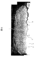
- Sectional photograph which shows an example of peeling and a crack between a cemented carbide part and a base material part.
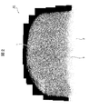
- An image figure showing a measurement result by EPMA of a cemented carbide composite material The image figure which shows the measurement result by EPMA of the cemented carbide composite material after heat processing.
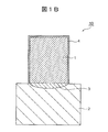
- FIG. 1A and FIG. 1B are schematic cross-sectional views showing an example of the cemented carbide composite material 10 according to the embodiment of the present invention.
- FIG. 2 is a cross-sectional photograph showing an example of the cemented carbide composite material 10 shown in FIG. 1A.
- the cemented carbide composite material 10 of the present embodiment is made of a WC-Co cemented carbide mainly composed of tungsten carbide (WC) and cobalt (Co) (containing 50 mass% or more in total of WC and Co). It has a cemented carbide portion 1 and a base portion 2 made of a metal containing 50% by mass or more in total of nickel (Ni) or Co.
- the cemented carbide composite material 10 has an intermediate layer 3 containing the component of the cemented carbide portion 1 and the component of the base portion 2 between the cemented carbide portion 1 and the base portion 2.
- the intermediate layer 3 includes a portion having a gamma phase fraction of 80% or more and a Vickers hardness of less than 700 HV.
- the WC—Co-based cemented carbide constituting the cemented carbide portion 1 is excellent in high temperature strength and wear resistance. Therefore, by providing the above-described configuration, the cemented carbide composite material 10 is excellent in high-temperature strength and can suppress the occurrence of cracking and peeling.
- the gamma phase is also called an austenite phase, and has a face-centered cubic (FCC) structure.
- the gamma phase fraction can be calculated from the area of the gamma phase occupied on the measurement screen by scanning a 200 ⁇ m ⁇ 200 ⁇ m range, for example, using the electron backscatter diffraction (EBSD) method. .
- EBSD electron backscatter diffraction
- Vickers hardness can be measured by a commercially available micro Vickers hardness tester.
- the cemented carbide composite material 10 has a coating layer 4 on the surface of the cemented carbide portion 1.
- the coating layer can be formed, for example, by nitriding the surface of the cemented carbide portion 1 or by chemical vapor deposition (CVD) or physical vapor deposition (PVD).
- the material of the coating layer 4 is not particularly limited.
- titanium carbide (TiC), titanium nitride (TiN), titanium carbonitride (TiCN), aluminum oxide (Al 2 O 3 ), titanium aluminum nitride (TiAlN), nitrided Chromium (CrN) or the like can be used.
- the cemented carbide composite material 10 has the coating layer 4 on the surface of the cemented carbide portion 1, the wear resistance of the cemented carbide portion 1 can be improved.
- the cemented carbide portion 1 is mainly made of WC—Co cemented carbide in which hard WC particles are dispersed in a metal phase having Co as a binder phase.
- the cemented carbide portion 1 as the amount of Co increases, the toughness improves. Therefore, as the amount of Co is larger, it is possible to suppress the occurrence of cracking or peeling during formation of the cemented carbide portion 1.
- the cemented carbide portion preferably has a Co content of 25% by mass or more and 50% by mass or less.
- the cemented carbide portion 1 of the cemented carbide composite material 10 can be prevented from cracking and peeling, and can have toughness, strength and hardness suitable for use as a tool, for example.
- the Vickers hardness of the cemented carbide portion 1 is preferably, for example, 400 HV or more and 1000 HV or less.
- the cemented carbide portion 1 can contain, for example, trace amounts of chromium (Cr), vanadium (V), titanium (Ti), tantalum (Ta), niobium (Nb). Cr and V can suppress the grain growth of WC particles and improve the oxidation resistance. Ti, Ta, Nb have the effect of expanding the healthy phase region of the cemented carbide structure. Also, the finer the WC particles, the better the strength and toughness. Therefore, it is desirable that the average particle diameter of the WC particles contained in the cemented carbide portion 1 be 50 ⁇ m or less.
- the average particle diameter of the WC particles contained in the cemented carbide portion 1 can be determined from the average value of the circle equivalent diameters of the particles on the test surface obtained by cutting the cemented carbide portion.
- the base portion 2 is made of a metal material mainly containing Ni or Co, or both, and a Ni-based alloy, a Co-based alloy, pure Ni, pure Co, a mixed alloy of Ni and Co, or another metal element for these as appropriate. And mixtures of nonmetallic elements other than metallic elements, and the like, and at least 50% by mass or more of at least one of Ni and Co, or 50% by mass or more of both in total. Depending on the composition and shape of the cemented carbide, peeling and cracking may occur at the time of modeling, and using pure Ni or pure Co as the base material portion 2 is desirable because defects caused by the added elements can be suppressed.
- the base portion 2 made of an alloy mainly contains Ni or Co, or both, and is a Ni-based alloy, a Co-based alloy, or a mixed alloy of Ni and Co.
- the Ni-based alloy includes, for example, 50% by mass or more of Ni, and additionally, chromium (Cr), cobalt (Co), molybdenum (Mo), tungsten (W), niobium (Nb), aluminum (Al), titanium (Ti) ), Iron (Fe), zirconium (Zr), tantalum (Ta), vanadium (V), hafnium (Hf), manganese (Mn), silicon (Si), lanthanum (La), magnesium (Mg), carbon (C) ), Boron (B) or the like, and is an alloy containing one or more elements.
- a Ni-based alloy is an alloy having a gamma phase as a main phase. Therefore, when the alloy portion is made of a Ni-based alloy, the gamma phase fraction of the intermediate layer becomes high, and a significant decrease in toughness can be suppressed.
- the composition of the alloy part is, for example, 8% by mass or more and 22% by mass or less of Cr, 28.5% by mass or less of Co, 14.5% by mass or less of Mo, W 12% by mass or less, Nb 5% by mass or less, Al 6.1% by mass or less, Ti 4.7% by mass or less, Fe 18.5% or less, Zr 0.1% by mass or less, Ta 4 Mass% or less, V is 1.0 mass% or less, Hf is 1.3 mass% or less, Mn is 0.05 mass% or more and 0.7 mass% or less, Si is 0.5 mass% or less, La is 0. 02 mass% or less, Mg is 0.02 mass% or less, C is 0.02 mass% or more and 0.2 mass% or less, B is 0.05 mass% or less, and the balance is Ni.
- a Co-based alloy is an alloy containing, for example, 50% by mass or more of Co, and additionally containing one or more elements selected from Cr, Ni, W, Mo, V, Fe, Mn, Si, C, etc.
- the same alloy as the binder phase of the cemented carbide portion 1 is an alloy containing Co as a main component.
- the alloy part is a Co-based alloy
- the composition of the alloy part is 30% by mass or less of Cr, 22% by mass or less of Ni, 15% by mass or less of W, 4.25% by mass or less of Mo, and V of 1.
- a mixed alloy of Ni and Co contains 50% by mass or more in total of Ni and Co, such as when a Co-based alloy and a Ni-based alloy are mixed (Ni-Co-based alloy), etc. , An alloy containing an additive element used for a Ni-based alloy.
- the restraining force of the cemented carbide part 1 by the alloyed part is weakened, the stress at the time of additive manufacturing is relaxed, and the occurrence of peeling can be suppressed.
- the cemented carbide composite 10 is used as a tool, for example, a certain degree of hardness is required. Therefore, the Vickers hardness of the alloy portion is preferably 200 HV or more and less than 500 HV. Thereby, the alloy portion 2 of the cemented carbide composite material 10 can be made to have a hardness suitable for use as a tool, for example.
- the intermediate layer 3 is a region which is formed between the cemented carbide portion 1 and the base portion 2 and contains the component of the cemented carbide portion 1 and the component of the base portion 2.
- the intermediate layer 3 is formed at the bonding interface between the cemented carbide portion 1 and the base portion 2 and in the vicinity thereof when the cemented carbide composite material 10 is manufactured.
- the intermediate layer 3 includes a portion having a gamma phase fraction of 80% or more and a Vickers hardness of less than 700 HV. As a result, the intermediate layer 3 can be obtained which has a low embrittlement phase due to martensitic transformation and the like and has a toughness that can withstand the thermal stress at the time of manufacturing the cemented carbide composite material 10.
- the Vickers hardness of the intermediate layer 3 is less than 700 HV, generation of cracks in the intermediate layer 3 can be suppressed at the time of manufacturing the cemented carbide composite material 10.
- the portion of 700 HV is preferably 20 vol% or more, more preferably 50 vol% or more, and still more preferably 80 vol% or more in the entire intermediate layer.
- the central portion of the intermediate layer 3 preferably has a gamma phase fraction of 80% or more and a Vickers hardness of less than 700 HV from the viewpoint of improvement in toughness and suppression of cracking.
- the central portion of the intermediate layer 3 more preferably has a gamma phase fraction of 90% or more and a Vickers hardness of less than 650 HV.
- the Vickers hardness of the central portion of the intermediate layer 3 is higher than the Vickers hardness of the base portion 2, that is, the Vickers hardness of the base portion 2 is the Vickers hardness of the central portion of the intermediate layer 3.
- the central portion of the intermediate layer 3 is, for example, a range of a circular region having a radius of 30% of the intermediate layer thickness from the center in the thickness direction of the intermediate layer 3.
- the intermediate layer 3 preferably has a small amount of M 6 C-type carbide in view of improvement in toughness.
- the presence of carbides of the M 6 C type can be determined, for example, by X-ray diffraction (XRD).
- the porosity fraction of the intermediate layer 3 is desirably 1% or less.
- the porosity fraction can be calculated, for example, by determining the area of the sample cross section through microscopic observation of the sample cross section and determining the area of the visible void.
- the presence of the intermediate layer 3 can be determined by appearance as shown in FIG.
- the boundary between the cemented carbide portion 1 and the intermediate layer 3 and the boundary between the base portion 2 and the intermediate layer 3 may not be clearly distinguished by observation with a microscope.
- the boundary between the cemented carbide portion 1 and the base portion 2 and the intermediate layer 3 can be defined by, for example, an electron probe micro analyzer (EPMA).
- EPMA electron probe micro analyzer
- the cemented carbide composite material 10 is cut so that the cemented carbide portion 1 and the base portion 2 can be observed in the same cross section. As shown in the example of FIG. 2, the cemented carbide portion 1 and the base portion 2 can be easily distinguished.
- line analysis is performed by EPMA, with the set value of the spot size being 0 ⁇ m, and the X-ray count number of tungsten is measured.
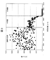
- FIG. 3 is a graph showing an example of the measurement result of the cemented carbide composite material 10 shown in FIG. 2 by EPMA.
- the horizontal axis is the measurement position [ ⁇ m] which is the distance from the measurement start point
- the vertical axis is the number of X-ray counts of tungsten.
- the boundary between the cemented carbide portion 1 and the intermediate layer 3 and the substantial boundary between the intermediate layer 3 and the base portion 2 can be defined, for example, by the fluctuation range of the X-ray count number of tungsten.
- the fluctuation range of the count number between analysis points adjacent to each other is about ⁇ 10%, while in the cemented carbide portion 1, between the analysis points adjacent to each other
- the fluctuation range of the count number is ⁇ 20% or more.
- the fluctuation range of count number and count number is very small.
- the intermediate layer contains the components of the cemented carbide portion and the base portion, it can be confirmed that the fluctuation range of the count number of W changes. Therefore, by measuring the X-ray count number of tungsten on the cut surface of the cemented carbide composite material 10 by EPMA, the boundary between the cemented carbide portion 1 and the mid layer 3 and the mid layer 3 and the base portion 2 Can substantially define the boundaries of
- the cemented carbide portion 1 of cemented carbide and the base of non-hardened alloy have higher high temperature strength than the conventional one and can suppress the occurrence of cracking and peeling.
- the cemented carbide composite material 10 provided with the material portion 2 can be provided.
- FIG. 4 is a flow diagram of a method S10 of producing a cemented carbide composite material according to an embodiment of the present invention.
- a method S10 of manufacturing a cemented carbide composite material according to the present embodiment includes a cemented carbide portion 1 made of the WC-Co cemented carbide as described above and a base portion made of a metal containing 50% by mass or more of Ni or Co in total.
- 2 is a method of manufacturing a cemented carbide composite material 10 having The method S10 of producing a cemented carbide composite material includes a preheating step S1 and a composite material manufacturing step S2.
- the embodiment of the present invention may include the heat treatment step S3.
- the preheating step S1 is a step of preheating the base portion 2 made of a metal containing 50 mass% or more of Ni or Co in total to a temperature of 350 ° C. or more.
- the preheating step S1 can be performed using, for example, high frequency induction heating, a gas burner, an infrared electric heater, a heating furnace, irradiation of an electron beam or a laser, or the like.
- the composite material manufacturing step S2 forms the cemented carbide portion 1 on the substrate portion 2 by addition and forms the component of the substrate portion 2 and cemented carbide between the substrate portion 2 and the cemented carbide portion 1
- the additive manufacturing method is not particularly limited, but for example, a directed energy deposition method such as laser metal deposition, a powder bed fusion bonding method, plasma powder buildup, etc. can be used.
- the material powder of WC-Co cemented carbide is melted using a heat source of laser, electron beam, plasma, or arc, and the melted material powder is used as the base 2
- the cemented carbide portion 1 is laminated and shaped.
- the cemented carbide portion 1 is formed on the base portion 2 by additional manufacturing, so that the cemented carbide portion 1 is formed at the interface between the cemented carbide portion 1 and the base portion 2 and in the vicinity thereof. Component of the base 2 and the component of the base portion 2 are mixed. Thereby, an intermediate layer 3 including the component of the cemented carbide portion 1 and the component of the substrate portion 2 is generated between the cemented carbide portion 1 and the substrate portion 2, and the cemented carbide portion 1 and the substrate portion are formed.
- a cemented carbide composite 10 is obtained having an intermediate layer 3 between the two.
- the substrate 2 is preheated to a predetermined temperature or higher in the preheating step S1 to reduce the cooling rate of the material melt-bonded at the time of the additional production of the cemented carbide portion 1 in the composite material manufacturing step S2. It is possible to suppress hardening and low temperature cracking of the cemented carbide portion 1 and diffusion of hydrogen.
- the temperature gradient of the cemented carbide portion 1 at the time of the additional manufacturing becomes gentle in the composite material manufacturing step S2, and the suppression of deformation by thermal stress and residual stress It becomes possible to ease. Further, by preheating the base material portion 2 to a temperature of 500 ° C. or more in the preheating step S1, the occurrence of micro cracks can be suppressed in the composite material manufacturing step S2.
- the heat treatment step S3 is a step of heat treating the cemented carbide composite material 10 at a temperature of 1000 ° C. or more and 1300 ° C. or less.
- the heat treatment step S3 can be performed in the manufacturing method of the present embodiment. preferable. Since the eta phase and free carbon are embrittled phases, their presence lowers the toughness of the cemented carbide portion 1.
- the toughness of the cemented carbide portion 1 is improved by diffusing and eliminating the eta phase and free carbon present in the cemented carbide portion 1 in the heat treatment step S3.
- the cemented carbide composite material 10 is formed in the heat treatment step S3. It is preferable to heat-process at the temperature of 1200 degreeC or more and 1300 degrees C or less.
- manufacturing method S10 of the cemented carbide composite material of this embodiment may have a cutting process of cutting the cemented carbide composite material 10 before and after the heat treatment process S3. Thereby, the shape accuracy of the cemented carbide composite material 10 can be further improved.
- FIG. 5 is a front view showing an example of the carbide tool 20 according to the embodiment of the present invention.
- the cemented carbide tool 20 is, for example, a punch of a warm forging die.
- the carbide tool 20 of the present embodiment is not limited to the warm forging die.
- the cemented carbide tool 20 can be used, for example, as a tool having in the processing portion 21 an operation surface that performs cutting, molding, movement, holding, and the like on a workpiece.
- the cemented carbide tool 20 is a tool using the cemented carbide composite material 10 described above.
- the cemented carbide tool 20 has a processing unit 21 for processing a workpiece and a base 22 for supporting the processing unit.
- the processed portion 21 of the cemented carbide tool 20 is the cemented carbide portion 1 of the cemented carbide composite material 10 described above, and the base 22 of the cemented carbide tool 20 is the base portion 2 of the cemented carbide composite material 10 described above. is there. That is, the cemented carbide tool 20 is manufactured by the above-described method S10 for manufacturing a cemented carbide composite material, and although not shown in FIG.
- the intermediate layer 3 is provided between the base portion 2 and the base portion 2.
- a conventional cemented carbide-based tool can be obtained, for example, by mixing and sintering WC particles and a Co-based alloy serving as a binder.
- Cemented carbides have high hardness and excellent wear resistance, but have poor toughness and deteriorate due to mechanical shock or thermal shock accompanying a heat history.
- An increase in the amount of Co in a Co-based alloy is effective for improving the toughness of the cemented carbide, but the problem is that the dimensional change during sintering is large.
- the cemented carbide tool 20 of the present embodiment can be manufactured by the method S10 of manufacturing a cemented carbide composite material using the additive manufacturing technology as described above. Therefore, near net shape shaping of the processing portion 21 having a complicated shape becomes possible, and shaping of a mold having an unprecedented function such as temperature control by a cooling water channel becomes possible.
- the processed portion 21 shaped by additive manufacturing has a higher density than conventional tools manufactured by sintering, and has an advantage that the dimensional change is small even if heat treatment is performed after shaping.
- the cemented carbide composite material 10 having the above-described configuration even if the processed portion 21 formed of the cemented carbide portion 1 is formed on the base portion 22 formed of the base portions 2 different in composition, processing is performed. It can suppress that peeling and a crack generate
- the bonding strength between the processed portion 21 formed of the cemented carbide portion 1 and the base portion 22 can be increased, and the toughness and hardness are good.
- the intermediate layer 3 can be formed.
- the gamma phase fraction of the substrate is preferably adjusted to 80% or more, more preferably 90% or more. Therefore, according to the present embodiment, it is possible to provide a crack-free cemented carbide tool 20 free from peeling or cracking between the processing portion 21 and the base portion 22. Therefore, according to the carbide tool 20, it is possible to further prolong the life as a tool used at high temperature such as warm hot forging.
- the raw material of cemented carbide is expensive, the cost of the raw material can be reduced by manufacturing the machined portion 21 where the tool acts on the workpiece from cemented carbide and configuring the other portions with different materials.
- No. 1 shown in Table 1 below. 1 to No. Alloys of three different compositions were prepared.
- the unit of composition shown in Table 1 is mass%, and "Bal" has shown "remainder.” That is, no. No. 1 is carbon steel; No. 2 is austenitic stainless steel; 3 is a Ni-based alloy.
- No. 1 is 140 [HV]
- no. 2 is 192 [HV]
- no. 3 was 307.5 [HV].
- the gamma phase fractions of the three prepared alloys were measured using EBSD method. No. 1 is 10% or less, No. 2 and No. 3 was confirmed to be 95% to 99%.
- Example 1 No. 1 shown in Table 1 as a base material part A preheating step of preheating this base portion to a temperature of 350 ° C. was performed using a Ni base alloy of No. 3. Next, a cemented carbide portion is formed on the substrate portion by addition manufacturing, and an intermediate layer containing a component of the substrate portion and a component of the cemented carbide portion is formed between the substrate portion and the cemented carbide portion. A composite material production process for producing a cemented carbide composite material was carried out. The additive manufacturing was performed by laser deposition of a directed energy deposition method using WC-Co cemented carbide powder having a Co content of 40% by mass as an additive manufacturing material.
- the material was attached so that the height was 10 mm with 8 passes per layer, and the layers were laminated over approximately 20 layers.
- Table 2 below shows the conditions for additive manufacturing. The additional manufacturing conditions shown in Table 2 were set such that the amount of heat input to the powder was relatively low so that cracking did not easily occur between the base portion and the cemented carbide portion.
- Example 2 A cemented carbide composite was manufactured in the same manner as in Example 1 described above, except that the temperature of the base portion in the preheating step was 500 ° C.
- Example 3 A cemented carbide composite was manufactured in the same manner as in Example 1 described above, except that the temperature of the base portion in the preheating step was 600 ° C.
- Example 5 A cemented carbide composite was manufactured in the same manner as in Example 1 except that the preheating step was omitted.
- FIG. 6 is a cross-sectional photograph showing an example of the separation S and the crack C between the cemented carbide portion 1 and the base portion 2 seen in Comparative Examples 1 to 5.
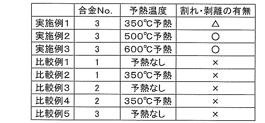
- the “presence or absence of cracking and peeling” shown in Table 3 is along the boundary between the cemented carbide portion 1 and the intermediate layer 3 or the boundary between the intermediate layer 3 and the base portion 2 among the cracks generated in the intermediate layer 3
- the lateral crack in the direction was S, and the other was crack C, and the determination was made as follows. Those with no cracks C and no peeling S were judged as "good”, those with no cracks S but no peeling S were judged as "good”, and cracks C and peeling S were found Were judged as "defective”.
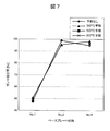
- FIG. 7 is a graph showing the gamma phase fraction in the intermediate layer 3 of the cemented carbide composite materials of Examples 1 to 3 and Comparative Examples 1 to 5.
- the horizontal axis in FIG. 7 represents the grade (alloy No) of the base plate (base material portion).
- the gamma phase fraction is measured in the range of 200 ⁇ m ⁇ 200 ⁇ m at a scan step of 0.7 ⁇ m in the central portion of the intermediate layer 3 of the cut surface of the cemented carbide composite material using the EBSD method, and occupies gamma on the measurement screen. Calculated from the area of the phase.
- the gamma phase fraction of Comparative Example 1 and Comparative Example 2 (Alloy No.
- Comparative Example 3 and Comparative Example 4 (Alloy No. 2) and Comparative Example 5 and Examples 1 to 3 in which cracking C and peeling S were relatively difficult to occur compared to Comparative Example 1 and Comparative Example 2
- the gamma phase fraction of (alloy No. 3) was 90% or more.
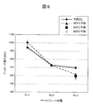
- FIG. 8 is a graph showing the results of the Vickers hardness test of the intermediate layer 3 of the cemented carbide composite materials of Examples 1 to 3 and Comparative Examples 1 to 5.
- the measurement of Vickers hardness used the test load of 500 gf, and holding time was 20 s using M type micro Vickers hardness tester by Shimadzu Corporation Corp. make.
- the measurement site was the central portion of the intermediate layer 3 of the cut surface of the composite (more specifically, the position moved to the cemented carbide portion side about 1 to 2 mm from the boundary between the base and the intermediate layer).
- the Vickers hardness of the intermediate layer 3 of Comparative Example 1 and Comparative Example 2 (alloy No. 1) showed a very high value of 900 or more.
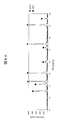
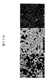
- FIGS. 9A to 9C show the XRD measurement result in the intermediate layer 3 of Example 1, Comparative Example 2 and Comparative Example 4.
- 9A, 9B and 9C show the measurement results in Example 1, Comparative Example 2 and Comparative Example 4, respectively.
- XRD uses a beam diameter of 100 ⁇ m, uses Cu as an X-ray source, an operation speed of 0.5 deg / min, sampling 0. It was measured as 01 deg.
- the peak of FCC was mainly detected, and in addition to the peak of FCC, the peak of WC was also detected.
- M 6 C type carbide is a cubic but has a complex crystal structure, and is an intermetallic compound which is more brittle than WC and lowers toughness. Therefore, it is desirable that the amount of carbides of the M 6 C type be small in the intermediate layer 3. Specifically, the area of the main peak of each crystal structure is determined by profile fitting, and the area of the main peak of the M 6 C-type carbide is preferably 2% or less with respect to the total of them.
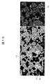
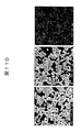
- FIG. 10 is an image diagram showing the results of measurement of the cemented carbide portion of the cemented carbide composite material of Example 2 by EPMA.
- WC particles 1 b having a particle diameter of several ⁇ m to about 20 ⁇ m can be confirmed in the matrix 1 a mainly made of Co.
- eta phase 1c which is a double carbide of W and Co, and free carbon 1d in which the C component is singly released. Since the eta phase 1c and the free carbon 1d act as an embrittlement phase, a structure formed only by the matrix phase 1a and the WC particles 1b is more desirable.
- the cemented carbide composite material of Example 2 was heat-treated at a temperature of 1200 ° C. to 1300 ° C.
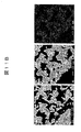
- the results of measuring the cemented carbide portion after heat treatment by EPMA are shown in FIGS. 11A to 11D.
- 11A, 11B, 11C, and 11D are the measurement results of the cemented carbide composite material heat-treated at temperatures of 1200 ° C., 1250 ° C., 1275 ° C., and 1300 ° C., respectively. It was confirmed that the eta phase 1c and the free carbon 1d disappeared in any of the samples. This improves the toughness of the cemented carbide portion.
- the toughening of the intermediate layer was examined. And as a result of repeating examination focusing on the combination of the cemented carbide portion and the base portion, by selecting the metal having a high gamma phase fraction for the base portion, the bonding strength with the cemented carbide portion is also high. It was confirmed that an intermediate layer having good toughness and hardness could be formed.
- the material in additive manufacturing where the material is melted, solidified and laminated on the base portion of a material different from the cemented carbide portion, the material is rapidly heated and cooled, so the thermal stress at the time of shaping is large and cracking occurs. It's easy to do.
- the cemented carbide portion has high strength and low toughness, the occurrence of peeling S is confirmed at the interface between the base material and the shaped object at the time of shaping. It was confirmed that exfoliation S is simultaneously melted at the time of laminating and forming the cemented carbide portion, and occurs in a region (intermediate layer 3) in which material components of the cemented carbide portion and the substrate portion are mixed.
Landscapes
- Chemical & Material Sciences (AREA)
- Engineering & Computer Science (AREA)
- Materials Engineering (AREA)
- Mechanical Engineering (AREA)
- Manufacturing & Machinery (AREA)
- Organic Chemistry (AREA)
- Metallurgy (AREA)
- Physics & Mathematics (AREA)
- Thermal Sciences (AREA)
- Crystallography & Structural Chemistry (AREA)
- Composite Materials (AREA)
- Automation & Control Theory (AREA)
- Powder Metallurgy (AREA)
- Cutting Tools, Boring Holders, And Turrets (AREA)
Abstract
Description
図1Aおよび図1Bは、本発明の実施の形態に係る超硬合金複合材10の一例を示す模式断面図である。図2は、図1Aに示す超硬合金複合材10の一例を示す断面写真図である。
一方、NiとCoとの混合合金は、Co基合金とNi基合金を混合した場合(Ni-Co基合金)等、NiとCoを合計で50質量%以上含み、その他に上述のCo基合金、Ni基合金に使用される添加元素を含む合金である。
図4は、本発明の実施の形態に係る超硬合金複合材の製造方法S10のフロー図である。本実施形態の超硬合金複合材の製造方法S10は、前述のWC-Co系超硬合金からなる超硬合金部1と、NiまたはCoを合計で50質量%以上含む金属よりなる基材部2とを有する超硬合金複合材10の製造方法である。超硬合金複合材の製造方法S10は、予熱工程S1と、複合材製作工程S2と、を含んでいる。ここで本発明の実施形態は、熱処理工程S3を含んでもよい。
次に、本発明の実施の形態に係る超硬工具について、図1Aから図4を援用し、図5を参照して説明する。図5は、本発明の実施の形態に係る超硬工具20の一例を示す正面図である。超硬工具20は、たとえば、温間鍛造金型のパンチである。なお、本実施形態の超硬工具20は、温間鍛造金型のパンチに限定されない。超硬工具20は、たとえば、被加工物に対して切削、成形、移動、保持などを行う作用面を加工部21に有する工具として用いることができる。
まず、基材部の素材として、以下の表1に示すNo.1からNo.3の3種の異なる組成の合金を用意した。表1に示す組成の単位は質量%であり、「Bal」は「残部」を示している。すなわち、No.1は、炭素鋼であり、No.2はオーステナイト系ステンレス鋼であり、No.3はNi基合金である。次に、用意した3種の合金のビッカース硬さを測定したところ、No.1は140[HV]、No.2は192[HV]、No.3は307.5[HV]であった。また、用意した3種の合金のガンマ相分率をEBSD法を用いて測定したところ、No.1は10%以下、No.2とNo.3は95%から99%であることを確認した。

基材部として表1に示すNo.3のNi基合金を用い、この基材部を350℃の温度に予熱する予熱工程を行った。次に、基材部の上に超硬合金部を付加製造によって造形し、基材部と超硬合金部との間に、基材部の成分と超硬合金部の成分を含む中間層を有する超硬合金複合材を製作する複合材製作工程を行った。付加製造は、付加製造材料としてCo量が40質量%であるWC―Co超硬合金粉末を用い、指向性エネルギー堆積方式のレーザデポジションにより行った。超硬合金部の造形は、1層あたり8パスで、高さが10mmになるように材料を付着させて、おおむね20層程度にわたって積層させた。以下の表2に、付加製造の条件を示す。表2に示す付加製造条件は、基材部と超硬合金部との間に割れが生じにくいよう、粉末への入熱量が比較的低くなるように設定した。

予熱工程における基材部の温度を500℃にした以外は、前述の実施例1と同様に超硬合金複合材を製作した。
予熱工程における基材部の温度を600℃にした以外は、前述の実施例1と同様に超硬合金複合材を製作した。
基材部として表1に示すNo.1の炭素鋼を用い、予熱工程を省略した以外は、前述の実施例1と同様に超硬合金複合材を製作した。
基材部として表1に示すNo.1の炭素鋼を用いた以外は、前述の実施例1と同様に超硬合金複合材を製作した。
基材部として表1に示すNo.2のオーステナイト系ステンレス鋼を用い、予熱工程を省略した以外は、前述の実施例1と同様に超硬合金複合材を製作した。
基材部として表1に示すNo.2のオーステナイト系ステンレス鋼を用いた以外は、前述の実施例1と同様に超硬合金複合材を製作した。
予熱工程を省略した以外は、前述の実施例1と同様に超硬合金複合材を製作した。
2 基材部
3 中間層
4 コーティング層
10 超硬合金複合材
20 超硬工具
21 加工部
22 基部
S1 予熱工程
S2 複合材製作工程
S3 熱処理工程
S10 超硬合金複合材の製造方法
Claims (15)
- WC-Co系超硬合金からなる超硬合金部と、NiおよびCoのうち少なくとも一方を合計で50質量%以上含む金属よりなる基材部とを有する超硬合金複合材であって、
前記超硬合金部と前記基材部との間に、前記超硬合金部の成分と前記基材部の成分を含む中間層を有し、
前記中間層は、ガンマ相分率が80%以上でビッカース硬さが700HV未満である部分を含むことを特徴とする超硬合金複合材。 - 前記基材部は、Ni、Co、Ni基合金、Co基合金、またはNiとCoとの混合合金よりなることを特徴とする請求項1に記載の超硬合金複合材。
- WC-Co系超硬合金からなる超硬合金部と、Ni基合金またはCo基合金からなる合金部とを有する超硬合金複合材であって、
前記超硬合金部と前記合金部との間に、前記超硬合金部の成分と前記合金部の成分を含む中間層を有し、
前記中間層は、ガンマ相分率が80%以上でビッカース硬さが700HV未満である部分を含むことを特徴とする超硬合金複合材。 - 前記超硬合金部は、Co量が25質量%以上、50質量%以下であることを特徴とする請求項1に記載の超硬合金複合材。
- 前記中間層の中心部は、ガンマ相分率が80%以上でビッカース硬さが700HV未満であり、
前記基材部のビッカース硬さは、前記中間層の前記中心部のビッカース硬さよりも低いことを特徴とする請求項1に記載の超硬合金複合材。 - 前記基材部のビッカース硬さは、200HV以上、500HV未満であることを特徴とする請求項5に記載の超硬合金複合材。
- 前記中間層の中心部は、ガンマ相分率が90%以上でビッカース硬さが650HV未満であることを特徴とする請求項1に記載の超硬合金複合材。
- 前記中間層をXRD測定した場合において、M6C型の炭化物のメインピークの面積が構成相全体の2%以下であることを特徴とする請求項1に記載の超硬合金複合材。
- 前記超硬合金部の表面にコーティング層を有することを特徴とする請求項1から請求項8のいずれか一項に記載の超硬合金複合材。
- WC-Co系超硬合金からなる超硬合金部と、NiおよびCoのうち少なくとも一方を合計で50質量%以上含む金属よりなる基材部とを有する超硬合金複合材の製造方法であって、
前記基材部を350℃以上の温度に予熱する予熱工程と、
前記基材部の上に前記超硬合金部を付加製造によって造形し、前記基材部と前記超硬合金部との間に、前記基材部の成分と前記超硬合金部の成分を含む中間層を有する超硬合金複合材を製作する複合材製作工程と、を含むことを特徴とする超硬合金複合材の製造方法。 - 前記基材部は、Ni、Co、Ni基合金、Co基合金、またはNiとCoとの混合合金よりなることを特徴とする請求項10に記載の超硬合金複合材の製造方法。
- 前記予熱工程において、前記基材部を500℃以上に予熱することを特徴とする請求項10に記載の超硬合金複合材の製造方法。
- 前記複合材製作工程の後に、前記超硬合金複合材を1000℃以上、1300℃以下の温度で熱処理する熱処理工程を含むことを特徴とする請求項10または請求項12に記載の超硬合金複合材の製造方法。
- 前記熱処理工程において、前記超硬合金複合材を1200℃以上、1300℃以下の温度で熱処理することを特徴とする請求項13に記載の超硬合金複合材の製造方法。
- 請求項1から請求項9のいずれか一項に記載の超硬合金複合材を用いた超硬工具であって、
ワークを加工する加工部と、該加工部を支持する基部とを有し、
前記加工部は前記超硬合金部であり、前記基部は前記基材部であることを特徴とする超硬工具。
Priority Applications (5)
| Application Number | Priority Date | Filing Date | Title |
|---|---|---|---|
| EP18864463.7A EP3705216A4 (en) | 2017-10-02 | 2018-09-20 | CARBIDE COMPOSITE MATERIAL, METHOD OF MANUFACTURING ITEM AND CARBIDE TOOL |
| JP2019546620A JP6977776B2 (ja) | 2017-10-02 | 2018-09-20 | 超硬合金複合材およびその製造方法ならびに超硬工具 |
| US16/651,614 US12539540B2 (en) | 2017-10-02 | 2018-09-20 | Cemented carbide composite material, method for producing same, and cemented carbide tool |
| CN201880061894.1A CN111132782B (zh) | 2017-10-02 | 2018-09-20 | 超硬合金复合材料及其制造方法以及超硬工具 |
| SG11202002823QA SG11202002823QA (en) | 2017-10-02 | 2018-09-20 | Cemented carbide composite material, method for producing same, and cemented carbide tool |
Applications Claiming Priority (2)
| Application Number | Priority Date | Filing Date | Title |
|---|---|---|---|
| JP2017-192951 | 2017-10-02 | ||
| JP2017192951 | 2017-10-02 |
Publications (1)
| Publication Number | Publication Date |
|---|---|
| WO2019069701A1 true WO2019069701A1 (ja) | 2019-04-11 |
Family
ID=65994345
Family Applications (1)
| Application Number | Title | Priority Date | Filing Date |
|---|---|---|---|
| PCT/JP2018/034850 Ceased WO2019069701A1 (ja) | 2017-10-02 | 2018-09-20 | 超硬合金複合材およびその製造方法ならびに超硬工具 |
Country Status (6)
| Country | Link |
|---|---|
| US (1) | US12539540B2 (ja) |
| EP (1) | EP3705216A4 (ja) |
| JP (1) | JP6977776B2 (ja) |
| CN (1) | CN111132782B (ja) |
| SG (1) | SG11202002823QA (ja) |
| WO (1) | WO2019069701A1 (ja) |
Cited By (8)
| Publication number | Priority date | Publication date | Assignee | Title |
|---|---|---|---|---|
| CN108441663A (zh) * | 2018-03-20 | 2018-08-24 | 昆山长鹰硬质合金有限公司 | 一种纳米晶硬质合金的热处理方法 |
| JP2020196109A (ja) * | 2019-06-04 | 2020-12-10 | 株式会社ジェイテクト | 歯切り工具及び歯切り工具の製造方法 |
| JP2021042403A (ja) * | 2019-09-06 | 2021-03-18 | 日立金属株式会社 | 複合部材および複合部材の製造方法 |
| JP2021188111A (ja) * | 2020-06-04 | 2021-12-13 | 株式会社ジェイテクト | 付加製造装置 |
| WO2022210221A1 (ja) * | 2021-03-30 | 2022-10-06 | 日立金属株式会社 | 複合部材、製造物および複合部材の製造方法 |
| WO2023037577A1 (ja) | 2021-09-10 | 2023-03-16 | 株式会社プロテリアル | サーメット複合材及びその製造方法、並びにサーメット工具 |
| WO2025143041A1 (ja) | 2023-12-28 | 2025-07-03 | Mmcリョウテック株式会社 | 硬質合金の被覆層および該硬質合金の被覆層を基材表面に有する機械物品 |
| WO2025143042A1 (ja) | 2023-12-28 | 2025-07-03 | Mmcリョウテック株式会社 | 被覆層の形成装置と形成方法 |
Citations (11)
| Publication number | Priority date | Publication date | Assignee | Title |
|---|---|---|---|---|
| JPH01221680A (ja) | 1988-02-29 | 1989-09-05 | Mitsui Petrochem Ind Ltd | 絶縁状態の検知方法 |
| JP2004211162A (ja) * | 2002-12-27 | 2004-07-29 | Jkb:Kk | プレス用金型の製造方法 |
| JP2006175456A (ja) * | 2004-12-21 | 2006-07-06 | Hitachi Metals Ltd | 超硬合金製圧延用複合ロール |
| JP2008169419A (ja) * | 2007-01-10 | 2008-07-24 | Yasushi Watanabe | 超硬複合化金属体およびその製造方法 |
| JP2011523681A (ja) * | 2008-06-02 | 2011-08-18 | ティーディーワイ・インダストリーズ・インコーポレーテッド | 超硬合金−金属合金複合体 |
| WO2012128708A1 (en) * | 2011-03-22 | 2012-09-27 | Diamorph Ab | Method of preparation of a metal/cemented carbide functionally graded material |
| JP2013107187A (ja) * | 2011-11-24 | 2013-06-06 | Mitsubishi Materials Corp | 表面被覆wc基超硬合金製切削工具 |
| JP2016108668A (ja) * | 2014-12-05 | 2016-06-20 | 株式会社日立製作所 | 複合部材および複合部材の製造方法 |
| JP2016196702A (ja) * | 2015-03-27 | 2016-11-24 | ゼネラル・エレクトリック・カンパニイ | 部品及びその製造方法 |
| US20160375493A1 (en) * | 2015-01-07 | 2016-12-29 | Kennametal Inc. | Methods of making sintered articles |
| JP2017501890A (ja) | 2014-11-20 | 2017-01-19 | ナム、ジョンウ | 超硬合金切削工具の製造方法及びこれによって製造された切削工具 |
Family Cites Families (8)
| Publication number | Priority date | Publication date | Assignee | Title |
|---|---|---|---|---|
| JP3633217B2 (ja) * | 1996-09-25 | 2005-03-30 | 松下電工株式会社 | 刃物及びその製造方法 |
| JP4039725B2 (ja) | 1998-02-09 | 2008-01-30 | 住友電工ハードメタル株式会社 | 超硬合金と鋼の接合材料およびその製造方法 |
| GB9927127D0 (en) * | 1999-11-16 | 2000-01-12 | Univ Warwick | A method of manufacturing an item and apparatus for manufacturing an item |
| WO2006064589A1 (ja) * | 2004-12-17 | 2006-06-22 | Hitachi Metals, Ltd. | モータ用回転子およびその製造方法 |
| CA2667323C (en) * | 2006-11-20 | 2012-10-30 | Kabushiki Kaisha Miyanaga | Hard tip and method for producing the same |
| US8163232B2 (en) * | 2008-10-28 | 2012-04-24 | University Of Utah Research Foundation | Method for making functionally graded cemented tungsten carbide with engineered hard surface |
| GB0823328D0 (en) * | 2008-12-22 | 2009-01-28 | Element Six Production Pty Ltd | Ultra hard/hard composite materials |
| CN106583726B (zh) * | 2017-01-24 | 2018-10-16 | 苏州大学 | 激光多光束熔覆装置 |
-
2018
- 2018-09-20 WO PCT/JP2018/034850 patent/WO2019069701A1/ja not_active Ceased
- 2018-09-20 CN CN201880061894.1A patent/CN111132782B/zh active Active
- 2018-09-20 JP JP2019546620A patent/JP6977776B2/ja active Active
- 2018-09-20 SG SG11202002823QA patent/SG11202002823QA/en unknown
- 2018-09-20 US US16/651,614 patent/US12539540B2/en active Active
- 2018-09-20 EP EP18864463.7A patent/EP3705216A4/en active Pending
Patent Citations (11)
| Publication number | Priority date | Publication date | Assignee | Title |
|---|---|---|---|---|
| JPH01221680A (ja) | 1988-02-29 | 1989-09-05 | Mitsui Petrochem Ind Ltd | 絶縁状態の検知方法 |
| JP2004211162A (ja) * | 2002-12-27 | 2004-07-29 | Jkb:Kk | プレス用金型の製造方法 |
| JP2006175456A (ja) * | 2004-12-21 | 2006-07-06 | Hitachi Metals Ltd | 超硬合金製圧延用複合ロール |
| JP2008169419A (ja) * | 2007-01-10 | 2008-07-24 | Yasushi Watanabe | 超硬複合化金属体およびその製造方法 |
| JP2011523681A (ja) * | 2008-06-02 | 2011-08-18 | ティーディーワイ・インダストリーズ・インコーポレーテッド | 超硬合金−金属合金複合体 |
| WO2012128708A1 (en) * | 2011-03-22 | 2012-09-27 | Diamorph Ab | Method of preparation of a metal/cemented carbide functionally graded material |
| JP2013107187A (ja) * | 2011-11-24 | 2013-06-06 | Mitsubishi Materials Corp | 表面被覆wc基超硬合金製切削工具 |
| JP2017501890A (ja) | 2014-11-20 | 2017-01-19 | ナム、ジョンウ | 超硬合金切削工具の製造方法及びこれによって製造された切削工具 |
| JP2016108668A (ja) * | 2014-12-05 | 2016-06-20 | 株式会社日立製作所 | 複合部材および複合部材の製造方法 |
| US20160375493A1 (en) * | 2015-01-07 | 2016-12-29 | Kennametal Inc. | Methods of making sintered articles |
| JP2016196702A (ja) * | 2015-03-27 | 2016-11-24 | ゼネラル・エレクトリック・カンパニイ | 部品及びその製造方法 |
Non-Patent Citations (1)
| Title |
|---|
| See also references of EP3705216A4 |
Cited By (15)
| Publication number | Priority date | Publication date | Assignee | Title |
|---|---|---|---|---|
| CN108441663A (zh) * | 2018-03-20 | 2018-08-24 | 昆山长鹰硬质合金有限公司 | 一种纳米晶硬质合金的热处理方法 |
| JP7451884B2 (ja) | 2019-06-04 | 2024-03-19 | 株式会社ジェイテクト | 歯切り工具及び歯切り工具の製造方法 |
| JP2020196109A (ja) * | 2019-06-04 | 2020-12-10 | 株式会社ジェイテクト | 歯切り工具及び歯切り工具の製造方法 |
| JP2021042403A (ja) * | 2019-09-06 | 2021-03-18 | 日立金属株式会社 | 複合部材および複合部材の製造方法 |
| JP7255430B2 (ja) | 2019-09-06 | 2023-04-11 | 株式会社プロテリアル | 複合部材の製造方法 |
| JP2021188111A (ja) * | 2020-06-04 | 2021-12-13 | 株式会社ジェイテクト | 付加製造装置 |
| US12194537B2 (en) | 2020-06-04 | 2025-01-14 | Jtekt Corporation | Additive manufacturing device |
| JP7600547B2 (ja) | 2020-06-04 | 2024-12-17 | 株式会社ジェイテクト | 付加製造装置 |
| US20240157440A1 (en) * | 2021-03-30 | 2024-05-16 | Proterial, Ltd. | Composite member, product, and method for producing composite member |
| WO2022210221A1 (ja) * | 2021-03-30 | 2022-10-06 | 日立金属株式会社 | 複合部材、製造物および複合部材の製造方法 |
| JPWO2023037577A1 (ja) * | 2021-09-10 | 2023-03-16 | ||
| WO2023037577A1 (ja) | 2021-09-10 | 2023-03-16 | 株式会社プロテリアル | サーメット複合材及びその製造方法、並びにサーメット工具 |
| JP7859443B2 (ja) | 2021-09-10 | 2026-05-15 | 株式会社プロテリアル | サーメット複合材及びその製造方法、並びにサーメット工具 |
| WO2025143041A1 (ja) | 2023-12-28 | 2025-07-03 | Mmcリョウテック株式会社 | 硬質合金の被覆層および該硬質合金の被覆層を基材表面に有する機械物品 |
| WO2025143042A1 (ja) | 2023-12-28 | 2025-07-03 | Mmcリョウテック株式会社 | 被覆層の形成装置と形成方法 |
Also Published As
| Publication number | Publication date |
|---|---|
| JP6977776B2 (ja) | 2021-12-08 |
| US12539540B2 (en) | 2026-02-03 |
| US20200299814A1 (en) | 2020-09-24 |
| CN111132782A (zh) | 2020-05-08 |
| EP3705216A4 (en) | 2021-09-15 |
| CN111132782B (zh) | 2022-07-19 |
| JPWO2019069701A1 (ja) | 2020-11-19 |
| SG11202002823QA (en) | 2020-04-29 |
| EP3705216A1 (en) | 2020-09-09 |
Similar Documents
| Publication | Publication Date | Title |
|---|---|---|
| JP6977776B2 (ja) | 超硬合金複合材およびその製造方法ならびに超硬工具 | |
| US10272497B2 (en) | Cladded articles and methods of making the same | |
| TWI457445B (zh) | Metal cermet | |
| EP2776204B1 (en) | Friction stir welding tool made of cemented tungsten carbid with nickel and with a al2o3 surface coating | |
| JP7255430B2 (ja) | 複合部材の製造方法 | |
| JP2018135585A (ja) | 金属部材及びクラッド層の製造方法 | |
| JP2012130948A (ja) | 回転ツール | |
| US20220134428A1 (en) | Method for manufacturing cobalt-based alloy structure, and cobalt-based alloy structure obtained thereby | |
| JP6178689B2 (ja) | タングステン耐熱合金、摩擦攪拌接合工具、および製造方法 | |
| JP7859443B2 (ja) | サーメット複合材及びその製造方法、並びにサーメット工具 | |
| EP4163409B1 (en) | Wear-resistant member | |
| Laansoo et al. | Induction brazing of cermets to steel | |
| JP7035820B2 (ja) | 基材および切削工具 | |
| JP6202787B2 (ja) | モリブデン耐熱合金、摩擦攪拌接合用工具、および製造方法 | |
| JP6578532B2 (ja) | 被覆層を有する耐熱合金製工具および加工装置 | |
| JP6208863B2 (ja) | タングステン耐熱合金、摩擦攪拌接合工具、および製造方法 | |
| JP2019171483A (ja) | 表面被覆切削工具 | |
| JP2019171482A (ja) | 表面被覆切削工具 | |
| JP2023064182A (ja) | 表面被覆切削工具 | |
| JP2017160539A (ja) | モリブデン耐熱合金、摩擦攪拌接合用工具、および製造方法 | |
| JP6039004B2 (ja) | 回転ツール | |
| JP2022098159A (ja) | 表面被覆切削工具 | |
| JP2019181592A (ja) | 切削工具 | |
| JP2017166071A (ja) | モリブデン耐熱合金、摩擦攪拌接合用工具、および製造方法 |
Legal Events
| Date | Code | Title | Description |
|---|---|---|---|
| 121 | Ep: the epo has been informed by wipo that ep was designated in this application |
Ref document number: 18864463 Country of ref document: EP Kind code of ref document: A1 |
|
| ENP | Entry into the national phase |
Ref document number: 2019546620 Country of ref document: JP Kind code of ref document: A |
|
| NENP | Non-entry into the national phase |
Ref country code: DE |
|
| ENP | Entry into the national phase |
Ref document number: 2018864463 Country of ref document: EP Effective date: 20200504 |
|
| WWG | Wipo information: grant in national office |
Ref document number: 16651614 Country of ref document: US |