WO2019065803A1 - 空隙層、積層体、空隙層の製造方法、光学部材および光学装置 - Google Patents
空隙層、積層体、空隙層の製造方法、光学部材および光学装置 Download PDFInfo
- Publication number
- WO2019065803A1 WO2019065803A1 PCT/JP2018/035846 JP2018035846W WO2019065803A1 WO 2019065803 A1 WO2019065803 A1 WO 2019065803A1 JP 2018035846 W JP2018035846 W JP 2018035846W WO 2019065803 A1 WO2019065803 A1 WO 2019065803A1
- Authority
- WO
- WIPO (PCT)
- Prior art keywords
- gel
- layer
- solvent
- void
- present
- Prior art date
Links
- 238000004519 manufacturing process Methods 0.000 title claims description 94
- 230000003287 optical effect Effects 0.000 title claims description 30
- 238000000034 method Methods 0.000 title description 77
- 239000002105 nanoparticle Substances 0.000 claims abstract description 45
- 150000001875 compounds Chemical class 0.000 claims abstract description 34
- 239000011800 void material Substances 0.000 claims description 281
- 239000007788 liquid Substances 0.000 claims description 114
- 238000000576 coating method Methods 0.000 claims description 100
- 239000011248 coating agent Substances 0.000 claims description 86
- 238000001035 drying Methods 0.000 claims description 70
- 230000015572 biosynthetic process Effects 0.000 claims description 40
- 125000003709 fluoroalkyl group Chemical group 0.000 claims description 20
- 239000006185 dispersion Substances 0.000 claims description 16
- 125000001153 fluoro group Chemical group F* 0.000 claims description 10
- 230000003232 mucoadhesive effect Effects 0.000 claims description 4
- 239000000853 adhesive Substances 0.000 abstract description 82
- 230000001070 adhesive effect Effects 0.000 abstract description 81
- 239000004820 Pressure-sensitive adhesive Substances 0.000 abstract description 80
- 239000010410 layer Substances 0.000 description 363
- 239000000499 gel Substances 0.000 description 265
- 239000002904 solvent Substances 0.000 description 236
- 239000010408 film Substances 0.000 description 112
- 239000002245 particle Substances 0.000 description 89
- KFZMGEQAYNKOFK-UHFFFAOYSA-N Isopropanol Chemical compound CC(C)O KFZMGEQAYNKOFK-UHFFFAOYSA-N 0.000 description 87
- 239000003054 catalyst Substances 0.000 description 86
- 239000000463 material Substances 0.000 description 83
- 150000003377 silicon compounds Chemical class 0.000 description 80
- 239000000047 product Substances 0.000 description 75
- 239000012790 adhesive layer Substances 0.000 description 70
- 238000000227 grinding Methods 0.000 description 66
- ZXEKIIBDNHEJCQ-UHFFFAOYSA-N isobutanol Chemical compound CC(C)CO ZXEKIIBDNHEJCQ-UHFFFAOYSA-N 0.000 description 52
- 239000000758 substrate Substances 0.000 description 52
- 239000000126 substance Substances 0.000 description 49
- 238000010438 heat treatment Methods 0.000 description 45
- 239000011148 porous material Substances 0.000 description 44
- 238000006467 substitution reaction Methods 0.000 description 39
- IAZDPXIOMUYVGZ-UHFFFAOYSA-N Dimethylsulphoxide Chemical compound CS(C)=O IAZDPXIOMUYVGZ-UHFFFAOYSA-N 0.000 description 36
- LFQSCWFLJHTTHZ-UHFFFAOYSA-N Ethanol Chemical compound CCO LFQSCWFLJHTTHZ-UHFFFAOYSA-N 0.000 description 36
- 239000000243 solution Substances 0.000 description 34
- 230000032683 aging Effects 0.000 description 32
- 229920001296 polysiloxane Polymers 0.000 description 31
- 238000009835 boiling Methods 0.000 description 29
- 238000001879 gelation Methods 0.000 description 27
- -1 polyethylene terephthalate Polymers 0.000 description 27
- 235000019441 ethanol Nutrition 0.000 description 26
- 229940035429 isobutyl alcohol Drugs 0.000 description 26
- XLYOFNOQVPJJNP-UHFFFAOYSA-N water Substances O XLYOFNOQVPJJNP-UHFFFAOYSA-N 0.000 description 26
- 239000002243 precursor Substances 0.000 description 25
- 230000008569 process Effects 0.000 description 25
- 238000004132 cross linking Methods 0.000 description 22
- 239000000203 mixture Substances 0.000 description 22
- 238000010298 pulverizing process Methods 0.000 description 22
- MUBZPKHOEPUJKR-UHFFFAOYSA-N Oxalic acid Chemical compound OC(=O)C(O)=O MUBZPKHOEPUJKR-UHFFFAOYSA-N 0.000 description 21
- NIXOWILDQLNWCW-UHFFFAOYSA-N acrylic acid group Chemical group C(C=C)(=O)O NIXOWILDQLNWCW-UHFFFAOYSA-N 0.000 description 21
- BTANRVKWQNVYAZ-UHFFFAOYSA-N butan-2-ol Chemical compound CCC(C)O BTANRVKWQNVYAZ-UHFFFAOYSA-N 0.000 description 21
- 125000000524 functional group Chemical group 0.000 description 21
- LRHPLDYGYMQRHN-UHFFFAOYSA-N N-Butanol Chemical compound CCCCO LRHPLDYGYMQRHN-UHFFFAOYSA-N 0.000 description 19
- 229920005989 resin Polymers 0.000 description 19
- 239000011347 resin Substances 0.000 description 19
- OKKJLVBELUTLKV-UHFFFAOYSA-N Methanol Chemical compound OC OKKJLVBELUTLKV-UHFFFAOYSA-N 0.000 description 18
- 125000000217 alkyl group Chemical group 0.000 description 18
- ZMXDDKWLCZADIW-UHFFFAOYSA-N Vilsmeier-Haack reagent Natural products CN(C)C=O ZMXDDKWLCZADIW-UHFFFAOYSA-N 0.000 description 17
- 125000005372 silanol group Chemical group 0.000 description 17
- XEKOWRVHYACXOJ-UHFFFAOYSA-N Ethyl acetate Chemical compound CCOC(C)=O XEKOWRVHYACXOJ-UHFFFAOYSA-N 0.000 description 15
- VYPSYNLAJGMNEJ-UHFFFAOYSA-N Silicium dioxide Chemical compound O=[Si]=O VYPSYNLAJGMNEJ-UHFFFAOYSA-N 0.000 description 15
- 125000004432 carbon atom Chemical group C* 0.000 description 15
- 238000006243 chemical reaction Methods 0.000 description 15
- 230000018044 dehydration Effects 0.000 description 15
- 238000006297 dehydration reaction Methods 0.000 description 15
- 230000000052 comparative effect Effects 0.000 description 14
- 238000012360 testing method Methods 0.000 description 14
- 238000006482 condensation reaction Methods 0.000 description 13
- 229920000139 polyethylene terephthalate Polymers 0.000 description 13
- 239000005020 polyethylene terephthalate Substances 0.000 description 13
- ZWEHNKRNPOVVGH-UHFFFAOYSA-N 2-Butanone Chemical compound CCC(C)=O ZWEHNKRNPOVVGH-UHFFFAOYSA-N 0.000 description 12
- IJGRMHOSHXDMSA-UHFFFAOYSA-N Atomic nitrogen Chemical compound N#N IJGRMHOSHXDMSA-UHFFFAOYSA-N 0.000 description 12
- AMQJEAYHLZJPGS-UHFFFAOYSA-N N-Pentanol Chemical compound CCCCCO AMQJEAYHLZJPGS-UHFFFAOYSA-N 0.000 description 12
- BLRPTPMANUNPDV-UHFFFAOYSA-N Silane Chemical compound [SiH4] BLRPTPMANUNPDV-UHFFFAOYSA-N 0.000 description 12
- VLKZOEOYAKHREP-UHFFFAOYSA-N n-Hexane Chemical compound CCCCCC VLKZOEOYAKHREP-UHFFFAOYSA-N 0.000 description 12
- 229910000077 silane Inorganic materials 0.000 description 12
- 238000002834 transmittance Methods 0.000 description 12
- 125000001931 aliphatic group Chemical group 0.000 description 11
- 239000002121 nanofiber Substances 0.000 description 11
- 238000003756 stirring Methods 0.000 description 11
- 239000000178 monomer Substances 0.000 description 10
- 238000002360 preparation method Methods 0.000 description 10
- 230000005070 ripening Effects 0.000 description 10
- QTBSBXVTEAMEQO-UHFFFAOYSA-N Acetic acid Chemical compound CC(O)=O QTBSBXVTEAMEQO-UHFFFAOYSA-N 0.000 description 9
- CSCPPACGZOOCGX-UHFFFAOYSA-N Acetone Chemical compound CC(C)=O CSCPPACGZOOCGX-UHFFFAOYSA-N 0.000 description 9
- NTIZESTWPVYFNL-UHFFFAOYSA-N Methyl isobutyl ketone Chemical compound CC(C)CC(C)=O NTIZESTWPVYFNL-UHFFFAOYSA-N 0.000 description 9
- UIHCLUNTQKBZGK-UHFFFAOYSA-N Methyl isobutyl ketone Natural products CCC(C)C(C)=O UIHCLUNTQKBZGK-UHFFFAOYSA-N 0.000 description 9
- KWYUFKZDYYNOTN-UHFFFAOYSA-M Potassium hydroxide Chemical compound [OH-].[K+] KWYUFKZDYYNOTN-UHFFFAOYSA-M 0.000 description 9
- HEMHJVSKTPXQMS-UHFFFAOYSA-M Sodium hydroxide Chemical compound [OH-].[Na+] HEMHJVSKTPXQMS-UHFFFAOYSA-M 0.000 description 9
- 238000009826 distribution Methods 0.000 description 9
- 239000006260 foam Substances 0.000 description 9
- 229920000058 polyacrylate Polymers 0.000 description 9
- ARXJGSRGQADJSQ-UHFFFAOYSA-N 1-methoxypropan-2-ol Chemical compound COCC(C)O ARXJGSRGQADJSQ-UHFFFAOYSA-N 0.000 description 8
- RTZKZFJDLAIYFH-UHFFFAOYSA-N Diethyl ether Chemical compound CCOCC RTZKZFJDLAIYFH-UHFFFAOYSA-N 0.000 description 8
- XUIMIQQOPSSXEZ-UHFFFAOYSA-N Silicon Chemical compound [Si] XUIMIQQOPSSXEZ-UHFFFAOYSA-N 0.000 description 8
- 239000002612 dispersion medium Substances 0.000 description 8
- 238000005259 measurement Methods 0.000 description 8
- 238000002156 mixing Methods 0.000 description 8
- 239000002994 raw material Substances 0.000 description 8
- 239000007787 solid Substances 0.000 description 8
- ZNQVEEAIQZEUHB-UHFFFAOYSA-N 2-ethoxyethanol Chemical compound CCOCCO ZNQVEEAIQZEUHB-UHFFFAOYSA-N 0.000 description 7
- VEXZGXHMUGYJMC-UHFFFAOYSA-N Hydrochloric acid Chemical compound Cl VEXZGXHMUGYJMC-UHFFFAOYSA-N 0.000 description 7
- 239000003795 chemical substances by application Substances 0.000 description 7
- 229910001873 dinitrogen Inorganic materials 0.000 description 7
- 235000006408 oxalic acid Nutrition 0.000 description 7
- 229920006395 saturated elastomer Polymers 0.000 description 7
- 239000000377 silicon dioxide Substances 0.000 description 7
- 230000001629 suppression Effects 0.000 description 7
- OZAIFHULBGXAKX-UHFFFAOYSA-N 2-(2-cyanopropan-2-yldiazenyl)-2-methylpropanenitrile Chemical compound N#CC(C)(C)N=NC(C)(C)C#N OZAIFHULBGXAKX-UHFFFAOYSA-N 0.000 description 6
- OMPJBNCRMGITSC-UHFFFAOYSA-N Benzoylperoxide Chemical compound C=1C=CC=CC=1C(=O)OOC(=O)C1=CC=CC=C1 OMPJBNCRMGITSC-UHFFFAOYSA-N 0.000 description 6
- YXFVVABEGXRONW-UHFFFAOYSA-N Toluene Chemical compound CC1=CC=CC=C1 YXFVVABEGXRONW-UHFFFAOYSA-N 0.000 description 6
- 239000000470 constituent Substances 0.000 description 6
- 238000011156 evaluation Methods 0.000 description 6
- 229910052731 fluorine Inorganic materials 0.000 description 6
- 239000011737 fluorine Substances 0.000 description 6
- 239000011521 glass Substances 0.000 description 6
- 238000007654 immersion Methods 0.000 description 6
- 125000005010 perfluoroalkyl group Chemical group 0.000 description 6
- 229910052710 silicon Inorganic materials 0.000 description 6
- XNWFRZJHXBZDAG-UHFFFAOYSA-N 2-METHOXYETHANOL Chemical compound COCCO XNWFRZJHXBZDAG-UHFFFAOYSA-N 0.000 description 5
- 238000005401 electroluminescence Methods 0.000 description 5
- 239000001257 hydrogen Substances 0.000 description 5
- 229910052739 hydrogen Inorganic materials 0.000 description 5
- 125000002887 hydroxy group Chemical group [H]O* 0.000 description 5
- 238000010030 laminating Methods 0.000 description 5
- 238000000691 measurement method Methods 0.000 description 5
- 230000007246 mechanism Effects 0.000 description 5
- 125000002496 methyl group Chemical group [H]C([H])([H])* 0.000 description 5
- 239000005543 nano-size silicon particle Substances 0.000 description 5
- 229920006267 polyester film Polymers 0.000 description 5
- 238000012545 processing Methods 0.000 description 5
- 238000001878 scanning electron micrograph Methods 0.000 description 5
- 239000010703 silicon Substances 0.000 description 5
- WEVYAHXRMPXWCK-UHFFFAOYSA-N Acetonitrile Chemical compound CC#N WEVYAHXRMPXWCK-UHFFFAOYSA-N 0.000 description 4
- VHUUQVKOLVNVRT-UHFFFAOYSA-N Ammonium hydroxide Chemical compound [NH4+].[OH-] VHUUQVKOLVNVRT-UHFFFAOYSA-N 0.000 description 4
- OKTJSMMVPCPJKN-UHFFFAOYSA-N Carbon Chemical compound [C] OKTJSMMVPCPJKN-UHFFFAOYSA-N 0.000 description 4
- 229920008347 Cellulose acetate propionate Polymers 0.000 description 4
- 229920002284 Cellulose triacetate Polymers 0.000 description 4
- 229920000089 Cyclic olefin copolymer Polymers 0.000 description 4
- FXHOOIRPVKKKFG-UHFFFAOYSA-N N,N-Dimethylacetamide Chemical compound CN(C)C(C)=O FXHOOIRPVKKKFG-UHFFFAOYSA-N 0.000 description 4
- IMNFDUFMRHMDMM-UHFFFAOYSA-N N-Heptane Chemical compound CCCCCCC IMNFDUFMRHMDMM-UHFFFAOYSA-N 0.000 description 4
- SECXISVLQFMRJM-UHFFFAOYSA-N N-Methylpyrrolidone Chemical compound CN1CCCC1=O SECXISVLQFMRJM-UHFFFAOYSA-N 0.000 description 4
- 239000004698 Polyethylene Substances 0.000 description 4
- 239000004743 Polypropylene Substances 0.000 description 4
- NNLVGZFZQQXQNW-ADJNRHBOSA-N [(2r,3r,4s,5r,6s)-4,5-diacetyloxy-3-[(2s,3r,4s,5r,6r)-3,4,5-triacetyloxy-6-(acetyloxymethyl)oxan-2-yl]oxy-6-[(2r,3r,4s,5r,6s)-4,5,6-triacetyloxy-2-(acetyloxymethyl)oxan-3-yl]oxyoxan-2-yl]methyl acetate Chemical compound O([C@@H]1O[C@@H]([C@H]([C@H](OC(C)=O)[C@H]1OC(C)=O)O[C@H]1[C@@H]([C@@H](OC(C)=O)[C@H](OC(C)=O)[C@@H](COC(C)=O)O1)OC(C)=O)COC(=O)C)[C@@H]1[C@@H](COC(C)=O)O[C@@H](OC(C)=O)[C@H](OC(C)=O)[C@H]1OC(C)=O NNLVGZFZQQXQNW-ADJNRHBOSA-N 0.000 description 4
- 239000003377 acid catalyst Substances 0.000 description 4
- 150000001298 alcohols Chemical class 0.000 description 4
- 125000003545 alkoxy group Chemical group 0.000 description 4
- 235000011114 ammonium hydroxide Nutrition 0.000 description 4
- 230000005540 biological transmission Effects 0.000 description 4
- 238000009833 condensation Methods 0.000 description 4
- 230000005494 condensation Effects 0.000 description 4
- 239000003431 cross linking reagent Substances 0.000 description 4
- 238000006460 hydrolysis reaction Methods 0.000 description 4
- 150000002576 ketones Chemical class 0.000 description 4
- 229910052757 nitrogen Inorganic materials 0.000 description 4
- 239000003960 organic solvent Substances 0.000 description 4
- 230000035515 penetration Effects 0.000 description 4
- JYVLIDXNZAXMDK-UHFFFAOYSA-N pentan-2-ol Chemical compound CCCC(C)O JYVLIDXNZAXMDK-UHFFFAOYSA-N 0.000 description 4
- 229920000573 polyethylene Polymers 0.000 description 4
- 229920001155 polypropylene Polymers 0.000 description 4
- 239000011164 primary particle Substances 0.000 description 4
- 229910001220 stainless steel Inorganic materials 0.000 description 4
- 239000010935 stainless steel Substances 0.000 description 4
- 238000003860 storage Methods 0.000 description 4
- 229920005992 thermoplastic resin Polymers 0.000 description 4
- IJROHELDTBDTPH-UHFFFAOYSA-N trimethoxy(3,3,4,4,5,5,6,6,6-nonafluorohexyl)silane Chemical compound CO[Si](OC)(OC)CCC(F)(F)C(F)(F)C(F)(F)C(F)(F)F IJROHELDTBDTPH-UHFFFAOYSA-N 0.000 description 4
- BPSIOYPQMFLKFR-UHFFFAOYSA-N trimethoxy-[3-(oxiran-2-ylmethoxy)propyl]silane Chemical compound CO[Si](OC)(OC)CCCOCC1CO1 BPSIOYPQMFLKFR-UHFFFAOYSA-N 0.000 description 4
- 238000004804 winding Methods 0.000 description 4
- SMZOUWXMTYCWNB-UHFFFAOYSA-N 2-(2-methoxy-5-methylphenyl)ethanamine Chemical compound COC1=CC=C(C)C=C1CCN SMZOUWXMTYCWNB-UHFFFAOYSA-N 0.000 description 3
- UHOVQNZJYSORNB-UHFFFAOYSA-N Benzene Chemical compound C1=CC=CC=C1 UHOVQNZJYSORNB-UHFFFAOYSA-N 0.000 description 3
- 239000004342 Benzoyl peroxide Substances 0.000 description 3
- UFHFLCQGNIYNRP-UHFFFAOYSA-N Hydrogen Chemical compound [H][H] UFHFLCQGNIYNRP-UHFFFAOYSA-N 0.000 description 3
- 150000001338 aliphatic hydrocarbons Chemical class 0.000 description 3
- 239000000908 ammonium hydroxide Substances 0.000 description 3
- 235000019400 benzoyl peroxide Nutrition 0.000 description 3
- CQEYYJKEWSMYFG-UHFFFAOYSA-N butyl acrylate Chemical compound CCCCOC(=O)C=C CQEYYJKEWSMYFG-UHFFFAOYSA-N 0.000 description 3
- 238000005520 cutting process Methods 0.000 description 3
- 230000006378 damage Effects 0.000 description 3
- 230000007547 defect Effects 0.000 description 3
- 238000006073 displacement reaction Methods 0.000 description 3
- 238000002296 dynamic light scattering Methods 0.000 description 3
- 125000004435 hydrogen atom Chemical group [H]* 0.000 description 3
- 230000007062 hydrolysis Effects 0.000 description 3
- 230000003301 hydrolyzing effect Effects 0.000 description 3
- PHTQWCKDNZKARW-UHFFFAOYSA-N isoamylol Chemical compound CC(C)CCO PHTQWCKDNZKARW-UHFFFAOYSA-N 0.000 description 3
- 239000012948 isocyanate Substances 0.000 description 3
- 150000002513 isocyanates Chemical class 0.000 description 3
- JMMWKPVZQRWMSS-UHFFFAOYSA-N isopropanol acetate Natural products CC(C)OC(C)=O JMMWKPVZQRWMSS-UHFFFAOYSA-N 0.000 description 3
- 229940011051 isopropyl acetate Drugs 0.000 description 3
- GWYFCOCPABKNJV-UHFFFAOYSA-M isovalerate Chemical compound CC(C)CC([O-])=O GWYFCOCPABKNJV-UHFFFAOYSA-M 0.000 description 3
- 238000007561 laser diffraction method Methods 0.000 description 3
- 239000004973 liquid crystal related substance Substances 0.000 description 3
- 230000014759 maintenance of location Effects 0.000 description 3
- 239000002609 medium Substances 0.000 description 3
- VNWKTOKETHGBQD-UHFFFAOYSA-N methane Chemical compound C VNWKTOKETHGBQD-UHFFFAOYSA-N 0.000 description 3
- GNARHXWTMJZNTP-UHFFFAOYSA-N methoxy-[3-(oxiran-2-ylmethoxy)propyl]silane Chemical compound CO[SiH2]CCCOCC1CO1 GNARHXWTMJZNTP-UHFFFAOYSA-N 0.000 description 3
- ZJBHFQKJEBGFNL-UHFFFAOYSA-N methylsilanetriol Chemical compound C[Si](O)(O)O ZJBHFQKJEBGFNL-UHFFFAOYSA-N 0.000 description 3
- 239000011259 mixed solution Substances 0.000 description 3
- 230000004048 modification Effects 0.000 description 3
- 238000012986 modification Methods 0.000 description 3
- QJGQUHMNIGDVPM-UHFFFAOYSA-N nitrogen group Chemical group [N] QJGQUHMNIGDVPM-UHFFFAOYSA-N 0.000 description 3
- 229920003023 plastic Polymers 0.000 description 3
- 239000004033 plastic Substances 0.000 description 3
- 239000003505 polymerization initiator Substances 0.000 description 3
- 238000006116 polymerization reaction Methods 0.000 description 3
- 229920002635 polyurethane Polymers 0.000 description 3
- 239000004814 polyurethane Substances 0.000 description 3
- 230000001681 protective effect Effects 0.000 description 3
- 238000001179 sorption measurement Methods 0.000 description 3
- 238000005507 spraying Methods 0.000 description 3
- 239000004094 surface-active agent Substances 0.000 description 3
- 239000000725 suspension Substances 0.000 description 3
- QPFMBZIOSGYJDE-UHFFFAOYSA-N 1,1,2,2-tetrachloroethane Chemical compound ClC(Cl)C(Cl)Cl QPFMBZIOSGYJDE-UHFFFAOYSA-N 0.000 description 2
- OMIGHNLMNHATMP-UHFFFAOYSA-N 2-hydroxyethyl prop-2-enoate Chemical compound OCCOC(=O)C=C OMIGHNLMNHATMP-UHFFFAOYSA-N 0.000 description 2
- QGZKDVFQNNGYKY-UHFFFAOYSA-N Ammonia Chemical compound N QGZKDVFQNNGYKY-UHFFFAOYSA-N 0.000 description 2
- 229920002799 BoPET Polymers 0.000 description 2
- 229920000049 Carbon (fiber) Polymers 0.000 description 2
- 102000004190 Enzymes Human genes 0.000 description 2
- 108090000790 Enzymes Proteins 0.000 description 2
- WHNWPMSKXPGLAX-UHFFFAOYSA-N N-Vinyl-2-pyrrolidone Chemical compound C=CN1CCCC1=O WHNWPMSKXPGLAX-UHFFFAOYSA-N 0.000 description 2
- CTQNGGLPUBDAKN-UHFFFAOYSA-N O-Xylene Chemical compound CC1=CC=CC=C1C CTQNGGLPUBDAKN-UHFFFAOYSA-N 0.000 description 2
- NQRYJNQNLNOLGT-UHFFFAOYSA-N Piperidine Chemical compound C1CCNCC1 NQRYJNQNLNOLGT-UHFFFAOYSA-N 0.000 description 2
- 206010040844 Skin exfoliation Diseases 0.000 description 2
- PPBRXRYQALVLMV-UHFFFAOYSA-N Styrene Chemical compound C=CC1=CC=CC=C1 PPBRXRYQALVLMV-UHFFFAOYSA-N 0.000 description 2
- QAOWNCQODCNURD-UHFFFAOYSA-N Sulfuric acid Chemical compound OS(O)(=O)=O QAOWNCQODCNURD-UHFFFAOYSA-N 0.000 description 2
- 239000002390 adhesive tape Substances 0.000 description 2
- 125000005370 alkoxysilyl group Chemical group 0.000 description 2
- PNEYBMLMFCGWSK-UHFFFAOYSA-N aluminium oxide Inorganic materials [O-2].[O-2].[O-2].[Al+3].[Al+3] PNEYBMLMFCGWSK-UHFFFAOYSA-N 0.000 description 2
- RDOXTESZEPMUJZ-UHFFFAOYSA-N anisole Chemical compound COC1=CC=CC=C1 RDOXTESZEPMUJZ-UHFFFAOYSA-N 0.000 description 2
- ZWDNVDDEDBXBMD-UHFFFAOYSA-N anthracen-9-ylmethyl n,n-diethylcarbamate Chemical compound C1=CC=C2C(COC(=O)N(CC)CC)=C(C=CC=C3)C3=CC2=C1 ZWDNVDDEDBXBMD-UHFFFAOYSA-N 0.000 description 2
- 239000003849 aromatic solvent Substances 0.000 description 2
- 239000007853 buffer solution Substances 0.000 description 2
- DKPFZGUDAPQIHT-UHFFFAOYSA-N butyl acetate Chemical compound CCCCOC(C)=O DKPFZGUDAPQIHT-UHFFFAOYSA-N 0.000 description 2
- 229910052799 carbon Inorganic materials 0.000 description 2
- 239000004917 carbon fiber Substances 0.000 description 2
- 239000002041 carbon nanotube Substances 0.000 description 2
- 229910021393 carbon nanotube Inorganic materials 0.000 description 2
- 230000003197 catalytic effect Effects 0.000 description 2
- 229920002678 cellulose Polymers 0.000 description 2
- 239000001913 cellulose Substances 0.000 description 2
- HKQOBOMRSSHSTC-UHFFFAOYSA-N cellulose acetate Chemical compound OC1C(O)C(O)C(CO)OC1OC1C(CO)OC(O)C(O)C1O.CC(=O)OCC1OC(OC(C)=O)C(OC(C)=O)C(OC(C)=O)C1OC1C(OC(C)=O)C(OC(C)=O)C(OC(C)=O)C(COC(C)=O)O1.CCC(=O)OCC1OC(OC(=O)CC)C(OC(=O)CC)C(OC(=O)CC)C1OC1C(OC(=O)CC)C(OC(=O)CC)C(OC(=O)CC)C(COC(=O)CC)O1 HKQOBOMRSSHSTC-UHFFFAOYSA-N 0.000 description 2
- 230000008859 change Effects 0.000 description 2
- MVPPADPHJFYWMZ-UHFFFAOYSA-N chlorobenzene Chemical compound ClC1=CC=CC=C1 MVPPADPHJFYWMZ-UHFFFAOYSA-N 0.000 description 2
- 230000001276 controlling effect Effects 0.000 description 2
- 238000007766 curtain coating Methods 0.000 description 2
- JHIVVAPYMSGYDF-UHFFFAOYSA-N cyclohexanone Chemical compound O=C1CCCCC1 JHIVVAPYMSGYDF-UHFFFAOYSA-N 0.000 description 2
- 238000000151 deposition Methods 0.000 description 2
- 230000008021 deposition Effects 0.000 description 2
- 238000011161 development Methods 0.000 description 2
- 230000018109 developmental process Effects 0.000 description 2
- 230000000694 effects Effects 0.000 description 2
- 239000003759 ester based solvent Substances 0.000 description 2
- 238000007765 extrusion coating Methods 0.000 description 2
- 238000005286 illumination Methods 0.000 description 2
- 239000003999 initiator Substances 0.000 description 2
- 239000010954 inorganic particle Substances 0.000 description 2
- 230000003993 interaction Effects 0.000 description 2
- MLFHJEHSLIIPHL-UHFFFAOYSA-N isoamyl acetate Chemical compound CC(C)CCOC(C)=O MLFHJEHSLIIPHL-UHFFFAOYSA-N 0.000 description 2
- BFXIKLCIZHOAAZ-UHFFFAOYSA-N methyltrimethoxysilane Chemical compound CO[Si](C)(OC)OC BFXIKLCIZHOAAZ-UHFFFAOYSA-N 0.000 description 2
- 239000012046 mixed solvent Substances 0.000 description 2
- 238000006011 modification reaction Methods 0.000 description 2
- TVMXDCGIABBOFY-UHFFFAOYSA-N octane Chemical compound CCCCCCCC TVMXDCGIABBOFY-UHFFFAOYSA-N 0.000 description 2
- 239000012788 optical film Substances 0.000 description 2
- 229960004624 perflexane Drugs 0.000 description 2
- ZJIJAJXFLBMLCK-UHFFFAOYSA-N perfluorohexane Chemical compound FC(F)(F)C(F)(F)C(F)(F)C(F)(F)C(F)(F)C(F)(F)F ZJIJAJXFLBMLCK-UHFFFAOYSA-N 0.000 description 2
- 239000012466 permeate Substances 0.000 description 2
- 230000001699 photocatalysis Effects 0.000 description 2
- 239000011941 photocatalyst Substances 0.000 description 2
- 239000011112 polyethylene naphthalate Substances 0.000 description 2
- 229920000642 polymer Polymers 0.000 description 2
- 230000001737 promoting effect Effects 0.000 description 2
- BDERNNFJNOPAEC-UHFFFAOYSA-N propan-1-ol Chemical compound CCCO BDERNNFJNOPAEC-UHFFFAOYSA-N 0.000 description 2
- 229940090181 propyl acetate Drugs 0.000 description 2
- 239000004065 semiconductor Substances 0.000 description 2
- 238000000935 solvent evaporation Methods 0.000 description 2
- 125000006850 spacer group Chemical group 0.000 description 2
- 230000035882 stress Effects 0.000 description 2
- 238000003786 synthesis reaction Methods 0.000 description 2
- VZGDMQKNWNREIO-UHFFFAOYSA-N tetrachloromethane Chemical compound ClC(Cl)(Cl)Cl VZGDMQKNWNREIO-UHFFFAOYSA-N 0.000 description 2
- 229920001187 thermosetting polymer Polymers 0.000 description 2
- YDLQKLWVKKFPII-UHFFFAOYSA-N timiperone Chemical compound C1=CC(F)=CC=C1C(=O)CCCN1CCC(N2C(NC3=CC=CC=C32)=S)CC1 YDLQKLWVKKFPII-UHFFFAOYSA-N 0.000 description 2
- 229950000809 timiperone Drugs 0.000 description 2
- DVKJHBMWWAPEIU-UHFFFAOYSA-N toluene 2,4-diisocyanate Chemical compound CC1=CC=C(N=C=O)C=C1N=C=O DVKJHBMWWAPEIU-UHFFFAOYSA-N 0.000 description 2
- 238000001291 vacuum drying Methods 0.000 description 2
- 239000003021 water soluble solvent Substances 0.000 description 2
- 239000011240 wet gel Substances 0.000 description 2
- 239000008096 xylene Substances 0.000 description 2
- QNODIIQQMGDSEF-UHFFFAOYSA-N (1-hydroxycyclohexyl)-phenylmethanone Chemical compound C=1C=CC=CC=1C(=O)C1(O)CCCCC1 QNODIIQQMGDSEF-UHFFFAOYSA-N 0.000 description 1
- VJDHKUHTYJLWPV-UHFFFAOYSA-N (2-nitrophenyl)methyl 4-(2-methylprop-2-enoyloxy)piperidine-1-carboxylate Chemical compound C(C(=C)C)(=O)OC1CCN(CC1)C(=O)OCC1=C(C=CC=C1)[N+](=O)[O-] VJDHKUHTYJLWPV-UHFFFAOYSA-N 0.000 description 1
- HFROTQKOFJESPY-CMDGGOBGSA-N (e)-3-(2-hydroxyphenyl)-1-piperidin-1-ylprop-2-en-1-one Chemical compound OC1=CC=CC=C1\C=C\C(=O)N1CCCCC1 HFROTQKOFJESPY-CMDGGOBGSA-N 0.000 description 1
- UOCLXMDMGBRAIB-UHFFFAOYSA-N 1,1,1-trichloroethane Chemical compound CC(Cl)(Cl)Cl UOCLXMDMGBRAIB-UHFFFAOYSA-N 0.000 description 1
- WSLDOOZREJYCGB-UHFFFAOYSA-N 1,2-Dichloroethane Chemical compound ClCCCl WSLDOOZREJYCGB-UHFFFAOYSA-N 0.000 description 1
- QWOVEJBDMKHZQK-UHFFFAOYSA-N 1,3,5-tris(3-trimethoxysilylpropyl)-1,3,5-triazinane-2,4,6-trione Chemical compound CO[Si](OC)(OC)CCCN1C(=O)N(CCC[Si](OC)(OC)OC)C(=O)N(CCC[Si](OC)(OC)OC)C1=O QWOVEJBDMKHZQK-UHFFFAOYSA-N 0.000 description 1
- RTTZISZSHSCFRH-UHFFFAOYSA-N 1,3-bis(isocyanatomethyl)benzene Chemical compound O=C=NCC1=CC=CC(CN=C=O)=C1 RTTZISZSHSCFRH-UHFFFAOYSA-N 0.000 description 1
- RYHBNJHYFVUHQT-UHFFFAOYSA-N 1,4-Dioxane Chemical compound C1COCCO1 RYHBNJHYFVUHQT-UHFFFAOYSA-N 0.000 description 1
- XLPJNCYCZORXHG-UHFFFAOYSA-N 1-morpholin-4-ylprop-2-en-1-one Chemical compound C=CC(=O)N1CCOCC1 XLPJNCYCZORXHG-UHFFFAOYSA-N 0.000 description 1
- KWVGIHKZDCUPEU-UHFFFAOYSA-N 2,2-dimethoxy-2-phenylacetophenone Chemical compound C=1C=CC=CC=1C(OC)(OC)C(=O)C1=CC=CC=C1 KWVGIHKZDCUPEU-UHFFFAOYSA-N 0.000 description 1
- JUCCZCZDAPBGIV-UHFFFAOYSA-N 2-(9-oxoxanthen-2-yl)propanoic acid Chemical compound C1=CC=C2C(=O)C3=CC(C(C(O)=O)C)=CC=C3OC2=C1 JUCCZCZDAPBGIV-UHFFFAOYSA-N 0.000 description 1
- GOXQRTZXKQZDDN-UHFFFAOYSA-N 2-Ethylhexyl acrylate Chemical compound CCCCC(CC)COC(=O)C=C GOXQRTZXKQZDDN-UHFFFAOYSA-N 0.000 description 1
- PTTPXKJBFFKCEK-UHFFFAOYSA-N 2-Methyl-4-heptanone Chemical compound CC(C)CC(=O)CC(C)C PTTPXKJBFFKCEK-UHFFFAOYSA-N 0.000 description 1
- QQZOPKMRPOGIEB-UHFFFAOYSA-N 2-Oxohexane Chemical compound CCCCC(C)=O QQZOPKMRPOGIEB-UHFFFAOYSA-N 0.000 description 1
- POAOYUHQDCAZBD-UHFFFAOYSA-N 2-butoxyethanol Chemical compound CCCCOCCO POAOYUHQDCAZBD-UHFFFAOYSA-N 0.000 description 1
- SVONRAPFKPVNKG-UHFFFAOYSA-N 2-ethoxyethyl acetate Chemical compound CCOCCOC(C)=O SVONRAPFKPVNKG-UHFFFAOYSA-N 0.000 description 1
- NJRHMGPRPPEGQL-UHFFFAOYSA-N 2-hydroxybutyl prop-2-enoate Chemical compound CCC(O)COC(=O)C=C NJRHMGPRPPEGQL-UHFFFAOYSA-N 0.000 description 1
- QTWJRLJHJPIABL-UHFFFAOYSA-N 2-methylphenol;3-methylphenol;4-methylphenol Chemical compound CC1=CC=C(O)C=C1.CC1=CC=CC(O)=C1.CC1=CC=CC=C1O QTWJRLJHJPIABL-UHFFFAOYSA-N 0.000 description 1
- RZVINYQDSSQUKO-UHFFFAOYSA-N 2-phenoxyethyl prop-2-enoate Chemical compound C=CC(=O)OCCOC1=CC=CC=C1 RZVINYQDSSQUKO-UHFFFAOYSA-N 0.000 description 1
- NDWUBGAGUCISDV-UHFFFAOYSA-N 4-hydroxybutyl prop-2-enoate Chemical compound OCCCCOC(=O)C=C NDWUBGAGUCISDV-UHFFFAOYSA-N 0.000 description 1
- MQWCXKGKQLNYQG-UHFFFAOYSA-N 4-methylcyclohexan-1-ol Chemical compound CC1CCC(O)CC1 MQWCXKGKQLNYQG-UHFFFAOYSA-N 0.000 description 1
- VGVHNLRUAMRIEW-UHFFFAOYSA-N 4-methylcyclohexan-1-one Chemical compound CC1CCC(=O)CC1 VGVHNLRUAMRIEW-UHFFFAOYSA-N 0.000 description 1
- FIHBHSQYSYVZQE-UHFFFAOYSA-N 6-prop-2-enoyloxyhexyl prop-2-enoate Chemical compound C=CC(=O)OCCCCCCOC(=O)C=C FIHBHSQYSYVZQE-UHFFFAOYSA-N 0.000 description 1
- CBFAZWAGKJUAAD-UHFFFAOYSA-N C(C)O[Si](OCC)(OCC)C(CC)(CC)[Si](OCC)(OCC)OCC Chemical compound C(C)O[Si](OCC)(OCC)C(CC)(CC)[Si](OCC)(OCC)OCC CBFAZWAGKJUAAD-UHFFFAOYSA-N 0.000 description 1
- CBMHHCNDXPVVKT-UHFFFAOYSA-N CO[Si](OC)(OC)C(CN)(N(CCC)CCCC)[Si](OC)(OC)OC Chemical compound CO[Si](OC)(OC)C(CN)(N(CCC)CCCC)[Si](OC)(OC)OC CBMHHCNDXPVVKT-UHFFFAOYSA-N 0.000 description 1
- 229920002101 Chitin Polymers 0.000 description 1
- 229920001661 Chitosan Polymers 0.000 description 1
- 241000284156 Clerodendrum quadriloculare Species 0.000 description 1
- XDTMQSROBMDMFD-UHFFFAOYSA-N Cyclohexane Chemical compound C1CCCCC1 XDTMQSROBMDMFD-UHFFFAOYSA-N 0.000 description 1
- OTMSDBZUPAUEDD-UHFFFAOYSA-N Ethane Chemical compound CC OTMSDBZUPAUEDD-UHFFFAOYSA-N 0.000 description 1
- SXRSQZLOMIGNAQ-UHFFFAOYSA-N Glutaraldehyde Chemical compound O=CCCCC=O SXRSQZLOMIGNAQ-UHFFFAOYSA-N 0.000 description 1
- 229920000877 Melamine resin Polymers 0.000 description 1
- CYTYCFOTNPOANT-UHFFFAOYSA-N Perchloroethylene Chemical group ClC(Cl)=C(Cl)Cl CYTYCFOTNPOANT-UHFFFAOYSA-N 0.000 description 1
- 239000006087 Silane Coupling Agent Substances 0.000 description 1
- GWEVSGVZZGPLCZ-UHFFFAOYSA-N Titan oxide Chemical compound O=[Ti]=O GWEVSGVZZGPLCZ-UHFFFAOYSA-N 0.000 description 1
- XSTXAVWGXDQKEL-UHFFFAOYSA-N Trichloroethylene Chemical group ClC=C(Cl)Cl XSTXAVWGXDQKEL-UHFFFAOYSA-N 0.000 description 1
- 238000000560 X-ray reflectometry Methods 0.000 description 1
- 238000005299 abrasion Methods 0.000 description 1
- 239000011358 absorbing material Substances 0.000 description 1
- 239000002253 acid Substances 0.000 description 1
- 230000002378 acidificating effect Effects 0.000 description 1
- 150000007513 acids Chemical class 0.000 description 1
- 239000003522 acrylic cement Substances 0.000 description 1
- 229920006397 acrylic thermoplastic Polymers 0.000 description 1
- 239000000654 additive Substances 0.000 description 1
- 238000004026 adhesive bonding Methods 0.000 description 1
- 239000002671 adjuvant Substances 0.000 description 1
- ZIXLDMFVRPABBX-UHFFFAOYSA-N alpha-methylcyclopentanone Natural products CC1CCCC1=O ZIXLDMFVRPABBX-UHFFFAOYSA-N 0.000 description 1
- 229910021529 ammonia Inorganic materials 0.000 description 1
- 239000007864 aqueous solution Substances 0.000 description 1
- QVGXLLKOCUKJST-UHFFFAOYSA-N atomic oxygen Chemical compound [O] QVGXLLKOCUKJST-UHFFFAOYSA-N 0.000 description 1
- 238000007611 bar coating method Methods 0.000 description 1
- 239000000440 bentonite Substances 0.000 description 1
- 229910000278 bentonite Inorganic materials 0.000 description 1
- SVPXDRXYRYOSEX-UHFFFAOYSA-N bentoquatam Chemical compound O.O=[Si]=O.O=[Al]O[Al]=O SVPXDRXYRYOSEX-UHFFFAOYSA-N 0.000 description 1
- 239000011942 biocatalyst Substances 0.000 description 1
- WTIYJTZALOEJQN-UHFFFAOYSA-N butan-1-ol 1,6-diisocyanatohexane Chemical compound CCCCO.O=C=NCCCCCCN=C=O WTIYJTZALOEJQN-UHFFFAOYSA-N 0.000 description 1
- 125000000484 butyl group Chemical group [H]C([*])([H])C([H])([H])C([H])([H])C([H])([H])[H] 0.000 description 1
- 239000002134 carbon nanofiber Substances 0.000 description 1
- 238000010382 chemical cross-linking Methods 0.000 description 1
- 239000007795 chemical reaction product Substances 0.000 description 1
- 239000011247 coating layer Substances 0.000 description 1
- 239000007859 condensation product Substances 0.000 description 1
- 238000010924 continuous production Methods 0.000 description 1
- 230000008602 contraction Effects 0.000 description 1
- 238000001816 cooling Methods 0.000 description 1
- 230000002596 correlated effect Effects 0.000 description 1
- 238000005336 cracking Methods 0.000 description 1
- 229930003836 cresol Natural products 0.000 description 1
- HPXRVTGHNJAIIH-UHFFFAOYSA-N cyclohexanol Chemical compound OC1CCCCC1 HPXRVTGHNJAIIH-UHFFFAOYSA-N 0.000 description 1
- BGTOWKSIORTVQH-UHFFFAOYSA-N cyclopentanone Chemical compound O=C1CCCC1 BGTOWKSIORTVQH-UHFFFAOYSA-N 0.000 description 1
- UURSXESKOOOTOV-UHFFFAOYSA-N dec-5-ene Chemical compound CCCCC=CCCCC UURSXESKOOOTOV-UHFFFAOYSA-N 0.000 description 1
- 238000000354 decomposition reaction Methods 0.000 description 1
- 230000006866 deterioration Effects 0.000 description 1
- 125000002147 dimethylamino group Chemical group [H]C([H])([H])N(*)C([H])([H])[H] 0.000 description 1
- 238000003618 dip coating Methods 0.000 description 1
- KPUWHANPEXNPJT-UHFFFAOYSA-N disiloxane Chemical group [SiH3]O[SiH3] KPUWHANPEXNPJT-UHFFFAOYSA-N 0.000 description 1
- 229920001971 elastomer Polymers 0.000 description 1
- 238000004945 emulsification Methods 0.000 description 1
- 150000002170 ethers Chemical class 0.000 description 1
- 125000001495 ethyl group Chemical group [H]C([H])([H])C([H])([H])* 0.000 description 1
- 238000001704 evaporation Methods 0.000 description 1
- 230000001747 exhibiting effect Effects 0.000 description 1
- 239000000835 fiber Substances 0.000 description 1
- 239000002657 fibrous material Substances 0.000 description 1
- 238000011049 filling Methods 0.000 description 1
- 239000007789 gas Substances 0.000 description 1
- 230000009477 glass transition Effects 0.000 description 1
- 238000007756 gravure coating Methods 0.000 description 1
- ZRALSGWEFCBTJO-UHFFFAOYSA-O guanidinium Chemical compound NC(N)=[NH2+] ZRALSGWEFCBTJO-UHFFFAOYSA-O 0.000 description 1
- 125000003187 heptyl group Chemical group [H]C([*])([H])C([H])([H])C([H])([H])C([H])([H])C([H])([H])C([H])([H])C([H])([H])[H] 0.000 description 1
- FUZZWVXGSFPDMH-UHFFFAOYSA-M hexanoate Chemical compound CCCCCC([O-])=O FUZZWVXGSFPDMH-UHFFFAOYSA-M 0.000 description 1
- 125000004051 hexyl group Chemical group [H]C([H])([H])C([H])([H])C([H])([H])C([H])([H])C([H])([H])C([H])([H])* 0.000 description 1
- 239000012456 homogeneous solution Substances 0.000 description 1
- 230000002209 hydrophobic effect Effects 0.000 description 1
- 125000004464 hydroxyphenyl group Chemical group 0.000 description 1
- 230000008595 infiltration Effects 0.000 description 1
- 238000001764 infiltration Methods 0.000 description 1
- 239000011810 insulating material Substances 0.000 description 1
- 230000010354 integration Effects 0.000 description 1
- 230000001678 irradiating effect Effects 0.000 description 1
- 230000001788 irregular Effects 0.000 description 1
- GJRQTCIYDGXPES-UHFFFAOYSA-N iso-butyl acetate Natural products CC(C)COC(C)=O GJRQTCIYDGXPES-UHFFFAOYSA-N 0.000 description 1
- 125000000959 isobutyl group Chemical group [H]C([H])([H])C([H])(C([H])([H])[H])C([H])([H])* 0.000 description 1
- FGKJLKRYENPLQH-UHFFFAOYSA-M isocaproate Chemical compound CC(C)CCC([O-])=O FGKJLKRYENPLQH-UHFFFAOYSA-M 0.000 description 1
- ZFSLODLOARCGLH-UHFFFAOYSA-N isocyanuric acid Chemical compound OC1=NC(O)=NC(O)=N1 ZFSLODLOARCGLH-UHFFFAOYSA-N 0.000 description 1
- 125000001449 isopropyl group Chemical group [H]C([H])([H])C([H])(*)C([H])([H])[H] 0.000 description 1
- OQAGVSWESNCJJT-UHFFFAOYSA-N isovaleric acid methyl ester Natural products COC(=O)CC(C)C OQAGVSWESNCJJT-UHFFFAOYSA-N 0.000 description 1
- 238000003475 lamination Methods 0.000 description 1
- 230000031700 light absorption Effects 0.000 description 1
- JDSHMPZPIAZGSV-UHFFFAOYSA-N melamine Chemical compound NC1=NC(N)=NC(N)=N1 JDSHMPZPIAZGSV-UHFFFAOYSA-N 0.000 description 1
- 125000000956 methoxy group Chemical group [H]C([H])([H])O* 0.000 description 1
- UZKWTJUDCOPSNM-UHFFFAOYSA-N methoxybenzene Substances CCCCOC=C UZKWTJUDCOPSNM-UHFFFAOYSA-N 0.000 description 1
- 125000000325 methylidene group Chemical group [H]C([H])=* 0.000 description 1
- YKYONYBAUNKHLG-UHFFFAOYSA-N n-Propyl acetate Natural products CCCOC(C)=O YKYONYBAUNKHLG-UHFFFAOYSA-N 0.000 description 1
- 239000012802 nanoclay Substances 0.000 description 1
- 239000001301 oxygen Substances 0.000 description 1
- 229910052760 oxygen Inorganic materials 0.000 description 1
- 125000001147 pentyl group Chemical group C(CCCC)* 0.000 description 1
- XBXHCBLBYQEYTI-UHFFFAOYSA-N piperidin-4-ylmethanol Chemical compound OCC1CCNCC1 XBXHCBLBYQEYTI-UHFFFAOYSA-N 0.000 description 1
- 229920003229 poly(methyl methacrylate) Polymers 0.000 description 1
- 229920000728 polyester Polymers 0.000 description 1
- 229920000570 polyether Polymers 0.000 description 1
- 229920002451 polyvinyl alcohol Polymers 0.000 description 1
- 238000007639 printing Methods 0.000 description 1
- 230000002250 progressing effect Effects 0.000 description 1
- 125000001436 propyl group Chemical group [H]C([*])([H])C([H])([H])C([H])([H])[H] 0.000 description 1
- 230000035484 reaction time Effects 0.000 description 1
- 230000001846 repelling effect Effects 0.000 description 1
- 238000011160 research Methods 0.000 description 1
- 239000013557 residual solvent Substances 0.000 description 1
- 238000006748 scratching Methods 0.000 description 1
- 230000002393 scratching effect Effects 0.000 description 1
- 238000004062 sedimentation Methods 0.000 description 1
- 150000004819 silanols Chemical class 0.000 description 1
- RMAQACBXLXPBSY-UHFFFAOYSA-N silicic acid Chemical compound O[Si](O)(O)O RMAQACBXLXPBSY-UHFFFAOYSA-N 0.000 description 1
- 239000002356 single layer Substances 0.000 description 1
- 238000005245 sintering Methods 0.000 description 1
- 229910052708 sodium Inorganic materials 0.000 description 1
- 239000011734 sodium Substances 0.000 description 1
- 238000004528 spin coating Methods 0.000 description 1
- 239000002344 surface layer Substances 0.000 description 1
- 238000009864 tensile test Methods 0.000 description 1
- ISXSCDLOGDJUNJ-UHFFFAOYSA-N tert-butyl prop-2-enoate Chemical compound CC(C)(C)OC(=O)C=C ISXSCDLOGDJUNJ-UHFFFAOYSA-N 0.000 description 1
- 238000010998 test method Methods 0.000 description 1
- 229950011008 tetrachloroethylene Drugs 0.000 description 1
- 229910052719 titanium Inorganic materials 0.000 description 1
- 239000010936 titanium Substances 0.000 description 1
- OGIDPMRJRNCKJF-UHFFFAOYSA-N titanium oxide Inorganic materials [Ti]=O OGIDPMRJRNCKJF-UHFFFAOYSA-N 0.000 description 1
- 238000012546 transfer Methods 0.000 description 1
- 125000005409 triarylsulfonium group Chemical group 0.000 description 1
- UBOXGVDOUJQMTN-UHFFFAOYSA-N trichloroethylene Natural products ClCC(Cl)Cl UBOXGVDOUJQMTN-UHFFFAOYSA-N 0.000 description 1
- FOQJQXVUMYLJSU-UHFFFAOYSA-N triethoxy(1-triethoxysilylethyl)silane Chemical compound CCO[Si](OCC)(OCC)C(C)[Si](OCC)(OCC)OCC FOQJQXVUMYLJSU-UHFFFAOYSA-N 0.000 description 1
- PGVSPORIGRCPMG-UHFFFAOYSA-N triethoxy(1-triethoxysilylhexyl)silane Chemical compound CCCCCC([Si](OCC)(OCC)OCC)[Si](OCC)(OCC)OCC PGVSPORIGRCPMG-UHFFFAOYSA-N 0.000 description 1
- LMEKMHPYJBYBEV-UHFFFAOYSA-N triethoxy(2-triethoxysilylpropan-2-yl)silane Chemical compound CCO[Si](OCC)(OCC)C(C)(C)[Si](OCC)(OCC)OCC LMEKMHPYJBYBEV-UHFFFAOYSA-N 0.000 description 1
- IDGYYGWFOFXISD-UHFFFAOYSA-N triethoxy(3-triethoxysilylbutan-2-yl)silane Chemical compound C(C)O[Si](OCC)(OCC)C(C)C(C)[Si](OCC)(OCC)OCC IDGYYGWFOFXISD-UHFFFAOYSA-N 0.000 description 1
- NIINUVYELHEORX-UHFFFAOYSA-N triethoxy(triethoxysilylmethyl)silane Chemical compound CCO[Si](OCC)(OCC)C[Si](OCC)(OCC)OCC NIINUVYELHEORX-UHFFFAOYSA-N 0.000 description 1
- 125000002023 trifluoromethyl group Chemical group FC(F)(F)* 0.000 description 1
- JCGDCINCKDQXDX-UHFFFAOYSA-N trimethoxy(2-trimethoxysilylethyl)silane Chemical compound CO[Si](OC)(OC)CC[Si](OC)(OC)OC JCGDCINCKDQXDX-UHFFFAOYSA-N 0.000 description 1
- QRTOPPGMVFGMNI-UHFFFAOYSA-N trimethoxy(3-trimethoxysilylbutan-2-yl)silane Chemical compound CO[Si](OC)(OC)C(C(C)[Si](OC)(OC)OC)C QRTOPPGMVFGMNI-UHFFFAOYSA-N 0.000 description 1
- BQXJQTRISSSESR-UHFFFAOYSA-N trimethoxy(3-trimethoxysilylpentan-3-yl)silane Chemical compound CO[Si](OC)(OC)C(CC)(CC)[Si](OC)(OC)OC BQXJQTRISSSESR-UHFFFAOYSA-N 0.000 description 1
- HQYALQRYBUJWDH-UHFFFAOYSA-N trimethoxy(propyl)silane Chemical compound CCC[Si](OC)(OC)OC HQYALQRYBUJWDH-UHFFFAOYSA-N 0.000 description 1
- DJYGUVIGOGFJOF-UHFFFAOYSA-N trimethoxy(trimethoxysilylmethyl)silane Chemical compound CO[Si](OC)(OC)C[Si](OC)(OC)OC DJYGUVIGOGFJOF-UHFFFAOYSA-N 0.000 description 1
- YUYCVXFAYWRXLS-UHFFFAOYSA-N trimethoxysilane Chemical compound CO[SiH](OC)OC YUYCVXFAYWRXLS-UHFFFAOYSA-N 0.000 description 1
- 238000009281 ultraviolet germicidal irradiation Methods 0.000 description 1
- NQPDZGIKBAWPEJ-UHFFFAOYSA-N valeric acid Chemical compound CCCCC(O)=O NQPDZGIKBAWPEJ-UHFFFAOYSA-N 0.000 description 1
- 229920002554 vinyl polymer Polymers 0.000 description 1
- 238000005303 weighing Methods 0.000 description 1
- 230000037303 wrinkles Effects 0.000 description 1
Images

Classifications
-
- C—CHEMISTRY; METALLURGY
- C08—ORGANIC MACROMOLECULAR COMPOUNDS; THEIR PREPARATION OR CHEMICAL WORKING-UP; COMPOSITIONS BASED THEREON
- C08J—WORKING-UP; GENERAL PROCESSES OF COMPOUNDING; AFTER-TREATMENT NOT COVERED BY SUBCLASSES C08B, C08C, C08F, C08G or C08H
- C08J9/00—Working-up of macromolecular substances to porous or cellular articles or materials; After-treatment thereof
- C08J9/0066—Use of inorganic compounding ingredients
- C08J9/0071—Nanosized fillers, i.e. having at least one dimension below 100 nanometers
- C08J9/008—Nanoparticles
-
- C—CHEMISTRY; METALLURGY
- C09—DYES; PAINTS; POLISHES; NATURAL RESINS; ADHESIVES; COMPOSITIONS NOT OTHERWISE PROVIDED FOR; APPLICATIONS OF MATERIALS NOT OTHERWISE PROVIDED FOR
- C09J—ADHESIVES; NON-MECHANICAL ASPECTS OF ADHESIVE PROCESSES IN GENERAL; ADHESIVE PROCESSES NOT PROVIDED FOR ELSEWHERE; USE OF MATERIALS AS ADHESIVES
- C09J7/00—Adhesives in the form of films or foils
- C09J7/20—Adhesives in the form of films or foils characterised by their carriers
-
- B—PERFORMING OPERATIONS; TRANSPORTING
- B05—SPRAYING OR ATOMISING IN GENERAL; APPLYING FLUENT MATERIALS TO SURFACES, IN GENERAL
- B05D—PROCESSES FOR APPLYING FLUENT MATERIALS TO SURFACES, IN GENERAL
- B05D7/00—Processes, other than flocking, specially adapted for applying liquids or other fluent materials to particular surfaces or for applying particular liquids or other fluent materials
- B05D7/24—Processes, other than flocking, specially adapted for applying liquids or other fluent materials to particular surfaces or for applying particular liquids or other fluent materials for applying particular liquids or other fluent materials
-
- B—PERFORMING OPERATIONS; TRANSPORTING
- B32—LAYERED PRODUCTS
- B32B—LAYERED PRODUCTS, i.e. PRODUCTS BUILT-UP OF STRATA OF FLAT OR NON-FLAT, e.g. CELLULAR OR HONEYCOMB, FORM
- B32B27/00—Layered products comprising a layer of synthetic resin
-
- B—PERFORMING OPERATIONS; TRANSPORTING
- B32—LAYERED PRODUCTS
- B32B—LAYERED PRODUCTS, i.e. PRODUCTS BUILT-UP OF STRATA OF FLAT OR NON-FLAT, e.g. CELLULAR OR HONEYCOMB, FORM
- B32B5/00—Layered products characterised by the non- homogeneity or physical structure, i.e. comprising a fibrous, filamentary, particulate or foam layer; Layered products characterised by having a layer differing constitutionally or physically in different parts
- B32B5/16—Layered products characterised by the non- homogeneity or physical structure, i.e. comprising a fibrous, filamentary, particulate or foam layer; Layered products characterised by having a layer differing constitutionally or physically in different parts characterised by features of a layer formed of particles, e.g. chips, powder or granules
-
- B—PERFORMING OPERATIONS; TRANSPORTING
- B32—LAYERED PRODUCTS
- B32B—LAYERED PRODUCTS, i.e. PRODUCTS BUILT-UP OF STRATA OF FLAT OR NON-FLAT, e.g. CELLULAR OR HONEYCOMB, FORM
- B32B5/00—Layered products characterised by the non- homogeneity or physical structure, i.e. comprising a fibrous, filamentary, particulate or foam layer; Layered products characterised by having a layer differing constitutionally or physically in different parts
- B32B5/18—Layered products characterised by the non- homogeneity or physical structure, i.e. comprising a fibrous, filamentary, particulate or foam layer; Layered products characterised by having a layer differing constitutionally or physically in different parts characterised by features of a layer of foamed material
-
- B—PERFORMING OPERATIONS; TRANSPORTING
- B32—LAYERED PRODUCTS
- B32B—LAYERED PRODUCTS, i.e. PRODUCTS BUILT-UP OF STRATA OF FLAT OR NON-FLAT, e.g. CELLULAR OR HONEYCOMB, FORM
- B32B5/00—Layered products characterised by the non- homogeneity or physical structure, i.e. comprising a fibrous, filamentary, particulate or foam layer; Layered products characterised by having a layer differing constitutionally or physically in different parts
- B32B5/22—Layered products characterised by the non- homogeneity or physical structure, i.e. comprising a fibrous, filamentary, particulate or foam layer; Layered products characterised by having a layer differing constitutionally or physically in different parts characterised by the presence of two or more layers which are next to each other and are fibrous, filamentary, formed of particles or foamed
- B32B5/30—Layered products characterised by the non- homogeneity or physical structure, i.e. comprising a fibrous, filamentary, particulate or foam layer; Layered products characterised by having a layer differing constitutionally or physically in different parts characterised by the presence of two or more layers which are next to each other and are fibrous, filamentary, formed of particles or foamed one layer being formed of particles, e.g. chips, granules, powder
-
- B—PERFORMING OPERATIONS; TRANSPORTING
- B32—LAYERED PRODUCTS
- B32B—LAYERED PRODUCTS, i.e. PRODUCTS BUILT-UP OF STRATA OF FLAT OR NON-FLAT, e.g. CELLULAR OR HONEYCOMB, FORM
- B32B7/00—Layered products characterised by the relation between layers; Layered products characterised by the relative orientation of features between layers, or by the relative values of a measurable parameter between layers, i.e. products comprising layers having different physical, chemical or physicochemical properties; Layered products characterised by the interconnection of layers
- B32B7/02—Physical, chemical or physicochemical properties
- B32B7/023—Optical properties
-
- B—PERFORMING OPERATIONS; TRANSPORTING
- B32—LAYERED PRODUCTS
- B32B—LAYERED PRODUCTS, i.e. PRODUCTS BUILT-UP OF STRATA OF FLAT OR NON-FLAT, e.g. CELLULAR OR HONEYCOMB, FORM
- B32B7/00—Layered products characterised by the relation between layers; Layered products characterised by the relative orientation of features between layers, or by the relative values of a measurable parameter between layers, i.e. products comprising layers having different physical, chemical or physicochemical properties; Layered products characterised by the interconnection of layers
- B32B7/04—Interconnection of layers
- B32B7/12—Interconnection of layers using interposed adhesives or interposed materials with bonding properties
- B32B7/14—Interconnection of layers using interposed adhesives or interposed materials with bonding properties applied in spaced arrangements, e.g. in stripes
-
- C—CHEMISTRY; METALLURGY
- C08—ORGANIC MACROMOLECULAR COMPOUNDS; THEIR PREPARATION OR CHEMICAL WORKING-UP; COMPOSITIONS BASED THEREON
- C08F—MACROMOLECULAR COMPOUNDS OBTAINED BY REACTIONS ONLY INVOLVING CARBON-TO-CARBON UNSATURATED BONDS
- C08F222/00—Copolymers of compounds having one or more unsaturated aliphatic radicals, each having only one carbon-to-carbon double bond, and at least one being terminated by a carboxyl radical and containing at least one other carboxyl radical in the molecule; Salts, anhydrides, esters, amides, imides, or nitriles thereof
- C08F222/10—Esters
- C08F222/12—Esters of phenols or saturated alcohols
-
- C—CHEMISTRY; METALLURGY
- C08—ORGANIC MACROMOLECULAR COMPOUNDS; THEIR PREPARATION OR CHEMICAL WORKING-UP; COMPOSITIONS BASED THEREON
- C08J—WORKING-UP; GENERAL PROCESSES OF COMPOUNDING; AFTER-TREATMENT NOT COVERED BY SUBCLASSES C08B, C08C, C08F, C08G or C08H
- C08J9/00—Working-up of macromolecular substances to porous or cellular articles or materials; After-treatment thereof
- C08J9/0014—Use of organic additives
- C08J9/0019—Use of organic additives halogenated
-
- C—CHEMISTRY; METALLURGY
- C08—ORGANIC MACROMOLECULAR COMPOUNDS; THEIR PREPARATION OR CHEMICAL WORKING-UP; COMPOSITIONS BASED THEREON
- C08J—WORKING-UP; GENERAL PROCESSES OF COMPOUNDING; AFTER-TREATMENT NOT COVERED BY SUBCLASSES C08B, C08C, C08F, C08G or C08H
- C08J9/00—Working-up of macromolecular substances to porous or cellular articles or materials; After-treatment thereof
- C08J9/0014—Use of organic additives
- C08J9/0042—Use of organic additives containing silicon
-
- C—CHEMISTRY; METALLURGY
- C08—ORGANIC MACROMOLECULAR COMPOUNDS; THEIR PREPARATION OR CHEMICAL WORKING-UP; COMPOSITIONS BASED THEREON
- C08J—WORKING-UP; GENERAL PROCESSES OF COMPOUNDING; AFTER-TREATMENT NOT COVERED BY SUBCLASSES C08B, C08C, C08F, C08G or C08H
- C08J9/00—Working-up of macromolecular substances to porous or cellular articles or materials; After-treatment thereof
- C08J9/009—Use of pretreated compounding ingredients
-
- C—CHEMISTRY; METALLURGY
- C08—ORGANIC MACROMOLECULAR COMPOUNDS; THEIR PREPARATION OR CHEMICAL WORKING-UP; COMPOSITIONS BASED THEREON
- C08K—Use of inorganic or non-macromolecular organic substances as compounding ingredients
- C08K9/00—Use of pretreated ingredients
- C08K9/04—Ingredients treated with organic substances
- C08K9/06—Ingredients treated with organic substances with silicon-containing compounds
-
- C—CHEMISTRY; METALLURGY
- C09—DYES; PAINTS; POLISHES; NATURAL RESINS; ADHESIVES; COMPOSITIONS NOT OTHERWISE PROVIDED FOR; APPLICATIONS OF MATERIALS NOT OTHERWISE PROVIDED FOR
- C09C—TREATMENT OF INORGANIC MATERIALS, OTHER THAN FIBROUS FILLERS, TO ENHANCE THEIR PIGMENTING OR FILLING PROPERTIES ; PREPARATION OF CARBON BLACK ; PREPARATION OF INORGANIC MATERIALS WHICH ARE NO SINGLE CHEMICAL COMPOUNDS AND WHICH ARE MAINLY USED AS PIGMENTS OR FILLERS
- C09C3/00—Treatment in general of inorganic materials, other than fibrous fillers, to enhance their pigmenting or filling properties
- C09C3/12—Treatment with organosilicon compounds
-
- C—CHEMISTRY; METALLURGY
- C09—DYES; PAINTS; POLISHES; NATURAL RESINS; ADHESIVES; COMPOSITIONS NOT OTHERWISE PROVIDED FOR; APPLICATIONS OF MATERIALS NOT OTHERWISE PROVIDED FOR
- C09D—COATING COMPOSITIONS, e.g. PAINTS, VARNISHES OR LACQUERS; FILLING PASTES; CHEMICAL PAINT OR INK REMOVERS; INKS; CORRECTING FLUIDS; WOODSTAINS; PASTES OR SOLIDS FOR COLOURING OR PRINTING; USE OF MATERIALS THEREFOR
- C09D201/00—Coating compositions based on unspecified macromolecular compounds
-
- C—CHEMISTRY; METALLURGY
- C09—DYES; PAINTS; POLISHES; NATURAL RESINS; ADHESIVES; COMPOSITIONS NOT OTHERWISE PROVIDED FOR; APPLICATIONS OF MATERIALS NOT OTHERWISE PROVIDED FOR
- C09D—COATING COMPOSITIONS, e.g. PAINTS, VARNISHES OR LACQUERS; FILLING PASTES; CHEMICAL PAINT OR INK REMOVERS; INKS; CORRECTING FLUIDS; WOODSTAINS; PASTES OR SOLIDS FOR COLOURING OR PRINTING; USE OF MATERIALS THEREFOR
- C09D5/00—Coating compositions, e.g. paints, varnishes or lacquers, characterised by their physical nature or the effects produced; Filling pastes
-
- C—CHEMISTRY; METALLURGY
- C09—DYES; PAINTS; POLISHES; NATURAL RESINS; ADHESIVES; COMPOSITIONS NOT OTHERWISE PROVIDED FOR; APPLICATIONS OF MATERIALS NOT OTHERWISE PROVIDED FOR
- C09D—COATING COMPOSITIONS, e.g. PAINTS, VARNISHES OR LACQUERS; FILLING PASTES; CHEMICAL PAINT OR INK REMOVERS; INKS; CORRECTING FLUIDS; WOODSTAINS; PASTES OR SOLIDS FOR COLOURING OR PRINTING; USE OF MATERIALS THEREFOR
- C09D7/00—Features of coating compositions, not provided for in group C09D5/00; Processes for incorporating ingredients in coating compositions
- C09D7/40—Additives
- C09D7/60—Additives non-macromolecular
- C09D7/61—Additives non-macromolecular inorganic
- C09D7/62—Additives non-macromolecular inorganic modified by treatment with other compounds
-
- C—CHEMISTRY; METALLURGY
- C09—DYES; PAINTS; POLISHES; NATURAL RESINS; ADHESIVES; COMPOSITIONS NOT OTHERWISE PROVIDED FOR; APPLICATIONS OF MATERIALS NOT OTHERWISE PROVIDED FOR
- C09J—ADHESIVES; NON-MECHANICAL ASPECTS OF ADHESIVE PROCESSES IN GENERAL; ADHESIVE PROCESSES NOT PROVIDED FOR ELSEWHERE; USE OF MATERIALS AS ADHESIVES
- C09J7/00—Adhesives in the form of films or foils
- C09J7/30—Adhesives in the form of films or foils characterised by the adhesive composition
- C09J7/38—Pressure-sensitive adhesives [PSA]
- C09J7/381—Pressure-sensitive adhesives [PSA] based on macromolecular compounds obtained by reactions involving only carbon-to-carbon unsaturated bonds
- C09J7/385—Acrylic polymers
-
- G—PHYSICS
- G02—OPTICS
- G02B—OPTICAL ELEMENTS, SYSTEMS OR APPARATUS
- G02B5/00—Optical elements other than lenses
- G02B5/02—Diffusing elements; Afocal elements
- G02B5/0268—Diffusing elements; Afocal elements characterized by the fabrication or manufacturing method
-
- G—PHYSICS
- G02—OPTICS
- G02B—OPTICAL ELEMENTS, SYSTEMS OR APPARATUS
- G02B5/00—Optical elements other than lenses
- G02B5/02—Diffusing elements; Afocal elements
- G02B5/0273—Diffusing elements; Afocal elements characterized by the use
- G02B5/0284—Diffusing elements; Afocal elements characterized by the use used in reflection
-
- C—CHEMISTRY; METALLURGY
- C09—DYES; PAINTS; POLISHES; NATURAL RESINS; ADHESIVES; COMPOSITIONS NOT OTHERWISE PROVIDED FOR; APPLICATIONS OF MATERIALS NOT OTHERWISE PROVIDED FOR
- C09J—ADHESIVES; NON-MECHANICAL ASPECTS OF ADHESIVE PROCESSES IN GENERAL; ADHESIVE PROCESSES NOT PROVIDED FOR ELSEWHERE; USE OF MATERIALS AS ADHESIVES
- C09J2400/00—Presence of inorganic and organic materials
- C09J2400/20—Presence of organic materials
- C09J2400/24—Presence of a foam
- C09J2400/243—Presence of a foam in the substrate
-
- C—CHEMISTRY; METALLURGY
- C09—DYES; PAINTS; POLISHES; NATURAL RESINS; ADHESIVES; COMPOSITIONS NOT OTHERWISE PROVIDED FOR; APPLICATIONS OF MATERIALS NOT OTHERWISE PROVIDED FOR
- C09J—ADHESIVES; NON-MECHANICAL ASPECTS OF ADHESIVE PROCESSES IN GENERAL; ADHESIVE PROCESSES NOT PROVIDED FOR ELSEWHERE; USE OF MATERIALS AS ADHESIVES
- C09J2433/00—Presence of (meth)acrylic polymer
-
- G—PHYSICS
- G02—OPTICS
- G02B—OPTICAL ELEMENTS, SYSTEMS OR APPARATUS
- G02B2207/00—Coding scheme for general features or characteristics of optical elements and systems of subclass G02B, but not including elements and systems which would be classified in G02B6/00 and subgroups
- G02B2207/101—Nanooptics
-
- G—PHYSICS
- G02—OPTICS
- G02B—OPTICAL ELEMENTS, SYSTEMS OR APPARATUS
- G02B2207/00—Coding scheme for general features or characteristics of optical elements and systems of subclass G02B, but not including elements and systems which would be classified in G02B6/00 and subgroups
- G02B2207/107—Porous materials, e.g. for reducing the refractive index
-
- G—PHYSICS
- G02—OPTICS
- G02B—OPTICAL ELEMENTS, SYSTEMS OR APPARATUS
- G02B5/00—Optical elements other than lenses
- G02B5/02—Diffusing elements; Afocal elements
Definitions
- the present invention relates to an air gap layer, a laminate, a method of manufacturing the air gap layer, an optical member, and an optical device.
- an air layer having a low refractive index is used as a total reflection layer.
- optical film members for example, a light guide plate and a reflection plate
- a liquid crystal device are stacked via an air layer.
- problems such as deflection of the members may occur, particularly when the members are large.
- integration of each member is desired. For this reason, it is carried out to unify each member with an adhesive agent, without intervening an air layer (for example, patent document 1).
- an air layer playing a role of total reflection disappears, optical characteristics such as light leakage may be deteriorated.
- Patent Document 2 describes a structure in which a layer having a lower refractive index than the light guide plate is inserted between the light guide plate and the reflection plate.
- a void layer having a void is used in order to set the refractive index to a low refractive index as close to air as possible.
- the void layer is used, for example, by being laminated with another layer via an adhesive layer.
- the pressure-sensitive adhesive or the adhesive constituting the adhesive layer penetrates into the voids of the void layer to fill the voids, and the porosity is reduced. It may decrease. The higher the porosity of the void layer, the easier the pressure-sensitive adhesive or adhesive penetrates.
- the molecular motion of the pressure sensitive adhesive or the adhesive makes it easy for the pressure sensitive adhesive or the adhesive to penetrate into the void.
- the pressure-sensitive adhesive or the adhesive In order to suppress or prevent the permeation of the pressure-sensitive adhesive or the adhesive into the void, it is preferable to use one having a high elastic modulus (hard) as the pressure-sensitive adhesive or the adhesive. However, if the elastic modulus of the pressure-sensitive adhesive or adhesive is high (hard), the adhesion or adhesion may be reduced. On the contrary, when the elastic modulus of the pressure-sensitive adhesive or adhesive is low (soft), high adhesion or adhesiveness is easily obtained, but the pressure-sensitive adhesive or adhesive may easily penetrate into the voids.
- a layer capable of suppressing the penetration of the pressure-sensitive adhesive or the adhesive (permeation suppression layer) on the void layer is used. It is also contemplated to use materials other than agents or adhesives. However, in this case, the step of forming the permeation suppression layer is required separately from the step of forming the void layer, which leads to an increase in the number of manufacturing steps.
- this invention aims at provision of the space
- the void layer of the present invention is characterized by including nanoparticles surface-modified with a compound having surface orientation, and having a porosity of 35% by volume or more.
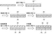
- the laminate of the present invention is a laminate in which the void layer of the present invention and the tacky-adhesive layer are directly laminated.
- the method for producing the void layer according to the present invention comprises the step of applying the dispersion containing the nanoparticles, and the step of drying the applied dispersion, the step of producing the void layer according to the present invention. It is a method.
- the optical member of the present invention is an optical member including the laminate of the present invention.
- the optical device of the present invention is an optical device including the optical member of the present invention.
- a void layer it is possible to provide a void layer, a laminate, a method of manufacturing the void layer, an optical member and an optical device, in which the adhesive or the adhesive does not easily penetrate into the void.
- FIG. 1 is process sectional drawing which shows typically an example of the method of forming the laminated body of this invention which laminated
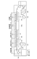
- FIG. 2 is a figure which shows typically a part of process in the manufacturing method of laminated film (laminated film roll) which is roll shape, and an example of an apparatus used therewith.
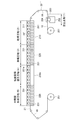
- FIG. 3 is a figure which shows typically a part of process in the manufacturing method of a lamination film roll, and another example of the apparatus used for it.
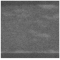
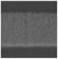
- FIG. 4 is a cross-sectional photograph of the laminate produced in Example 1.
- FIG. 5 is a cross-sectional photograph of the laminate produced in Comparative Example 1.
- FIG. 6 is a cross-sectional photograph of the laminate produced in Comparative Example 2.
- the compound having surface orientation is an alkoxysilane derivative
- the alkoxysilane derivative contains a fluoroalkyl group having 5 to 17 or 5 to 10 fluorine atoms. It is also good.
- the fluoroalkyl group may be an alkyl group in which only a part of hydrogen is substituted by fluorine, or may be an alkyl group in which all hydrogens are substituted by fluorine (perfluoroalkyl group).
- the void layer of the present invention may contain, for example, 10 to 50% by mass of the nanoparticles with respect to the skeleton component of the void layer.
- a layer composed of the nanoparticles may be formed inside the void layer together with the formation of the void layer.
- the adhesive or the adhesive does not easily penetrate into the void. For this reason, formation of another permeation suppression layer is unnecessary, and it is possible to directly laminate the void layer of the present invention and the pressure-sensitive adhesive layer. Therefore, the increase in the manufacturing process by the formation process of the said permeation suppression layer can be avoided.
- the reason (mechanism) in which the adhesive or the adhesive does not easily penetrate into the voids in the void layer of the present invention is considered as follows, for example.
- surface orientation is imparted to the surface-modified nanoparticles themselves using the surface orientation (transferability to the air interface) of a compound having surface orientation (for example, a compound having perfluoroalkyl) Do.
- a compound having surface orientation for example, a compound having perfluoroalkyl
- the surface modification of the void layer can be performed only with the compound having surface orientation, it is insufficient to suppress the penetration of the macro pressure-sensitive adhesive. Therefore, the voids on the outermost surface of the void layer are filled with the nanoparticles to physically suppress the permeation of the pressure-sensitive adhesive or the adhesive.
- nanoparticles having no surface modification do not have surface orientation, they are not oriented on the surface of the void layer only by being present in the void layer and do not exhibit a permeation suppression effect.
- the nanoparticles By modifying the nanoparticles with a compound having surface orientation, the nanoparticles have surface orientation to the void layer.
- the nanoparticles fill the voids on the outermost surface of the void layer to physically suppress the permeation of the pressure-sensitive adhesive or the adhesive. That is, when the nanoparticles modified with the compound having surface orientation are filled in the voids on the outermost surface of the void layer, the permeation suppression layer of the pressure-sensitive adhesive or the adhesive is formed on the outermost surface (surface layer).
- nanoparticles modified with a compound having surface orientation may be added to the coating liquid for void layer formation.
- the void layer of the present invention contains nanoparticles surface-modified with a compound having surface orientation, and the porosity is 35% by volume or more. Further, in the laminate of the present invention, as described above, the void layer of the present invention and the tacky-adhesive layer are directly laminated.
- the pressure-sensitive adhesive layer may be laminated on one side of the void layer of the present invention, or may be laminated on both sides.
- the pressure-sensitive adhesive layer in the case where the pressure-sensitive adhesive layer is “directly laminated on the void layer”, the pressure-sensitive adhesive layer may be in direct contact with the void layer, and the pressure-sensitive adhesive layer may be The adhesive layer may be laminated to the void layer via a layer (permeation suppression layer) formed of nanoparticles in the void layer (nanoparticles surface-modified with a compound having surface orientation). However, it may be laminated on the void layer via an intermediate layer formed by the union of the void layer and the adhesive and pressure-sensitive adhesive layer.
- the light transmittance of the void layer of the present invention or the laminate of the present invention may be 80% or more.
- the haze of the air gap layer of the present invention or the laminate of the present invention may be 3% or less.
- the light transmittance may be, for example, 82% or more, 84% or more, 86% or more, or 88% or more, and the upper limit is not particularly limited, and is ideally 100%, for example, 95 % Or less, 92% or less, 91% or less, or 90% or less.
- the measurement of the haze of the void layer of the present invention or the laminate of the present invention can be performed, for example, by a method of measuring the haze described later.
- the light transmittance is a transmittance of light having a wavelength of 550 nm, and can be measured, for example, by the following measurement method.
- the laminate is used as a sample to be measured, using a spectrophotometer U-4100 (trade name of Hitachi, Ltd.). Then, the total light transmittance (light transmittance) of the sample when the total light transmittance of air is 100% is measured.
- the value of the total light transmittance (light transmittance) is a value measured at a wavelength of 550 nm.
- the adhesion or adhesion of the adhesive layer is, for example, 0.7 N / 25 mm or more, 0.8 N / 25 mm or more, 1.0 N / 25 mm or more, or 1.5 N / It may be 25 mm or more, 50 N / 25 mm or less, 30 N / 25 mm or less, 10 N / 25 mm or less, 5 N / 25 mm or less, or 3 N / 25 mm or less. From the viewpoint of the risk of peeling during handling when the laminate is bonded to other layers, it is preferable that the adhesive force or the adhesive force of the pressure-sensitive adhesive layer is not too low.
- the adhesive force or the adhesive force of the said mucoadhesive layer is not too high from a viewpoint of rework at the time of reattachment.
- the adhesion or adhesion of the tacky-adhesive layer can be measured, for example, as follows.
- the laminated film of the present invention (the resin film substrate on which the laminate of the present invention is formed) is sampled in a 50 mm ⁇ 140 mm strip, and the sample is fixed to a stainless steel plate with a double-sided tape.
- An acrylic adhesive layer (20 ⁇ m thick) is bonded to a PET film (T100: manufactured by Mitsubishi Plastics Film Co., Ltd.), and a piece of pressure-sensitive adhesive tape cut into 25 mm ⁇ 100 mm is attached to the opposite side of the laminated film of the present invention. And laminating with the PET film.
- the sample is chucked in an autograph tensile tester (manufactured by Shimadzu Corporation: AG-Xplus) so that the distance between chucks is 100 mm, and then the tensile test is performed at a tensile speed of 0.3 m / min. .
- the average test force subjected to the 50 mm peel test is taken as the adhesive peel strength, that is, the adhesive strength.
- the adhesive strength can be measured by the same measurement method. In the present invention, there is no clear distinction between "adhesive force” and "adhesive force”.
- the laminate of the present invention may be formed, for example, on a substrate such as a film.
- the film may be, for example, a resin film.
- a film one with a relatively small thickness
- a sheet one with a relatively large thickness
- film and sheet There is no particular distinction.
- the substrate is not particularly limited, and for example, a substrate made of a thermoplastic resin, a substrate made of glass, an inorganic substrate typified by silicon, a plastic molded with a thermosetting resin or the like, an element such as a semiconductor, Although a carbon fiber material represented by carbon nanotubes can be preferably used, it is not limited thereto.
- the form of the substrate is, for example, a film, a plate or the like.
- the thermoplastic resin is, for example, polyethylene terephthalate (PET), acrylic, cellulose acetate propionate (CAP), cycloolefin polymer (COP), triacetyl cellulose (TAC), polyethylene naphthalate (PEN), polyethylene (PE) And polypropylene (PP).
- optical member of this invention is not specifically limited,
- the optical film containing the laminated body of the said this invention may be sufficient.
- the optical apparatus (optical device) of the present invention is not particularly limited, and may be, for example, an image display apparatus or a lighting apparatus.
- the image display device include a liquid crystal display, an organic EL (Electro Luminescence) display, a micro LED (Light Emitting Diode) display, and the like.
- organic EL illumination etc. are mention
- void layer of the present invention the void layer in the laminate of the present invention (hereinafter sometimes referred to as "void layer of the present invention”) will be described by way of examples.
- the void layer of the present invention is not limited to this.
- the void layer of the present invention may have, for example, a porosity of 35% by volume or more and a peak pore diameter of 50 nm or less.
- a porosity of 35% by volume or more and a peak pore diameter of 50 nm or less.
- the porosity may be, for example, 35 vol% or more, 38 vol% or more, or 40 vol% or more, and may be 90 vol% or less, 80 vol% or less, or 75 vol% or less.
- the void layer of the present invention may be, for example, a high void layer having a porosity of 60% by volume or more.
- the porosity can be measured, for example, by the following measurement method.
- the layer whose porosity is to be measured is a single layer and contains only voids
- the ratio (volume ratio) of the constituent materials of the layer to air can be calculated in a conventional manner (for example, measuring the weight and volume to calculate the density) Since it is possible to calculate by this, the porosity (volume%) can be calculated by this.
- the porosity can be calculated from the value of the refractive index as a layer.
- the porosity is calculated from Lorentz-Lorenz's formula (Lorentz-Lorentz equation) from the value of the refractive index measured by an ellipsometer.
- the void layer of the present invention can be produced, for example, by the chemical bonding of a crushed gel (fine pore particles) as described later.
- the voids of the void layer can be divided into the following three types (1) to (3) for the sake of convenience.
- (2) Voids possessed by the gel ground product unit (3) A void between the ground products resulting from the deposition of the gel ground product
- each particle group generated by pulverizing the gel, regardless of the size, size, etc. of the crushed gel (fine pore particles) It is an air gap formed at the time of grinding separately from the above (1) which can be formed in each block.
- the voids in the above (3) are voids which occur in grinding (for example, medialess grinding etc.) because the size, size and the like of the gel ground product (microporous particles) become irregular.
- the void layer of the present invention has, for example, the voids of the above (1) to (3), thereby having an appropriate porosity and peak pore diameter.
- the peak pore diameter may be, for example, 5 nm or more, 10 nm or more, or 20 nm or more, and may be 50 nm or less, 40 nm or less, or 30 nm or less.
- the lower limit of the peak pore diameter of the void layer is not particularly limited, but if the peak pore diameter is too small, the porosity becomes difficult to increase, so the peak pore diameter is preferably not too small.
- the peak pore size can be measured, for example, by the following method.
- the peak pore diameter is calculated from the result of calculation of BJH plot, BET plot, and isothermal adsorption line by nitrogen adsorption using a pore distribution / specific surface area measurement device (trade name of BELLSORP MINI / microtrack bell company).
- the void layer of the present invention contains nanoparticles surface-modified with a compound having surface orientation.
- the nanoparticles will be described in detail later.
- the void layer of the present invention may contain, for example, 10 to 50% by mass, 15 to 40% by mass, or 20 to 30% by mass of the nanoparticles with respect to the skeleton component of the void layer.
- the “skeleton component” refers to the component having the largest mass among the components forming the void layer of the present invention other than air.
- the “skeleton component” in the void layer of the present invention is, for example, a condensation product of monoalkyl (trimethoxy) silane when the void layer of the present invention is a silicone porous body.
- the thickness of the void layer of the present invention is not particularly limited, but may be, for example, 100 nm or more, 200 nm or more, or 300 nm or more, and may be 10000 nm or less, 5000 nm or less, or 2000 nm or less.
- the void layer of the present invention for example, as described later, the three-dimensional structure of the porous gel is destroyed by using a crushed product of the porous gel, and a new three-dimensional structure different from the porous gel is Is formed.
- the void layer of the present invention is a layer in which a new pore structure (new void structure) which can not be obtained by the layer formed from the porous gel is formed, and thus the void ratio is high.
- a void layer of scale can be formed.
- the pulverized materials are chemically bonded, for example, while adjusting the number of siloxane bond functional groups of the silicon compound gel.
- the void layer of the present invention is, for example, functionally porous because the void layer of the present invention is chemically bonded (for example, crosslinked) in a bonding step.
- the void layer can be applied to various objects easily and simply.
- the void layer of the present invention contains, for example, a pulverized product of a porous gel, as described later, and the pulverized products are chemically bonded to each other.
- the form of the chemical bond (chemical bond) of the pulverized materials is not particularly limited, and specific examples of the chemical bond include, for example, cross-linking and the like.
- the method of chemically bonding the said ground materials is as having demonstrated in detail in the manufacturing method of the space
- the crosslinking is, for example, a siloxane bond.
- the siloxane bond can be exemplified by, for example, a bond of T2, a bond of T3, and a bond of T4 shown below.
- the silicone porous body of the present invention may have any one type of bond, may have any two types of bond, or all three types of bonds. It is also good.
- the siloxane bonds the larger the ratio of T2 and T3 is, the more flexible it is and the inherent characteristics of the gel can be expected, but the film strength becomes weaker.
- the contained silicon atoms are siloxane bonded.
- the ratio of unbonded silicon atoms that is, residual silanols
- the ratio of unbonded silicon atoms is, for example, less than 50%, 30% or less, and 15% or less of the total silicon atoms contained in the silicone porous body.
- the void layer of the present invention has, for example, a pore structure.
- the void size of the hole refers to the diameter of the major axis among the diameter of the major axis and the diameter of the minor axis of the void (hole).
- the pore size is, for example, 5 nm to 50 nm.
- the lower limit of the void size is, for example, 5 nm or more, 10 nm or more, or 20 nm or more, and the upper limit thereof is, for example, 50 nm or less, 40 nm or less, or 30 nm or less.
- the range is, for example, 5 nm to 50 nm, 10 nm 40 nm. Since the preferred void size depends on the application that uses the void structure, it is necessary to adjust the void size to a desired void size, for example, depending on the purpose.
- the void size can be evaluated, for example, by the following method.
- the form of the void layer can be observed and analyzed using an SEM (scanning electron microscope).
- SEM scanning electron microscope
- the void layer is subjected to FIB processing (accelerating voltage: 30 kV) under cooling, and the obtained cross-sectional sample is FIB-SEM (manufactured by FEI: trade name Helios NanoLab 600, accelerating voltage: 1 kV)
- FIB-SEM manufactured by FEI: trade name Helios NanoLab 600, accelerating voltage: 1 kV
- a cross-sectional electron image can be obtained at an observation magnification of 100,000.
- the void size can be quantified by the BET test method. Specifically, after introducing 0.1 g of a sample (the void layer of the present invention) into a capillary of a pore distribution / specific surface area measurement apparatus (trade name of BELLSORP MINI / Microtrack Bell), 24 hours at room temperature Vacuum drying is performed to degas the gas in the void structure. Then, nitrogen gas is adsorbed to the sample to draw a BET plot, a BJH plot, and an adsorption isotherm to determine a pore distribution. By this, the void size can be evaluated.
- the film density showing the porosity is not particularly limited, and the lower limit thereof is, for example, 1 g / cm 3 or more, 5 g / cm 3 or more, 10 g / cm 3 or more, 15 g / cm 3 or more
- the upper limit thereof is, for example, 50 g / cm 3 or less, 40 g / cm 3 or less, 30 g / cm 3 or less, 2.1 g / cm 3 or less, and the range is, for example, 5 to 50 g / cm 3 , 10 It is ⁇ 40 g / cm 3 , 15 ⁇ 30 g / cm 3 and 1 ⁇ 2.1 g / cm 3 .
- the film density can be measured, for example, by the following method.
- the void layer of the present invention may have, for example, a pore structure (porous structure) as described above, and may be, for example, a continuous foam structure in which the pore structure is continuous.
- the open-cell foam structure means, for example, that the pore structure is continuous in three dimensions in the void layer, and it can be said that the internal voids of the pore structure are continuous.
- the porous body has a continuous foam structure, this can increase the porosity occupied in the bulk, but can not form a continuous foam structure when using single foam particles such as hollow silica.
- the void layer of the present invention since the sol particles (the pulverized product of the porous gel forming the sol) have a three-dimensional tree-like structure, the coated film (the pulverized product of the porous gel is used It is possible to easily form a continuous foam structure by sedimentation and deposition of the dendritic particles in the coating film of the sol contained. Further, the void layer of the present invention more preferably forms a monolithic structure in which the continuous foam structure has a plurality of pore distributions.
- the monolith structure refers to, for example, a structure in which nano-sized fine voids are present and a hierarchical structure in which the nano-voids are present as a continuous foam structure.
- the monolith structure for example, while providing film strength with fine voids, high porosity can be provided with coarse open-cell foam voids, and both film strength and high porosity can be achieved.
- the monolith structure can be formed by controlling the particle size distribution of the crushed material to a desired size.
- the haze exhibiting transparency is not particularly limited, and the lower limit thereof is, for example, 0.1% or more, 0.2% or more, 0.3% or more, and the upper limit thereof is, for example, 10% or less, 5% or less, 3% or less, and the range is, for example, 0.1 to 10%, 0.2 to 5%, or 0.3 to 3%.
- the haze can be measured, for example, by the following method.
- Haze rating [diffuse transmittance (%) / total light transmittance (%)] x 100 (%)
- the refractive index generally refers to the ratio of the transmission speed of the wavefront of light in vacuum to the propagation speed in the medium as the refractive index of the medium.
- the refractive index of the void layer of the present invention is not particularly limited, and the upper limit thereof is, for example, 1.3 or less, less than 1.3, 1.25 or less, 1.2 or less, or 1.15 or less. Is, for example, 1.05 or more, 1.06 or more, 1.07 or more, and the range thereof is, for example, 1.05 or more, 1.3 or less, 1.05 or more and less than 1.3, 1.05 or more, 1 25 or less, 1.06 or more and less than 1.2, and 1.07 or more and 1.15 or less.
- the refractive index refers to the refractive index measured at a wavelength of 550 nm unless otherwise specified.
- the measuring method of a refractive index is not specifically limited, For example, it can measure by the following method.
- a void layer (the void layer of the present invention) is formed on an acrylic film, it is cut into a size of 50 mm ⁇ 50 mm, and this is adhered to the surface of a glass plate (thickness: 3 mm) with an adhesive layer.
- the back surface center part (diameter about 20 mm) of the said glass plate is filled with black ink, and the sample which does not reflect in the back surface of the said glass plate is prepared.
- the sample is set in an ellipsometer (VASE, manufactured by JA Woollam Japan Co., Ltd.), the refractive index is measured under the conditions of a wavelength of 500 nm and an incident angle of 50 to 80 degrees, and the average value is taken as the refractive index.
- VASE manufactured by JA Woollam Japan Co., Ltd.
- the thickness of the void layer of the present invention is not particularly limited, and the lower limit thereof is, for example, 0.05 ⁇ m or more and 0.1 ⁇ m or more, and the upper limit thereof is, for example, 1000 ⁇ m or less and 100 ⁇ m or less. For example, it is 0.05 to 1000 ⁇ m, 0.1 to 100 ⁇ m.
- the form of the void layer of the present invention is not particularly limited, and may be, for example, a film shape or a block shape.
- the void layer of the present invention contains, as described above, a compound having surface orientation.
- the compound having surface orientation may contain, for example, a fluoroalkyl group having 5 to 17 or 5 to 10 fluorine atoms.
- the fluoroalkyl group may be an alkyl group in which only a part of hydrogen is substituted by fluorine, or may be an alkyl group in which all hydrogens are substituted by fluorine (perfluoroalkyl group).
- the fluoroalkyl group may be, for example, a fluoroalkyl group including a perfluoroalkyl group in part of its structure.
- the alkyl group in the fluoroalkyl group is not particularly limited, and examples thereof include a linear or branched alkyl group having 2 to 10 carbon atoms.
- the compound having surface orientation may be an alkoxysilane derivative, and the alkoxysilane derivative may contain a fluoroalkyl group having 5 to 17 or 5 to 10 fluorine atoms.
- the fluoroalkyl group may be an alkyl group in which only a part of hydrogen is substituted by fluorine, or may be an alkyl group in which all hydrogens are substituted by fluorine (perfluoroalkyl group).
- the fluoroalkyl group may be, for example, a fluoroalkyl group including a perfluoroalkyl group in part of its structure.
- the alkyl group in the fluoroalkyl group is not particularly limited, but as described above, for example, a linear or branched alkyl group having 2 to 10 carbon atoms can be mentioned.
- the alkoxysilane derivative may be, for example, a monoalkoxysilane, a dialkoxysilane, a trialkoxysilane, or a derivative of a tetraalkoxysilane. More specifically, one or more of the alkyl groups in the alkoxy group in one molecule of the alkoxysilane may be a derivative in which the fluoroalkyl group is replaced.
- the alkyl group in the fluoroalkyl group is, for example, as described above.
- the alkoxy group in which the alkyl group is not replaced by the fluoroalkyl group in the molecule of the alkoxysilane derivative is not particularly limited, and examples thereof include a linear or branched alkyl group having 1 to 4 carbon atoms, For example, a methoxy group may be used.
- Specific examples of the alkoxysilane derivative include trimethoxy (1H, 1H, 2H, 2H-nonafluorohexyl) silane, trimethoxy (1H, 1H, 2H, 2H-2 heptadecafluorodecyl) silane, and triethoxy [5].
- the compound having surface orientation in addition to the alkoxysilane derivative, for example, it has a perfluoro group, and further has a hydrophilic site and a hydrophobic site such as a hydroxyl group and a sodium sulfonate group at the terminal.
- the surfactant etc. which contain in one structure are mentioned.
- the nanoparticles are not particularly limited, but may be, for example, silica particles, and more specifically, for example, a ground product of a silicon compound gel as described later.
- the particle diameter of the nanoparticles is not particularly limited, and for example, the volume average particle diameter may be 1 nm or more, 2 nm or more, 3 nm or more, or 5 nm or more, and 1000 nm or less, 500 nm or less, 200 nm or less, or 50 nm It may be the following.
- the volume average particle diameter is measured, for example, by a particle size distribution evaluation apparatus such as a dynamic light scattering method or a laser diffraction method, and an electron microscope such as a scanning electron microscope (SEM) or a transmission electron microscope (TEM). can do.
- SEM scanning electron microscope
- TEM transmission electron microscope
- the method of modifying the nanoparticles with the compound having surface orientation is not particularly limited, and, for example, known methods can be appropriately used. More specifically, for example, the nanoparticles and the compound having surface orientation may be heated in a liquid and reacted.
- the medium (dispersion medium) in the liquid is not particularly limited, and examples thereof include water and alcohol, and may be used alone or in combination of two or more. Examples of the alcohol include IPA (isopropyl alcohol), IBA (isobutyl alcohol), ethanol, methanol and the like, and it may be other than the alcohol such as MIBK (methyl isobutyl ketone) or MEK (methyl ethyl ketone) Good.
- the reaction temperature and reaction time of the reaction are not particularly limited, and can be set as appropriate.
- the void layer of the present invention may be formed of, for example, a silicon compound.
- the void layer of the present invention may be, for example, a void layer formed by chemical bonding of fine pore particles.
- the microporous particles may be a pulverized gel.
- the void layer of the present invention may contain, for example, in addition to the skeleton formed by the chemical bond of the fine pore particles, the nanoparticle surface-modified with the compound having the surface orientation.
- the gel pulverizing step for pulverizing the gel of the porous body may be performed in one step, but it is preferable to divide it into a plurality of pulverizing steps.
- the number of grinding stages is not particularly limited, and may be, for example, two or three or more.
- the shape of the “particles” is not particularly limited, and may be, for example, spherical or non-spherical.
- the particles of the pulverized product may be, for example, sol-gel bead-like particles, nanoparticles (hollow nano silica / nano balloon particles), nano fibers, and the like.
- the gel is preferably a porous gel, and the crushed product of the gel is preferably porous, but is not limited thereto.
- the crushed gel product may have, for example, a structure having at least one of a particle shape, a fiber shape, and a plate shape.
- the particulate and tabular structural units may be made of, for example, an inorganic substance.
- the constituent element of the particulate structural unit may contain, for example, at least one element selected from the group consisting of Si, Mg, Al, Ti, Zn and Zr.
- the structure (constituent unit) forming the particulate form may be a real particle or a hollow particle, and specific examples include silicone particles, silicone particles having fine pores, silica hollow nanoparticles, silica hollow nanoballoons and the like.
- the fibrous structural unit is, for example, nanofibers having a diameter of nanosize, and specific examples thereof include cellulose nanofibers and alumina nanofibers.
- Examples of the flat structural unit include nanoclay, and specific examples include nano-sized bentonite (for example, Kunipia F [trade name]) and the like.
- the fibrous structural unit is not particularly limited, and, for example, from the group consisting of carbon nanofibers, cellulose nanofibers, alumina nanofibers, chitin nanofibers, chitosan nanofibers, polymer nanofibers, glass nanofibers, and silica nanofibers It may be at least one fibrous material selected.
- the gel grinding step (for example, the plurality of grinding steps, for example, the first grinding step and the second grinding step) includes, for example, the “other solvent You may go inside.
- the detail about the said "other solvent” is mentioned later.
- the “solvent” for example, a solvent for gel production, a solvent for void layer production, a solvent for substitution, etc.
- the “solvent” may not dissolve the gel or the pulverized product thereof, for example, the gel or its
- the pulverized material or the like may be dispersed or precipitated in the solvent.
- the volume average particle size of the gel after the first crushing step may be, for example, 0.5 to 100 ⁇ m, 1 to 100 ⁇ m, 1 to 50 ⁇ m, 2 to 20 ⁇ m, or 3 to 10 ⁇ m.
- the volume average particle size of the gel after the second grinding step may be, for example, 10 to 1000 nm, 100 to 500 nm, or 200 to 300 nm.
- the volume average particle size indicates the particle size variation of the pulverized material in the liquid containing the gel (gel-containing liquid).
- the volume average particle diameter is measured, for example, by a particle size distribution evaluation apparatus such as a dynamic light scattering method or a laser diffraction method, and an electron microscope such as a scanning electron microscope (SEM) or a transmission electron microscope (TEM). Can.
- the method for producing the void layer of the present invention includes, for example, a gelling step of gelling bulk porous body in a solvent to form the gel.
- the gel gelated by the gelation step is used in the first grinding step (for example, the first grinding step) of the plurality of grinding steps.
- the method for producing the void layer of the present invention includes, for example, a aging step of aging the gelled gel in a solvent.
- the gel after the aging step is used in the first grinding step (for example, the first grinding step) of the plurality of grinding steps.
- gap layer of this invention performs the said solvent substitution process which substitutes the said solvent for another solvent, for example after the said gelatinization process.
- the gel in the other solvent is used in the first grinding stage (for example, the first grinding stage) of the plurality of grinding stages.
- the shear viscosity of the liquid is measured Control the crushing of the porous body.
- At least one of the plurality of grinding steps (for example, at least one of the first grinding step and the second grinding step) of the method for producing the void layer of the present invention is performed, for example, by high pressure medialess grinding.
- the gel is, for example, a gel of a silicon compound containing at least a trifunctional or less saturated bonding functional group.
- the gel-ground product-containing liquid obtained by the process including the gel-pulverizing process may be referred to as "the gel-ground product-containing liquid of the present invention”.
- the coating film is formed, and the ground materials in the coating film are chemically bonded to each other to form the above-mentioned present invention as a functional porous body.
- the gel ground material-containing liquid of the present invention has, for example, extremely excellent uniformity, so that, for example, when the void layer of the present invention is applied to applications such as optical members, the appearance is improved. be able to.
- the gel ground material-containing liquid of the present invention is, for example, for coating (coating) the gel ground material-containing liquid on a substrate and further drying to obtain a layer (void layer) having a high porosity. It may be a gel-crushed liquid. Moreover, the gel ground material-containing liquid of the present invention may be, for example, a gel ground material-containing liquid for obtaining a high porosity porous body (thick bulk or bulk body in bulk). The bulk body can be obtained, for example, by performing bulk film formation using the gel ground material-containing liquid.
- a step of producing the gel ground product-containing liquid of the present invention a step of adding nanoparticles surface-modified with the compound having surface orientation to the gel ground product-containing liquid, and coating it on a substrate
- the void layer of the present invention having a high porosity can be produced by the production method including the step of forming a coating film and the step of drying the coating film.
- the step of producing the gel ground product-containing liquid of the present invention the step of feeding the roll-like resin film, and the coating of the gel ground product-containing liquid on the fed resin film
- a manufacturing method including a step of forming a film, a step of drying the coating film, and a step of winding the laminated film in which the void layer of the present invention is formed on the resin film after the drying step.
- the laminated film laminated film which is roll shape can be manufactured.
- the gel ground material-containing liquid of the present invention contains, for example, the ground material of the gel ground by the gel grinding process (for example, the first grinding stage and the second grinding stage) and the other solvent.
- the method for producing the void layer of the present invention may include, for example, a plurality of gel grinding steps for grinding the gel (for example, porous gel) as described above, for example, the first grinding A stage and the second grinding stage may be included.
- the case where the method for producing the gel ground material-containing liquid of the present invention includes the first grinding step and the second grinding step will be mainly described as an example.
- the case where the gel is a porous body (porous body gel) will be mainly described.
- the present invention is not limited to this, and the explanation of the case where the gel is a porous body (porous body gel) can be applied by analogy except when the gel is a porous body.
- the plurality of grinding steps for example, the first grinding step and the second grinding step in the method of manufacturing the void layer of the present invention may be referred to as a "gel grinding step".
- the gel ground material-containing liquid of the present invention can be used, for example, for producing a functional porous body having the same function (for example, low refractive power) as that of an air layer, as described later.
- the functional porous body may be, for example, the void layer of the present invention.
- the gel-crushed material-containing liquid obtained by the production method of the present invention contains a crush of the porous gel, and the crush has the three-dimensional structure of the uncrushed porous gel broken. A new three-dimensional structure different from the uncrushed porous gel can be formed. For this reason, for example, a coated film (precursor of a functional porous body) formed using the gel ground material-containing liquid can not be obtained by the layer formed using the uncrushed porous body gel.
- the functional porous body can be easily and easily applied to various objects.
- the gel ground material-containing liquid obtained by the production method of the present invention is very useful, for example, in the production of the above-mentioned porous structure which can be a substitute for an air layer.
- the air layer for example, it is necessary to form an air layer between the members by laminating the members and the members with a spacer or the like interposed therebetween via a spacer or the like.
- the functional porous body formed using the gel ground material-containing liquid of the present invention can exhibit the same function as the air layer only by arranging the functional porous body at a target site. Therefore, as described above, the same function as the air layer can be given to various objects more easily and easily than forming the air layer.
- the gel ground material-containing liquid of the present invention can also be referred to, for example, as a solution for forming the functional porous body or a solution for forming a void layer or a low refractive index layer.
- the porous body is the ground material.
- the range of the volume average particle diameter of the ground product is, for example, 10 to 1000 nm, 100 to 500 nm, and 200 to 300 nm.
- the volume average particle size indicates the particle size variation of the pulverized material in the gel pulverized material-containing liquid of the present invention.
- the volume average particle diameter is, for example, a particle size distribution evaluation apparatus such as a dynamic light scattering method or a laser diffraction method, and an electron microscope such as a scanning electron microscope (SEM) or a transmission electron microscope (TEM) It can be measured by
- the gel concentration of the ground product is not particularly limited.
- particles having a particle size of 10 to 1000 nm may be 2.5 to 4.5% by weight, 2.7 to It is 4.0% by weight, 2.8 to 3.2% by weight.
- the gel for example, porous gel
- examples thereof include silicon compounds and the like.
- the silicon compound is not particularly limited, and examples thereof include silicon compounds containing at least a trifunctional or less saturated bond functional group.
- the phrase "containing a saturated bond functional group having three or less functional groups" means that the silicon compound has three or less functional groups, and these functional groups have a saturated bond with silicon (Si).
- the silicon compound is, for example, a compound represented by the following formula (2).
- R 1 and R 2 are each a linear or branched alkyl group, R 1 and R 2 may be the same or different, R 1 may be the same or different from each other when X is 2; R 2 may be identical to or different from each other.
- the X and R 1 are, for example, the same as X and R 1 in the formula (1) described later.
- the R 2 is, for example, can be exemplified for R 1 is incorporated in the formula (1) described later.
- the silicon compound shown to following formula (2 ') whose X is 3 is mentioned, for example.
- R 1 and R 2 are each the same as the above-mentioned formula (2).
- the silicon compound is trimethoxy (methyl) silane (hereinafter also referred to as “MTMS”).
- examples of the solvent include a dispersion medium and the like.
- the dispersion medium (hereinafter, also referred to as “coating solvent”) is not particularly limited, and examples thereof include a gelling solvent and a grinding solvent described later, and preferably the grinding solvent.
- the coating solvent includes an organic solvent having a boiling point of 70 ° C. or more and less than 180 ° C., and a saturated vapor pressure at 20 ° C. of 15 kPa or less.
- organic solvent examples include carbon tetrachloride, 1,2-dichloroethane, 1,1,2,2-tetrachloroethane, trichloroethylene, isobutyl alcohol, isopropyl alcohol, isopentyl alcohol, 1-pentyl alcohol (pentanol), Ethyl alcohol (ethanol), ethylene glycol monoethyl ether, ethylene glycol monoethyl ether acetate, ethylene glycol mono-normal-butyl ether, ethylene glycol monomethyl ether, xylene, cresol, chlorobenzene, isobutyl acetate, isopropyl acetate, isopropyl acetate, isopentyl acetate, ethyl acetate, Normal-butyl acetate, Normal-propyl acetate, Normal-pentyl acetate, cyclohexanol, cyclohexanone, 1,4-dioxa N, N-d
- the gel ground product-containing liquid of the present invention examples include a sol particle liquid which is the sol-like ground product dispersed in the dispersion medium.
- the gel ground product-containing liquid of the present invention is, for example, coated and dried on a substrate, and then chemically cross-linked by a bonding step described later to continuously form a void layer having a certain level or more of film strength. It is possible.
- “sol” means that a pulverized product (that is, particles of a porous sol having a nano three-dimensional structure holding a part of a void structure) by crushing the three-dimensional structure of gel is contained in a solvent. It is a state of being dispersed in water and showing liquidity.
- the gel ground product-containing liquid of the present invention may contain, for example, a catalyst for chemically bonding the ground products of the gel.
- the content of the catalyst is not particularly limited, but is, for example, 0.01 to 20% by weight, 0.05 to 10% by weight, or 0.1 to 5% by weight based on the weight of the crushed product of the gel. .
- the gel ground product-containing liquid of the present invention may further contain, for example, a cross-linking aid for indirectly bonding the ground products of the gel.
- a cross-linking aid for indirectly bonding the ground products of the gel.
- the content rate of the said crosslinking adjuvant is not specifically limited, For example, 0.01-20 weight% with respect to the weight of the ground material of the said gel, 0.05-15 weight%, or 0.1-10 weight% It is.
- the proportion of functional groups not contributing to the in-gel cross-linking structure among the functional groups of the constituent unit monomers of the gel is, for example, 30 mol% or less, 25 mol% or less, 20 mol % Or less, or 15 mol% or less, and for example, 1 mol% or more, 2 mol% or more, 3 mol% or more, 4 mol% or more.
- the proportion of functional groups not contributing to the in-gel crosslinked structure can be measured, for example, as follows.
- gel ground material containing liquid is demonstrated.
- the gel ground product-containing liquid of the present invention can be incorporated into the following description unless otherwise stated.
- the mixing step is a step of mixing particles (ground material) of the porous gel and the solvent, and may or may not be present.
- the mixing step for example, a step of mixing a dispersion of a ground product of a gel-like silicon compound (silicon compound gel) obtained from a silicon compound containing a saturated bonding functional group having at least three functions or less It can be mentioned.
- the pulverized product of the porous gel can be obtained from the porous gel by the gel crushing step described later.
- the pulverized product of the porous gel can be obtained, for example, from the porous gel after the aging treatment subjected to the aging step described later.
- the gelling step is, for example, a step of gelling bulk porous body in a solvent to form the porous gel, and specific examples of the gelling step For example, the step of gelling the silicon compound containing the saturated functional group having at least three or less functional groups in a solvent to form a silicon compound gel.
- the gelation step is, for example, a step of gelling the silicon compound of the monomer by a dehydration condensation reaction in the presence of a dehydration condensation catalyst, whereby a silicon compound gel is obtained.
- the silicon compound gel preferably has, for example, a residual silanol group, and the residual silanol group is preferably adjusted appropriately in accordance with the chemical bond between the crushed products of the silicon compound gel described later.
- the silicon compound is not particularly limited as long as it gels by dehydration condensation reaction.
- the silicon compounds are bonded by the dehydration condensation reaction.
- the bond between the silicon compounds is, for example, a hydrogen bond or an intermolecular force bond.
- Examples of the silicon compound include silicon compounds represented by the following formula (1). Since the silicon compound of the formula (1) has a hydroxyl group, hydrogen bonds or intermolecular bonds can be made between the silicon compounds of the formula (1), for example, via the respective hydroxyl groups.
- X is 2, 3 or 4 and R 1 is a linear or branched alkyl group.
- the carbon number of R 1 is, for example, 1 to 6, 1 to 4, or 1 to 2.
- Examples of the linear alkyl group include methyl group, ethyl group, propyl group, butyl group, pentyl group and hexyl group, and examples of the branched alkyl group include isopropyl group and isobutyl group.
- the X is, for example, 3 or 4.
- R 1 is the same as that of the above formula (1), and is, for example, a methyl group.
- R 1 is a methyl group
- the silicon compound is tris (hydroxy) methylsilane.
- X is 3, the silicon compound is, for example, a trifunctional silane having three functional groups.
- the silicon compound whose X is 4 is mentioned, for example.
- the silicon compound is, for example, a tetrafunctional silane having four functional groups.
- the silicon compound may be, for example, a precursor that forms the silicon compound of the formula (1) by hydrolysis.
- the precursor may be, for example, one that can generate the silicon compound by hydrolysis, and specific examples include a compound represented by the formula (2).
- the production method of the present invention may include, for example, a step of hydrolyzing the precursor prior to the gelation step.
- the method of hydrolysis is not particularly limited, and can be performed by, for example, a chemical reaction in the presence of a catalyst.
- the catalyst include acids such as oxalic acid and acetic acid.
- the hydrolysis reaction can be performed, for example, by slowly adding an aqueous solution of oxalic acid dropwise to a dimethyl sulfoxide solution of the silicon compound precursor in a room temperature environment and then stirring for about 30 minutes as it is.
- the subsequent heating / immobilization after gelation / aging / void structure formation is further performed. It can be expressed efficiently.
- the silicon compound may be, for example, a hydrolyzate of trimethoxy (methyl) silane.
- the silicon compound of the monomer is not particularly limited, and can be appropriately selected, for example, according to the application of the functional porous body to be produced.
- the trifunctional silane is preferable from the viewpoint of excellent low refractive index, and strength (for example, scratch resistance)
- the above-mentioned tetrafunctional silane is preferable from the viewpoint of excellent scratch resistance.
- only one type of silicon compound may be used as a raw material of the silicon compound gel, or two or more types may be used in combination.
- the silicon compound for example, only the trifunctional silane may be contained, only the tetrafunctional silane may be contained, or both of the trifunctional silane and the tetrafunctional silane may be contained. Furthermore, other silicon compounds may be included. When using two or more types of silicon compounds as said silicon compound, the ratio in particular is not restrict
- the gelation of the porous body such as the silicon compound can be performed, for example, by a dehydration condensation reaction between the porous bodies.
- the dehydration condensation reaction is preferably performed, for example, in the presence of a catalyst.
- the catalyst include acid catalysts such as hydrochloric acid, oxalic acid and sulfuric acid, and ammonia, potassium hydroxide, sodium hydroxide, ammonium hydroxide and the like.
- Dehydration condensation catalysts such as base catalysts of The dehydration condensation catalyst may be an acid catalyst or a base catalyst, but a base catalyst is preferable.
- the amount of the catalyst added to the porous body is not particularly limited, and the amount of the catalyst is, for example, 0.01 to 10 mol, 0.05 to 7 mol, per 1 mol of the porous body. 0.1 to 5 moles.
- the gelation of the porous material such as the silicon compound is preferably performed, for example, in a solvent.
- the proportion of the porous body in the solvent is not particularly limited.
- the solvent include dimethylsulfoxide (DMSO), N-methylpyrrolidone (NMP), N, N-dimethylacetamide (DMAc), dimethylformamide (DMF), ⁇ -butyl lactone (GBL), acetonitrile (MeCN), ethylene Glycol ethyl ether (EGEE) etc. are mentioned.
- the solvent may be, for example, one type or two or more types in combination.
- the solvent used for the gelation is also referred to as “gelation solvent”.
- the conditions for the gelation are not particularly limited.
- the treatment temperature for the solvent containing the porous body is, for example, 20 to 30 ° C., 22 to 28 ° C., 24 to 26 ° C., and the treatment time is, for example, 1 to 60 minutes, 5 to 40 minutes, 10 to 30. It is a minute.
- the treatment conditions are not particularly limited, and these examples can be used.
- the porous body is a silicon compound by performing the gelation, for example, a siloxane bond grows, a primary particle of the silicon compound is formed, and the reaction proceeds further, whereby the primary particles are attached to each other, A beaded, three-dimensional gel is formed.
- the gel form of the porous body obtained in the gelation step is not particularly limited.
- Gel generally refers to a solidified state in which a solute loses its independent mobility due to interaction, and has an aggregated structure.
- a wet gel contains a dispersion medium, and the solute has a uniform structure in the dispersion medium, and the xerogel has a network structure in which the solvent is removed and the solute has a void.
- a wet gel as the silicon compound gel.
- the porous body gel is a silicon compound gel
- the residual silanol group of the silicon compound gel is not particularly limited, and for example, the range described later can be exemplified as well.
- the porous gel obtained by the gelation may be subjected, for example, to the solvent substitution step and the first grinding step as it is, but prior to the first grinding step, the aging treatment is carried out in the aging step. It may be applied.
- the gelled porous body (porous body gel) is aged in a solvent.
- the ripening step conditions of the ripening treatment are not particularly limited, and, for example, the porous gel may be incubated in a solvent at a predetermined temperature.
- the primary particles can be further grown, whereby the size of the particles themselves can be increased. is there.
- the contact state of the neck portion in which the particles are in contact with each other can be increased, for example, from point contact to surface contact.
- the strength of the gel itself is increased, and as a result, the strength of the three-dimensional basic structure of the pulverized material after the pulverization can be further improved.
- the lower limit of the temperature of the aging treatment is, for example, 30 ° C. or more, 35 ° C. or more, 40 ° C. or more, and the upper limit thereof is, for example, 80 ° C. or less, 75 ° C. or less, 70 ° C. or less.
- the predetermined time is not particularly limited, and the lower limit thereof is, for example, 5 hours or more, 10 hours or more, 15 hours or more, and the upper limit thereof is, for example, 50 hours or less, 40 hours or less, 30 hours or less
- the range is, for example, 5 to 50 hours, 10 to 40 hours, or 15 to 30 hours.
- the optimal conditions of ripening for example, as mentioned above, it is preferable to set to the conditions which increase in the size of the said primary particle in the said porous body gel, and increase in the contact area of the said neck part are obtained.
- the temperature of the ripening treatment for example, consider the boiling point of the solvent used. In the ripening process, for example, if the ripening temperature is too high, the solvent volatilizes excessively, and the concentration of the coating liquid may cause defects such as closing of pores of a three-dimensional void structure. is there.
- the aging treatment can use, for example, the same solvent as the gelation step, and specifically, the reaction product after the gel treatment (that is, the solvent containing the porous gel) may be subjected as it is preferable.
- the porous body gel is the silicon compound gel
- the number of moles of residual silanol groups contained in the silicon compound gel after aging treatment after gelation may be, for example, the raw material used for gelation (for example, the above-mentioned The ratio of residual silanol groups when the number of moles of alkoxy groups in the silicon compound or precursor thereof is 100.
- the lower limit is, for example, 50% or more, 40% or more, 30% or more
- the upper limit is For example, it is 1% or less, 3% or less, 5% or less, and the range is, for example, 1 to 50%, 3 to 40%, or 5 to 30%.
- the lower the number of moles of residual silanol groups the better.
- the void structure may not be maintained until the precursor of the functional porous body is crosslinked.
- the functional porous material precursor can not be crosslinked, and it may not be possible to impart sufficient film strength.
- the above is an example of a residual silanol group, for example, when using what modified the said silicon compound by various reactive functional groups as a raw material of the said silicon compound gel, with respect to each functional group, it uses. The same phenomenon can be applied.
- the porous gel obtained by the gelation is, for example, subjected to aging treatment in the aging step, then subjected to a solvent replacement step, and then subjected to the gel pulverizing step.
- the solvent replacement step replaces the solvent with another solvent.
- the gel crushing step is a step of crushing the porous gel as described above.
- the pulverization may be performed, for example, on the porous gel after the gelation step, or may be further performed on the porous gel after the aging which has been subjected to the aging treatment.
- a gel form control step may be performed to control the shape and size of the gel.
- the shape and size of the gel to be controlled in the gel form control step are not particularly limited, and for example, are as described above.
- the gel shape control step may be performed, for example, by dividing (for example, cutting) the gel into three-dimensional bodies (three-dimensional bodies) of appropriate sizes and shapes.
- the gel is subjected to the solvent substitution step and then to the gel crushing step.
- the solvent replacement step replaces the solvent with another solvent. If the solvent is not replaced with the other solvent, for example, the catalyst and the solvent used in the gelation step remain after the aging step, which further causes gelation with the passage of time, and gel pulverization is finally obtained. It is because there is a possibility that the drying efficiency at the time of drying the coating film formed using the gel-crushed material-containing liquid may decrease, etc., which may affect the pot life of the material-containing liquid.
- the said other solvent in the said gel crushing process is also called "the solvent for grinding
- the grinding solvent is not particularly limited, and, for example, an organic solvent can be used.
- the organic solvent include solvents having a boiling point of 140 ° C. or less, 130 ° C. or less, a boiling point of 100 ° C. or less, and a boiling point of 85 ° C. or less. Specific examples thereof include isopropyl alcohol (IPA), ethanol, methanol, n-butanol, 2-butanol, isobutyl alcohol, pentyl alcohol, propylene glycol monomethyl ether (PGME), methyl cellosolve, acetone and the like.
- the grinding solvent may be, for example, one type, or two or more types in combination.
- the solvent substitution step is divided into a plurality of solvent substitution steps, and the later step in the solvent substitution step is more than the previous step.
- the hydrophilicity of the other solvent may be lowered.
- the solvent replacement step is divided into three solvent replacement steps, and in the first solvent replacement step, DMSO in the gel is first replaced with water, and then the second solvent replacement step is performed.
- the water in the gel may be replaced with IPA, and in the third substitution step, the IPA in the gel may be replaced with isobutyl alcohol.
- the combination of the gelation solvent and the grinding solvent is not particularly limited.
- a combination of DMSO and IPA, a combination of DMSO and ethanol, a combination of DMSO and isobutyl alcohol, DMSO and n-butanol And the like is not particularly limited.
- a combination of DMSO and IPA a combination of DMSO and IPA
- a combination of DMSO and ethanol a combination of DMSO and isobutyl alcohol
- DMSO and n-butanol And the like a more uniform coating film can be formed in the coating film formation described later.
- the said solvent substitution process is not specifically limited, For example, it can carry out as follows. That is, first, the gel (for example, the gel after the aging treatment) produced by the gel production process is dipped or brought into contact with the other solvent, and the gel production catalyst in the gel, the alcohol component produced by the condensation reaction , Water, etc. are dissolved in the other solvent. Thereafter, the solvent in which the gel is immersed or contacted is discarded, and the gel is immersed or contacted again in a new solvent. This is repeated until the remaining amount of the gel producing solvent in the gel becomes a desired amount.
- the gel for example, the gel after the aging treatment
- the immersion time per one operation is, for example, 0.5 hours or more, 1 hour or more, or 1.5 hours or more, and the upper limit is not particularly limited, and is, for example, 10 hours or less.
- the immersion of the solvent may also correspond to the continuous contact of the solvent with the gel.
- the temperature during the immersion is not particularly limited, but may be, for example, 20 to 70 ° C., 25 to 65 ° C., or 30 to 60 ° C.
- the solvent substitution proceeds quickly when heating is performed and the amount of solvent required for substitution is small, the solvent substitution may be carried out conveniently at room temperature.
- each of the plurality of solvent replacement steps may be performed as described above.
- the solvent substitution step is divided into a plurality of solvent substitution steps, and when the subsequent step is lower in hydrophilicity than the previous step, the other solvent (substitution solvent) is used. Is not particularly limited.
- the other solvent (substitution solvent) is preferably a solvent for producing a void layer.
- the solvent for producing the void layer include solvents having a boiling point of 140 ° C. or less.
- the solvent for producing the void layer include alcohols, ethers, ketones, ester solvents, aliphatic hydrocarbon solvents, aromatic solvents and the like. Specific examples of alcohols having a boiling point of 140 ° C.
- IPA isopropyl alcohol
- ether having a boiling point of 140 ° C. or less
- PGME propylene glycol monomethyl ether
- ketone having a boiling point of 140 ° C. or less include, for example, acetone, methyl ethyl ketone, methyl isobutyl ketone, cyclopentanone and the like.
- ester solvents having a boiling point of 140 ° C. or less include ethyl acetate, butyl acetate, isopropyl acetate, normal propyl acetate and the like.
- Specific examples of aliphatic hydrocarbon solvents having a boiling point of 140 ° C. or less include, for example, hexane, cyclohexane, heptane, octane and the like.
- aromatic solvent having a boiling point of 140 ° C. or less include, for example, toluene, benzene, xylene, anisole and the like.
- the solvent for producing the void layer is preferably an alcohol, an ether or an aliphatic hydrocarbon solvent, from the viewpoint that the substrate (for example, a resin film) is not easily corroded.
- one type of the grinding solvent may be used, or two or more types may be used in combination.
- IPA isopropyl alcohol
- ethanol ethanol
- n-butanol 2-butanol
- isobutyl alcohol IBA
- pentyl alcohol propylene glycol monomethyl ether (PGME), methyl cellosolve, heptane and octane at low room temperature It is preferable from the aspect.
- the saturated vapor pressure of the solvent for producing a void layer is not too high (the volatility is not too high).
- a solvent for example, a solvent having an aliphatic group having 3 or 4 carbon atoms is preferable, and a solvent having an aliphatic group having 4 or more carbon atoms is more preferable.
- the solvent having an aliphatic group having 3 or 4 carbon atoms may be, for example, an alcohol.
- solvent specifically, for example, isopropyl alcohol (IPA), isobutyl alcohol (IBA), n-butanol, 2-butanol, 1-pentanol and 2-pentanol are preferable, and isobutyl alcohol (in particular, IBA) is preferred.
- IPA isopropyl alcohol
- IBA isobutyl alcohol
- n-butanol 2-butanol
- 1-pentanol and 2-pentanol 2-pentanol
- isobutyl alcohol in particular, IBA
- the said other solvent (solvent for substitution) in the said solvent substitution step performed at the end is not specifically limited,
- alcohol, ether, a ketone etc. are mentioned.
- the alcohol include, for example, isopropyl alcohol (IPA), ethanol, methanol, n-butanol, 2-butanol, isobutyl alcohol (IBA), pentyl alcohol and the like.
- the ether include, for example, propylene glycol monomethyl ether (PGME), methyl cellosolve, ethyl cellosolve and the like.
- PGME propylene glycol monomethyl ether
- methyl cellosolve ethyl cellosolve
- a ketone, acetone etc. are mentioned, for example.
- the other solvent (displacement solvent) may be capable of replacing the solvent for gel production or the other solvent (displacement solvent) in the previous step.
- the other solvent (replacement solvent) other than the solvent replacement step which is finally performed does not finally remain in the gel, or remains even if it remains in the base material (for example, resin film) at the time of coating.
- the other solvent (substituting solvent) other than the above-mentioned solvent substitution step performed last is preferably an alcohol from the viewpoint of being hard to erode the substrate (for example, a resin film).
- the other solvent is preferably an alcohol.
- the other solvent may be, for example, water or a mixed solvent containing water in any proportion. Since water or a mixed solvent containing water has high compatibility with a highly hydrophilic gel-producing solvent (for example, DMSO), it is easy to replace the gel-producing solvent, and it is preferable from the viewpoint of cost.
- a highly hydrophilic gel-producing solvent for example, DMSO
- the plurality of solvent substitution steps are carried out after the other solvent is water, followed by the other solvent is a solvent having an aliphatic group having 3 or less carbon atoms, and the subsequent steps. And the step of including the step of the other solvent being a solvent having an aliphatic group having 4 or more carbon atoms.
- at least one of the solvent having an aliphatic group having 3 or less carbon atoms and the solvent having an aliphatic group having 4 or more carbon atoms may be an alcohol.
- the alcohol having an aliphatic group having 3 or less carbon atoms is not particularly limited, and examples thereof include isopropyl alcohol (IPA), ethanol, methanol, n-propyl alcohol and the like.
- the alcohol having an aliphatic group having 4 or more carbon atoms is not particularly limited, and examples thereof include n-butanol, 2-butanol, isobutyl alcohol (IBA), pentyl alcohol and the like.
- the solvent having an aliphatic group having 3 or less carbon atoms may be isopropyl alcohol, and the solvent having an aliphatic group having 4 or more carbon atoms may be isobutyl alcohol.
- the present inventors have found that it is very important to focus on the residual amount of the solvent for gel production, for example, in order to form a porous layer having film strength under relatively mild conditions of 200 ° C. or less.
- the This finding is not shown in the prior art including the above-mentioned patent documents and non-patent documents, but is a finding which the present inventors have uniquely found.
- the solvent for gel production is preferably a high boiling point solvent (for example, DMSO etc.) in order to proceed with the gelation reaction.
- the above-mentioned drying temperature and drying time (not particularly limited, for example, 1 minute at 100 ° C., etc.) It is difficult to completely remove the high boiling point solvent. If the drying temperature is too high or the drying time is too long, problems such as deterioration of the substrate may occur.
- the “solvent” for example, a solvent for gel production, a solvent for void layer production, a solvent for substitution, etc.
- the “solvent” may not dissolve the gel or the pulverized product thereof, for example, the gel or its
- the pulverized material or the like may be dispersed or precipitated in the solvent.
- the gel-producing solvent may have, for example, a boiling point of 140 ° C. or higher.
- the solvent for gel production is, for example, a water-soluble solvent.
- the "water-soluble solvent” refers to a solvent that can be mixed with water at an arbitrary ratio.
- each solvent replacement step can be performed, for example, as follows. That is, first, the gel is dipped or brought into contact with the other solvent, and the gel-producing catalyst in the gel, the alcohol component generated by the condensation reaction, water and the like are dissolved in the other solvent. Thereafter, the solvent in which the gel is immersed or contacted is discarded, and the gel is immersed or contacted again in a new solvent. This is repeated until the remaining amount of the gel producing solvent in the gel becomes a desired amount.
- the immersion time per one operation is, for example, 0.5 hours or more, 1 hour or more, or 1.5 hours or more, and the upper limit is not particularly limited, and is, for example, 10 hours or less.
- the immersion of the solvent may also correspond to the continuous contact of the solvent with the gel.
- the temperature during the immersion is not particularly limited, but may be, for example, 20 to 70 ° C., 25 to 65 ° C., or 30 to 60 ° C. Although the solvent substitution proceeds quickly when heating is performed and the amount of solvent required for substitution is small, the solvent substitution may be carried out conveniently at room temperature.
- the other solvent substituted solvent
- the other solvent substituted solvent
- the reaction is performed multiple times.
- a highly hydrophilic gel-producing solvent such as DMSO
- water in the gel is replaced, for example, in the order of isopropyl alcohol ⁇ ⁇ ⁇ ⁇ ⁇ isobutyl alcohol (solvent for coating).
- solvent substitution can be efficiently performed by substituting isopropyl alcohol once and then substituting it with isobutyl alcohol which is a coating solvent.
- the other solvent solvent for substitution
- the other solvent is not particularly limited.
- the other solvent substituted with a solvent having high hydrophilicity to a low hydrophilicity (high hydrophobicity) ) It may be changed into a solvent and may be performed multiple times. According to this, as described above, the remaining amount of the gel producing solvent in the gel can be extremely reduced. Not only that, for example, it is also possible to reduce the amount of solvent used and reduce the cost as compared to performing solvent substitution in one step using only a coating solvent.
- a gel pulverizing step of pulverizing the gel in the pulverizing solvent is performed.
- gel concentration measurement may be performed as necessary, and thereafter, the gel concentration adjusting step may be performed as necessary. good.
- the gel concentration measurement after the solvent replacement step and before the gel crushing step can be performed, for example, as follows. That is, first, after the solvent replacement step, the gel is taken out of the other solvent (grinding solvent). This gel is controlled, for example, into a mass of appropriate shape and size (for example, block shape) by the gel shape control step.
- the solid concentration in one gel mass is measured by a weight drying method.
- the measurement is performed on a plurality of (for example, six) chunks taken out at random, and the variation between the average value and the value is calculated.
- the concentration adjustment step for example, the gel concentration of the gel-containing liquid may be reduced by further adding the other solvent (grinding solvent).
- the concentration adjusting step conversely, the gel concentration of the gel-containing liquid may be increased by evaporating the other solvent (grinding solvent).
- the gel grinding process may be performed in one step, but it is preferable to divide the process into a plurality of grinding steps. Specifically, for example, the first grinding step and the second grinding step may be performed. In addition to the first grinding step and the second grinding step, the gel grinding step may be further subjected to a gel grinding step. That is, in the manufacturing method of the present invention, the gel grinding process is not limited to only two grinding stages, and may include three or more grinding stages.
- a liquid for example, a suspension
- a catalyst that chemically bonds the microporous particles to each other is added to produce the liquid containing the microporous particles and the catalyst.
- the addition amount of the catalyst is not particularly limited, it is, for example, 0.01 to 20% by weight, 0.05 to 10% by weight, or 0.1 to 5% by weight based on the weight of the ground product of the gel-like silicon compound. %.
- the catalyst may be, for example, a catalyst that promotes cross-linking between the fine pore particles.
- the catalyst include photoactive catalysts and thermally active catalysts.
- the microporous particles can be chemically bonded (for example, cross-linked) in the void layer forming step without heating. According to this, for example, since contraction of the entire void layer is unlikely to occur in the void layer forming step, it is possible to maintain a higher porosity.
- a substance that generates a catalyst may be used.
- a substance that generates a catalyst by light may be used, and in addition to or instead of the thermally active catalyst, the catalyst by heat. You may use the substance (thermal catalyst generator) which generate
- the photocatalytic generator include, but are not particularly limited to, photobase generator (substance generating a basic catalyst by light irradiation), photoacid generator (substance generating an acidic catalyst by light irradiation), etc. And photo base generators are preferred.
- Examples of the photobase generator include 9-anthrylmethyl N, N-diethylcarbamate (9-anthrylmethyl N, N-diethylcarbamate, trade name WPBG-018), (E) -1- [3- (2-) Hydroxyphenyl) -2-propenoyl] piperidine ((E) -1- [3- (2-hydroxyphenyl) -2-propenoyl] piperidine, trade name WPBG-027), 1- (anthraquinone-2-yl) ethyl imidazole carboxy (1- (anthraquinon-2-yl) ethyl imidazolecarboxylate, trade name WPBG-140), 2-nitrophenylmethyl 4-methacryloyloxypiperidine-1-carboxylate (trade name WPBG-165), 1,2-diisopropyl- 3- [bis (dimethylamino) methylene] guanidinium 2- (3-benzoylphenyl) prop
- WPBG Wako Pure Chemical Industries, Ltd.
- the photoacid generator include aromatic sulfonium salt (trade name SP-170: manufactured by ADEKA), triarylsulfonium salt (trade name CPI101A: manufactured by San Apro), aromatic iodonium salt (trade name: Irgacure 250: Ciba Japan) Company) etc.
- the catalyst that chemically bonds the fine pore particles is not limited to the photoactive catalyst and the photocatalytic generator, and may be, for example, a thermally active catalyst or a thermal catalyst generator.
- the catalyst for chemically bonding the fine pore particles examples include a base catalyst such as potassium hydroxide, sodium hydroxide and ammonium hydroxide, and an acid catalyst such as hydrochloric acid, acetic acid and oxalic acid. Of these, base catalysts are preferred.
- the catalyst or catalyst generator for chemically bonding the fine pore particles to each other is used, for example, by adding it to a sol particle liquid (for example, suspension) containing the pulverized material (fine pore particles) immediately before coating. Or, the catalyst or catalyst generator can be used as a mixed solution mixed with a solvent.
- the liquid mixture is, for example, a coating liquid directly added to and dissolved in the sol particle liquid, a solution in which the catalyst or catalyst generator is dissolved in a solvent, or a dispersion liquid in which the catalyst or catalyst generator is dispersed in a solvent May be.
- the solvent is not particularly limited, and examples thereof include water, a buffer solution and the like.
- a minute amount of high boiling point solvent is added to the fine pore particle containing liquid to improve the film appearance at the time of film formation by coating. It becomes possible.
- the amount of the high boiling point solvent is not particularly limited, but is, for example, 0.05 times to 0.8 times, 0.1 times to 0.5 times, particularly 0 times the solid content of the fine pore particle-containing liquid. 15 times to 0.4 times the amount.
- the high boiling point solvent is not particularly limited, and examples thereof include dimethylsulfoxide (DMSO), N, N-dimethylformamide (DMF), N, N-dimethylacetamide (DMAc), N-methylpyrrolidone (NMP), and ⁇ - Butyl lactone (GBL), ethylene glycol ethyl ether (EGEE) and the like can be mentioned.
- DMSO dimethylsulfoxide
- DMF N, N-dimethylformamide
- DMAc N-dimethylacetamide
- NMP N-methylpyrrolidone
- GBL ⁇ - Butyl lactone
- EGEE ethylene glycol ethyl ether
- the high boiling point solvent is considered to act as a leveling agent in forming a film in which particles are formed side by side. It is preferable to use the above-mentioned high boiling point solvent also at the time of gel synthesis.
- the nanoparticle surface-modified by the compound which has the said surface orientation can be added to the manufactured gel ground material containing liquid, and this can be used for manufacture of the space
- the nanoparticles are contained in a ratio of, for example, 10 to 50% by mass, 15 to 40% by mass, or 20 to 30% by mass with respect to the skeleton component of the void layer. Add it.
- the gel ground product-containing liquid used for the production of the void layer of the present invention is assumed to contain nanoparticles surface-modified with the compound having the surface orientation unless otherwise specified.
- the nanoparticles surface-modified with a compound having surface orientation can be added to the gel-crushed liquid, for example, after the preparation of the gel-crushed liquid, as described above.
- the precursor can also be referred to as a coated film, for example.
- the void layer of the present invention for example, a porous structure having the same function as the air layer is formed.
- the reason is presumed, for example, as follows, but the present invention is not limited to this assumption.
- gap layer of this invention is a silicone porous body is mentioned as an example, and is demonstrated.
- the gel ground product-containing liquid of the present invention used in the method for producing the silicone porous body contains the ground product of the silicon compound gel
- the three-dimensional structure of the gel-like silica compound is dispersed in a three-dimensional basic structure It is in a state of being For this reason, in the method for producing a silicone porous body, for example, when the precursor (for example, a coated film) is formed using the gel-ground material-containing liquid, the three-dimensional basic structure is deposited, and the three-dimensional basic structure is deposited. A void structure based on the structure is formed.
- the void layer (for example, a silicone porous body) obtained by the present invention can be used, for example, as a member utilizing a void, in a wide range of products such as a heat insulating material, a sound absorbing material, an optical member, and an ink image receiving layer, Furthermore, a laminated film provided with various functions can be produced.
- the method for producing the void layer of the present invention can be applied to the description of the gel ground material-containing liquid of the present invention unless otherwise stated.
- the gel ground product-containing liquid of the present invention is coated on the substrate.
- the gel ground product-containing liquid of the present invention is, for example, coated on a substrate and dried, and then the ground products are chemically bonded (for example, crosslinked) in the bonding step. It is possible to continuously form a void layer having a film strength of a certain level or more.
- the coating amount of the gel ground product-containing liquid to the base material is not particularly limited, and can be appropriately set according to, for example, the desired thickness of the void layer of the present invention.
- the case of forming the silicone porous having a thickness of 0.1 ⁇ 1000 .mu.m the coating amount of the gel pulverized product containing liquid to the substrate, the area 1 m 2 per of the substrate, for example, the pulverized product 0.01 to 60000 ⁇ g, 0.1 to 5000 ⁇ g, and 1 to 50 ⁇ g.
- the preferable coating amount of the gel-ground product-containing liquid is difficult to define uniquely because it is related to, for example, the concentration of the liquid, the coating method, etc., but considering the productivity, it is coated as thin as possible It is preferable to do. If the coating amount is too large, for example, the possibility of drying in a drying oven before the solvent is volatilized is high. As a result, the nano-ground sol particles are precipitated and deposited in the solvent, and the solvent is dried before the formation of the void structure, whereby the formation of the void may be inhibited and the porosity may be greatly reduced. On the other hand, when the coating amount is too thin, there is a possibility that the risk of occurrence of coating repelling may increase due to unevenness of the base material and variations in hydrophilicity and hydrophobicity.
- the porous body precursor (coated film) may be subjected to a drying treatment.
- a drying treatment for example, not only the solvent in the precursor of the porous body (the solvent contained in the gel-crushed liquid) is removed, but also sol particles are precipitated and deposited during the drying process, The purpose is to form a structure.
- the temperature of the drying process is, for example, 50 to 250 ° C., 60 to 150 ° C., 70 to 130 ° C., and the time of the drying process is, for example, 0.1 to 30 minutes, 0.2 to 10 minutes, 0 .3 to 3 minutes.
- drying processing temperature and time for example, lower and shorter are preferable in the context of continuous productivity and development of high porosity.
- the conditions are too severe, for example, when the substrate is a resin film, the substrate is stretched in a drying furnace by approaching the glass transition temperature of the substrate, and is formed immediately after coating. Defects such as cracks may occur in the void structure.
- the conditions are too loose, for example, since the residual solvent is included at the timing of leaving the drying furnace, there is a possibility that appearance defects such as scratching may occur when rubbing with the roll in the next step. is there.
- the drying process may be, for example, natural drying, heat drying, or vacuum drying.
- the drying method is not particularly limited, and, for example, general heating means can be used.
- the heating unit include a hot air heater, a heating roll, and a far infrared heater. Among them, it is preferable to use heat drying on the premise of industrially continuous production.
- a solvent having low surface tension is preferred for the purpose of suppressing the occurrence of shrinkage stress associated with solvent evaporation during drying and the cracking of the void layer (the silicone porous body) thereby.
- the solvent include, but are not limited to, lower alcohols represented by isopropyl alcohol (IPA), hexane, perfluorohexane and the like.
- the substrate is not particularly limited, and for example, a substrate made of a thermoplastic resin, a substrate made of glass, an inorganic substrate typified by silicon, a plastic molded with a thermosetting resin or the like, an element such as a semiconductor, Although a carbon fiber material represented by carbon nanotubes can be preferably used, it is not limited thereto.
- the form of the substrate is, for example, a film, a plate or the like.
- the thermoplastic resin is, for example, polyethylene terephthalate (PET), acrylic, cellulose acetate propionate (CAP), cycloolefin polymer (COP), triacetyl cellulose (TAC), polyethylene naphthalate (PEN), polyethylene (PE) And polypropylene (PP).
- the bonding step is a step of chemically bonding the pulverized materials contained in the precursor (coated film) of the porous body.
- the bonding step for example, the three-dimensional structure of the crushed material in the precursor of the porous body is immobilized.
- high temperature treatment at 200 ° C. or higher induces dehydration condensation of silanol groups and formation of a siloxane bond.
- various additives catalyzing the above-mentioned dehydration condensation reaction for example, when the substrate is a resin film, around 100 ° C. without causing damage to the substrate.
- the void structure can be formed and immobilized continuously, with a relatively low drying temperature and a short processing time of less than a few minutes.
- the method for chemically bonding is not particularly limited, and can be appropriately determined according to, for example, the type of the gel (for example, a silicon compound gel).
- the chemical bonding can be performed by, for example, chemical crosslinking of the pulverized materials, and in addition, for example, inorganic particles such as titanium oxide are added to the pulverized materials.
- inorganic particles such as titanium oxide are added to the pulverized materials.
- a biocatalyst such as an enzyme
- the present invention is not limited to the application development of, for example, the organic / inorganic hybrid void layer, the host guest void layer, etc., as well as the void layer formed of the sol particles.
- the binding step can be carried out, for example, by a chemical reaction in the presence of a catalyst, depending on the type of ground product of the gel (eg, silicon compound gel).
- a chemical reaction in the present invention it is preferable to use a dehydration condensation reaction of residual silanol groups contained in the ground product of the silicon compound gel.
- the catalyst include base catalysts such as potassium hydroxide, sodium hydroxide and ammonium hydroxide, and acid catalysts such as hydrochloric acid, acetic acid and oxalic acid, but not limited thereto.
- the catalyst for the dehydration condensation reaction is particularly preferably a base catalyst.
- a photoacid generation catalyst, a photobase generation catalyst, and the like can be preferably used, which exhibit catalytic activity by irradiation with light (for example, ultraviolet light).
- the photoacid generation catalyst and the photobase generation catalyst are not particularly limited, and for example, they are as described above.
- the catalyst is preferably added to the sol particle liquid containing the pulverized product immediately before coating, or used as a mixed solution in which the catalyst is mixed with a solvent.
- the liquid mixture may be, for example, a coating liquid directly added to and dissolved in the sol particle liquid, a solution in which the catalyst is dissolved in a solvent, or a dispersion in which the catalyst is dispersed in a solvent.
- the solvent is not particularly limited, and as described above, for example, water, a buffer solution and the like can be mentioned.
- a crosslinking aid may be added to the gel-containing liquid of the present invention to indirectly bond the crushed products of the gel.
- the cross-linking aid intervenes between the particles (the crushed material), and the interaction between the particles and the cross-linking aid or bonding makes it possible to bond the particles which are slightly apart in the distance, It is possible to increase the strength efficiently.
- a multicrosslinking silane monomer is preferable.
- the multi-crosslinked silane monomer has, for example, an alkoxysilyl group of 2 or more and 3 or less, and the chain length between the alkoxysilyl groups may be 1 to 10 carbon atoms, and an element other than carbon May also be included.
- crosslinking aid examples include bis (trimethoxysilyl) ethane, bis (triethoxysilyl) ethane, bis (trimethoxysilyl) methane, bis (triethoxysilyl) methane, bis (triethoxysilyl) propane, and bis.
- the addition amount of the crosslinking aid is not particularly limited, and, for example, 0.01 to 20% by weight, 0.05 to 15% by weight, or 0.1 to 10% by weight based on the weight of the ground product of the silicon compound. It is
- the chemical reaction in the presence of the catalyst may be, for example, light irradiation or heating of the coating film containing the catalyst or catalyst generator added in advance to the gel-pulverized liquid, or the coating film.
- light irradiation or heating, or light irradiation or heating while spraying the catalyst or the catalyst generator can be performed.
- the catalyst is a photoactive catalyst
- the microporous particles can be chemically bonded to form the silicone porous body by light irradiation.
- the catalyst is a thermally activated catalyst
- the fine porous particles can be chemically bonded to form the silicone porous body by heating.
- Light irradiation amount in the irradiation (energy) is not particularly limited, @ in 360nm terms, for example, 200 ⁇ 800mJ / cm 2, 250 ⁇ 600mJ / cm 2 or 300 ⁇ 400mJ / cm 2,.
- the integrated light quantity of 200 mJ / cm 2 or more is preferable from the viewpoint of preventing the irradiation amount from being insufficient and the decomposition due to light absorption of the catalyst generator not progressing and the effect becoming insufficient.
- the integrated light quantity of 800 mJ / cm 2 or less is good.
- the wavelength of the light in the light irradiation is not particularly limited, and is, for example, 200 to 500 nm and 300 to 450 nm.
- the irradiation time of the light in the light irradiation is not particularly limited, and is, for example, 0.1 to 30 minutes, 0.2 to 10 minutes, or 0.3 to 3 minutes.
- the conditions of the heat treatment are not particularly limited, and the heating temperature is, for example, 50 to 250 ° C., 60 to 150 ° C., 70 to 130 ° C., and the heating time is, for example, 0.1 to 30 minutes. 0.2 to 10 minutes, 0.3 to 3 minutes.
- a solvent having low surface tension is preferable in order to suppress the generation of shrinkage stress accompanying solvent evaporation at the time of drying and the crack phenomenon of the void layer due to it.
- examples thereof include, but are not limited to, lower alcohols represented by isopropyl alcohol (IPA), hexane, perfluorohexane and the like.
- the void layer (for example, a silicone porous body) of the present invention can be produced.
- the method for producing the void layer of the present invention is not limited to the above.
- the void layer of the present invention which is a silicone porous body may be hereinafter referred to as "the silicone porous body of the present invention”.
- an adhesive layer is further formed on the void layer of the present invention (adhesive layer forming step).
- the pressure-sensitive adhesive layer may be formed by applying (applying) a pressure-sensitive adhesive or an adhesive on the void layer of the present invention.
- the viscous bond is provided on the void layer of the present invention
- the substrate such as the pressure-sensitive adhesive tape may be bonded as it is or may be peeled off from the adhesive and pressure-sensitive adhesive layer.
- the thickness can be significantly reduced by peeling the base material and forming a void-containing adhesive sheet containing no base material (without base material), and the thickness of a device or the like can be reduced. It is possible to suppress the increase.
- the "pressure-sensitive adhesive” and the "pressure-sensitive adhesive layer” refer to, for example, an agent or layer on the premise of reattachment of an adherend.
- adherend and “adhesion layer” refer to, for example, an agent or layer that does not presuppose re-detachment of an adherend.
- the pressure-sensitive adhesive or adhesive forming the above-mentioned adhesive and pressure-sensitive adhesive layer is not particularly limited, and, for example, a general pressure-sensitive adhesive or adhesive can be used.
- the pressure-sensitive adhesive or adhesive include adhesives made of polymers such as acrylics, vinyl alcohols, silicones, polyesters, polyurethanes, and polyethers, rubber adhesives, and the like.
- adhesives and the like composed of a water-soluble crosslinking agent of vinyl alcohol polymers such as glutaraldehyde, melamine and oxalic acid.
- the adhesive mentioned above is mention
- the pressure-sensitive adhesive and the adhesive may be used alone or in combination (for example, mixing, laminating, etc.).
- the adhesive layer can protect the void layer from physical damage (particularly, abrasion).
- the pressure-sensitive adhesive layer has excellent pressure resistance so that the void layer is not crushed even when the void-containing pressure-sensitive adhesive sheet does not have a substrate (without a substrate). It is not limited.
- the thickness of the tacky-adhesive layer is not particularly limited, and is, for example, 0.1 to 100 ⁇ m, 5 to 50 ⁇ m, 10 to 30 ⁇ m, or 12 to 25 ⁇ m.
- the void layer of the present invention obtained in this manner may be, for example, further laminated with another film (layer) to form a laminated structure including the porous structure.
- each component in the laminated structure, each component may be laminated, for example, via the pressure-sensitive adhesive layer (pressure-sensitive adhesive or adhesive).
- the layers may be laminated by, for example, continuous processing using a long film (so-called Roll to Roll, etc.) because they are efficient.
- the layers may be stacked after batch processing.
- FIG. 2 shows the process of bonding and winding a protective film after forming the void layer (silicon porous body), the above method is used when laminating on another functional film. After coating and drying another functional film, the void layer on which the film formation has been performed may be bonded immediately before winding.
- the illustrated film forming method is merely an example, and the present invention is not limited thereto.
- the substrate may be the above-described resin film.
- the formation of the void layer on the base material provides the void layer of the present invention.
- the void layer of the present invention can also be obtained by laminating the void layer on the resin film described above in the description of the void layer of the present invention after forming the void layer on the base material.
- the method of forming the void layer is a coating step of applying a sol particle solution 20 ′ ′ of a pulverized product of the gel-like compound onto a substrate (resin film) 10 to form a coating film.
- the chemical treatment step (crosslinking step) (3) corresponds to the "void layer forming step" in the method for producing a laminated film of the present invention.
- the intermediate layer formation step (5) improves the strength of the void layer 20 (crosslinking reaction step in which the crosslinking reaction is caused in the void layer 20).
- the void layer 20 is changed to the void layer 21 with improved strength.
- this invention is not limited to this,
- gap layer 20 does not need to change after the intermediate
- the adhesive / adhesive layer forming step is not limited to the application of the adhesive / adhesive layer, but may be bonding of an adhesive tape having an adhesive / adhesive layer.
- a laminated film in which the void layer 21, the intermediate layer 22, and the tacky-adhesive layer 30 are laminated in the above order on the resin film 10 is manufactured. It can. However, there is no middle layer formation process (5), and the layered product of the present invention manufactured does not need to contain a middle layer. Furthermore, the method for producing a laminated film of the present invention may or may not appropriately include steps other than the steps (1) to (5).
- the coating method of sol particle liquid 20 '' is not specifically limited, A general coating method is employable.
- the coating method include slot die method, reverse gravure coating method, microgravure method (microgravure coating method), dip method (dip coating method), spin coating method, brush coating method, roll coating method, flexographic printing Methods, wire bar coating method, spray coating method, extrusion coating method, curtain coating method, reverse coating method and the like.
- the extrusion coating method, the curtain coating method, the roll coating method, the microgravure coating method and the like are preferable from the viewpoints of productivity, smoothness of the coating film, and the like.
- the coating amount of the sol particle liquid 20 ′ ′ is not particularly limited, and can be appropriately set, for example, so that the thickness of the void layer 20 becomes appropriate.
- the thickness of the air gap layer 21 is not particularly limited, and is, for example, as described above.
- the sol particle liquid 20 ′ ′ is dried (that is, the dispersion medium contained in the sol particle liquid 20 ′ ′ is removed), and the coating film after drying (precursor of the void layer) 20 Form '.
- the conditions for the drying treatment are not particularly limited, and are as described above.
- the coated film 20 containing the catalyst or the catalyst generator (for example, a photoactive catalyst, a photo catalyst generator, a thermally activated catalyst or a thermal catalyst generator) added before coating
- the crushed materials in the coated film 20 ′ are chemically bonded (eg, crosslinked) to form the void layer 20 by light irradiation or heating.
- the light irradiation or heating conditions in the chemical treatment step (3) are not particularly limited, and are as described above.
- the conditions of the adhesive and pressure sensitive adhesive layer coating process (adhesive and adhesive layer forming process) (4) and the intermediate layer forming process (5) are not particularly limited, and are as described above, for example.
- FIG. 2 schematically shows an example of a coating apparatus of the slot die method and a method of forming the void layer using the coating apparatus.
- FIG. 2 is a cross-sectional view, hatches are omitted for the sake of easy viewing.
- each step in the method using this apparatus is performed while conveying the substrate 10 in one direction by a roller.
- the transport speed is not particularly limited, and is, for example, 1 to 100 m / min, 3 to 50 m / min, or 5 to 30 m / min.
- the coating roll 102 performs the coating step (1) of applying the sol particle liquid 20 ′ ′ to the substrate 10, followed by the oven zone Transfer to the drying step (2) in 110.
- a preliminary drying process is performed prior to the drying process (2) after the coating process (1).
- the pre-drying step can be performed at room temperature without heating.
- the heating means 111 is used.
- the heating unit 111 as described above, a hot air heater, a heating roll, a far infrared heater, or the like can be appropriately used.
- the drying step (2) may be divided into a plurality of steps, and the drying temperature may be increased as the subsequent drying step proceeds.
- the chemical treatment step (3) is performed in the chemical treatment zone 120.
- the chemical treatment step (3) for example, when the coated film 20 ′ after drying contains a photoactive catalyst, light irradiation is performed by a lamp (light irradiation means) 121 disposed above and below the substrate 10.
- the hot air heater 121 disposed on the upper and lower sides of the substrate 10 using the hot air heater (heating means) instead of the lamp (light irradiation device) 121.
- the substrate 10 is heated at By this crosslinking treatment, chemical bonding of the crushed materials in the coating film 20 'occurs, and the void layer 20 is cured and strengthened.
- the drying step (2) may double as the chemical treatment step (3).
- the chemical treatment step (3) may be further performed to further strengthen the chemical bond between the pulverized materials.
- Bonding may occur in the step prior to the drying step (2) (for example, the preliminary drying step, the coating step (1), the step of preparing a coating liquid (for example, suspension), etc.) Bonding may occur.
- the adhesive or the adhesive is applied (coated) on the void layer 20 by the adhesive layer coating means 131a in the adhesive layer coating zone 130a.
- the adhesive and adhesive layer coating step (adhesive and adhesive layer forming step) (4) for forming the adhesive layer 30 is performed. Further, as described above, instead of applying (coating) the pressure-sensitive adhesive or the adhesive, bonding (sticking) of a pressure-sensitive adhesive tape or the like having the pressure-sensitive adhesive layer 30 may be used.
- the intermediate layer formation step (aging step) (5) is performed in the intermediate layer formation zone (aging zone) 130, and the void layer 20 and the adhesive layer 30 are reacted to form the intermediate layer 22.
- the void layer 20 is subjected to a crosslinking reaction inside to form the void layer 21 whose strength is improved.
- the intermediate layer forming step (aging step) (5) is performed by heating the air gap layer 20 and the adhesive and pressure-sensitive adhesive layer 30 using, for example, hot air blowers (heating means) 131 disposed above and below the substrate 10 good.
- the heating temperature, time, and the like are not particularly limited, but are, for example, as described above.
- the laminate having the void layer 21 formed on the base material 10 is wound up by the take-up roll 105.
- gap layer 21 of the said laminated body is covered and protected with the protective sheet drawn
- the protective sheet instead of the protective sheet, another layer formed of a long film may be laminated on the void layer 21.
- FIG. 3 schematically shows an example of a microgravure method (microgravure coating method) coating apparatus and a method for forming the void layer using the same.
- the hatch is abbreviate
- each step in the method using this apparatus is performed while conveying the base material 10 in one direction by a roller as in FIG.
- the transport speed is not particularly limited, and is, for example, 1 to 100 m / min, 3 to 50 m / min, or 5 to 30 m / min.
- the coating step (1) of applying the sol particle liquid 20 ′ ′ to the substrate 10 is performed.
- Coating of the sol particle solution 20 ′ ′ is performed using a reservoir 202, a doctor (doctor knife) 203 and a microgravure 204 as illustrated.
- the sol particle liquid 20 ′ ′ stored in the liquid reservoir 202 is attached to the surface of the microgravure 204, and the microgravure 204 is used to control the substrate 10 while controlling the thickness to a predetermined value with the doctor 203. Apply to the surface.
- the microgravure 204 is an illustration and is not limited to this, You may use another arbitrary coating means.
- the drying step (2) is performed. Specifically, as shown in the drawing, the substrate 10 coated with the sol particle solution 20 ′ ′ is transported into the oven zone 210, and the sol particle solution 20 ′ is heated by the heating unit 211 in the oven zone 210. 'Dry it.
- the heating means 211 may be similar to, for example, FIG. Also, for example, by dividing the oven zone 210 into a plurality of divisions, the drying step (2) may be divided into a plurality of steps, and the drying temperature may be increased as the subsequent drying step proceeds.
- a chemical treatment step (3) is performed in the chemical treatment zone 220.
- the chemical treatment step (3) for example, when the coated film 20 ′ after drying contains a photoactive catalyst, light is irradiated by a lamp (light irradiation means) 221 disposed above and below the substrate 10.
- a lamp light irradiation means
- the hot air heater heating device
- the substrate 10 is heated.
- the crosslinking treatment chemical bonding of the pulverized materials in the coating film 20 ′ occurs to form the void layer 20.
- the adhesive or the adhesive is applied (coated) on the void layer 20 by the adhesive layer coating means 231a in the adhesive layer coating zone 230a.
- the adhesive and adhesive layer coating step (adhesive and adhesive layer forming step) (4) for forming the adhesive layer 30 is performed. Further, as described above, instead of applying (coating) the pressure-sensitive adhesive or the adhesive, bonding (sticking) of a pressure-sensitive adhesive tape or the like having the pressure-sensitive adhesive layer 30 may be used.
- the intermediate layer formation step (aging step) (5) is performed in the intermediate layer formation zone (aging zone) 230, and the void layer 20 and the adhesive layer 30 are reacted to form the intermediate layer 22.
- the void layer 20 becomes the void layer 21 whose strength is improved.
- the intermediate layer forming step (aging step) (5) may be performed, for example, by heating the air gap layer 20 and the adhesive and pressure-sensitive adhesive layer 30 using hot air heaters (heating means) 231 disposed above and below the substrate 10 good.
- the heating temperature, time, and the like are not particularly limited, but are, for example, as described above.
- the laminated film in which the void layer 21 is formed on the base material 10 is wound up by the winding roll 251. After that, for example, another layer may be laminated on the laminated film. Further, before the laminated film is taken up by the take-up roll 251, another layer may be laminated on the laminated film, for example.
- the number of parts (relative use amount) of each substance is parts by weight (parts by weight) unless otherwise specified.
- the amount of MTMS (a monomer that is a constituent unit of the gel) in the raw material was about 8% by weight of the entire raw material, the gel was hydrolyzed with the monomer (MTMS) that is a constituent unit of the gel It was apparent that the content of the solvent (in this case, methanol) having a boiling point of less than 130 ° C. generated by the above was 20% by weight or less.
- the solvent in this case, methanol
- Form Control Step Water which is a substitution solvent, was poured on the gel synthesized in the 30 cm ⁇ 30 cm ⁇ 5 cm stainless steel container by the above-mentioned steps (1) and (2).
- the cutting blade of a cutting jig was slowly inserted into the gel from above with respect to the gel in the stainless steel container, and the gel was cut into a rectangular solid of 1.5 cm ⁇ 2 cm ⁇ 5 cm.
- a coating solution for forming a void layer (a gel-containing product-containing solution) of this reference example (Reference Example 1) was produced. Moreover, it was 12 nm when the peak pore diameter of the gel ground material (micropore particle
- the acrylic pressure-sensitive adhesive composition obtained in the above (2) is treated with a silicone-treated polyethylene terephthalate (PET) film (manufactured by Mitsubishi Chemical Polyester Film, thickness: 38 ⁇ m) It applied so that the thickness of the adhesive layer after drying might be set to 10 micrometers on one side, and it dried at 150 degreeC for 3 minutes, and formed the adhesive layer (adhesive layer).
- PET polyethylene terephthalate
- the storage elastic modulus G ′ at 23 ° C. of the pressure-sensitive adhesive layer (adhesive layer) was 1.3 ⁇ 10 5 .
- Prepolymer Composition A photopolymerization was carried out using a monomer mixture composed of 68 parts of 2-ethylhexyl acrylate, 14.5 parts of N-vinyl-2-pyrrolidone and 17.5 parts of 2-hydroxyethyl acrylate. After blending 0.035 parts of an initiator (trade name “IRGACURE 184”, BASF AG) and 0.035 parts of a photopolymerization initiator (trade name “IRGACURE 651”, BASF AG), viscosity (BH viscometer No. 5) Ultraviolet rays were irradiated until the rotor, 10 rpm, and the measurement temperature became 30 ° C.) to obtain a prepolymer composition in which a part of the above monomer components were polymerized.
- an initiator trade name “IRGACURE 184”, BASF AG
- IRGACURE 651 0.035 parts of a photopolymerization initiator
- the acrylic pressure-sensitive adhesive composition obtained in the above (2) is treated with a silicone-treated polyethylene terephthalate (PET) film (manufactured by Mitsubishi Chemical Polyester Film, thickness: 50 ⁇ m) Polyethylene terephthalate (PET) film (coated by Mitsubishi Chemical Polyester Film Co., Ltd., thickness: 38 ⁇ m) coated on one side with a dried adhesive layer thickness of 25 ⁇ m and further silicone treated on the coated layer To coat the coating layer and shut off oxygen.
- the laminate was irradiated with ultraviolet light with an illuminance of 5 mW / cm 2 for 300 seconds from the upper surface (MRF 38 side) of the laminate with a black light (manufactured by Toshiba).
- the drying process was performed for 2 minutes with a 90 degreeC dryer, the remaining monomer was volatilized, and the adhesive layer (adhesive layer) was formed.
- the storage elastic modulus G ′ at 23 ° C. of the pressure-sensitive adhesive layer (adhesive layer) was 1.1 ⁇ 10 5 .
- Example 1 After adding 0.06 g of the modified nanoparticle dispersion liquid obtained in Reference Example 2 to 3 g of the void layer-forming coating liquid prepared in Reference Example 1, it is further coated and dried on an acrylic substrate, and the film thickness is A void layer (porosity 59% by volume) of about 800 nm was formed. Next, UV irradiation (300 mJ) was performed from the surface of the void layer. Thereafter, a 10 ⁇ m thick tacky-adhesive layer (pressure-sensitive adhesive) obtained in Reference Example 3 was bonded onto the surface of the void layer to manufacture a laminate of the void layer and the tacky-adhesive layer.
- void layer porosity 59% by volume
- the laminate of the present example manufactured as described above was put into an oven at 85 ° C. and 85% RH, and a heating and humidifying durability test was conducted for 130 hours.
- the filling degree of the void portion of the void layer after the heating / humidifying durability test was confirmed by SEM, and the percentage of remaining void was calculated. The results are shown in Table 1.
- Example 2 The same procedure as in Example 1 was carried out except that the pressure-sensitive adhesive obtained in Reference Example 4 was used instead of the pressure-sensitive adhesive in Reference Example 3, to manufacture a void layer and a laminate of this example. Furthermore, in the same manner as in Example 1, a heating / humidifying durability test was conducted to calculate the residual ratio of porosity. The results are shown in Table 1.
- Example 3 The same procedure as in Example 1 was carried out except that the pressure-sensitive adhesive obtained in Reference Example 5 was used instead of the pressure-sensitive adhesive in Reference Example 3, to manufacture a void layer and a laminate of this example. Furthermore, in the same manner as in Example 1, a heating / humidifying durability test was conducted to calculate the residual ratio of porosity. The results are shown in Table 1.
- Example 4 The same procedure as in Example 1 was carried out except that the pressure-sensitive adhesive obtained in Reference Example 6 was used instead of the pressure-sensitive adhesive in Reference Example 3, to produce a void layer and a laminate of this example. Furthermore, in the same manner as in Example 1, a heating / humidifying durability test was conducted to calculate the residual ratio of porosity. The results are shown in Table 1.
- Comparative Example 1 In place of the modified nanoparticle dispersion obtained in Reference Example 2, the same amount of MIBK-ST (Nissan Chemical's trade name: MIBK [methyl isobutyl ketone] dispersion of Si nanoparticles) is modified with a fluoroalkyl group The same operation as in Example 1 was carried out except using as it was, and a void layer and a laminate of this comparative example were produced. Furthermore, in the same manner as in Example 1, a heating / humidifying durability test was conducted to calculate the residual ratio of porosity. The results are shown in Table 1.
- Comparative Example 2 Except that only 0.01 g of trimethoxy (1H, 1H, 2H, 2H-nonafluorohexyl) silane was added instead of the modified nanoparticle dispersion liquid obtained in Reference Example 2 (Si nanoparticles were not added) In the same manner as in Example 1, the void layer and the laminate of this comparative example were manufactured. Furthermore, in the same manner as in Example 1, a heating / humidifying durability test was conducted to calculate the residual ratio of porosity. The results are shown in Table 1.
- FIG. 4 the cross-sectional photograph (cross-sectional SEM image) by the scanning electron microscope (SEM) of the laminated body of Example 1 is shown in FIG. 5.
- FIG. 5 the cross-sectional photograph (cross-sectional SEM image) of the laminated body of the comparative example 1 is shown in FIG. 5.
- All of the cross-sectional SEM images of FIGS. 4 to 6 are cross-sectional SEM images after the durability test. As shown in the photograph of FIG. 4, it was confirmed that in the laminate of Example 1, the void retention rate of the void layer after the durability test was high.
- the present invention it is possible to provide a void layer, a laminate, a method of manufacturing the void layer, an optical member and an optical device, in which the adhesive or the adhesive does not easily penetrate into the void.
- the application of the present invention is not particularly limited.
- the optical device of the present invention is not particularly limited, and examples include an image display device, a lighting device, and the like.
- the image display device include a liquid crystal display, an organic EL display, and a micro LED display.
- organic EL illumination etc. are mentioned, for example.
- the application of the void layer and the laminate of the present invention is not limited to the optical member and the optical device of the present invention and is optional, and can be used in a wide range of applications.
Landscapes
- Chemical & Material Sciences (AREA)
- Engineering & Computer Science (AREA)
- Organic Chemistry (AREA)
- Materials Engineering (AREA)
- Chemical Kinetics & Catalysis (AREA)
- Health & Medical Sciences (AREA)
- Medicinal Chemistry (AREA)
- Polymers & Plastics (AREA)
- Physics & Mathematics (AREA)
- Life Sciences & Earth Sciences (AREA)
- Wood Science & Technology (AREA)
- Optics & Photonics (AREA)
- General Physics & Mathematics (AREA)
- Inorganic Chemistry (AREA)
- Nanotechnology (AREA)
- Manufacturing & Machinery (AREA)
- Laminated Bodies (AREA)
- Addition Polymer Or Copolymer, Post-Treatments, Or Chemical Modifications (AREA)
- Optical Elements Other Than Lenses (AREA)
- Application Of Or Painting With Fluid Materials (AREA)
- Manufacture Of Porous Articles, And Recovery And Treatment Of Waste Products (AREA)
- Pigments, Carbon Blacks, Or Wood Stains (AREA)
- Paints Or Removers (AREA)
- Glass Compositions (AREA)
Priority Applications (6)
| Application Number | Priority Date | Filing Date | Title |
|---|---|---|---|
| KR1020207009808A KR102169533B1 (ko) | 2017-09-29 | 2018-09-27 | 공극층, 적층체, 공극층의 제조 방법, 광학 부재 및 광학 장치 |
| EP21199790.3A EP3954731A1 (en) | 2017-09-29 | 2018-09-27 | Void-containing layer, laminate, method for producing void-containing layer, optical member, and optical apparatus |
| CN201880063214.XA CN111164140B (zh) | 2017-09-29 | 2018-09-27 | 空隙层、层叠体、空隙层的制造方法、光学构件及光学装置 |
| EP18861656.9A EP3689953B1 (en) | 2017-09-29 | 2018-09-27 | Gap layer, layered body, method for manufacturing gap layer, and optical member and optical device |
| US16/832,584 US11396614B2 (en) | 2017-09-29 | 2020-03-27 | Void-containing layer, laminate, method for producing void-containing layer, optical member, and optical apparatus |
| US16/832,288 US11384259B2 (en) | 2017-09-29 | 2020-03-27 | Void-containing layer, laminate, method for producing void-containing layer, optical member, and optical apparatus |
Applications Claiming Priority (2)
| Application Number | Priority Date | Filing Date | Title |
|---|---|---|---|
| JP2017-190747 | 2017-09-29 | ||
| JP2017190747A JP6580101B2 (ja) | 2017-09-29 | 2017-09-29 | 空隙層、積層体、空隙層の製造方法、光学部材および光学装置 |
Related Child Applications (2)
| Application Number | Title | Priority Date | Filing Date |
|---|---|---|---|
| US16/832,288 Continuation US11384259B2 (en) | 2017-09-29 | 2020-03-27 | Void-containing layer, laminate, method for producing void-containing layer, optical member, and optical apparatus |
| US16/832,584 Continuation US11396614B2 (en) | 2017-09-29 | 2020-03-27 | Void-containing layer, laminate, method for producing void-containing layer, optical member, and optical apparatus |
Publications (1)
| Publication Number | Publication Date |
|---|---|
| WO2019065803A1 true WO2019065803A1 (ja) | 2019-04-04 |
Family
ID=65901549
Family Applications (1)
| Application Number | Title | Priority Date | Filing Date |
|---|---|---|---|
| PCT/JP2018/035846 WO2019065803A1 (ja) | 2017-09-29 | 2018-09-27 | 空隙層、積層体、空隙層の製造方法、光学部材および光学装置 |
Country Status (7)
Cited By (5)
| Publication number | Priority date | Publication date | Assignee | Title |
|---|---|---|---|---|
| WO2022209105A1 (ja) | 2021-03-30 | 2022-10-06 | 日東電工株式会社 | 光学積層体、光学積層体の製造方法、光学部材、光学装置、光学部材の製造方法、及び光学装置の製造方法 |
| WO2022209104A1 (ja) | 2021-03-30 | 2022-10-06 | 日東電工株式会社 | 光学積層体、光学積層体の製造方法、光学部材、光学装置、光学部材の製造方法、及び光学装置の製造方法 |
| WO2023053912A1 (ja) | 2021-09-30 | 2023-04-06 | 日東電工株式会社 | 積層体、光学部材、及び光学装置 |
| WO2023053913A1 (ja) * | 2021-09-30 | 2023-04-06 | 日東電工株式会社 | 積層体、積層体の製造方法、光学部材、光学装置、光学部材の製造方法、及び光学装置の製造方法 |
| WO2024058165A1 (ja) * | 2022-09-12 | 2024-03-21 | 株式会社日本触媒 | ケイ素酸化物ゲル分散液、透明低屈折率フィルム、及び、ケイ素酸化物ゲル分散液の製造方法 |
Families Citing this family (3)
| Publication number | Priority date | Publication date | Assignee | Title |
|---|---|---|---|---|
| JP7423181B2 (ja) | 2017-09-29 | 2024-01-29 | 日東電工株式会社 | 積層体、光学部材および光学装置 |
| EP3859408A4 (en) * | 2018-09-28 | 2022-07-13 | Nitto Denko Corporation | DOUBLE SIDED ADHESIVE OPTICAL LAMINATE |
| JP2025006593A (ja) * | 2023-06-29 | 2025-01-17 | 日東電工株式会社 | 積層体、光学部材、及び光学装置 |
Citations (10)
| Publication number | Priority date | Publication date | Assignee | Title |
|---|---|---|---|---|
| JPH1062626A (ja) | 1996-06-12 | 1998-03-06 | Nissha Printing Co Ltd | 面発光装置とその製造方法 |
| JP2006036598A (ja) * | 2004-07-28 | 2006-02-09 | Ube Nitto Kasei Co Ltd | 多孔質シリカ系薄膜の製造方法、多孔質シリカ系薄膜及び構造物 |
| JP2007272132A (ja) * | 2006-03-31 | 2007-10-18 | Dainippon Printing Co Ltd | 反射防止積層体及びその製造方法 |
| JP2012031325A (ja) * | 2010-08-02 | 2012-02-16 | Toray Ind Inc | 塗料組成物、及びそれを用いた反射防止部材の製造方法 |
| JP2012156082A (ja) | 2011-01-28 | 2012-08-16 | Furukawa Electric Co Ltd:The | バックライトパネル、導光板、反射板、および接着シート |
| JP2014046518A (ja) * | 2012-08-30 | 2014-03-17 | Asahi Kasei Chemicals Corp | 積層体、偏光板、光学材料、表示装置及びタッチパネル |
| JP2015072464A (ja) * | 2013-09-03 | 2015-04-16 | 株式会社豊田中央研究所 | 反射防止膜及びその製造方法 |
| JP2016124715A (ja) * | 2014-12-26 | 2016-07-11 | 三菱マテリアル株式会社 | シリカゾル分散液及びシリカ多孔質膜形成用組成物並びにシリカ多孔質膜 |
| JP2017054111A (ja) * | 2015-09-07 | 2017-03-16 | 日東電工株式会社 | 低屈折率層、積層フィルム、低屈折率層の製造方法、積層フィルムの製造方法、光学部材および画像表示装置 |
| JP2017190747A (ja) | 2016-04-14 | 2017-10-19 | 株式会社ケーヒン | スロットル軸 |
Family Cites Families (16)
| Publication number | Priority date | Publication date | Assignee | Title |
|---|---|---|---|---|
| US4374889A (en) * | 1981-12-07 | 1983-02-22 | Minnesota Mining And Manufacturing Company | Oil-repellent microvoid-imaging material |
| DE69937764T2 (de) | 1998-09-22 | 2008-11-27 | Fujifilm Corp. | Verfahren zur Herstellung eines Antireflektionsfilms |
| US20050154086A1 (en) | 2003-12-26 | 2005-07-14 | Fuji Photo Film Co., Ltd. | Fine inorganic oxide dispersion, coating composition, optical film, antireflection film, polarizing plate, and image display device |
| US7502088B2 (en) * | 2005-03-17 | 2009-03-10 | Fujifilm Corporation | Liquid crystal display device having an antiglare layer |
| EP1760497B1 (en) | 2005-09-02 | 2016-11-09 | Hitachi Maxell, Ltd. | Optical part and projection type display apparatus using same |
| JP4760237B2 (ja) * | 2005-09-02 | 2011-08-31 | 株式会社日立製作所 | 光学部品及びそれを用いた投射型画像表示装置 |
| EP1818694A1 (en) * | 2006-02-14 | 2007-08-15 | DSMIP Assets B.V. | Picture frame with an anti reflective glass plate |
| KR101773874B1 (ko) * | 2009-09-18 | 2017-09-01 | 도레이 카부시키가이샤 | 반사 방지 부재 및 그 제조 방법 |
| TWI534458B (zh) * | 2010-10-20 | 2016-05-21 | 3M新設資產公司 | 經保護之低折射率光學元件 |
| US20130216820A1 (en) * | 2010-11-10 | 2013-08-22 | 3M Innovative Properties Company | Hydrophobic fluorinated coatings |
| KR101523819B1 (ko) * | 2012-09-04 | 2015-05-28 | (주)엘지하우시스 | 실록산 화합물을 포함하는 반사 방지 코팅 조성물, 이를 이용한 반사 방지 필름 |
| KR101526649B1 (ko) | 2012-11-21 | 2015-06-05 | (주)엘지하우시스 | 하드코팅층을 포함하는 광특성이 우수한 반사방지 필름 |
| JP6713871B2 (ja) | 2015-07-31 | 2020-06-24 | 日東電工株式会社 | 光学積層体、光学積層体の製造方法、光学部材、画像表示装置、光学部材の製造方法および画像表示装置の製造方法 |
| CN111093971B (zh) * | 2015-07-31 | 2022-04-29 | 日东电工株式会社 | 光学层叠体、光学层叠体的制造方法、光学构件及图像显示装置 |
| EP3141934B1 (en) | 2015-09-11 | 2020-10-07 | Canon Kabushiki Kaisha | Optical member comprising an antireflective film including a porous layer and method for manufacturing the same |
| CN106733548A (zh) * | 2017-01-09 | 2017-05-31 | 清华大学 | 一种表面改性的同质双层氧化硅自清洁减反膜的制备方法 |
-
2017
- 2017-09-29 JP JP2017190747A patent/JP6580101B2/ja active Active
-
2018
- 2018-09-27 EP EP21199790.3A patent/EP3954731A1/en not_active Withdrawn
- 2018-09-27 WO PCT/JP2018/035846 patent/WO2019065803A1/ja unknown
- 2018-09-27 KR KR1020207009808A patent/KR102169533B1/ko active Active
- 2018-09-27 EP EP18861656.9A patent/EP3689953B1/en active Active
- 2018-09-27 CN CN201880063214.XA patent/CN111164140B/zh active Active
- 2018-09-28 TW TW107134355A patent/TWI784062B/zh active
-
2020
- 2020-03-27 US US16/832,288 patent/US11384259B2/en active Active
- 2020-03-27 US US16/832,584 patent/US11396614B2/en active Active
Patent Citations (10)
| Publication number | Priority date | Publication date | Assignee | Title |
|---|---|---|---|---|
| JPH1062626A (ja) | 1996-06-12 | 1998-03-06 | Nissha Printing Co Ltd | 面発光装置とその製造方法 |
| JP2006036598A (ja) * | 2004-07-28 | 2006-02-09 | Ube Nitto Kasei Co Ltd | 多孔質シリカ系薄膜の製造方法、多孔質シリカ系薄膜及び構造物 |
| JP2007272132A (ja) * | 2006-03-31 | 2007-10-18 | Dainippon Printing Co Ltd | 反射防止積層体及びその製造方法 |
| JP2012031325A (ja) * | 2010-08-02 | 2012-02-16 | Toray Ind Inc | 塗料組成物、及びそれを用いた反射防止部材の製造方法 |
| JP2012156082A (ja) | 2011-01-28 | 2012-08-16 | Furukawa Electric Co Ltd:The | バックライトパネル、導光板、反射板、および接着シート |
| JP2014046518A (ja) * | 2012-08-30 | 2014-03-17 | Asahi Kasei Chemicals Corp | 積層体、偏光板、光学材料、表示装置及びタッチパネル |
| JP2015072464A (ja) * | 2013-09-03 | 2015-04-16 | 株式会社豊田中央研究所 | 反射防止膜及びその製造方法 |
| JP2016124715A (ja) * | 2014-12-26 | 2016-07-11 | 三菱マテリアル株式会社 | シリカゾル分散液及びシリカ多孔質膜形成用組成物並びにシリカ多孔質膜 |
| JP2017054111A (ja) * | 2015-09-07 | 2017-03-16 | 日東電工株式会社 | 低屈折率層、積層フィルム、低屈折率層の製造方法、積層フィルムの製造方法、光学部材および画像表示装置 |
| JP2017190747A (ja) | 2016-04-14 | 2017-10-19 | 株式会社ケーヒン | スロットル軸 |
Non-Patent Citations (1)
| Title |
|---|
| See also references of EP3689953A4 |
Cited By (7)
| Publication number | Priority date | Publication date | Assignee | Title |
|---|---|---|---|---|
| WO2022209105A1 (ja) | 2021-03-30 | 2022-10-06 | 日東電工株式会社 | 光学積層体、光学積層体の製造方法、光学部材、光学装置、光学部材の製造方法、及び光学装置の製造方法 |
| WO2022209104A1 (ja) | 2021-03-30 | 2022-10-06 | 日東電工株式会社 | 光学積層体、光学積層体の製造方法、光学部材、光学装置、光学部材の製造方法、及び光学装置の製造方法 |
| WO2023053912A1 (ja) | 2021-09-30 | 2023-04-06 | 日東電工株式会社 | 積層体、光学部材、及び光学装置 |
| WO2023053913A1 (ja) * | 2021-09-30 | 2023-04-06 | 日東電工株式会社 | 積層体、積層体の製造方法、光学部材、光学装置、光学部材の製造方法、及び光学装置の製造方法 |
| JP2023051480A (ja) * | 2021-09-30 | 2023-04-11 | 日東電工株式会社 | 積層体、積層体の製造方法、光学部材、光学装置、光学部材の製造方法、及び光学装置の製造方法 |
| EP4393700A4 (en) * | 2021-09-30 | 2025-08-13 | Nitto Denko Corp | LAMINATE, OPTICAL ELEMENT, AND OPTICAL DEVICE |
| WO2024058165A1 (ja) * | 2022-09-12 | 2024-03-21 | 株式会社日本触媒 | ケイ素酸化物ゲル分散液、透明低屈折率フィルム、及び、ケイ素酸化物ゲル分散液の製造方法 |
Also Published As
| Publication number | Publication date |
|---|---|
| US20200233122A1 (en) | 2020-07-23 |
| US20200224059A1 (en) | 2020-07-16 |
| EP3689953B1 (en) | 2021-11-10 |
| TW201930424A (zh) | 2019-08-01 |
| US11384259B2 (en) | 2022-07-12 |
| EP3954731A1 (en) | 2022-02-16 |
| CN111164140B (zh) | 2022-06-28 |
| JP2019065133A (ja) | 2019-04-25 |
| KR102169533B1 (ko) | 2020-10-23 |
| EP3689953A1 (en) | 2020-08-05 |
| TWI784062B (zh) | 2022-11-21 |
| JP6580101B2 (ja) | 2019-09-25 |
| KR20200040895A (ko) | 2020-04-20 |
| US11396614B2 (en) | 2022-07-26 |
| CN111164140A (zh) | 2020-05-15 |
| EP3689953A4 (en) | 2020-11-25 |
Similar Documents
| Publication | Publication Date | Title |
|---|---|---|
| JP6580101B2 (ja) | 空隙層、積層体、空隙層の製造方法、光学部材および光学装置 | |
| JP7182358B2 (ja) | 低屈折率層含有粘接着シート、低屈折率層含有粘接着シートの製造方法、および光学デバイス | |
| JP6612563B2 (ja) | シリコーン多孔体およびその製造方法 | |
| JP6606518B2 (ja) | 導光板方式液晶ディスプレイ用光学シート、導光板方式液晶ディスプレイ用バックライトユニット、および導光板方式液晶ディスプレイ | |
| JP6599699B2 (ja) | 触媒作用を介して結合した空隙構造フィルムおよびその製造方法 | |
| JP6563750B2 (ja) | 塗料およびその製造方法 | |
| WO2018142813A1 (ja) | 低屈折率層含有粘接着シート、低屈折率層含有粘接着シートの製造方法、および光学デバイス | |
| JP2017054111A (ja) | 低屈折率層、積層フィルム、低屈折率層の製造方法、積層フィルムの製造方法、光学部材および画像表示装置 | |
| JP2017047677A (ja) | 光学積層体、光学積層体の製造方法、光学部材、画像表示装置、光学部材の製造方法および画像表示装置の製造方法 | |
| JP2018123233A (ja) | 空隙層、空隙層含有粘接着シート、空隙層の製造方法、空隙層含有粘接着シートの製造方法、および光学デバイス | |
| WO2016104762A1 (ja) | シリコーン多孔体およびその製造方法 | |
| JP2017047678A (ja) | 積層フィルム、積層フィルムの製造方法、光学部材、画像表示装置、光学部材の製造方法および画像表示装置の製造方法 | |
| WO2017022690A1 (ja) | 光学積層体、光学積層体の製造方法、光学部材、画像表示装置 | |
| WO2017043496A1 (ja) | 低屈折率層、積層フィルム、低屈折率層の製造方法、積層フィルムの製造方法、光学部材および画像表示装置 | |
| JP6609721B1 (ja) | 空隙層、積層体、空隙層の製造方法、光学部材および光学装置 | |
| WO2016104765A1 (ja) | 塗料およびその製造方法 | |
| JP2017057116A (ja) | ゾル液およびその製造方法、積層フィルムの製造方法、積層フイルム、光学部材、並びに画像表示装置 | |
| JP2017066209A (ja) | 塗工液、塗工液の製造方法、積層フィルムの製造方法および画像表示装置の製造方法 | |
| WO2017131219A1 (ja) | ゲル粉砕物含有液、およびゲル粉砕物含有液の製造方法 | |
| JP2018125153A (ja) | 直下型方式液晶ディスプレイ用光学シート、直下型方式液晶ディスプレイ用バックライトユニット、および直下型方式液晶ディスプレイ | |
| WO2017131220A1 (ja) | ゲル粉砕物含有液の製造方法 | |
| WO2016104763A1 (ja) | 触媒作用を介して結合した空隙構造フィルムおよびその製造方法 | |
| JP2017132675A (ja) | ゲル、ゲルの製造方法、およびゲル粉砕物含有液の製造方法 |
Legal Events
| Date | Code | Title | Description |
|---|---|---|---|
| 121 | Ep: the epo has been informed by wipo that ep was designated in this application |
Ref document number: 18861656 Country of ref document: EP Kind code of ref document: A1 |
|
| NENP | Non-entry into the national phase |
Ref country code: DE |
|
| ENP | Entry into the national phase |
Ref document number: 20207009808 Country of ref document: KR Kind code of ref document: A |
|
| ENP | Entry into the national phase |
Ref document number: 2018861656 Country of ref document: EP Effective date: 20200429 |