WO2019065109A1 - 電源装置 - Google Patents
電源装置 Download PDFInfo
- Publication number
- WO2019065109A1 WO2019065109A1 PCT/JP2018/032647 JP2018032647W WO2019065109A1 WO 2019065109 A1 WO2019065109 A1 WO 2019065109A1 JP 2018032647 W JP2018032647 W JP 2018032647W WO 2019065109 A1 WO2019065109 A1 WO 2019065109A1
- Authority
- WO
- WIPO (PCT)
- Prior art keywords
- case
- power supply
- supply device
- opening
- canopy
- Prior art date
- Legal status (The legal status is an assumption and is not a legal conclusion. Google has not performed a legal analysis and makes no representation as to the accuracy of the status listed.)
- Ceased
Links
Images


Classifications
-
- H—ELECTRICITY
- H01—ELECTRIC ELEMENTS
- H01M—PROCESSES OR MEANS, e.g. BATTERIES, FOR THE DIRECT CONVERSION OF CHEMICAL ENERGY INTO ELECTRICAL ENERGY
- H01M50/00—Constructional details or processes of manufacture of the non-active parts of electrochemical cells other than fuel cells, e.g. hybrid cells
- H01M50/20—Mountings; Secondary casings or frames; Racks, modules or packs; Suspension devices; Shock absorbers; Transport or carrying devices; Holders
- H01M50/204—Racks, modules or packs for multiple batteries or multiple cells
- H01M50/207—Racks, modules or packs for multiple batteries or multiple cells characterised by their shape
- H01M50/209—Racks, modules or packs for multiple batteries or multiple cells characterised by their shape adapted for prismatic or rectangular cells
-
- H—ELECTRICITY
- H01—ELECTRIC ELEMENTS
- H01M—PROCESSES OR MEANS, e.g. BATTERIES, FOR THE DIRECT CONVERSION OF CHEMICAL ENERGY INTO ELECTRICAL ENERGY
- H01M50/00—Constructional details or processes of manufacture of the non-active parts of electrochemical cells other than fuel cells, e.g. hybrid cells
- H01M50/20—Mountings; Secondary casings or frames; Racks, modules or packs; Suspension devices; Shock absorbers; Transport or carrying devices; Holders
- H01M50/218—Mountings; Secondary casings or frames; Racks, modules or packs; Suspension devices; Shock absorbers; Transport or carrying devices; Holders characterised by the material
- H01M50/22—Mountings; Secondary casings or frames; Racks, modules or packs; Suspension devices; Shock absorbers; Transport or carrying devices; Holders characterised by the material of the casings or racks
- H01M50/222—Inorganic material
- H01M50/224—Metals
-
- H—ELECTRICITY
- H01—ELECTRIC ELEMENTS
- H01M—PROCESSES OR MEANS, e.g. BATTERIES, FOR THE DIRECT CONVERSION OF CHEMICAL ENERGY INTO ELECTRICAL ENERGY
- H01M50/00—Constructional details or processes of manufacture of the non-active parts of electrochemical cells other than fuel cells, e.g. hybrid cells
- H01M50/20—Mountings; Secondary casings or frames; Racks, modules or packs; Suspension devices; Shock absorbers; Transport or carrying devices; Holders
- H01M50/271—Lids or covers for the racks or secondary casings
-
- Y—GENERAL TAGGING OF NEW TECHNOLOGICAL DEVELOPMENTS; GENERAL TAGGING OF CROSS-SECTIONAL TECHNOLOGIES SPANNING OVER SEVERAL SECTIONS OF THE IPC; TECHNICAL SUBJECTS COVERED BY FORMER USPC CROSS-REFERENCE ART COLLECTIONS [XRACs] AND DIGESTS
- Y02—TECHNOLOGIES OR APPLICATIONS FOR MITIGATION OR ADAPTATION AGAINST CLIMATE CHANGE
- Y02E—REDUCTION OF GREENHOUSE GAS [GHG] EMISSIONS, RELATED TO ENERGY GENERATION, TRANSMISSION OR DISTRIBUTION
- Y02E60/00—Enabling technologies; Technologies with a potential or indirect contribution to GHG emissions mitigation
- Y02E60/10—Energy storage using batteries
Definitions
- the present invention relates to a power supply unit incorporating a secondary battery cell, and more particularly to a power supply unit having a waterproof structure suitable for outdoor use.
- the power supply device requires a waterproof structure depending on the application. For example, in a power supply device used outdoors such as a bicycle or an electric motorcycle, the adverse effect of water can not be ruled out in all use environments, and a waterproof structure is required for the outer case. This is because water entering the case causes various problems such as corrosion, short circuit, malfunction of the electronic circuit, and the like.
- a power supply device having a waterproof structure in which an outer case is sealed In order to prevent adverse effects due to infiltrating water, a power supply device having a waterproof structure in which an outer case is sealed is developed.
- the outer case is sealed in a watertight structure by packing, or the connector is fixed to the outer case in a watertight structure by packing.
- the power supply apparatus in which the external case and the connector are completely sealed has a drawback that the packing is deteriorated with the passage of time and water enters.
- the open case is sealed, there is a disadvantage that water infiltrates if it can not be completely sealed.
- JP 2011-103259 A JP, 2006-035941, A
- the power supply device for sealing the exterior case in a watertight structure has a drawback that it takes time for assembly and maintenance.
- the packing is deteriorated, water infiltrates, so there is a drawback that it is difficult to prevent the adverse effect of the infiltrating water over a long period of time.
- the present invention has been developed for the purpose of solving the drawbacks of the conventional waterproof power supply device, and one of the objects of the present invention is to simplify the assembly of the outer case and to prevent the infiltration of water over a long period of time. Providing a waterproof power supply unit that can prevent the
- the power supply device is a power supply device in which a battery cell is built in an outer case, and the outer case is open at an upper side and housed in the battery cell.
- a case and a canopy that closes the upper opening of the storage case are provided.
- the canopy portion forms an inflow opening through which external water flows into the outer case, and a discharge opening whose water passage resistance is smaller than that of the inflow opening discharging infiltration water flowing in from the inflow opening to the outside.
- the canopy portion is provided with a guide groove for guiding infiltrating water introduced from the inflow opening to the discharge opening.
- the power supply apparatus described above is characterized in that the outer case is easy to assemble, and the adverse effect of the infiltrating water can be prevented over a long period of time.
- the above power supply unit comprises the outer case with the storage case and the canopy, and the canopy has the inflow opening and the discharge opening, and water entering the inside from the inflow opening in the canopy of the outer case This is because it is provided in the canopy and is discharged to the outside from the discharge opening whose water passage resistance is smaller than the inflow opening.
- the power supply apparatus described above provides the inflow opening and the discharge opening in the canopy disposed on the storage case containing the battery, and the infiltrating water is discharged from the canopy to the outside.
- the battery does not flow into the storage case, and the adverse effect of the battery due to the intrusion water can be effectively prevented.
- the canopy portion provided with the inflow opening and the discharge opening can be connected to the storage case and assembled, the feature that the assembly can be simplified while realizing both the inflow opening and the discharge opening in the outer case is realized.
- the above power supply device does not have the outer case sealed by the packing etc. as in the conventional case, so the packing does not deteriorate and the waterproof performance does not deteriorate, and the excellent waterproof structure is maintained for a long time, In addition, the waterproof structure is stably realized even in a severe use environment such as temperature.
- the above power supply device is provided with the discharge opening in the canopy, the discharge valve of the battery is opened and the high temperature / high pressure gas discharged from the battery is smoothly discharged from the outer case to the outside. It also realizes features that can realize safety.
- an output terminal can be provided in the bottom part of the said exterior case.
- the canopy unit is configured of a plurality of components, and the inflow opening is provided at the boundary of components constituting the canopy unit.
- the discharge opening may be provided at a boundary between the canopy and the storage case.
- the canopy unit is disposed on the third case formed on the storage case, and disposed on the third case
- the inflow opening may be provided between the first case and the second case, and the first case may be disposed on the second case.
- the discharge opening can be provided between the first case and the storage case.
- the first case includes an outer peripheral wall disposed on the upper opening edge of the storage case, and the outer peripheral wall and the outer case A discharge opening can be provided between the storage case.
- the inflow opening and the discharge opening can be gaps extending along the upper opening of the storage case. .
- an insertion peripheral wall into which the third case is closely inserted inward from an upper opening of the storage case, and the insertion peripheral wall A bottom plate connected to the upper edge of the first case and an inner peripheral wall provided along the inside of the bottom plate, the insertion peripheral wall extending to the inside of the outer peripheral wall of the first case, A gap may be provided between the outer circumferential wall and the outer circumferential wall to form a discharge opening, and the third case may be provided with the guide groove outside the inner circumferential wall with the bottom plate portion as a groove bottom.
- the bottom portion drainage port can be provided in the bottom portion of the exterior case.
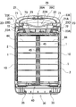
- FIG. 5 is a cross-sectional view taken along line VV of the power supply device of FIG. 1;
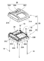
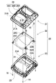
- FIG. 6 is a partially enlarged cross-sectional view of the power supply apparatus of FIG. 1 along the line VI-VI. It is an expanded sectional view of the canopy part shown in FIG. It is a disassembled perspective view of a canopy part.
- each element constituting the present invention may be configured such that a plurality of elements are constituted by the same member and one member is used in common as a plurality of elements, or conversely the function of one member is realized by a plurality of members It can be shared and realized.
- the contents described in some examples and embodiments may be applicable to other examples and embodiments.
- the power supply device shown below mainly demonstrates the example applied to the drive power supply of electric vehicles, such as an electric vehicle and an electric cart which drive
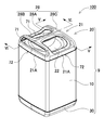
- FIG. 1 is a perspective view showing a power supply apparatus 100 according to an embodiment of the present invention
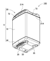
- FIG. 2 is a perspective view of the power supply apparatus 100 of FIG. 4 is an exploded perspective view of the power supply apparatus 100 of FIG. 3 as viewed obliquely from below
- FIG. 5 is a cross-sectional view of the power supply apparatus 100 of FIG. 1 taken along line VV
- FIG. Partially enlarged cross-sectional views of the device 100 taken along line VI-VI are shown. (Exterior case 9)
- the power supply device 100 shown in FIGS. 1 to 6 incorporates a battery assembly 40 inside the exterior case 9.
- the outer case 9 includes a cylindrical storage case 10 and a canopy 20, and the upper opening 11 of the storage case 10 is closed by the canopy 20.
- the storage case 10 incorporates the battery assembly 40, and a metal such as aluminum is cylindrical.
- the cylindrical storage case 10 closes the lower opening 12 with a bottom cover 30. In the illustrated storage case 10, the lower opening 12 is closed by the bottom cover 30, but the storage case can also be formed into an integral structure. (Inflow opening 71, discharge opening 72)
- the exterior case 9 does not have a watertight sealed structure.
- the exterior case 9 is provided with an inflow opening 71 of water at the boundary of the parts constituting the exterior case 9 without making the boundary part of the parts constituting the case a watertight structure by packing etc. Drain from the discharge opening 72 to the outside.
- the structure is such that the infiltrating water is discharged from the discharge opening 72 to the outside without adversely affecting the internal components such as the battery cell 1 and the like.
- a guide groove 73 for guiding the intruding water from the inflow opening 71 to the discharge opening 72 is provided in the inside of the outer case 9.
- both the inflow opening 71 and the discharge opening 72 are formed by the canopy 20 to prevent the intrusion of water into the storage case 10.
- the power supply device 100 shown in the figure is provided with an inflow opening 71 in the canopy 20, a discharge opening 72 in the boundary between the canopy 20 and the accommodation case 10, and a storage case incorporating the battery assembly 40. It prevents water from entering 10 (Canopy part 20)
- the canopy 20 does not consist of one part formed by integrally molding the whole. Although the whole can be integrally formed of plastic or the like and can be configured as one part, the degree of freedom of the design and shape of this canopy part is limited, and a high-quality and beautiful design can not be realized. In addition, if the canopy provided with the handle is integrally formed, the mold structure becomes difficult, and the shape can not be formed into an ideal shape due to restrictions.
- the canopy 20 shown in FIGS. 5 and 6 is composed of a plurality of parts.
- a gap formed between the components is used as the inflow opening 71 without sealing the connecting portion of each component to be sealed with a packing in a watertight manner.
- the gap formed at the connecting portion between the canopy 20 and the storage case 10 is used as the discharge opening 72, and the infiltrating water from the inflow opening 71 is drained to the outside without entering the inside of the storage case 10.
- the canopy 20 in the figure is composed of a plurality of parts consisting of the first case 21, the second case 22 and the third case 23 and has a beautiful appearance and is convenient to carry as a high-class design with the handle 28. Shape.
- each case can be efficiently formed with a mold having a simple structure.
- the canopy 20 realizes a structure that can be mass-produced easily and efficiently without forming a watertight structure by packing.
- the exterior case 9 in which the canopy 20 is composed of a plurality of parts forms the inflow opening 71 and the discharge opening 72 with the canopy 20, and the entry water from the inflow opening 71 of the canopy 20 is smoothly discharged from the discharge opening 72. Drain. Precisely, the canopy 20 forms an inflow opening 71 with a gap between parts constituting this, forms a discharge opening 72 with a gap between the lower end edge of the canopy 20 and the storage case 10, and It does not flow into the storage case 10. Furthermore, the channel resistance of the inflow opening 71 is larger than the channel resistance of the discharge opening 72 so that the infiltrating water is not accumulated in the outer case 9, in other words, the channel resistance of the discharge opening 72 is greater than the channel resistance of the inflow opening 71 It's smaller.
- the external case 9 has a larger amount of water which can be drained through the discharge opening 72 than the amount of water flowing into the external case 9 through the inflow opening 71 per unit time, and the infiltrating water flowing in through the inflow opening 71 can be rapidly Water is drained from the exterior case 9 and stagnant water does not stagnate in the exterior case 9. Furthermore, the inflow opening 71 and the discharge opening 72 are gaps extending along the upper opening 11 of the storage case 10. Since the power supply apparatus is provided with the inflow opening 71 and the discharge opening 72 along the upper opening 11 of the storage case 10, it is possible to rapidly drain the intruding water flowing in from the entire circumference.
- FIGS. 8 to 10 show an exploded perspective view of the canopy 20.
- FIG. The canopy 20 shown in the above figures has a three-layer structure of the first case 21, the second case 22 and the third case 23.
- the third case 23 is on the storage case 10, and the second case 22 is the third case.
- the first case 21 is disposed on the second case 22 above the second case 22.
- the third case 23 has a frame shape in which a handle frame 24 covering the lower surface of the handle portion 28 is integrally formed and provided, and is a frame portion serving as a base case disposed on the storage case 10.
- the second case 22 is a closed portion fixed on the third case 23 and closing the frame opening 25 of the third case 23.
- the first case 21 is a cover portion disposed on the second case 22 and providing the upper surface of the handle portion 28.
- the first case 21, the second case 22 and the third case 23 are manufactured by molding plastic.
- the canopy 20 has a handle 28 on the top surface.
- the handle portion 28 includes a grip portion 28A extending in the horizontal direction, an arch-like connecting portion 28B connected to one end of the grip portion 28A, and a rising connecting portion 28C connected to the other end.
- the handle portion 28 is configured by the first case 21 at the outer side and the third case 23 at the inner side. (First case 21)
- the first case 21 integrally molds the outer peripheral wall 21A placed on the opening edge of the upper opening 11 of the storage case 10 and the outside of the handle 28 connected to the outer peripheral wall 21A. doing.
- a clearance is provided between the first case 21 and the outer peripheral edge of the second case 22 to flow
- the opening 71 is used. Since the canopy 20 has a quadrangular outer shape, the overall shape of the second case 22 is also quadrilateral, and outer peripheral edges of four sides can be formed.
- the canopy 20 in the figure has the inflow openings 71 on the outer peripheral edges of the three sides without providing the inflow openings 71 on the outer peripheral edges of all the four sides of the second case 22, and the inner surface of the rising connecting portion 28C of the handle portion 28.
- the inflow opening is not provided on the upward outer peripheral edge 22a of one side approaching the.
- the upward outer peripheral edge 22a has a shape inclined upward and downward, and the upper end face thereof is disposed at the approach position of the inner surface of the handle portion 28 of the third case 23 so that the gap with the third case 23 is the handle portion 28. It is because it covers from above with the inner surface of and prevents the inflow of water from this crevice. (2nd case 22)
- the second case 22 has a plate shape that closes the frame opening 25 of the third case 23, and as a curved portion 22A that causes the central portion to project downward, the distance between the second case 22 and the central portion of the handle 28 is wide.
- This shape is characterized in that the gap under the handle portion 28 is widened without the handle portion 28 projecting high, and the user can smoothly put his finger under the handle portion 28 and carry it.
- the second case 22 is sandwiched between the first case 21 and the third case 23 and fixed to the third case 23.
- the second case 22 is provided with a connection piece 22B screwed to the third case 23 and an insertion piece 22C inserted into the third case 23 from the top to the bottom and connected.
- the connection piece 22B protrudes in the horizontal direction and is fixed by a set screw 15 screwed into the connection boss 23B of the third case 23.
- the insertion piece 22C protrudes downward and is inserted into and connected to a fitting hole 23C provided in the third case 23.
- the third case 23 includes an insertion peripheral wall 23A which is closely inserted to the inside of the entire circumference of the storage case 10.
- the insertion peripheral wall 23A rises to the inside of the outer peripheral wall 21A of the first case 21, and a discharge opening 72 is provided between the insertion peripheral wall 23A and the outer peripheral wall 21A.
- a gap is provided between the lower end edge of the outer peripheral wall 21A of the first case 21 and the upper end edge of the storage case 10, and further, the outer peripheral wall 21A and the third A gap is also provided between the upper portion of the insertion peripheral wall 23A of the case 23.
- the third case 23 is provided with a bottom plate 23D that curves and extends inward from the upper edge of the insertion peripheral wall 23A.
- the curved portion at the boundary between the upper portion of the insertion peripheral wall 23A and the bottom plate 23D has a gap with the outer peripheral wall 21A of the first case 21, and this gap is used as the discharge opening 72.
- the bottom plate 23D is provided with an inner peripheral wall 23E along the inner edge.
- the inner peripheral wall 23E is disposed on the inner side than the inflow opening 71, and a space between the inner peripheral wall 23E and the outer peripheral wall 21A is a guide groove 73 whose bottom is a bottom plate 23D.
- the inner peripheral wall 23E is disposed on the inner side of the inflow opening 71 in order to allow the intruding water that flows in from the inflow opening 71 and flows down into the guide groove 73 without leaking to the outside.
- the third case 23 is provided with a guide groove 73 for guiding the intruding water flowing in from the inflow opening 71 on the outside of the inner peripheral wall 23E, and guides the infiltrating water flowing in from the inflow opening 71 to the discharge opening 72.
- the guide groove 73 is disposed entirely below the inflow opening 71, and drains the intruding water from the inflow opening 71 from the discharge opening 72 to the outside without leaking.
- the discharge opening 72 has a smaller gap than the inflow opening 71 so as to make the water passage resistance smaller than the inflow opening 71 so that the intruding water is not smoothly drained and accumulated in the inside.
- the above-described canopy unit 20 is assembled by fixing the second case 22 to the third case 23 and screwing the third case 23 to the first case 21.
- the set screw 16 for fixing the third case 23 to the first case 21 is, as shown in FIG. 10, a connection boss 21B provided on the first case 21 by penetrating the third case 23 from the lower surface side of the third case 23 Screwed on.
- the battery assembly 40 is inserted into the storage case 10 in a fixed position of the storage case 10 with the battery assembly 40 fixed to the lower surface, as shown in FIGS. Be placed. (Battery assembly 40)
- the battery assembly 40 includes a plurality of secondary battery cells 1 as shown in FIG.
- the plurality of secondary battery cells 1 are arranged at fixed positions by the battery holder 44, and the battery end faces are connected by the lead plate 45, and the outer shape is arranged in a square pillar shape.
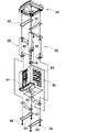
- the battery assembly 40 is fastened by a support frame 50 at its periphery, and is connected to the canopy 20 and the bottom cover 30 via a set screw 46 penetrating the support frame 50.
- the battery assembly 40 is fixed to the canopy 20 via a set screw 46 penetrating the support frame 50 upward.
- the battery assembly 40 fixed to the canopy 20 is housed in a state where the heat dissipation sheet 2 is in close contact with the side surface 43 and the aramid fiber sheet 3 is laminated on the surface of the heat dissipation sheet 2 It is inserted into the case 10.
- the bottom cover 30 is connected to the lower opening 12 to close the storage case 10 in which the battery assembly 40 is inserted.
- the set screw 46 penetrating the support frame 50 downward is inserted, and the nut 49 is screwed into the set screw 46 penetrating the bottom cover 30.
- the battery assembly 4 is fixed to the lower surface.
- the canopy 20 is fixed to the upper opening 11 of the storage case 10 and the bottom cover 30 is fixed to the lower opening 12 of the storage case 10.
- the power supply device 100 shown in FIG. 2 is provided with an output terminal 33 exposed on the bottom surface of the exterior case 9.
- the exterior case 9 in which the output terminal 33 is provided here is characterized in that water can be prevented from flowing from the output terminal 33.
- the output terminal 33 is provided to penetrate the metal rod from the inside of the case to the outside, the space between the output terminal 33 and the case is waterproofed by packing or the like.
- the waterproof structure by the packing can not prevent the entry of water due to the deterioration of the packing.
- the deterioration of the packing can not be completely eliminated, and it is extremely difficult to realize a reliable waterproof structure over a long period of time.
- the power supply device 100 of FIG. 2 exposes the output terminal 33 on the bottom surface, it is characterized in that the entry of water from the output terminal 33 can be reliably prevented in the used state.
- the exterior case 9 shown in the bottom view of FIG. 2 and the cross-sectional view of FIG. 5 is provided with a bottom outlet 35 at the bottom. Even if the intruding water can not be drained from the discharge opening 72, the power supply device 100 can prevent draining from the bottom drainage port 35 and accumulating in the inside. Further, since the bottom outlet 35 on the bottom opens downward, water does not infiltrate from here.
- the power supply device of the present invention can be conveniently used for applications used outdoors.
Landscapes
- Chemical & Material Sciences (AREA)
- Chemical Kinetics & Catalysis (AREA)
- Electrochemistry (AREA)
- General Chemical & Material Sciences (AREA)
- Battery Mounting, Suspending (AREA)
Abstract
簡単に組み立てできる構造としながら、長期間にわたって浸入水による弊害を確実に阻止する。 電池を内蔵する収納ケース(10)の上方開口部(11)を天蓋部(20)で閉塞して、天蓋部(20)でもって外装ケース(9)に流入開口(71)と排出開口(72)とを構成し、さらに天蓋部(20)には、流入開口(71)からの浸入水を排出開口(72)に案内するガイド溝(73)を設け、さらにまた、排出開口(72)の水路抵抗を流入開口(71)の水路抵抗の小さくして、浸入水を速やかに外部に排水する構造としている。
Description
本発明は、二次電池セルを内蔵する電源装置に関し、とくに屋外用に最適な防水構造の電源装置に関する。
電源装置は用途によって防水構造が要求される。たとえば、自転車や電動バイクのように屋外で使用される電源装置においては、全ての使用環境において水の弊害を皆無にはできず、外装ケースに防水構造が要求される。ケース内に浸入する水が、腐蝕、漏電、ショート、電子回路の誤動作など種々の弊害となるからである。
浸入水による弊害を防止するために、外装ケースを密閉された防水構造とする電源装置は開発されている。(特許文献1及び2参照)
これ等の電源装置は、外装ケースをパッキンで水密構造に密閉し、またはコネクタをパッキンで水密構造に外装ケースに固定する。外装ケースやコネクタを完全な密閉構造とする電源装置は、経年変化でパッキンが劣化して水が浸入する欠点がある。また、メンテナンス時において外装ケースの開閉に手間がかかる。とくに、開いた外装ケースを密閉するときに、完全に密閉できないと水が浸入する欠点もある。
これ等の電源装置は、外装ケースをパッキンで水密構造に密閉し、またはコネクタをパッキンで水密構造に外装ケースに固定する。外装ケースやコネクタを完全な密閉構造とする電源装置は、経年変化でパッキンが劣化して水が浸入する欠点がある。また、メンテナンス時において外装ケースの開閉に手間がかかる。とくに、開いた外装ケースを密閉するときに、完全に密閉できないと水が浸入する欠点もある。
外装ケースを水密構造に密閉する電源装置は、組み立てやメンテナンスに手間がかかる欠点がある。また、パッキンが劣化すると水が浸入するので、長期間にわたって浸入水による弊害を阻止するのが難しい欠点がある。
本発明は、従来の防水構造の電源装置の欠点を解消することを目的として開発されたもので、本発明の目的の一は、外装ケースの組み立てが簡単で、しかも長期間にわたって浸入水による弊害を防止できる防水構造の電源装置を提供することにある。
本発明の第1の側面に係る電源装置は、外装ケースに電池セルを内蔵してなる電源装置であって、前記外装ケースが、上方を開口して内部に前記電池セルを内蔵してなる収納ケースと、前記収納ケースの上方開口部を閉塞してなる天蓋部とを備えている。前記天蓋部は、外部の水を外装ケース内に流入させる流入開口と、前記流入開口から流入される浸入水を外部に排出する前記流入開口よりも水路抵抗の小さい排出開口とを形成している。さらに、前記天蓋部は、前記流入開口から流入される浸入水を前記排出開口に案内するガイド溝を備えてなることを特徴とする電源装置。
以上の電源装置は、外装ケースの組み立てが簡単で、しかも長期間に渡って浸入水による弊害を防止できる特徴がある。それは以上の電源装置が、外装ケースを収納ケースと天蓋部とで構成して、天蓋部に流入開口と排出開口とを設けて、外装ケースの天蓋部に設けた流入開口から内部に浸入する水を、天蓋部に設けられて流入開口よりも水路抵抗の小さい排出開口から外部に排出するからである。とくに以上の電源装置は、電池を内蔵する収納ケースの上に配置している天蓋部に流入開口と排出開口を設けて、浸入水を天蓋部から外部に排出するので、浸入水が電池内蔵の収納ケース内には流入することがなく、浸入水による電池の弊害を有効に防止できる特徴がある。また、流入開口と排出開口を設けた天蓋部を収納ケースに連結して組み立てできるので、外装ケースに流入開口と排出開口の両方を設けながら、組み立てを簡単にできる特徴を実現する。とくに、以上の電源装置は、従来のように、外装ケースをパッキン等で密閉構造としないので、パッキンが劣化して防水性能が低下することがなく、長期間にわたって優れた防水構造を保持し、しかも温度などの外的環境の厳しい使用環境においても、安定して防水構造を実現する。さらにまた、以上の電源装置は、天蓋部に排出開口を設けているので、電池の排出弁が開いて電池から排出される高温・高圧のガスを外装ケースからスムーズに外部に排出してより高い安全性を実現できる特徴も実現する。
また、第2の側面に係る電源装置によれば、上記構成に加えて、前記外装ケースの底部に出力端子を設けることができる。
さらに、第3の側面に係る電源装置によれば、上記何れかの構成に加えて、前記天蓋部を複数部品で構成し、前記流入開口を前記天蓋部を構成する部品の境界に設けて、前記排出開口を、前記天蓋部と前記収納ケースの境界部分に設けることができる。
さらにまた、第4の側面に係る電源装置によれば、上記構成に加えて、前記天蓋部が、前記収納ケースの上に配置してなる第3ケースと、前記第3ケースの上に配置してなる第2ケースと、前記第2ケースの上に配置してなる第1ケースとを備え、前記流入開口を前記第1ケースと前記第2ケースとの間に設けることができる。
さらにまた、第5の側面に係る電源装置によれば、上記構成に加えて、前記排出開口を前記第1ケースと前記収納ケースとの間に設けることができる。
さらにまた、第6の側面に係る電源装置によれば、上記構成に加えて、前記第1ケースが、前記収納ケースの上方開口縁の上に配置される外周壁を備え、前記外周壁と前記収納ケースとの間に排出開口を設けることができる。
さらにまた、第7の側面に係る電源装置によれば、上記何れかの構成に加えて、前記流入開口と前記排出開口を、前記収納ケースの上方開口部に沿って伸びる隙間とすることができる。
さらにまた、第8の側面に係る電源装置によれば、上記構成に加えて、前記第3ケースが、前記収納ケースの上方開口部から内側に密接して挿入される挿入周壁と、前記挿入周壁の上縁に連結してなる底プレートと、前記底プレートの内側に沿って設けてなる内部周壁とを備えて、前記挿入周壁は、前記第1ケースの前記外周壁の内側まで伸びて、前記外周壁との間に隙間を設けて排出開口とし、前記第3ケースが前記内部周壁の外側に前記底プレート部を溝底とする前記ガイド溝を設けることができる。
さらにまた、第9の側面に係る電源装置によれば、上記何れかの構成に加えて、前記外装ケースの底部に底部排水口を設けることができる。
以下、本発明の実施の形態を図面に基づいて説明する。ただし、以下に示す実施の形態は、本発明の技術思想を具体化するための構成を例示するものであって、本発明は以下のものに特定されない。また、特許請求の範囲に示される部材を、実施の形態の部材に特定するものでは決してない。特に実施の形態に記載されている構成部材の寸法、材質、形状、その相対的配置等は、特に特定的な記載がない限りは、本発明の範囲をそれのみに限定する趣旨ではなく、単なる説明例にすぎない。なお、各図面が示す部材の大きさや位置関係等は、説明を明確にするため誇張していることがある。さらに以下の説明において、同一の名称、符号については同一もしくは同質の部材を示しており、詳細説明を適宜省略する。さらに、本発明を構成する各要素は、複数の要素を同一の部材で構成して一の部材で複数の要素を兼用する態様としてもよいし、逆に一の部材の機能を複数の部材で分担して実現することもできる。また、一部の実施例、実施形態において説明された内容は、他の実施例、実施形態等に利用可能なものもある。
以下に示す電源装置は、主として、モータのみで走行する電気自動車や電動カートなどの電動車両の駆動用電源に適用する例を説明する。なお本発明の電源装置を、エンジンとモータの両方で走行するハイブリッド車に使用したり、電動車両以外の大出力が要求される用途、例えば家庭用、工場用の蓄電装置等に使用してもよい。
(実施形態1)
(実施形態1)
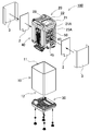
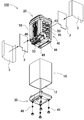
実施形態1に係る電源装置100を、図1~図6に示す。これらの図において、図1は本発明の一実施形態に係る電源装置100を示す斜視図、図2は図1の電源装置100を斜め下方から見た斜視図、図3は図1の電源装置100の分解斜視図、図4は図3の電源装置100を斜め下方から見た分解斜視図、図5は図1の電源装置100のV-V線における断面図、図6は図1の電源装置100のVI-VI線における一部拡大断面図を、それぞれ示している。
(外装ケース9)
(外装ケース9)
図1~図6に示す電源装置100は、外装ケース9の内部に電池集合体40を内蔵している。外装ケース9は筒状の収納ケース10と天蓋部20を備え、収納ケース10の上方開口部11を天蓋部20で閉塞している。収納ケース10は電池集合体40を内蔵し、アルミニウム等の金属を筒状としている。筒状の収納ケース10は、下方開口部12を底蓋部30で閉塞している。図の収納ケース10は下方開口部12を底蓋部30で閉塞するが、収納ケースは底蓋部を一体構造に成形することもできる。
(流入開口71、排出開口72)
(流入開口71、排出開口72)
外装ケース9は、水密に密閉された構造ではない。外装ケース9は、ケースを構成する部品の境界部分をパッキン等で水密構造とすることなく、外装ケース9を構成する部品の境界に水の流入開口71を設けて、流入開口71からの浸入水を排出開口72から外部に排水する。浸入水が電池セル1などの内部部品に悪影響を与えることなく排出開口72から外部に排出する構造としている。外装ケース9の内部には、流入開口71からの浸入水を排出開口72に案内するガイド溝73を設けている。さらに、電源装置100は、流入開口71と排出開口72の両方を天蓋部20で形成して、収納ケース10に浸入水が流入するのを阻止している。正確には、図の電源装置100は、流入開口71を天蓋部20に設けて、排出開口72を天蓋部20と収納ケース10との境界部分に設けて、電池集合体40を内蔵する収納ケース10への水の浸入を阻止している。
(天蓋部20)
(天蓋部20)
天蓋部20は、全体を一体的に成形してなる1部品では構成しない。全体をプラスチック等で一体的に成形して1部品で構成できるが、この天蓋部は、デザインや形状の自由度が制限され、高級で美しいデザインを実現できない。また、取っ手を設けた天蓋部を一体的に成形すると、金型構造が難しくなり、形状にも制約を受けて理想的な形状に成形できない。
図5と図6に示す天蓋部20は、複数の部品で構成する。この天蓋部20は、構成する各部品の連結部をパッキンで水密に密閉することなく、部品の間にできる隙間を流入開口71としている。また、天蓋部20と収納ケース10との連結部にできる隙間を排出開口72として、流入開口71からの浸入水を収納ケース10の内部に浸入させることなく外部に排水する。図の天蓋部20は、第1ケース21と、第2ケース22と、第3ケース23とからなる複数の部品で構成して、取っ手部28のある高級なデザインとして、美しい外観で持ち運びに便利な形状としている。また、各々のケースを簡単な構造の金型で能率よく成形できる構造としている。さらに、天蓋部20は、パッキンで水密構造とすることなく、簡単に能率よく多量生産できる構造を実現している。
天蓋部20を複数の部品で構成する外装ケース9は、天蓋部20でもって流入開口71と排出開口72を形成して、天蓋部20の流入開口71からの浸入水を排出開口72からスムーズに排水する。正確には、天蓋部20は、これを構成する部品の隙間で流入開口71を形成して、天蓋部20の下端縁と収納ケース10との隙間で排出開口72を形成して、浸入水を収納ケース10には流入しない構造としている。さらに、浸入水が外装ケース9内に溜まらないように、流入開口71の水路抵抗は排出開口72の水路抵抗よりも大きく、いいかえると、排出開口72の水路抵抗を流入開口71の水路抵抗よりも小さくしている。この外装ケース9は、単位時間に流入開口71を通過して外装ケース9に流入する水量よりも、排出開口72を通過して排水できる水量が多く、流入開口71から流入する浸入水を速やかに外装ケース9から排水して、外装ケース9に浸入水が停滞することがない。さらに、流入開口71と排出開口72は、収納ケース10の上方開口部11に沿って伸びる隙間としている。この電源装置は、収納ケース10の上方開口部11に沿って流入開口71と排出開口72を設けているので、全周から流入する浸入水を速やかに排水できる。
図5及び図6は、図1に示す電源装置100を互いに直交する方向に切断した断面図であって、図6は上部の一部拡大断面図を示している。また、図7は図5の要部拡大断面図を示している。さらに、図8~図10は、天蓋部20の分解斜視図を示している。以上の図に示す天蓋部20は、第1ケース21と第2ケース22と第3ケース23の3層構造で、第3ケース23を収納ケース10の上に、第2ケース22を第3ケース23の上に、第1ケース21を第2ケース22の上に配置している。第3ケース23は、取っ手部28の下面をカバーする取っ手枠24を一体的に成形して設けた枠形状で、収納ケース10の上に配置されるベースケースとなる枠部である。第2ケース22は第3ケース23の上に固定されて第3ケース23の枠開口部25を閉塞する閉塞部である。第1ケース21は第2ケース22の上に配置されて取っ手部28の上面を設けているカバー部である。
第1ケース21と第2ケース22と第3ケース23はプラスチックを成形して製作される。天蓋部20は上面に取っ手部28を設けている。取っ手部28は、水平方向に伸びるグリップ部28Aと、グリップ部28Aの一端に連結しているアーチ状連結部28Bと他端に連結している立ち上がり連結部28Cとからなる。取っ手部28は、外側を第1ケース21で、内側を第3ケース23で構成している。
(第1ケース21)
(第1ケース21)
第1ケース21は、収納ケース10の上方開口部11の開口縁の上に載せて配置される外周壁21Aと、この外周壁21Aに連結している取っ手部28の外側とを一体的に成形している。第1ケース21は、第2ケース22を挟んで第3ケース23に固定される状態で、図5~図7に示すように、第2ケース22の外周縁との間に隙間を設けて流入開口71としている。天蓋部20は、外形を四角形とするので、第2ケース22の全体形状も四角形となって、4辺の外周縁ができる。図の天蓋部20は、第2ケース22の4辺全ての外周縁に流入開口71を設けることなく、3辺の外周縁に流入開口71を設けて、取っ手部28の立ち上がり連結部28Cの内面に接近する1辺の上向き外周縁22aには流入開口を設けていない。上向き外周縁22aは、ここに向かって上り勾配に傾斜する形状として、その上端面を第3ケース23の取っ手部28内面の接近位置に配置して、第3ケース23との隙間を取っ手部28の内面で上からカバーして、この隙間からの水の流入を阻止しているからである。
(第2ケース22)
(第2ケース22)
第2ケース22は、第3ケース23の枠開口部25を閉塞する板状で、中央部を下方に突出させる湾曲部22Aとして、取っ手部28の中央部との間隔を広くしている。この形状は、取っ手部28を高く突出させることなく、取っ手部28の下の隙間を広くして、ユーザーが取っ手部28の下にスムーズに指を入れて持ち運びできる特徴がある。
第2ケース22は、第1ケース21と第3ケース23に挟まれて第3ケース23に固定される。第2ケース22は、第3ケース23にネジ止めされる連結片22Bと、第3ケース23に上から下に挿入して連結される挿入片22Cとを設けている。連結片22Bは水平方向に突出し、第3ケース23の連結ボス23Bにねじ込まれる止ネジ15で固定される。挿入片22Cは下方に突出して、第3ケース23に設けられた嵌合穴23Cに挿入して連結される。
(第3ケース23)
(第3ケース23)
第3ケース23は、収納ケース10全周の内側に密接して挿入される挿入周壁23Aを備える。挿入周壁23Aは、第1ケース21の外周壁21Aの内側まで立ち上がって、外周壁21Aとの間に排出開口72を設けている。収納ケース10の上端縁に沿って排出開口72を設けるために、第1ケース21の外周壁21Aの下端縁と収納ケース10上端縁との間に隙間を設け、さらに、外周壁21Aと第3ケース23の挿入周壁23Aの上部との間にも隙間を設けている。第3ケース23は、挿入周壁23Aの上縁から湾曲して内側に伸びる底プレート23Dを設けている。挿入周壁23Aの上部と底プレート23Dとの境界部分の湾曲部は、第1ケース21の外周壁21Aとの間に隙間があって、この隙間を排出開口72としている。底プレート23Dは、内側縁に沿って内部周壁23Eを設けている。内部周壁23Eは、流入開口71よりも内側に配置されて、外周壁21Aとの間を、底プレート23Dを溝底とするガイド溝73としている。内部周壁23Eは、流入開口71から浸入して流れ落ちる浸入水を外部に漏らさずガイド溝73に流入させるために、流入開口71よりも内側に配置される。第3ケース23は、流入開口71から流入される浸入水を案内するガイド溝73を内部周壁23Eの外側に設けて、流入開口71から流入する浸入水を排出開口72に案内する。ガイド溝73は、流入開口71の下方の全体に配置されて、流入開口71からの浸入水を漏らさず排出開口72から外部に排水する。排出開口72は、浸入水をスムーズに排水して内部に溜まらないように、流入開口71よりも隙間を広くして、流入開口71よりも水路抵抗を小さくしている。
以上の天蓋部20は、第2ケース22を第3ケース23に固定し、第3ケース23を第1ケース21にネジ止めして組み立てられる。第3ケース23を第1ケース21に固定する止ネジ16は、図10に示すように、第3ケース23の下面側から第3ケース23を貫通して第1ケース21に設けた連結ボス21Bにねじ込まれる。さらに、天蓋部20は、図3と図4に示すように、下面に電池集合体40が固定された状態で、電池集合体40が収納ケース10に挿入されて、収納ケース10の定位置に配置される。
(電池集合体40)
(電池集合体40)
電池集合体40は、図5に示すように複数の二次電池セル1を備えている。電池集合体40は、複数の二次電池セル1を電池ホルダ44で定位置に配置すると共に、電池端面をリード板45で接続して、外形を四角柱状とする形状に配置している。電池集合体40は、図11に示すように、周囲が支持フレーム50で締結されると共に、この支持フレーム50を貫通する止ネジ46を介して天蓋部20及び底蓋部30に連結される。
電池集合体40は、図11に示すように、支持フレーム50を上方に向かって貫通する止ネジ46を介して天蓋部20に固定される。天蓋部20に固定された電池集合体40は、図3と図4に示すように、側面43に放熱シート2を密着させて、放熱シート2の表面にアラミド繊維シート3を積層した状態で収納ケース10に挿入される。電池集合体40が挿入された収納ケース10は下方開口部12に底蓋部30が連結されて閉塞される。底蓋部30は、図4と図11に示すように、支持フレーム50を下方に向かって貫通する止ネジ46が挿通されると共に、底蓋部30を貫通する止ネジ46にナット49がねじ込まれて電池集合体4の下面に固定される。以上のようにして、天蓋部20を収納ケース10の上方開口部11に、底蓋部30を収納ケース10の下方開口部12に固定する。
さらに、図2に示す電源装置100は、外装ケース9の底面に露出する出力端子33を設けている。ここに出力端子33を設ける外装ケース9は、出力端子33から水が流入するのを阻止できる特徴がある。出力端子33は、ケース内から外部に金属ロッドを貫通して設けられるので、ケースとの間をパッキン等で防水構造としている。パッキンによる防水構造は、パッキンの劣化が原因で水が浸入するのを阻止できない。とくにパッキンの劣化を皆無にはできず、長期間にわたる確実な防水構造の実現は極めて難しい。図2の電源装置100は、底面に出力端子33を露出させるので、使用状態で出力端子33からの水の浸入を確実に防止できる特徴がある。
さらに、図2の底面図と図5の断面図に示す外装ケース9は、底部に底部排水口35を設けている。この電源装置100は、仮に浸入水が排出開口72から排水できないとしても、底部排水口35から排水して内部に溜まるのを防止できる。また、底面の底部排水口35は下向きに開口するので、ここから水が浸入することがない。
本発明の電源装置は、屋外で使用される用途に便利に使用できる。
100…電源装置
1…二次電池セル
2…放熱シート
3…アラミド繊維シート
9…外装ケース
10…収納ケース
11…上方開口部
12…下方開口部
15…止ネジ
16…止ネジ
20…天蓋部
21…第1ケース
21A…外周壁
21B…連結ボス
22…第2ケース
22A…湾曲部
22B…連結片
22C…挿入片
22a…上向き外周縁
23…第3ケース
23A…挿入周壁
23B…連結ボス
23C…嵌合穴
23D…底プレート
23E…内部周壁
24…取っ手枠
25…枠開口部
28…取っ手部
28A…グリップ部
28B…アーチ状連結部
28C…立ち上がり連結部
30…底蓋部
33…出力端子
35…底部排水口
40…電池集合体
43…側面
44…電池ホルダ
45…リード板
46…止ネジ
49…ナット
50…支持フレーム
71…流入開口
72…排出開口
73…ガイド溝
Claims (9)
- 外装ケースに電池セルを内蔵してなる電源装置であって、
前記外装ケースが、
上方を開口して内部に前記電池セルを内蔵してなる収納ケースと、
前記収納ケースの上方開口部を閉塞してなる天蓋部とを備え、
前記天蓋部が、
外部の水を外装ケース内に流入させる流入開口と、
前記流入開口から流入される浸入水を外部に排出する前記流入開口よりも水路抵抗の小さい排出開口とを形成し、
さらに、前記天蓋部が、
前記流入開口から流入される浸入水を前記排出開口に案内するガイド溝を備えてなることを特徴とする電源装置。 - 請求項1に記載される電源装置であって、
前記外装ケースの底部に出力端子を設けてなることを特徴とする電源装置。 - 請求項1または2に記載される電源装置であって、
前記天蓋部が複数部品からなり、
前記流入開口が前記天蓋部を構成する部品の境界に設けられ、
前記排出開口が、前記天蓋部と前記収納ケースの境界部分に設けられてなることを特徴とする電源装置。 - 請求項3に記載される電源装置であって、
前記天蓋部が、
前記収納ケースの上に配置してなる第3ケースと、
前記第3ケースの上に配置してなる第2ケースと、
前記第2ケースの上に配置してなる第1ケースとを備え、
前記流入開口が前記第1ケースと前記第2ケースとの間に設けられてなることを特徴とする電源装置。 - 請求項4に記載される電源装置であって、
前記排出開口が前記第1ケースと前記収納ケースとの間に設けてなることを特徴とする電源装置。 - 請求項5に記載される電源装置であって、
前記第1ケースが、前記収納ケースの上方開口縁の上に配置される外周壁を備え、
前記外周壁と前記収納ケースとの間に排出開口が設けられてなることを特徴とする電源装置。 - 請求項1ないし6のいずれかに記載される電源装置であって、
前記流入開口と前記排出開口が、前記収納ケースの上方開口部に沿って伸びる隙間であることを特徴とする電源装置。 - 請求項4ないし6のいずれかに記載される電源装置であって、
前記第3ケースが、前記収納ケースの上方開口部から内側に密接して挿入される挿入周壁と、
前記挿入周壁の上縁に連結してなる底プレートと、前記底プレートの内側に沿って設けてなる内部周壁とを備え、
前記挿入周壁は、前記第1ケースの前記外周壁の内側まで伸びて、前記外周壁との間に隙間を設けて排出開口としており、
前記第3ケースが前記内部周壁の外側に前記底プレート部を溝底とする前記ガイド溝を設けてなることを特徴とする電源装置。 - 請求項1ないし8のいずれかに記載される電源装置であって、
前記外装ケースの底部に底部排水口を設けてなることを特徴とする電源装置。
Priority Applications (3)
| Application Number | Priority Date | Filing Date | Title |
|---|---|---|---|
| CN201880062896.2A CN111164785B (zh) | 2017-09-29 | 2018-09-03 | 电源装置 |
| JP2019544480A JP7233371B2 (ja) | 2017-09-29 | 2018-09-03 | 電源装置 |
| PH12020550138A PH12020550138A1 (en) | 2017-09-29 | 2020-03-25 | Power source apparatus |
Applications Claiming Priority (2)
| Application Number | Priority Date | Filing Date | Title |
|---|---|---|---|
| JP2017190041 | 2017-09-29 | ||
| JP2017-190041 | 2017-09-29 |
Publications (1)
| Publication Number | Publication Date |
|---|---|
| WO2019065109A1 true WO2019065109A1 (ja) | 2019-04-04 |
Family
ID=65900963
Family Applications (1)
| Application Number | Title | Priority Date | Filing Date |
|---|---|---|---|
| PCT/JP2018/032647 Ceased WO2019065109A1 (ja) | 2017-09-29 | 2018-09-03 | 電源装置 |
Country Status (4)
| Country | Link |
|---|---|
| JP (1) | JP7233371B2 (ja) |
| CN (1) | CN111164785B (ja) |
| PH (1) | PH12020550138A1 (ja) |
| WO (1) | WO2019065109A1 (ja) |
Cited By (2)
| Publication number | Priority date | Publication date | Assignee | Title |
|---|---|---|---|---|
| JP2022016096A (ja) * | 2020-07-10 | 2022-01-21 | 本田技研工業株式会社 | 蓄電装置 |
| JP7056795B1 (ja) | 2021-12-03 | 2022-04-19 | Tdk株式会社 | バッテリーケースおよび蓄電池システム |
Families Citing this family (1)
| Publication number | Priority date | Publication date | Assignee | Title |
|---|---|---|---|---|
| EP4212471B1 (en) * | 2021-10-22 | 2025-05-14 | Crown Equipment Corporation | Battery guide blocks for a battery receiving space of a materials handling vehicle, and materials handling vehicles incorporating the same |
Citations (3)
| Publication number | Priority date | Publication date | Assignee | Title |
|---|---|---|---|---|
| JP2003308134A (ja) * | 2002-04-18 | 2003-10-31 | Casio Comput Co Ltd | 携帯情報機器 |
| JP2014003019A (ja) * | 2012-06-20 | 2014-01-09 | Samsung Sdi Co Ltd | 二次電池およびそのモジュール |
| JP2015053164A (ja) * | 2013-09-06 | 2015-03-19 | セイコーエプソン株式会社 | 携帯型電子機器 |
Family Cites Families (12)
| Publication number | Priority date | Publication date | Assignee | Title |
|---|---|---|---|---|
| JPH0680236U (ja) * | 1993-04-22 | 1994-11-08 | 市光工業株式会社 | イルミネーション付きスイッチ装置 |
| JPH1040894A (ja) * | 1996-07-19 | 1998-02-13 | Daito Kasei Kk | 蓄電池 |
| JP2002127941A (ja) * | 2000-10-26 | 2002-05-09 | Asmo Co Ltd | エンジンルームの被水防止構造 |
| JP4768543B2 (ja) * | 2006-08-09 | 2011-09-07 | 株式会社東芝 | 電子機器 |
| CN201112211Y (zh) * | 2007-09-14 | 2008-09-10 | 李伟高 | 导流式防水键盘 |
| CN101630755A (zh) * | 2009-05-12 | 2010-01-20 | 深圳市山木电池科技有限公司 | 一种新型电动汽车电池 |
| CN201820569U (zh) * | 2010-09-15 | 2011-05-04 | 南通茂业电子科技有限公司 | 一种电永磁吸盘充退磁控制器 |
| JP2014157695A (ja) * | 2013-02-15 | 2014-08-28 | Omron Automotive Electronics Co Ltd | スイッチ装置 |
| CN104218193B (zh) * | 2014-07-30 | 2017-10-31 | 浙江超威创元实业有限公司 | 一种具有防火防爆装置的锂电池及应用该电池的电动车 |
| CN204760785U (zh) * | 2015-06-30 | 2015-11-11 | 南京博路电气有限公司 | 一种户外环网柜 |
| CN205050896U (zh) * | 2015-09-28 | 2016-02-24 | 浙江天能能源科技有限公司 | 一种密封设计的电池箱体 |
| JP6367400B2 (ja) * | 2017-02-23 | 2018-08-01 | 株式会社マキタ | バッテリパック |
-
2018
- 2018-09-03 WO PCT/JP2018/032647 patent/WO2019065109A1/ja not_active Ceased
- 2018-09-03 CN CN201880062896.2A patent/CN111164785B/zh active Active
- 2018-09-03 JP JP2019544480A patent/JP7233371B2/ja active Active
-
2020
- 2020-03-25 PH PH12020550138A patent/PH12020550138A1/en unknown
Patent Citations (3)
| Publication number | Priority date | Publication date | Assignee | Title |
|---|---|---|---|---|
| JP2003308134A (ja) * | 2002-04-18 | 2003-10-31 | Casio Comput Co Ltd | 携帯情報機器 |
| JP2014003019A (ja) * | 2012-06-20 | 2014-01-09 | Samsung Sdi Co Ltd | 二次電池およびそのモジュール |
| JP2015053164A (ja) * | 2013-09-06 | 2015-03-19 | セイコーエプソン株式会社 | 携帯型電子機器 |
Cited By (4)
| Publication number | Priority date | Publication date | Assignee | Title |
|---|---|---|---|---|
| JP2022016096A (ja) * | 2020-07-10 | 2022-01-21 | 本田技研工業株式会社 | 蓄電装置 |
| JP7703302B2 (ja) | 2020-07-10 | 2025-07-07 | 本田技研工業株式会社 | 蓄電装置 |
| JP7056795B1 (ja) | 2021-12-03 | 2022-04-19 | Tdk株式会社 | バッテリーケースおよび蓄電池システム |
| JP2023082793A (ja) * | 2021-12-03 | 2023-06-15 | Tdk株式会社 | バッテリーケースおよび蓄電池システム |
Also Published As
| Publication number | Publication date |
|---|---|
| CN111164785B (zh) | 2022-12-06 |
| JP7233371B2 (ja) | 2023-03-06 |
| JPWO2019065109A1 (ja) | 2020-10-22 |
| PH12020550138A1 (en) | 2020-12-07 |
| CN111164785A (zh) | 2020-05-15 |
Similar Documents
| Publication | Publication Date | Title |
|---|---|---|
| CA2772276C (en) | Telecommunications enclosures | |
| JP3223625U (ja) | 電動二輪車のバッテリー構造 | |
| JP7233371B2 (ja) | 電源装置 | |
| CN102196702B (zh) | 防水型电子设备的箱体 | |
| WO2009156363A1 (fr) | Echangeur de chaleur comportant un faisceau d'echange de chaleur et un boitier | |
| JP6938541B2 (ja) | 防水構造のバッテリシステム | |
| JP2018067735A (ja) | 電子制御装置 | |
| JP7114918B2 (ja) | 電子制御装置 | |
| FR2984478A1 (fr) | Echangeur de chaleur, ensemble d'un tel echangeur et d'une ou de boites collectrices, module d'admission d'air comprenant un tel ensemble | |
| EP0289406A1 (fr) | Echangeur de chaleur à deux étages et son procédé de montage | |
| JP5168975B2 (ja) | 蓄電池 | |
| CN108807736A (zh) | 一种防水结构组件及水上动力装备 | |
| JP7302015B2 (ja) | 電気回路装置 | |
| JP2010215113A (ja) | 車両用フード | |
| JP5530420B2 (ja) | 合流ます | |
| FR3097955A1 (fr) | Dispositif refroidisseur d’un ou plusieurs modules de stockage d’energie electrique | |
| JP6675777B2 (ja) | 電気機器収納用箱 | |
| KR100894865B1 (ko) | 조립형 싱크 보울 | |
| JP5480603B2 (ja) | 配線引込口装置 | |
| CN205882257U (zh) | 一种防水电控盒 | |
| FR2954464B1 (fr) | Separateur de flux d'air bidirectionnel pour installation a double flux | |
| JP5158967B2 (ja) | バッテリ直上ヒューズボックス | |
| JP4257318B2 (ja) | 簡易防水型筐体 | |
| JP5619454B2 (ja) | 電気接続箱 | |
| CN223053071U (zh) | 防水安装组件及视频监控系统 |
Legal Events
| Date | Code | Title | Description |
|---|---|---|---|
| 121 | Ep: the epo has been informed by wipo that ep was designated in this application |
Ref document number: 18860712 Country of ref document: EP Kind code of ref document: A1 |
|
| ENP | Entry into the national phase |
Ref document number: 2019544480 Country of ref document: JP Kind code of ref document: A |
|
| NENP | Non-entry into the national phase |
Ref country code: DE |
|
| 122 | Ep: pct application non-entry in european phase |
Ref document number: 18860712 Country of ref document: EP Kind code of ref document: A1 |