WO2019064882A1 - 油分離器 - Google Patents
油分離器 Download PDFInfo
- Publication number
- WO2019064882A1 WO2019064882A1 PCT/JP2018/028363 JP2018028363W WO2019064882A1 WO 2019064882 A1 WO2019064882 A1 WO 2019064882A1 JP 2018028363 W JP2018028363 W JP 2018028363W WO 2019064882 A1 WO2019064882 A1 WO 2019064882A1
- Authority
- WO
- WIPO (PCT)
- Prior art keywords
- oil
- separator
- curved portion
- wall
- oil separator
- Prior art date
Links
Images


Classifications
-
- F—MECHANICAL ENGINEERING; LIGHTING; HEATING; WEAPONS; BLASTING
- F25—REFRIGERATION OR COOLING; COMBINED HEATING AND REFRIGERATION SYSTEMS; HEAT PUMP SYSTEMS; MANUFACTURE OR STORAGE OF ICE; LIQUEFACTION SOLIDIFICATION OF GASES
- F25B—REFRIGERATION MACHINES, PLANTS OR SYSTEMS; COMBINED HEATING AND REFRIGERATION SYSTEMS; HEAT PUMP SYSTEMS
- F25B31/00—Compressor arrangements
- F25B31/002—Lubrication
- F25B31/004—Lubrication oil recirculating arrangements
-
- B—PERFORMING OPERATIONS; TRANSPORTING
- B01—PHYSICAL OR CHEMICAL PROCESSES OR APPARATUS IN GENERAL
- B01D—SEPARATION
- B01D45/00—Separating dispersed particles from gases or vapours by gravity, inertia, or centrifugal forces
- B01D45/12—Separating dispersed particles from gases or vapours by gravity, inertia, or centrifugal forces by centrifugal forces
- B01D45/16—Separating dispersed particles from gases or vapours by gravity, inertia, or centrifugal forces by centrifugal forces generated by the winding course of the gas stream, the centrifugal forces being generated solely or partly by mechanical means, e.g. fixed swirl vanes
-
- B—PERFORMING OPERATIONS; TRANSPORTING
- B01—PHYSICAL OR CHEMICAL PROCESSES OR APPARATUS IN GENERAL
- B01D—SEPARATION
- B01D45/00—Separating dispersed particles from gases or vapours by gravity, inertia, or centrifugal forces
- B01D45/12—Separating dispersed particles from gases or vapours by gravity, inertia, or centrifugal forces by centrifugal forces
-
- B—PERFORMING OPERATIONS; TRANSPORTING
- B04—CENTRIFUGAL APPARATUS OR MACHINES FOR CARRYING-OUT PHYSICAL OR CHEMICAL PROCESSES
- B04C—APPARATUS USING FREE VORTEX FLOW, e.g. CYCLONES
- B04C5/00—Apparatus in which the axial direction of the vortex is reversed
- B04C5/02—Construction of inlets by which the vortex flow is generated, e.g. tangential admission, the fluid flow being forced to follow a downward path by spirally wound bulkheads, or with slightly downwardly-directed tangential admission
- B04C5/04—Tangential inlets
-
- B—PERFORMING OPERATIONS; TRANSPORTING
- B04—CENTRIFUGAL APPARATUS OR MACHINES FOR CARRYING-OUT PHYSICAL OR CHEMICAL PROCESSES
- B04C—APPARATUS USING FREE VORTEX FLOW, e.g. CYCLONES
- B04C5/00—Apparatus in which the axial direction of the vortex is reversed
- B04C5/08—Vortex chamber constructions
- B04C5/081—Shapes or dimensions
-
- B—PERFORMING OPERATIONS; TRANSPORTING
- B04—CENTRIFUGAL APPARATUS OR MACHINES FOR CARRYING-OUT PHYSICAL OR CHEMICAL PROCESSES
- B04C—APPARATUS USING FREE VORTEX FLOW, e.g. CYCLONES
- B04C5/00—Apparatus in which the axial direction of the vortex is reversed
- B04C5/08—Vortex chamber constructions
- B04C5/103—Bodies or members, e.g. bulkheads, guides, in the vortex chamber
-
- F—MECHANICAL ENGINEERING; LIGHTING; HEATING; WEAPONS; BLASTING
- F04—POSITIVE - DISPLACEMENT MACHINES FOR LIQUIDS; PUMPS FOR LIQUIDS OR ELASTIC FLUIDS
- F04B—POSITIVE-DISPLACEMENT MACHINES FOR LIQUIDS; PUMPS
- F04B39/00—Component parts, details, or accessories, of pumps or pumping systems specially adapted for elastic fluids, not otherwise provided for in, or of interest apart from, groups F04B25/00 - F04B37/00
- F04B39/04—Measures to avoid lubricant contaminating the pumped fluid
-
- F—MECHANICAL ENGINEERING; LIGHTING; HEATING; WEAPONS; BLASTING
- F04—POSITIVE - DISPLACEMENT MACHINES FOR LIQUIDS; PUMPS FOR LIQUIDS OR ELASTIC FLUIDS
- F04C—ROTARY-PISTON, OR OSCILLATING-PISTON, POSITIVE-DISPLACEMENT MACHINES FOR LIQUIDS; ROTARY-PISTON, OR OSCILLATING-PISTON, POSITIVE-DISPLACEMENT PUMPS
- F04C18/00—Rotary-piston pumps specially adapted for elastic fluids
- F04C18/08—Rotary-piston pumps specially adapted for elastic fluids of intermeshing-engagement type, i.e. with engagement of co-operating members similar to that of toothed gearing
- F04C18/12—Rotary-piston pumps specially adapted for elastic fluids of intermeshing-engagement type, i.e. with engagement of co-operating members similar to that of toothed gearing of other than internal-axis type
- F04C18/14—Rotary-piston pumps specially adapted for elastic fluids of intermeshing-engagement type, i.e. with engagement of co-operating members similar to that of toothed gearing of other than internal-axis type with toothed rotary pistons
- F04C18/16—Rotary-piston pumps specially adapted for elastic fluids of intermeshing-engagement type, i.e. with engagement of co-operating members similar to that of toothed gearing of other than internal-axis type with toothed rotary pistons with helical teeth, e.g. chevron-shaped, screw type
- F04C18/165—Rotary-piston pumps specially adapted for elastic fluids of intermeshing-engagement type, i.e. with engagement of co-operating members similar to that of toothed gearing of other than internal-axis type with toothed rotary pistons with helical teeth, e.g. chevron-shaped, screw type having more than two rotary pistons with parallel axes
-
- F—MECHANICAL ENGINEERING; LIGHTING; HEATING; WEAPONS; BLASTING
- F04—POSITIVE - DISPLACEMENT MACHINES FOR LIQUIDS; PUMPS FOR LIQUIDS OR ELASTIC FLUIDS
- F04C—ROTARY-PISTON, OR OSCILLATING-PISTON, POSITIVE-DISPLACEMENT MACHINES FOR LIQUIDS; ROTARY-PISTON, OR OSCILLATING-PISTON, POSITIVE-DISPLACEMENT PUMPS
- F04C29/00—Component parts, details or accessories of pumps or pumping installations, not provided for in groups F04C18/00 - F04C28/00
- F04C29/02—Lubrication; Lubricant separation
- F04C29/026—Lubricant separation
-
- F—MECHANICAL ENGINEERING; LIGHTING; HEATING; WEAPONS; BLASTING
- F25—REFRIGERATION OR COOLING; COMBINED HEATING AND REFRIGERATION SYSTEMS; HEAT PUMP SYSTEMS; MANUFACTURE OR STORAGE OF ICE; LIQUEFACTION SOLIDIFICATION OF GASES
- F25B—REFRIGERATION MACHINES, PLANTS OR SYSTEMS; COMBINED HEATING AND REFRIGERATION SYSTEMS; HEAT PUMP SYSTEMS
- F25B43/00—Arrangements for separating or purifying gases or liquids; Arrangements for vaporising the residuum of liquid refrigerant, e.g. by heat
- F25B43/02—Arrangements for separating or purifying gases or liquids; Arrangements for vaporising the residuum of liquid refrigerant, e.g. by heat for separating lubricants from the refrigerant
-
- B—PERFORMING OPERATIONS; TRANSPORTING
- B01—PHYSICAL OR CHEMICAL PROCESSES OR APPARATUS IN GENERAL
- B01J—CHEMICAL OR PHYSICAL PROCESSES, e.g. CATALYSIS OR COLLOID CHEMISTRY; THEIR RELEVANT APPARATUS
- B01J8/00—Chemical or physical processes in general, conducted in the presence of fluids and solid particles; Apparatus for such processes
- B01J8/005—Separating solid material from the gas/liquid stream
- B01J8/0055—Separating solid material from the gas/liquid stream using cyclones
-
- F—MECHANICAL ENGINEERING; LIGHTING; HEATING; WEAPONS; BLASTING
- F25—REFRIGERATION OR COOLING; COMBINED HEATING AND REFRIGERATION SYSTEMS; HEAT PUMP SYSTEMS; MANUFACTURE OR STORAGE OF ICE; LIQUEFACTION SOLIDIFICATION OF GASES
- F25B—REFRIGERATION MACHINES, PLANTS OR SYSTEMS; COMBINED HEATING AND REFRIGERATION SYSTEMS; HEAT PUMP SYSTEMS
- F25B2400/00—General features or devices for refrigeration machines, plants or systems, combined heating and refrigeration systems or heat-pump systems, i.e. not limited to a particular subgroup of F25B
- F25B2400/02—Centrifugal separation of gas, liquid or oil
-
- F—MECHANICAL ENGINEERING; LIGHTING; HEATING; WEAPONS; BLASTING
- F25—REFRIGERATION OR COOLING; COMBINED HEATING AND REFRIGERATION SYSTEMS; HEAT PUMP SYSTEMS; MANUFACTURE OR STORAGE OF ICE; LIQUEFACTION SOLIDIFICATION OF GASES
- F25B—REFRIGERATION MACHINES, PLANTS OR SYSTEMS; COMBINED HEATING AND REFRIGERATION SYSTEMS; HEAT PUMP SYSTEMS
- F25B2400/00—General features or devices for refrigeration machines, plants or systems, combined heating and refrigeration systems or heat-pump systems, i.e. not limited to a particular subgroup of F25B
- F25B2400/23—Separators
Definitions
- the present invention relates to a centrifugal oil separator.
- Forming a curved portion in the inflow pipe increases the space for installing the oil separator.
- An object of the present invention is to miniaturize an oil separator having a curved portion in an inflow pipe.
- the first aspect is a centrifugal type oil separator, which comprises a cylindrical separator body (70), a fluid containing oil, introduced into the separator body (70) and a curved portion (60). Oil having an inflow pipe (50) and the peripheral wall (71) of the separator body (70) and the inflow pipe (50) have a common part (C) shared with each other It is a separator.
- the oil separator (40) can be miniaturized.
- a second aspect is the oil separator according to the first aspect, wherein the sharing portion (C) is provided in the curved portion (60) of the inflow pipe (50).
- the oil separator (40) can be miniaturized by providing the sharing portion (C) in the curved portion (60) having a relatively large installation space.
- a third aspect is according to the second aspect, wherein the curved portion (60) is formed substantially flush with the peripheral wall (71) of the separator body (70) as the sharing portion (C) It is an oil separator characterized by including one wall (61).
- the shape of the peripheral wall (71) of the separator body (70) can be simplified.
- a fourth aspect is the oil separator according to the third aspect, wherein a shape of a cross section perpendicular to the axis of the inner surface (61a) of the first wall (61) is flat.
- the pipe diameter (diameter) of the curved portion (60) can be reduced.
- the curved portion (60) bulges radially outward from the peripheral wall (71) of the separator body (70).
- An oil separator characterized in that it comprises a wall (62).
- the surface area of the curved portion (60) exposed to the outside is increased.
- a sixth aspect is according to any one of the second to fifth aspects, wherein the curved portion (60) bulges radially inward from the peripheral wall (71) of the separator body (70).
- An oil separator characterized in that it comprises a wall (66).
- the overall radial size of the curved portion (60) can be reduced.
- the axis L1 of the inlet (51a) of the inflow pipe (50) is a tangent L2 of the outer peripheral surface of the separator body (70)
- An oil separator characterized in that it is also offset towards the center of the separator body (70).
- the overall size of the oil separator (40) can be reduced, and the overall length of the curved portion (60) can be increased.
- the eighth aspect is the oil separator according to any one of the first to seventh aspects, wherein the separator body (70) and the inflow pipe (50) have an integral structure made of castings. It is.
- the curved portion (60) has an inner surface (61a) having a tapered shape as it goes radially outward. It is an oil separator characterized by the above.
- oil separated using centrifugal force can be collected at the tapered inner surface (61a) of the bending portion (60).
- a tenth aspect is the oil separator according to any one of the first to ninth aspects, wherein an oil removing hole (90) is formed in the curved portion (60).
- the oil of the bending portion (60) can be discharged to the outside of the bending portion (60) through the oil removal hole (90).
- An eleventh aspect according to the tenth aspect includes the passage member (91) forming an oil passage (92) communicating with the oil removal hole (90), the passage member (91) being the curved portion 60) and an oil separator characterized in that it is an integral structure with at least one of the separator body (70).
- the oil separator having the passage member (91) can be miniaturized.
- the twelfth aspect relates to a compression mechanism (30) for compressing a fluid, and the oil separator according to any one of the first to eleventh aspects, which targets the fluid discharged from the compression mechanism (30). And (40).
- the compressor having the oil separator (40) can be miniaturized.
- a casing (11) accommodating the compression mechanism (30) is provided, and the oil separator (40) constitutes a part of the casing (11). It is a compressor characterized by the above.
- the compressor can be miniaturized.
- FIG. 1 is a longitudinal sectional view showing an entire configuration of a compressor according to the embodiment.
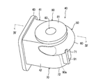
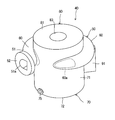
- FIG. 2 is a side perspective view of the oil separator.
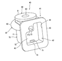
- FIG. 3 is a perspective view of the oil separator as viewed from the flange side.
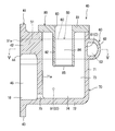
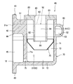
- FIG. 4 is an enlarged vertical sectional view of the oil separator in FIG.
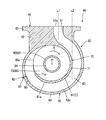
- FIG. 5 is a cross-sectional view taken along line VV of FIG.
- FIG. 6 is a cross-sectional view perpendicular to the bending portion.
- FIG. 7 is an enlarged vertical cross-sectional view of the passage member and the periphery thereof.
- FIG. 8 is a cross-sectional view taken along line VIII-VIII of FIG.
- FIG. 9 is a view corresponding to FIG. 6 according to the first modification.
- FIG. 10 is a view corresponding to FIG. 6 according to the second modification.
- FIG. 11 is a view corresponding to FIG. 6 according to the third modification.
- FIG. 12 is a view corresponding to FIG. 6 according to the fourth modification.
- FIG. 13 is a perspective view of an oil separator according to a fifth modification.
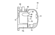
- FIG. 14 is a view corresponding to FIG. 4 of the oil separator according to the sixth modification.
- FIG. 15 is a longitudinal cross-sectional view of a compressor according to Modified Example 7, in which the periphery of the oil separator is enlarged.
- FIG. 16 is a view corresponding to FIG. 8 in another embodiment.
- Embodiment The oil separator (40) according to the embodiment is also used as a compressor (10).
- the compressor (10) is connected to the refrigerant circuit of the refrigeration system. In the refrigerant circuit, a refrigeration cycle is performed by circulating the refrigerant compressed by the compressor (10).
- the compressor (10) shown in FIG. 1 is a single screw compressor.
- the compressor (10) includes a casing (11), a motor (20) in the casing (11), a drive shaft (23), and a compression mechanism (30).
- the compressor (10) has an oil separator (40).
- the oil separator (40) is also used as a part of the casing (11).
- the casing (11) is composed of a metal-made horizontally long semi-sealed container.
- the casing (11) includes a casing body (12), a suction cover (13), and a discharge cover (41).
- the casing body (12) is formed in a horizontally long cylindrical shape.
- the suction cover (13) closes the opening at one end in the longitudinal direction (axial direction) of the casing body (12).
- the discharge cover (41) closes the opening at the other end in the longitudinal direction of the main body.
- a low pressure space (L) is formed near the suction cover (13), and a high pressure space (H) is formed near the discharge cover (41).
- a suction port (13a) is formed at the top of the suction cover (13).
- a suction pipe (not shown) is connected to the suction port (13a).
- the suction pipe is connected to the refrigerant circuit. From the suction pipe, a low pressure refrigerant is introduced into the low pressure space (L) in the casing (11).
- the discharge cover (41) is also used as the oil separator (40). Details of the discharge cover (41) will be described later.
- the motor (20) is disposed in the low pressure space (L).
- the motor (20) includes a stator (21) fixed to the casing body (12), and a rotor (22) disposed inside the stator (21).
- a drive shaft (23) is fixed at the center of the rotor (22).
- the motor (20) is configured to be variable in rotational speed or capacity. That is, the motor (20) is an inverter type to which power is supplied via the inverter device.
- the drive shaft (23) is connected to the motor (20) and the compression mechanism (30).
- the drive shaft (23) extends horizontally along the longitudinal direction of the casing (11).
- the drive shaft (23) is rotatably supported by the first bearing (24) and the second bearing (25).
- the first bearing (24) is disposed inside the suction cover (13).
- the second bearing (25) is disposed in the bearing chamber (26).
- the bearing chamber (26) is provided at the center of the inside of the casing body (12).
- the compression mechanism (30) is driven by the motor (20) via the drive shaft (23).
- the compression mechanism (30) includes a cylinder portion (31), a screw rotor (32), and two gate rotors (not shown).
- the cylinder portion (31) is provided at the center of the inside of the casing body (12). Inside the cylinder portion (31), a slide valve (not shown) for performing an unloading operation (operation of returning a part of the compressed refrigerant to the low pressure space (L)) is provided.
- the screw rotor (32) is accommodated inside the cylinder portion (31).
- the screw rotor (32) is rotationally driven by the drive shaft (23).
- a spiral groove (33) is formed around the screw rotor (32).
- a plurality of gates of the gate rotor mesh with the spiral groove (33).
- a compression chamber (35) is formed between the cylinder portion (31), the screw rotor (32), and the gate.
- the refrigerant compressed in the compression chamber (35) is discharged from the discharge port (36) to the discharge passage (37) around the cylinder portion (31).
- a disk-like partition (15) is formed between the compression mechanism (30) and the high pressure space (H).
- the outer peripheral surface of the partition portion (15) is fixed to the inner peripheral surface of the casing main body (12).
- a discharge communication hole (16) for communicating the discharge passage (37) with the high pressure space (H) is formed in the partition portion (15). The refrigerant in the discharge passage (37) is sent to the high pressure space (H) through the discharge communication hole (16).
- An oil introduction passage (17) is formed in the partition portion (15).
- the oil introduction passage (17) brings the first oil reservoir (18) in the lower part of the high pressure space (H) into communication with the bearing chamber (26).
- the oil separator (40) separates oil from the refrigerant in the high pressure space (H).
- the oil separator (40) is a centrifugal type that separates oil using centrifugal force. Strictly speaking, the oil separator (40) is a cyclone type that separates the oil in the refrigerant by the swirling flow between the outer cylinder (71) and the inner cylinder (82).
- the oil separator (40) includes a discharge cover (41), an inflow pipe (50), a separator body (70), and an inner member (80).
- the discharge cover (41) doubles as a part of the above-mentioned casing (11).
- the inflow pipe (50) introduces the high pressure refrigerant in the high pressure space (H) into the separator body (70).
- the separator body (70) is formed in a bottomed cylindrical shape.
- the peripheral wall of the separator body (70) constitutes an outer cylinder (71).
- the inner member (80) is attached to the top of the separator body (70).
- the inner member (80) has a top plate (81) closing the upper side of the separator body (70) and an inner cylinder (82) disposed inside the separator body (70).
- the discharge cover (41) includes a discharge cover main body (42) and a flange (43).
- the discharge cover main body (42) is formed in a rectangular cylindrical shape.
- a cover opening (44) is formed in the discharge cover main body (42) on the side surface facing the casing main body (12).
- a first internal space (45) for separating oil is formed inside the discharge cover body (42).
- the first inner space (45) constitutes a part of the high pressure space (H). That is, the first internal space (45) constitutes a part of the first oil reservoir (18).
- the flange (43) projects radially outward from the outer edge of the cover opening (44).
- the flange (43) is formed in a rectangular frame shape.
- the flange (43) is connected to the casing body (12) via a fastening member (not shown). As a result, the casing body (12) is closed by the discharge cover (41) to form an integral casing (11).
- An inflow tube (50) is provided at the top of the separator body (70). More precisely, the height position of the inflow pipe (50) is higher than the lower end of the inner cylinder (82) (see FIG. 4).
- the inflow tube (50) includes a straight portion (51) and a curved portion (60). The straight portion (51) is formed on the upstream side of the inflow pipe (50), and the curved portion (60) is formed on the downstream side of the inflow pipe (50).
- the straight portion (51) is located inside the discharge cover main body (42).
- the straight portion (51) extends horizontally along the axis of the casing (11).
- the inflow end of the straight portion (51) i.e., the inlet (51a) of the inflow tube (50) faces the high pressure space (H).
- the inlet (51a) is formed substantially flush with the end face of the flange (43).
- the curved portion (60) has a function of separating the oil in the refrigerant flowing into the inflow pipe (50) by centrifugal force.
- the curved portion (60) of the present embodiment is formed outside the separator body (70).
- the beginning of the curved portion (60) is continuous with the straight portion (51).
- the curved portion (60) is curved around the axis of the separator body (70). More precisely, the curved portion (60) is curved in the same direction as the rotational flow of the swirling flow inside the separator body (70) from its upstream portion to its downstream portion.
- the curved portion (60) is curved along the outer cylinder (71) of the separator body (70) or so as to surround the outer cylinder (71).
- the curved portion (60) is curved so as to surround the outer cylinder (71) of the separator body (70).
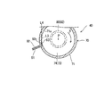
- the outflow end (60a) of the curved portion (60) opens into the second internal space (73) of the separator body (70).
- the outflow end (60a) of the curved portion (60) is directed along the tangent to the inner peripheral surface of the outer cylinder (71).
- the axis (L1) of the inflow port (51a) of the inflow pipe (50) is a separator than the tangent (L2) of the outer peripheral surface of the outer cylinder (71) of the separator body (70). Offset towards the center (P) of the body (70).
- the separator body (70) separates the oil in the refrigerant using centrifugal force generated by the swirling flow of the refrigerant.
- the separator body (70) is a vertically long, bottomed cylindrical container whose upper side is open.
- the separator body (70) has the above-mentioned outer cylinder (71) and a disk-like bottom plate (72) (bottom) that closes the lower side of the outer cylinder (71).
- a second internal space (73) is formed inside the separator body (70). At a lower portion of the second internal space (73), a second oil reservoir (74) is formed where the separated oil is stored.
- An oil discharge port (75) is formed at the lower end of the outer cylinder (71).
- the oil discharge port (75) brings the second internal space (73) (second oil reservoir (74)) into communication with the first internal space (first oil reservoir (18)). Thereby, the oil of the second oil reservoir (74) can be sent to the first oil reservoir (18) through the oil outlet (75).
- the inner member (80) has the top plate (81) and the inner cylinder (82) described above.
- the top plate (81) is formed in a disk shape in which a circular opening (83) penetrates in the thickness direction (vertical direction).
- the outer diameter of the top plate (81) is larger than the inner diameter of the separator body (70).
- the outer peripheral edge of the top plate (81) is fixed to the upper end of the separator body (70).
- the refrigerant pipe (discharge pipe) of the refrigerant circuit is connected to the circular opening (83) of the top plate (81).
- the inner cylinder (82) is formed in a cylindrical shape extending downward from the inner edge of the circular opening (83) of the top plate (81).
- the inner cylinder (82) is disposed coaxially with the outer cylinder (71).
- a cylindrical space is formed between the inner cylinder (82) and the outer cylinder (71) in which the refrigerant turns around the axis (the direction indicated by the arrow X in FIG. 5).
- An internal passage (84) through which the refrigerant flows upward is formed inside the inner cylinder (82).
- an inlet (inner cylinder inlet (85)) communicating with the second internal space (73) is formed.
- the outflow end (upper end) of the internal passage (84) communicates with the circular opening (83).
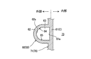
- the bending portion (60) has a first wall (61) and a second wall (62).
- the first wall (61) is positioned inward (toward the separator body (70)), and the second wall (62) is positioned outward.
- the first wall (61) is formed substantially flush with the outer cylinder (71) of the separator body (70).
- the first wall (61) and the inner surface (61a) have a flat shape extending vertically, as viewed in a cross section perpendicular to the axis of the inflow pipe (50).
- the first wall (61) is substantially arc-shaped in a cross-sectional view perpendicular to the axis of the separator body (70).
- the first wall (61) is formed over a range of about 180 ° or more, based on the axis of the separator body (70).
- the first wall (61) is also used as part of the outer cylinder (71). That is, the peripheral wall (outer cylinder (71)) of the separator main body (70) and the first wall (61) of the curved portion (60) constitute a common portion (C). In other words, the first wall (61) constitutes a partition between the passage (63) in the curved portion (60) and the internal space (second internal space (73)) of the separator body (70) ing.
- the second wall (62) bulges radially outward from the outer cylinder (71) to the first wall (61).
- the second wall (62) has a U-shape opening on the outer cylinder (71) side in a cross-sectional view perpendicular to the inflow pipe (50).
- the second wall (62) is substantially arc-shaped in a cross-sectional view perpendicular to the axis of the separator body (70).
- the second wall (62) is formed over a range of about 180 ° or more, based on the axis of the separator body (70).
- the second wall (62) is a non-shared part not shared with the separator body (70).
- the second wall (62) is located outside the separator body (70). Therefore, the second wall (62) constitutes an exposed portion exposed to the outside (atmospheric temperature atmosphere).
- the inner surface of the second wall (62) and the inner surface of the outer cylinder (71) are smoothly continuous. That is, in the cross-sectional shape perpendicular to the axis of the separator main body (70), the second wall (62) and the outer cylinder (71) constitute a smoothly continuous spiral inner wall.
- the spiral inner wall is wound from the outer end to the inner end in the same direction as the swirling flow of the refrigerant.
- the curved portion (60) is formed with an oil removal hole (90) for discharging the oil accumulated in the passage (63) inside the curved portion (60) to the outside.
- the shape of the flow passage cross section of the oil removal hole (90) is formed, for example, in a circular shape.
- the oil removal hole (90) is formed in the outer peripheral portion (64) of the curved portion (60).
- the outer peripheral side portion (64) is a portion of the tube wall of the curved portion (60) facing the axial center of the separator main body (70).
- the oil removal hole (90) is formed in the lower portion (65) of the curved portion (60).
- the lower portion (65) is a portion of the tube wall of the curved portion (60) that is lower than the axial center of the passage (63) in the curved portion (60) (a middle height position in the vertical direction) It is.
- the oil removal hole (90) is provided on the downstream end of the curved portion (60).
- the oil removal hole (90) opens in the normal direction so as to face the center of curvature of the inner peripheral surface of the curved portion (60).
- the oil removal hole (90) of the present embodiment may be one or two or more.
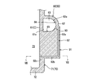
- the passage member (91) is provided at a position corresponding to the oil removal hole (90).
- the passage member (91) is formed in a vertically long rectangular parallelepiped or flat plate shape.
- An oil passage (92) communicating with the oil removal hole (90) is formed in the passage member (91).
- the oil passage (92) brings the oil removal hole (90) of the curved portion (60) into communication with the second internal space (second oil reservoir (74)) of the separator body (70).
- the oil passage (92) comprises an elongated vertical passage (92a), a horizontally elongated horizontal passage (92b) connected to the lower end of the vertical passage (92a), and an outflow passage connected to the radially inner end of the horizontal passage (92b) And (92c).
- the outflow opening (93) of the oil passage (92) is formed in the outer cylinder (71) of the separator body (70). More specifically, the outflow opening (93) of the oil passage (92) is located below the inner cylinder inlet (85) and on the outer peripheral side of the inner cylinder inlet (85).
- the axis (L3) of the outflow opening (93) of the oil passage (92) is directed along the tangent (L4) of the inner peripheral surface (71a) of the outer cylinder (71). That is, in the present embodiment, the axis (L3) of the outflow opening (93) forms a tangent (L4) of the inner peripheral surface (71a) of the outer cylinder (71) (strictly, the outflow opening (93) is formed It almost agrees with the tangent line).
- the discharge cover (41), the inflow pipe (50), the separator body (70), and the passage member (91) are integrally formed by casting. That is, the discharge cover (41), the inflow pipe (50), the separator body (70), and the passage member (91) constitute a first unit having an integral structure made of a casting.
- the inner member (80) is composed of a first unit and a second unit which is a separate member.
- the first wall (61) faces the second internal space (73) of the separator body (70),
- the wall (62) is exposed to the outside of the separator body (70).
- the second wall (62) has a temperature lower than that of the first wall (61).
- the oil drop near the relatively high temperature first wall (61) is likely to flow and to move to the second wall (62) side by centrifugal force.
- the oil near the relatively low temperature second wall (62) is cooled and becomes less likely to flow. Therefore, in the curved portion (60), the oil is easily collected in the second wall (62) to the outer peripheral portion (64), and the size of the collected oil droplet is also likely to be large.
- the oil whose oil droplet size is increased at the curved portion (60) flows into the separator body (70) together with the refrigerant.
- the refrigerant swirls in the second internal space (73).
- oil droplets in the refrigerant are further separated by centrifugal force.
- the oil droplets in the refrigerant are increased in size when passing through the above-described curved portion (60).
- the centrifugal force acting on the oil droplets is increased, and the oil separation efficiency is improved.
- the oil separated in the second internal space (73) is stored in the second oil reservoir (74). After the oil is separated, the refrigerant flows upward through the internal passage (84) and is sent to the refrigerant circuit through the discharge pipe.
- An oil removing hole (90) is formed in the above-mentioned curved portion (60). For this reason, a part of the oil separated at the curved portion (60) can be sent directly to the second oil sump (74) through the oil drain hole (90) and the oil passage (92).
- the oil removal hole (90) is formed in the outer peripheral portion (64) of the curved portion (60).
- oil droplets moved by centrifugal force are easily accumulated in the outer peripheral side portion (64). Therefore, the oil collected on the inner wall of the outer peripheral side portion (64) can be easily introduced to the oil drain hole (90).
- the oil removal hole (90) is formed in the lower portion (65) of the curved portion (60). Therefore, the oil accumulated on the inner wall of the lower portion (65) by its own weight can be easily led to the oil drain hole (90).
- the outflow opening (93) of the oil passage (92) is formed in the outer cylinder (71). Therefore, a sufficient distance can be secured between the outflow opening (93) and the inflow end of the internal passage (84). Further, as shown in FIG. 8, since the outflow opening (93) (axis (L3)) is directed to the tangential line (L4) direction of the outer cylinder (71), the oil which has flowed out from the outflow opening (93) Flows into the second internal space (73) along the inner peripheral surface of the outer cylinder (71). As a result, the oil flowing from the oil passage (92) into the second internal space (73) can be prevented from being sent to the discharge pipe together with the refrigerant on the flow of the refrigerant toward the internal passage (84).
- the oil of the second oil sump (74) is sent to the first oil sump (18) via the oil outlet (75).
- the oil of the first oil reservoir (18) is sent to the bearing chamber (26) via the oil introduction passage (17).
- the oil in the bearing chamber (26) lubricates the sliding portion of the second bearing (25).
- the oil in the bearing chamber (26) is also supplied to the sliding portion of the compression mechanism (30) and the first bearing (24) via a predetermined passage (not shown).
- the outer cylinder (71) (peripheral wall) of the separator body (70) and the inflow pipe (50) have the first wall (61) (sharing portion (C)) shared with each other.
- the oil separator (40) can be miniaturized radially inward by sharing the curved portion (60) and the outer cylinder (71).
- the separator body (70) side tends to be hotter .
- oil droplets can be collected on the second wall (62) or the outer peripheral portion (64) of the curved portion (60), and the aggregation of oil can be promoted.
- the first wall (61) is formed substantially flush with the outer cylinder (71) (non-sharing portion) of the separator body (70). For this reason, simplification of the shape of an outer cylinder (71) can be achieved, and shaping
- the shape of the cross section perpendicular to the axis of the inner surface (61a) of the first wall (61) is flat. For this reason, the cross-sectional area of the passage (63) of the bending portion (60) can be gained. Therefore, the outer diameter (pipe diameter) of the curved portion (60) can be reduced, and the oil separator (40) can be miniaturized.
- the curved portion (60) includes a second wall (62) which bulges radially outward from the peripheral wall (71) of the separator body (70). This increases the surface area of the second wall (62) exposed to the outside (atmosphere) of the separator body (70). Therefore, by promoting the cooling of the oil on the second wall (62) side, the oil is easily collected on the inner surface of the second wall (62).
- the axis (L1) of the inlet (51a) of the inflow pipe (50) is the axis (A) of the axis (Y) of the separator body (70) than the tangent (L2) of the outer peripheral surface of the separator body (70). Offset towards the center (P)).
- the position of the inflow port (51a) of the inflow pipe (50) is located closer to the center (P) than both radial ends of the separator body (70). Therefore, the installation space of the inflow pipe (50) can be reduced, and the width of the discharge cover (41) can be shortened.
- this configuration allows the overall length of the curved portion (60) to be increased. As a result, the oil separation efficiency at the curved portion (60) can be improved.
- the separator body (70) and the inflow pipe (50) have an integral structure made of castings, obtaining the first wall (61) (shared portion (C)) while easily forming them Can.
- the casting has a relatively high vibration damping effect, the generation of vibrations and noise in the inflow pipe (50) can be suppressed.
- the oil separator (40) can be miniaturized by integrating the separator body (70), the inflow pipe (50), and the discharge cover (41), as well as generating vibration and noise. It can be suppressed.
- the oil removal hole (90) is formed in the curved portion (60), so that the oil separated by the curved portion (60) can be discharged to the outside of the curved portion (60).
- the oil can be sent to the oil removal hole (90) by using a centrifugal force acting on the oil. Therefore, the oil can be transported without using a transport source for transporting the oil or a differential pressure.
- the oil passage (92) and the passage member (91) can be shortened. It is also possible to suppress the oil from flowing out to the discharge pipe.
- the oil separator (40) can be miniaturized by integrating the separator body (70), the inflow pipe (50), and the passage member (91).
- the oil separator (40) constitutes a part of the casing (11).
- the compressor (10) can be miniaturized.
- Modified Example 1 The modification 1 shown in FIG. 9 is different from the above embodiment in the configuration of the bending portion (60).
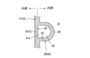
- the curved portion (60) of Modification 1 bulges radially inward from the first wall (61) which does not have the second wall (62) and is the outer cylinder (71) or the shared portion (C).
- a part of the bending portion (60) is positioned closer to the center of the separator body (70) than the outer cylinder (71). For this reason, since the curved portion (60) does not protrude radially outward with respect to the separator body (70), the size of the oil separator (40) in the radial direction can be reduced.
- the modification 2 shown in FIG. 10 is different from the above embodiment in the configuration of the bending portion (60).
- the curved portion (60) of the modification 2 does not have the first wall (61), and the second wall (62) bulges radially outward from the outer cylinder (71), and from the outer cylinder (71).
- the third wall (66) bulges radially inward.
- one or both of the second wall (62) and the third wall (66) can be regarded as the shared portion (C) of the curved portion (60) and the outer cylinder (71).
- the third modification shown in FIG. 11 is different from the above embodiment in the shape of the second wall (62).
- the inner surface (62a) of the second wall (62) of the third modification has a tapered shape as it goes radially outward in a cross-sectional view perpendicular to the axis.
- the curved portion (60) of the third modification has a polygonal (pentagonal in this example) cross-sectional shape.
- the distance between the two outboard surfaces (62b, 62b) becomes narrower as it goes radially outward.
- a groove (67) for capturing oil is formed at the radially outward tip.
- oil removal hole (90) described above may be formed in the groove (67) of the curved portion (60) of the third modification. Thus, the oil flowing through the groove (67) can flow into the oil drain hole (90).
- the curved portion (60) of Modification 4 shown in FIG. 12 has a triangular cross-sectional shape. Similar to the third modification, the inner surface (61a) of the second wall (62) of the curved portion (60) has a tapered shape as it goes radially outward in a cross-sectional view perpendicular to the axis. In the second wall (62), the distance between the two outboard surfaces (62b, 62b) becomes narrower as it goes radially outward. As a result, in the second wall (62), a groove (67) for capturing oil is formed at the radially outward tip.
- oil removal hole (90) described above may be formed in the groove (67) of the curved portion (60) of the fourth modification. Thus, the oil flowing through the groove (67) can flow into the oil drain hole (90).
- the modification 5 shown in FIG. 13 differs in the structure of an oil separator (40) from the said embodiment.
- the oil separator (40) of the fifth modification does not have the discharge cover (41) which is also used as the casing (11) of the compressor (10).
- a piping flange (52) connectable to other piping is formed.
- the piping flange (52) is connected to an outflow pipe (not shown) through which the refrigerant discharged from the compression mechanism (30) flows out.
- An oil outlet (75) is formed in the separator body (70) of the fifth modification as in the above embodiment.
- the oil outlet (75) is directly connected to a pipe for sending the oil to a predetermined supply destination.
- the modification 6 shown in FIG. 14 is provided with a separating plate (76) inside the separating body (70).
- the separation plate (76) is formed in a substantially truncated cone cylindrical shape whose internal diameter decreases downward.
- the upper end of the separation plate (76) is supported by the outer cylinder (71).
- a circular opening is formed at the lower end of the separating plate (76).
- the separation plate (76) prevents the oil of the second oil reservoir (74) from flowing into the inner cylinder (82).
- the outflow opening (93) of the oil passage (92) is located below the separating plate (76). As a result, the oil flowing out of the outflow opening (93) can be prevented from flowing into the inside of the inner cylinder (82).
- the oil separator (40) is accommodated inside the casing (11) of the compressor (10).
- the oil separator (40) is housed inside the discharge cover (14) of the casing (11).
- the discharge cover (14) is configured separately from the oil separator (40), and closes the high pressure side opening of the casing main body (11) described above.
- a high pressure space (H) filled with a high pressure refrigerant is formed in the discharge cover (14).
- An oil reservoir (14a) is formed under the discharge cover (14).
- the oil separator (40) is supported on the upper side of the oil sump (14a) by, for example, a support member (15).
- the high-pressure refrigerant compressed by the compression mechanism (30) flows through the curved portion (60) of the inflow pipe (50) and then flows into the separator body (70) as in the above-described embodiments.
- the fluid inside the separator body (70) is sent to the refrigerant circuit via the discharge pipe (85).
- the oil removal hole (90) is formed in the curved portion (60) as in the above embodiment.
- the oil removal hole (90) directly brings the inside of the curved portion (60) into communication with the outside of the curved portion (60). For this reason, the oil having flowed out of the oil draining hole (90) of the curved portion (60) falls downward by its own weight and is directly recovered to the oil sump (14a).
- the oil of the oil reservoir (14a) is used for lubricating the compression mechanism (30) and the bearings (24, 25) via a predetermined oil introduction passage as in the above embodiment.
- the oil removal hole (90) of the curved portion (60) may adopt any of the configurations of the above-described embodiments.
- the axis (L3) of the outflow opening (93) of the oil passage (92) may not coincide with the tangent (L4) of the inner peripheral surface (71a) of the outer cylinder (71) .
- the outflow opening (93) may open in the direction along the tangent (L4), while the axis (L3) may be offset to the center (P) side with respect to the tangent (L4).
- the outflow opening (93) may be opened in the normal direction so as to face the center (P).
- the oil separator (40) may have a common part (C) in which the straight part (51) of the inflow pipe (50) and the separator body (70) are mutually shared. Also in this configuration, the oil separator (40) can be miniaturized because the separator body (70) and a part of the inflow pipe (50) are used in common.
- the oil separator (40) may be of any configuration as long as it is a centrifugal type that uses centrifugal force to separate oil inside the separator body (70), and does not have the inner cylinder (82). May be
- the oil collected in the second oil reservoir (74) may be sent directly to the bearing chamber (26), or supplied to sliding parts such as the compression mechanism (30) without passing through the bearing chamber (26). You may The oil of the second oil reservoir (74) may be returned to the middle of compression (intermediate pressure portion) of the compression chamber (35).
- the oil removed from the oil removal hole (90) may be sent directly to the bearing chamber (26), or the sliding portion such as the compression mechanism (30) without passing through the bearing chamber (26) It may be supplied to The oil removed from the oil removal hole (90) may be returned to the middle of compression (intermediate pressure part) of the compression chamber (35).
- the compressor (10) may be a twin screw compressor having two screws, or may be a single gate single screw compressor having one gate rotor.
- the compressor (10) can adopt other methods such as a rotary type, a swing type, a scroll type, and a turbo type besides the screw type.
- the refrigeration system may be an air conditioning system that air-conditions the room, a cooler that cools the air in the storage, a heat pump water heater, or the like.
- the oil separator (40) may be applied to devices other than the compressor (10) and the refrigeration device if the oil separator is used to separate oil from fluid.
- the invention is useful with centrifugal oil separators.
Abstract
分離器本体(70)の周壁(71)と、流入管(50)とは、互いに共有される共有部(C)を有する。
Description
本発明は、遠心分離式の油分離器に関する。
特許文献1に開示される油分離器では、流入管に湾曲部が形成されている。湾曲部では、流体中の油が遠心力によって分離される。その後、流体は分離器本体に流入する。分離器本体では、旋回流に伴う遠心力により、流体中の油が更に分離される(例えば特許文献1の図3を参照)。
流入管に湾曲部を形成すると、油分離器を設置するスペースが大きくなる。
本発明は、流入管に湾曲部を有する油分離器の小型化を図ることを目的とする。
第1の態様は、遠心分離式の油分離器であって、筒状の分離器本体(70)と、油を含む流体を前記分離器本体(70)に導入するとともに湾曲部(60)を有する流入管(50)とを備え、前記分離器本体(70)の周壁(71)と、前記流入管(50)とは、互いに共有される共有部(C)を有することを特徴とする油分離器である。
第1の態様では、分離器本体(70)と流入管(50)とが共有部(C)を有するため、油分離器(40)の小型化を図ることができる。
第2の態様は、第1の態様において、前記共有部(C)は、前記流入管(50)の前記湾曲部(60)に設けられることを特徴とする油分離器である。
第2の態様では、比較的設置スペースが大きい湾曲部(60)に共有部(C)を設けることで、油分離器(40)を小型化できる。
第3の態様は、第2の態様において、前記湾曲部(60)は、前記分離器本体(70)の周壁(71)と略面一に形成される、前記共有部(C)としての第1壁(61)を含んでいることを特徴とする油分離器である。
第3の態様では、分離器本体(70)の周壁(71)の形状の簡素化が図られる。
第4の態様は、第3の態様において、前記第1壁(61)の内面(61a)の軸直角断面の形状は、平坦であることを特徴とする油分離器である。
第4の態様では、湾曲部(60)の通路断面積を稼ぐことができるので、湾曲部(60)の配管径(直径)を小さくできる。
第5の態様は、第2乃至4の態様のいずれか1つにおいて、前記湾曲部(60)は、前記分離器本体(70)の周壁(71)から径方向外方へ膨出する第2壁(62)を含んでいることを特徴とする油分離器である。
第5の態様では、湾曲部(60)が外部に露出する表面積が大きくなる。
第6の態様は、第2乃至5の態様のいずれか1つにおいて、前記湾曲部(60)は、前記分離器本体(70)の周壁(71)から径方向内方へ膨出する第3壁(66)を含んでいることを特徴とする油分離器である。
第6の態様では、湾曲部(60)の一部が分離器本体(70)の内部に位置するため、湾曲部(60)の全体としての径方向のサイズを小さくできる。
第7の態様は、第2乃至6の態様のいずれか1つにおいて、前記流入管(50)の流入口(51a)の軸線L1は、前記分離器本体(70)の外周面の接線L2によりも該分離器本体(70)の中心に向かってオフセットしていることを特徴とする油分離器である。
第7の態様では、油分離器(40)の全体のサイズを小さくできるとともに、湾曲部(60)の全長を長くできる。
第8の態様は、第1乃至7の態様のいずれか1つにおいて、前記分離器本体(70)と前記流入管(50)は、鋳物からなる一体構造であることを特徴とする油分離器である。
第8の態様では、共有部(C)を有する一体構造を容易に成形できる。
第9の態様は、第1乃至8の態様のいずれか1つにおいて、前記前記湾曲部(60)は、径方向外方に向かうにつれて先細な形状の内面(61a)を有していることを特徴とする油分離器である。
第9の態様では、遠心力を利用して分離した油を、湾曲部(60)の先細な内面(61a)において捕集することができる。
第10の態様は、第1乃至9の態様のいずれか1つにおいて、前記湾曲部(60)には、油抜き穴(90)が形成されることを特徴とする油分離器である。
第10の態様では、湾曲部(60)の油を油抜き穴(90)を通じて湾曲部(60)の外部へ排出できる。
第11の態様は、第10の態様において、前記油抜き穴(90)と連通する油通路(92)を形成する通路部材(91)を備え、前記通路部材(91)は、前記湾曲部(60)及び前記分離器本体(70)の少なくとも一方と一体構造であることを特徴とする油分離器である。
第11の態様では、通路部材(91)を有する油分離器の小型化を図ることができる。
第12の態様は、流体を圧縮する圧縮機構(30)と、前記圧縮機構(30)から吐出された流体を対象とする、第1乃至11の態様のいずれか1つに記載の油分離器(40)とを備えていることを特徴とする圧縮機である。
第12の態様では、油分離器(40)を有する圧縮機を小型化できる。
第13の態様は、第12の態様において、前記圧縮機構(30)を収容するケーシング(11)を備え、前記油分離器(40)が、前記ケーシング(11)の一部を構成していることを特徴とする圧縮機である。
第13の態様では、圧縮機の小型化を図ることができる。
以下、本発明の実施形態について図面を参照しながら説明する。なお、以下の実施形態は、本質的に好ましい例示であって、本発明、その適用物、あるいはその用途の範囲を制限することを意図するものではない。また、以下に説明する各実施形態、変形例、その他の例等の各構成は、本発明を実施可能な範囲において、組み合わせたり、一部を置換したりできる。
《実施形態》
実施形態に係る油分離器(40)は、圧縮機(10)に兼用されている。圧縮機(10)は、冷凍装置の冷媒回路に接続される。冷媒回路では、圧縮機(10)で圧縮された冷媒が循環することで冷凍サイクルが行われる。
実施形態に係る油分離器(40)は、圧縮機(10)に兼用されている。圧縮機(10)は、冷凍装置の冷媒回路に接続される。冷媒回路では、圧縮機(10)で圧縮された冷媒が循環することで冷凍サイクルが行われる。
図1に示す圧縮機(10)は、シングルスクリュー圧縮機である。圧縮機(10)は、ケーシング(11)と、該ケーシング(11)内の電動機(20)、駆動軸(23)、及び圧縮機構(30)を備えている。圧縮機(10)は、油分離器(40)を有している。油分離器(40)は、ケーシング(11)の一部として兼用されている。
〈ケーシング〉
ケーシング(11)は、金属製の横長の半密閉容器で構成される。ケーシング(11)は、ケーシング本体(12)、吸入カバー(13)、及び吐出カバー(41)を備えている。ケーシング本体(12)は、横長の筒状に形成される。吸入カバー(13)は、ケーシング本体(12)の長手方向(軸方向)の一端の開口を閉塞する。吐出カバー(41)は、本体の長手方向の他端の開口を閉塞する。ケーシング(11)の内部には、吸入カバー(13)寄りに低圧空間(L)が形成され、吐出カバー(41)寄りに高圧空間(H)が形成される。
ケーシング(11)は、金属製の横長の半密閉容器で構成される。ケーシング(11)は、ケーシング本体(12)、吸入カバー(13)、及び吐出カバー(41)を備えている。ケーシング本体(12)は、横長の筒状に形成される。吸入カバー(13)は、ケーシング本体(12)の長手方向(軸方向)の一端の開口を閉塞する。吐出カバー(41)は、本体の長手方向の他端の開口を閉塞する。ケーシング(11)の内部には、吸入カバー(13)寄りに低圧空間(L)が形成され、吐出カバー(41)寄りに高圧空間(H)が形成される。
吸入カバー(13)の上部には、吸入口(13a)が形成される。吸入口(13a)には、吸入管(図示省略)が接続される。吸入管は、冷媒回路に接続される。吸入管からは、ケーシング(11)内の低圧空間(L)に低圧の冷媒が導入される。吐出カバー(41)は、油分離器(40)に兼用される。吐出カバー(41)の詳細は後述する。
〈電動機〉
電動機(20)は、低圧空間(L)に配置される。電動機(20)は、ケーシング本体(12)に固定されるステータ(21)と、該ステータ(21)の内部に配置されるロータ(22)とを備えている。ロータ(22)の中心部には駆動軸(23)が固定される。電動機(20)は、回転数ないし容量が可変に構成される。つまり、電動機(20)は、インバータ装置を介して電力が供給されるインバータ式である。
電動機(20)は、低圧空間(L)に配置される。電動機(20)は、ケーシング本体(12)に固定されるステータ(21)と、該ステータ(21)の内部に配置されるロータ(22)とを備えている。ロータ(22)の中心部には駆動軸(23)が固定される。電動機(20)は、回転数ないし容量が可変に構成される。つまり、電動機(20)は、インバータ装置を介して電力が供給されるインバータ式である。
〈駆動軸〉
駆動軸(23)は、電動機(20)及び圧縮機構(30)に連結している。駆動軸(23)は、ケーシング(11)の長手方向に沿って水平に延びている。駆動軸(23)は、第1軸受け(24)と第2軸受け(25)とに回転可能に支持される。第1軸受け(24)は、吸入カバー(13)の内部に配置される。第2軸受け(25)は、軸受け室(26)に配置される。軸受け室(26)は、ケーシング本体(12)の内部中央に設けられる。
駆動軸(23)は、電動機(20)及び圧縮機構(30)に連結している。駆動軸(23)は、ケーシング(11)の長手方向に沿って水平に延びている。駆動軸(23)は、第1軸受け(24)と第2軸受け(25)とに回転可能に支持される。第1軸受け(24)は、吸入カバー(13)の内部に配置される。第2軸受け(25)は、軸受け室(26)に配置される。軸受け室(26)は、ケーシング本体(12)の内部中央に設けられる。
〈圧縮機構〉
圧縮機構(30)は、駆動軸(23)を介して電動機(20)に駆動される。圧縮機構(30)では、冷媒が圧縮される。圧縮機構(30)は、シリンダ部(31)、スクリューロータ(32)、及び2つのゲートロータ(図示省略)を備えている。シリンダ部(31)は、ケーシング本体(12)の内部中央に設けられる。シリンダ部(31)の内部には、アンロード動作(圧縮した冷媒の一部を低圧空間(L)に戻す動作)を行うためのスライドバルブ(図示省略)が設けられる。スクリューロータ(32)は、シリンダ部(31)の内部に収容されている。スクリューロータ(32)は、駆動軸(23)によって回転駆動される。スクリューロータ(32)の周囲には螺旋溝(33)が形成される。螺旋溝(33)には、ゲートロータの複数のゲートが歯合する。これにより、シリンダ部(31)、スクリューロータ(32)、及びゲートの間に、圧縮室(35)が形成される。圧縮室(35)で圧縮された冷媒は、吐出ポート(36)からシリンダ部(31)の周囲の吐出通路(37)に吐出される。
圧縮機構(30)は、駆動軸(23)を介して電動機(20)に駆動される。圧縮機構(30)では、冷媒が圧縮される。圧縮機構(30)は、シリンダ部(31)、スクリューロータ(32)、及び2つのゲートロータ(図示省略)を備えている。シリンダ部(31)は、ケーシング本体(12)の内部中央に設けられる。シリンダ部(31)の内部には、アンロード動作(圧縮した冷媒の一部を低圧空間(L)に戻す動作)を行うためのスライドバルブ(図示省略)が設けられる。スクリューロータ(32)は、シリンダ部(31)の内部に収容されている。スクリューロータ(32)は、駆動軸(23)によって回転駆動される。スクリューロータ(32)の周囲には螺旋溝(33)が形成される。螺旋溝(33)には、ゲートロータの複数のゲートが歯合する。これにより、シリンダ部(31)、スクリューロータ(32)、及びゲートの間に、圧縮室(35)が形成される。圧縮室(35)で圧縮された冷媒は、吐出ポート(36)からシリンダ部(31)の周囲の吐出通路(37)に吐出される。
〈隔壁〉
圧縮機構(30)と高圧空間(H)の間には、円板状の仕切部(15)が形成される。仕切部(15)の外周面は、ケーシング本体(12)の内周面に固定される。仕切部(15)には、吐出通路(37)と高圧空間(H)とを連通させる吐出連通穴(16)が形成される。吐出通路(37)の冷媒は、吐出連通穴(16)を通過して高圧空間(H)に送られる。
圧縮機構(30)と高圧空間(H)の間には、円板状の仕切部(15)が形成される。仕切部(15)の外周面は、ケーシング本体(12)の内周面に固定される。仕切部(15)には、吐出通路(37)と高圧空間(H)とを連通させる吐出連通穴(16)が形成される。吐出通路(37)の冷媒は、吐出連通穴(16)を通過して高圧空間(H)に送られる。
仕切部(15)には、油導入路(17)が形成される。油導入路(17)は、高圧空間(H)の下部の第1油溜まり(18)と、軸受け室(26)とを連通させる。
〈油分離器の全体構成〉
次いで油分離器(40)の構成について、図1~図8を参照しながら詳細に説明する。油分離器(40)は、高圧空間(H)の冷媒中から油を分離する。油分離器(40)は、遠心力を利用して油を分離する遠心分離式である。厳密にいうと、油分離器(40)は、外筒(71)と内筒(82)との間の旋回流によって冷媒中の油を分離する、サイクロン式である。
次いで油分離器(40)の構成について、図1~図8を参照しながら詳細に説明する。油分離器(40)は、高圧空間(H)の冷媒中から油を分離する。油分離器(40)は、遠心力を利用して油を分離する遠心分離式である。厳密にいうと、油分離器(40)は、外筒(71)と内筒(82)との間の旋回流によって冷媒中の油を分離する、サイクロン式である。
油分離器(40)は、吐出カバー(41)と、流入管(50)と、分離器本体(70)と、内部材(80)とを備えている。吐出カバー(41)は、上述したケーシング(11)の一部を兼用している。流入管(50)は、高圧空間(H)の高圧冷媒を分離器本体(70)に導入する。分離器本体(70)は、有底筒状に形成される。分離器本体(70)の周壁は、外筒(71)を構成している。内部材(80)は、分離器本体(70)の上部に取り付けられる。内部材(80)は、分離器本体(70)の上側を閉塞する天板(81)と、分離器本体(70)の内部に配置される内筒(82)とを有している。
〈吐出カバー〉
図2及び図3に示すように、吐出カバー(41)は、吐出カバー本体(42)と、フランジ(43)とを備えている。吐出カバー本体(42)は、角形筒状に形成される。吐出カバー本体(42)には、ケーシング本体(12)を向く側面にカバー開口(44)が形成される。吐出カバー本体(42)の内部には、油を分離するための第1内部空間(45)が形成される。第1内部空間(45)は、高圧空間(H)の一部を構成している。つまり、第1内部空間(45)は、第1油溜まり(18)の一部を構成している。
図2及び図3に示すように、吐出カバー(41)は、吐出カバー本体(42)と、フランジ(43)とを備えている。吐出カバー本体(42)は、角形筒状に形成される。吐出カバー本体(42)には、ケーシング本体(12)を向く側面にカバー開口(44)が形成される。吐出カバー本体(42)の内部には、油を分離するための第1内部空間(45)が形成される。第1内部空間(45)は、高圧空間(H)の一部を構成している。つまり、第1内部空間(45)は、第1油溜まり(18)の一部を構成している。
フランジ(43)は、カバー開口(44)の外縁から径方向外方へ張り出している。フランジ(43)は、矩形枠状に形成される。フランジ(43)は、締結部材(図示省略)を介してケーシング本体(12)に連結される。これにより、ケーシング本体(12)が吐出カバー(41)によって閉塞され、一体的なケーシング(11)が構成される。
〈流入管〉
流入管(50)は、分離器本体(70)の上部に設けられる。より厳密には、流入管(50)の高さ位置は、内筒(82)の下端よりも高い(図4を参照)。流入管(50)は、直線部(51)と湾曲部(60)とを含んでいる。直線部(51)は、流入管(50)の上流側に形成され、湾曲部(60)は流入管(50)の下流側に形成される。
流入管(50)は、分離器本体(70)の上部に設けられる。より厳密には、流入管(50)の高さ位置は、内筒(82)の下端よりも高い(図4を参照)。流入管(50)は、直線部(51)と湾曲部(60)とを含んでいる。直線部(51)は、流入管(50)の上流側に形成され、湾曲部(60)は流入管(50)の下流側に形成される。
図3に示すように、直線部(51)は、吐出カバー本体(42)の内部に位置している。直線部(51)は、ケーシング(11)の軸心に沿うように水平に延びている。直線部(51)の流入端(即ち、流入管(50)の流入口(51a))は高圧空間(H)に面している。流入口(51a)は、フランジ(43)の端面と略面一に形成される。
湾曲部(60)は、流入管(50)に流入した冷媒中の油を遠心力によって分離する機能を有する。本実施形態の湾曲部(60)は、分離器本体(70)の外部に形成される。湾曲部(60)の始端は、直線部(51)と連続している。湾曲部(60)は、分離器本体(70)の軸周り方向に湾曲している。より厳密には、湾曲部(60)は、その上流部から下流部に向かって、分離器本体(70)の内部の旋回流の回転方向と同じ方向に湾曲している。湾曲部(60)は、分離器本体(70)の外筒(71)に沿うように、あるいは該外筒(71)を囲むように湾曲している。湾曲部(60)は、分離器本体(70)の外筒(71)を囲むように湾曲している。
図5に示すように、湾曲部(60)の流出端(60a)は、分離器本体(70)の第2内部空間(73)に開口している。湾曲部(60)の流出端(60a)は、外筒(71)の内周面の接線に沿った方向を向いている。
図5に示すように、流入管(50)の流入口(51a)の軸線(L1)は、分離器本体(70)の外筒(71)の外周面の接線(L2)よりも、分離器本体(70)の中心(P)に向かってオフセットしている。
〈分離器本体〉
分離器本体(70)は、冷媒の旋回流により生じる遠心力を利用して、冷媒中の油を分離する。分離器本体(70)は、上側が開放する縦長の有底円筒状の容器である。分離器本体(70)は、上述した外筒(71)と、該外筒(71)の下側を閉塞する円板状の底板(72)(底部)とを有する。分離器本体(70)の内部には、第2内部空間(73)が形成される。第2内部空間(73)の下部には、分離された油が貯留される第2油溜まり(74)が形成される。
分離器本体(70)は、冷媒の旋回流により生じる遠心力を利用して、冷媒中の油を分離する。分離器本体(70)は、上側が開放する縦長の有底円筒状の容器である。分離器本体(70)は、上述した外筒(71)と、該外筒(71)の下側を閉塞する円板状の底板(72)(底部)とを有する。分離器本体(70)の内部には、第2内部空間(73)が形成される。第2内部空間(73)の下部には、分離された油が貯留される第2油溜まり(74)が形成される。
外筒(71)の下端部には、油排出口(75)が形成される。油排出口(75)は、第2内部空間(73)(第2油溜まり(74))と、第1内部空間(第1油溜まり(18))とを連通させる。これにより、第2油溜まり(74)の油を、油排出口(75)を介して第1油溜まり(18)へ送ることができる。
〈内部材〉
内部材(80)は、上述した天板(81)及び内筒(82)を有している。
内部材(80)は、上述した天板(81)及び内筒(82)を有している。
天板(81)は、円形開口(83)が板厚方向(鉛直方向)に貫通する円板状に形成される。天板(81)の外径は、分離器本体(70)の内径よりも大きい。天板(81)の外周縁部は、分離器本体(70)の上端に固定される。天板(81)の円形開口(83)には、冷媒回路の冷媒配管(吐出管)が接続される。
内筒(82)は、天板(81)の円形開口(83)の内縁から下方に延びる円筒状に形成される。内筒(82)は、外筒(71)と同軸上に配置される。これにより、内筒(82)と外筒(71)との間には、冷媒が軸周り(図5の矢印Xで示す方向)に旋回する円筒状の空間が形成される。内筒(82)の内部には、冷媒が上方に流れる内部通路(84)が形成される。内部通路(84)の流入端(下端)には、第2内部空間(73)に連通する流入口(内筒流入口(85))が形成される。内部通路(84)の流出端(上端)は、円形開口(83)に連通する。
〈湾曲部の詳細〉
流入管(50)の湾曲部(60)の詳細な構成について説明する。
流入管(50)の湾曲部(60)の詳細な構成について説明する。
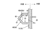
図5及び図6に示すように、湾曲部(60)は、第1壁(61)と第2壁(62)とを有する。第1壁(61)が内側寄り(分離器本体(70)寄り)に位置し、第2壁(62)が外側寄りに位置している。
第1壁(61)は、分離器本体(70)の外筒(71)と略面一に形成される。第1壁(61)、及びその内面(61a)は、流入管(50)の軸直角断面視において、上下に延びる平坦形状である。第1壁(61)は、分離器本体(70)の軸直角断面視において、略円弧状である。第1壁(61)は、分離器本体(70)の軸心を基準とした場合に、約180°以上の範囲に亘って形成される。
第1壁(61)は、外筒(71)の一部として兼用されている。つまり、分離器本体(70)の周壁(外筒(71))と湾曲部(60)の第1壁(61)とが、共有部(C)を構成している。換言すると、第1壁(61)は、湾曲部(60)内の通路(63)と、分離器本体(70)の内部空間(第2内部空間(73))との間の隔壁を構成している。
第2壁(62)は、外筒(71)ないし第1壁(61)から径方向外方へ膨出している。第2壁(62)は、流入管(50)の軸直角断面視において、外筒(71)側に開口するU字形状である。第2壁(62)は、分離器本体(70)の軸直角断面視において、略円弧状である。第2壁(62)は、分離器本体(70)の軸心を基準とした場合に、約180°以上の範囲に亘って形成される。
第2壁(62)は、分離器本体(70)と共有されない非共有部である。第2壁(62)は、分離器本体(70)の外部に位置している。従って、第2壁(62)は、外部(大気温度雰囲気)に露出される露出部を構成している。
図5に示すように、第2壁(62)の内面と外筒(71)の内面とは、滑らかに連続している。つまり、分離器本体(70)の軸直角な断面形状において、第2壁(62)と外筒(71)とは、滑らかに連続する渦巻き状の内壁を構成している。この渦巻き状の内壁は、その外端から内端へ向かって、冷媒の旋回流と同じ方向に巻かれている。
〈油抜き穴〉
図7に示すように、湾曲部(60)には、その内部の通路(63)に溜まった油を湾曲部(60)の外部へ排出するための油抜き穴(90)が形成される。油抜き穴(90)の流路断面の形状は、例えば円形に形成される。油抜き穴(90)は、湾曲部(60)の外周側部分(64)に形成される。ここで、外周側部分(64)は、湾曲部(60)の管壁のうち分離器本体(70)の軸心を向く部分である。また、同図に示すように、油抜き穴(90)は、湾曲部(60)の下側部分(65)に形成される。ここで、下側部分(65)は、湾曲部(60)の管壁のうち、湾曲部(60)内の通路(63)の軸心(上下方向の中間の高さ位置)よりも低い部分である。油抜き穴(90)は、湾曲部(60)のうち下流端寄りに設けられる。油抜き穴(90)は、湾曲部(60)の内周面の曲率中心を向くように法線方向に開口している。本実施形態の油抜き穴(90)は1つであるが2つ以上であってもよい。
図7に示すように、湾曲部(60)には、その内部の通路(63)に溜まった油を湾曲部(60)の外部へ排出するための油抜き穴(90)が形成される。油抜き穴(90)の流路断面の形状は、例えば円形に形成される。油抜き穴(90)は、湾曲部(60)の外周側部分(64)に形成される。ここで、外周側部分(64)は、湾曲部(60)の管壁のうち分離器本体(70)の軸心を向く部分である。また、同図に示すように、油抜き穴(90)は、湾曲部(60)の下側部分(65)に形成される。ここで、下側部分(65)は、湾曲部(60)の管壁のうち、湾曲部(60)内の通路(63)の軸心(上下方向の中間の高さ位置)よりも低い部分である。油抜き穴(90)は、湾曲部(60)のうち下流端寄りに設けられる。油抜き穴(90)は、湾曲部(60)の内周面の曲率中心を向くように法線方向に開口している。本実施形態の油抜き穴(90)は1つであるが2つ以上であってもよい。
〈連通部材〉
図2及び図7に示すように、通路部材(91)は、油抜き穴(90)に対応する位置に設けられる。通路部材(91)は、縦長の直方体、ないし平板状に形成される。通路部材(91)の内部には、油抜き穴(90)と繋がる油通路(92)が形成される。油通路(92)は、湾曲部(60)の油抜き穴(90)と、分離器本体(70)の第2内部空間(第2油溜まり(74))とを連通させる。油通路(92)は、縦長の縦通路(92a)と、縦通路(92a)の下端に接続する横長の横通路(92b)と、横通路(92b)の径方向内端に接続する流出通路(92c)とを含んでいる。図8に示すように、油通路(92)の流出開口(93)は、分離器本体(70)の外筒(71)に形成される。より具体的には、油通路(92)の流出開口(93)は、内筒流入口(85)より下側で、且つ該内筒流入口(85)よりも外周側に位置している。油通路(92)の流出開口(93)の軸線(L3)は、外筒(71)の内周面(71a)の接線(L4)に沿った方向を向いている。つまり、本実施形態では、流出開口(93)の軸線(L3)が、外筒(71)の内周面(71a)の接線(L4)(厳密には、流出開口(93)が形成される箇所の接線)と概ね一致している。
図2及び図7に示すように、通路部材(91)は、油抜き穴(90)に対応する位置に設けられる。通路部材(91)は、縦長の直方体、ないし平板状に形成される。通路部材(91)の内部には、油抜き穴(90)と繋がる油通路(92)が形成される。油通路(92)は、湾曲部(60)の油抜き穴(90)と、分離器本体(70)の第2内部空間(第2油溜まり(74))とを連通させる。油通路(92)は、縦長の縦通路(92a)と、縦通路(92a)の下端に接続する横長の横通路(92b)と、横通路(92b)の径方向内端に接続する流出通路(92c)とを含んでいる。図8に示すように、油通路(92)の流出開口(93)は、分離器本体(70)の外筒(71)に形成される。より具体的には、油通路(92)の流出開口(93)は、内筒流入口(85)より下側で、且つ該内筒流入口(85)よりも外周側に位置している。油通路(92)の流出開口(93)の軸線(L3)は、外筒(71)の内周面(71a)の接線(L4)に沿った方向を向いている。つまり、本実施形態では、流出開口(93)の軸線(L3)が、外筒(71)の内周面(71a)の接線(L4)(厳密には、流出開口(93)が形成される箇所の接線)と概ね一致している。
〈油分離器の一体構造〉
油分離器(40)は、吐出カバー(41)、流入管(50)、分離器本体(70)、及び通路部材(91)が、鋳造によって一体成型される。つまり、吐出カバー(41)、流入管(50)、分離器本体(70)、及び通路部材(91)は、鋳物からなる一体構造の第1ユニットを構成している。一方、内部材(80)は、第1ユニットと別部材の第2ユニットで構成される。
油分離器(40)は、吐出カバー(41)、流入管(50)、分離器本体(70)、及び通路部材(91)が、鋳造によって一体成型される。つまり、吐出カバー(41)、流入管(50)、分離器本体(70)、及び通路部材(91)は、鋳物からなる一体構造の第1ユニットを構成している。一方、内部材(80)は、第1ユニットと別部材の第2ユニットで構成される。
-油分離器の動作-
図1に示すように、圧縮機(10)の運転時には、圧縮室(35)で圧縮された後の冷媒が、高圧空間(H)から流入管(50)に流入する。この冷媒は、直線部(51)を通過した後、湾曲部(60)を流れる。湾曲部(60)では、冷媒が湾曲部(60)に沿って旋回する。これにより、冷媒中の小さな油滴が遠心力によって分離される。
図1に示すように、圧縮機(10)の運転時には、圧縮室(35)で圧縮された後の冷媒が、高圧空間(H)から流入管(50)に流入する。この冷媒は、直線部(51)を通過した後、湾曲部(60)を流れる。湾曲部(60)では、冷媒が湾曲部(60)に沿って旋回する。これにより、冷媒中の小さな油滴が遠心力によって分離される。
ここで、図4及び図6に示すように、湾曲部(60)では、第1壁(61)が分離器本体(70)の第2内部空間(73)に面するのに対し、第2壁(62)は分離器本体(70)の外部に露出している。また、第2内部空間(73)には高温の冷媒が流れるのに対し、分離器本体(70)の外部は大気温度雰囲気である。このため、第2壁(62)は第1壁(61)よりも低い温度になる。このため、比較的高温の第1壁(61)の近傍の油滴は流動し易くなり、遠心力によって第2壁(62)側に移動し易くなる。一方、比較的低温の第2壁(62)の近傍の油は、冷却されて流動しにくくなる。このため、湾曲部(60)では、第2壁(62)ないし外周側部分(64)において、油が捕集され易くなり、捕集された油滴のサイズも大きくなり易い。
このようにして湾曲部(60)で油滴のサイズが大きくなった油は、冷媒とともに分離器本体(70)に流入する。分離器本体(70)では、第2内部空間(73)において冷媒が旋回する。この結果、冷媒中の油滴が遠心力によって更に分離される。ここで、冷媒中の油滴は、上述した湾曲部(60)を通過する際にサイズが大きくなっている。この結果、油滴に作用する遠心力が増大し、油の分離効率が向上する。
第2内部空間(73)で分離された油は、第2油溜まり(74)に貯留される。油が分離された後の冷媒は、内部通路(84)を上方へ流れ、吐出管を介して冷媒回路へ送られる。
上述した湾曲部(60)には、油抜き穴(90)が形成されている。このため、湾曲部(60)で分離された油の一部を油抜き穴(90)及び油通路(92)を介して直接的に第2油溜まり(74)に送ることがでる。
油抜き穴(90)は、湾曲部(60)の外周側部分(64)に形成される。ここで、外周側部分(64)には、遠心力によって移動した油滴が溜まり易い。このため、外周側部分(64)の内壁に捕集した油を油抜き穴(90)に導き易くなる。
油抜き穴(90)は、湾曲部(60)の下側部分(65)に形成される。このため、自重により下側部分(65)の内壁に溜まった油を油抜き穴(90)に導き易くなる。
油通路(92)の流出開口(93)は、外筒(71)に形成される。このため、この流出開口(93)と、内部通路(84)の流入端との距離を十分に確保できる。また、図8に示すように、流出開口(93)(軸線(L3))は、外筒(71)の接線(L4)方向を向くように開口するため、流出開口(93)から流出した油は、外筒(71)の内周面に沿うように、第2内部空間(73)へ流入する。この結果、油通路(92)から第2内部空間(73)に流入した油が、内部通路(84)へ向かう冷媒の流れにのって、該冷媒とともに吐出管へ送られることを回避できる。
第2油溜まり(74)の油は、油排出口(75)を介して第1油溜まり(18)へ送られる。第1油溜まり(18)の油は、油導入路(17)を経由して軸受け室(26)に送られる。この軸受け室(26)の油により、第2軸受け(25)の摺動部の潤滑が行われる。なお、軸受け室(26)の油は、所定の通路(図示省略)を経由して、圧縮機構(30)や第1軸受け(24)の摺動部にも供給される。
-実施形態の作用/効果-
本形態では、分離器本体(70)の外筒(71)(周壁)及び流入管(50)が、互いに共有される第1壁(61)(共有部(C))を有している。これにより、共有部を有しない構成と比べて、油分離器(40)の小型化を図ることができる。
本形態では、分離器本体(70)の外筒(71)(周壁)及び流入管(50)が、互いに共有される第1壁(61)(共有部(C))を有している。これにより、共有部を有しない構成と比べて、油分離器(40)の小型化を図ることができる。
本形態では、湾曲部(60)と外筒(71)とを共有させることで、油分離器(40)を径方向内方へと小型化できる。
本形態では、第1壁(61)は分離器本体(70)の第2内部空間(73)に面するため、湾曲部(60)では、分離器本体(70)側の方が高温となり易い。このような温度分布を利用することで、湾曲部(60)の第2壁(62)、あるいは外周側部分(64)に油滴を捕集でき、油の凝集を促すことができる。
本形態では、第1壁(61)は、分離器本体(70)の外筒(71)(非共有部)と略面一に形成される。このため、外筒(71)の形状の簡素化を図ることができ、外筒(71)を含む第1ユニットの成形が容易になる。加えて鋳造の成形型も簡素化できる。
本形態では、第1壁(61)の内面(61a)の軸直角断面の形状は、平坦である。このため、湾曲部(60)の通路(63)の断面積を稼ぐことができる。従って、湾曲部(60)の外径(配管径)を小さくでき、油分離器(40)の小型化を図ることができる。
本形態では、湾曲部(60)は、前記分離器本体(70)の周壁(71)から径方向外方へ膨出する第2壁(62)を含んでいる。これにより、分離器本体(70)の外部(大気)に曝される第2壁(62)の表面積が大きくなる。従って、第2壁(62)側での油の冷却が促されることにより、第2壁(62)の内面に油が捕集され易くなる。
本形態では、流入管(50)の流入口(51a)の軸線(L1)は、前記分離器本体(70)の外周面の接線(L2)よりも該分離器本体(70)の軸心(中心(P))に向かってオフセットしている。この構成により、流入管(50)の流入口(51a)の位置が、分離器本体(70)の径方向の両端よりも中心(P)寄りに位置する。従って、流入管(50)の設置スペースを小さくできるとともに、吐出カバー(41)の幅を短くできる。加えてこの構成により、湾曲部(60)の全長を長くできる。この結果、湾曲部(60)での油の分離効率を向上できる。
本形態では、分離器本体(70)と流入管(50)は、鋳物からなる一体構造であるため、これらを容易に成形しつつ第1壁(61)(共有部(C))を得ることができる。加えて鋳物は、振動の減衰効果が比較的高いため、流入管(50)における振動及び騒音の発生を抑制できる。
特に本形態では、分離器本体(70)、流入管(50)、及び吐出カバー(41)を一体構造とすることで油分離器(40)の小型化できるととも、振動や騒音の発生を抑制できる。
本形態では、湾曲部(60)には、油抜き穴(90)が形成されるため、湾曲部(60)で分離した油を、湾曲部(60)の外部へ排出できる。ここで、湾曲部(60)では、油に作用する遠心力を利用して、油を油抜き穴(90)へ送ることができる。このため、油を搬送する搬送源や差圧などを利用せずとも、油を搬送できる。
特に本形態では、油抜き穴(90)から排出した油を分離器本体(70)の第2油溜まり(74)に送るため、油通路(92)や通路部材(91)を短くできるとともに、この油が吐出管に流出することも抑制できる。
本形態では、分離器本体(70)、流入管(50)、及び通路部材(91)を一体構造とすることで、油分離器(40)の小型化を図ることができる。
本形態では、油分離器(40)が、ケーシング(11)の一部を構成している。このため、圧縮機(10)の小型化を図ることができる。
《実施形態の変形例》
上記実施形態については、次のような変形例の構成としてもよい。
上記実施形態については、次のような変形例の構成としてもよい。
〈変形例1〉
図9に示す変形例1は、上記実施形態と湾曲部(60)の構成が異なる。変形例1の湾曲部(60)は、第2壁(62)を有さず、外筒(71)、ないし共有部(C)である第1壁(61)から径方向内方へ膨出する第3壁(66)を有する。
図9に示す変形例1は、上記実施形態と湾曲部(60)の構成が異なる。変形例1の湾曲部(60)は、第2壁(62)を有さず、外筒(71)、ないし共有部(C)である第1壁(61)から径方向内方へ膨出する第3壁(66)を有する。
本形態では、湾曲部(60)の一部が外筒(71)よりも分離器本体(70)の中心寄りに位置する。このため、分離器本体(70)に対して湾曲部(60)が径方向外方へ張り出さないため、油分離器(40)の径方向のサイズを小型化できる。
〈変形例2〉
図10に示す変形例2は、上記実施形態と湾曲部(60)の構成が異なる。変形例2の湾曲部(60)は、第1壁(61)を有さず、外筒(71)から第2壁(62)が径方向外方へ膨出し、且つ外筒(71)から第3壁(66)が径方向内方へ膨出している。変形例2では、第2壁(62)及び第3壁(66)の一方、もしくは両方が、湾曲部(60)と外筒(71)の共有部(C)とみなすことができる。
図10に示す変形例2は、上記実施形態と湾曲部(60)の構成が異なる。変形例2の湾曲部(60)は、第1壁(61)を有さず、外筒(71)から第2壁(62)が径方向外方へ膨出し、且つ外筒(71)から第3壁(66)が径方向内方へ膨出している。変形例2では、第2壁(62)及び第3壁(66)の一方、もしくは両方が、湾曲部(60)と外筒(71)の共有部(C)とみなすことができる。
〈変形例3〉
図11に示す変形例3は、上記実施形態と第2壁(62)の形状が異なる。変形例3の第2壁(62)の内面(62a)は、軸直角断面視において、径方向外方へ向かうにつれて先細な形状をしている。具体的に、変形例3の湾曲部(60)は、多角形(本例では5角形)の断面形状を有する。第2壁(62)では、外側寄りの2つの面(62b,62b)の間隔が径方向外方に向かうにつれて狭くなっている。これにより、第2壁(62)では、径方向外方の先端に油を捕捉する溝(67)が形成される。
図11に示す変形例3は、上記実施形態と第2壁(62)の形状が異なる。変形例3の第2壁(62)の内面(62a)は、軸直角断面視において、径方向外方へ向かうにつれて先細な形状をしている。具体的に、変形例3の湾曲部(60)は、多角形(本例では5角形)の断面形状を有する。第2壁(62)では、外側寄りの2つの面(62b,62b)の間隔が径方向外方に向かうにつれて狭くなっている。これにより、第2壁(62)では、径方向外方の先端に油を捕捉する溝(67)が形成される。
変形例3の湾曲部(60)では、遠心力によって径方向外方へ移動した油滴が、第2壁(62)の溝(67)に入り込み凝集していく。この結果、油の分離効率を向上できる。
なお、変形例3の湾曲部(60)の溝(67)に上述した油抜き穴(90)を形成してもよい。これにより、溝(67)を流れる油を、油抜き穴(90)に流入させることができる。
〈変形例4〉
図12に示す変形例4の湾曲部(60)は、三角形の断面形状を有している。変形例3と同様にして、湾曲部(60)の第2壁(62)の内面(61a)は、軸直角断面視において、径方向外方へ向かうにつれて先細な形状をしている。第2壁(62)では、外側寄りの2つの面(62b,62b)の間隔が径方向外方に向かうにつれて狭くなっている。これにより、第2壁(62)では、径方向外方の先端に油を捕捉する溝(67)が形成される。
図12に示す変形例4の湾曲部(60)は、三角形の断面形状を有している。変形例3と同様にして、湾曲部(60)の第2壁(62)の内面(61a)は、軸直角断面視において、径方向外方へ向かうにつれて先細な形状をしている。第2壁(62)では、外側寄りの2つの面(62b,62b)の間隔が径方向外方に向かうにつれて狭くなっている。これにより、第2壁(62)では、径方向外方の先端に油を捕捉する溝(67)が形成される。
なお、変形例4の湾曲部(60)の溝(67)に上述した油抜き穴(90)を形成してもよい。これにより、溝(67)を流れる油を、油抜き穴(90)に流入させることができる。
〈変形例5〉
図13に示す変形例5は、油分離器(40)の構造が上記実施形態と異なる。変形例5の油分離器(40)は、圧縮機(10)のケーシング(11)に兼用される吐出カバー(41)を有していない。油分離器(40)の流入管(50)の始端には、他の配管と接続可能な配管用フランジ(52)が形成される。配管用フランジ(52)は、圧縮機構(30)から吐出された冷媒が流出する流出管(図示省略)に連結される。
図13に示す変形例5は、油分離器(40)の構造が上記実施形態と異なる。変形例5の油分離器(40)は、圧縮機(10)のケーシング(11)に兼用される吐出カバー(41)を有していない。油分離器(40)の流入管(50)の始端には、他の配管と接続可能な配管用フランジ(52)が形成される。配管用フランジ(52)は、圧縮機構(30)から吐出された冷媒が流出する流出管(図示省略)に連結される。
変形例5の分離器本体(70)には、上記実施形態と同様、油排出口(75)が形成される。油排出口(75)は、油を所定の供給先へ送るための配管が直に接続される。
〈変形例6〉
図14に示す変形例6は、分離器本体(70)の内部に分離板(76)が設けられる。分離板(76)は、下方に向かって内径が小さくなる略円錐台の筒状に形成される。分離板(76)の上端は、外筒(71)に支持される。分離板(76)の下端には、円形の開口が形成される。分離板(76)は、第2油溜まり(74)の油が内筒(82)の内部へ流入してしまうことを抑制する。
図14に示す変形例6は、分離器本体(70)の内部に分離板(76)が設けられる。分離板(76)は、下方に向かって内径が小さくなる略円錐台の筒状に形成される。分離板(76)の上端は、外筒(71)に支持される。分離板(76)の下端には、円形の開口が形成される。分離板(76)は、第2油溜まり(74)の油が内筒(82)の内部へ流入してしまうことを抑制する。
油通路(92)の流出開口(93)は、分離板(76)の下側に位置する。これにより、流出開口(93)から流出した油が、内筒(82)の内部に流入してしまうことを抑制できる。
〈変形例7〉
図15に示す変形例7では、油分離器(40)が圧縮機(10)のケーシング(11)の内部に収容される。油分離器(40)は、ケーシング(11)の吐出カバー(14)の内部に収容される。吐出カバー(14)は、油分離器(40)と別体に構成され、上述したケーシング本体(11)の高圧側の開口部を閉塞している。吐出カバー(14)の内部には、高圧冷媒で満たされる高圧空間(H)が形成される。吐出カバー(14)の下側には、油溜まり(14a)が形成される。
図15に示す変形例7では、油分離器(40)が圧縮機(10)のケーシング(11)の内部に収容される。油分離器(40)は、ケーシング(11)の吐出カバー(14)の内部に収容される。吐出カバー(14)は、油分離器(40)と別体に構成され、上述したケーシング本体(11)の高圧側の開口部を閉塞している。吐出カバー(14)の内部には、高圧冷媒で満たされる高圧空間(H)が形成される。吐出カバー(14)の下側には、油溜まり(14a)が形成される。
油分離器(40)は、油溜まり(14a)の上側において、例えば支持部材(15)によって支持される。圧縮機構(30)で圧縮された高圧の冷媒は、上述した各形態と同様、流入管(50)の湾曲部(60)を流れた後、分離器本体(70)に流入する。分離器本体(70)の内部の流体は、吐出管(85)を介して冷媒回路へ送られる。
変形例7では、上記実施形態と同様、湾曲部(60)に油抜き穴(90)が形成される。油抜き穴(90)は、湾曲部(60)の内部と、湾曲部(60)の外部とを直に連通させている。このため、湾曲部(60)の油抜き穴(90)を流出した油は、自重によって下方へ落ち、直接的に油溜まり(14a)に回収される。油溜まり(14a)の油は、上記実施形態と同様、所定の油導入路を経由して、圧縮機構(30)や軸受け(24,25)の潤滑に利用される。なお、湾曲部(60)の油抜き穴(90)は、上述した各形態の構成のいずれを採用してもよい。
《その他の実施形態》
図16に示すように、油通路(92)の流出開口(93)の軸線(L3)は、外筒(71)の内周面(71a)の接線(L4)と一致してなくてもよい。具体的には、流出開口(93)は、接線(L4)に沿う方向に開口する一方、軸線(L3)が接線(L4)よりも中心(P)側にオフセットしていてもよい。また、流出開口(93)は、中心(P)を向くように法線方向に向かって開口していてもよい。
図16に示すように、油通路(92)の流出開口(93)の軸線(L3)は、外筒(71)の内周面(71a)の接線(L4)と一致してなくてもよい。具体的には、流出開口(93)は、接線(L4)に沿う方向に開口する一方、軸線(L3)が接線(L4)よりも中心(P)側にオフセットしていてもよい。また、流出開口(93)は、中心(P)を向くように法線方向に向かって開口していてもよい。
油分離器(40)は、流入管(50)の直線部(51)と、分離器本体(70)とが互いに共有される共有部(C)を有していてもよい。この構成においても、分離器本体(70)と流入管(50)の一部が兼用されるため、油分離器(40)の小型化を図ることができる。
油分離器(40)は、分離器本体(70)の内部で遠心力を利用して油を分離する遠心式であれば、如何なる構成であってもよく、内筒(82)を有さなくてもよい。
第2油溜まり(74)に回収した油を直接的に軸受け室(26)に送ってもよいし、軸受け室(26)を経由せずに、圧縮機構(30)などの摺動部へ供給してもよい。第2油溜まり(74)の油を圧縮室(35)の圧縮途中(中間圧部分)に戻してもよい。
同様に、油抜き穴(90)から抜いた油を直接的に軸受け室(26)に送ってもよいし、軸受け室(26)を経由せずに、圧縮機構(30)などの摺動部へ供給してもよい。油抜き穴(90)から抜いた油を圧縮室(35)の圧縮途中(中間圧部分)に戻してもよい。
圧縮機(10)は、2つのスクリューを有するツインスクリュー圧縮機であってもよいし、1つのゲートロータを有する1ゲート型のシングルスクリュー圧縮機であってもよい。
圧縮機(10)は、スクリュー式以外にも、ロータリ式、スイング式、スクロール式、ターボ式等の他の方式を採用できる。
冷凍装置は、室内の空調を行う空気調和装置、庫内の空気を冷却する冷却器、ヒートポンプ式の給湯器等であってもよい。
油分離器(40)は、流体から油を分離する用途であれば、圧縮機(10)や冷凍装置以外の装置に適用してもよい。
本発明は、遠心式の油分離器について有用である。
10 圧縮機
11 ケーシング
30 圧縮機構
40 油分離器
50 流入管
51a 流入口
60 湾曲部
61 第1壁(共有部)
61a 内面
62 第2壁(共有部)
66 第3壁(共有部)
70 分離器本体
71 外筒(周壁)
90 油抜き穴
91 通路部材
92 油通路
11 ケーシング
30 圧縮機構
40 油分離器
50 流入管
51a 流入口
60 湾曲部
61 第1壁(共有部)
61a 内面
62 第2壁(共有部)
66 第3壁(共有部)
70 分離器本体
71 外筒(周壁)
90 油抜き穴
91 通路部材
92 油通路
Claims (13)
- 遠心分離式の油分離器であって、
筒状の分離器本体(70)と、
油を含む流体を前記分離器本体(70)に導入するとともに湾曲部(60)を有する流入管(50)とを備え、
前記分離器本体(70)の周壁(71)と、前記流入管(50)とは、互いに共有される共有部(C)を有することを特徴とする油分離器。 - 請求項1において、
前記共有部(C)は、前記流入管(50)の前記湾曲部(60)に設けられることを特徴とする油分離器。 - 請求項2において、
前記湾曲部(60)は、前記分離器本体(70)の周壁(71)と略面一に形成される、前記共有部(C)としての第1壁(61)を含んでいることを特徴とする油分離器。 - 請求項3において、
前記第1壁(61)の内面(61a)の軸直角断面の形状は、平坦であることを特徴とする油分離器。 - 請求項2乃至4のいずれか1つにおいて、
前記湾曲部(60)は、前記分離器本体(70)の周壁(71)から径方向外方へ膨出する第2壁(62)を含んでいることを特徴とする油分離器。 - 請求項2乃至5のいずれか1つにおいて、
前記湾曲部(60)は、前記分離器本体(70)の周壁(71)から径方向内方へ膨出する第3壁(66)を含んでいることを特徴とする油分離器。 - 請求項2乃至6のいずれか1つにおいて、
前記流入管(50)の流入口(51a)の軸線(L1)は、前記分離器本体(70)の外周面の接線(L2)によりも該分離器本体(70)の中心に向かってオフセットしていることを特徴とする油分離器。 - 請求項1乃至7のいずれか1つにおいて、
前記分離器本体(70)と前記流入管(50)は、鋳物からなる一体構造であることを特徴とする油分離器。 - 請求項1乃至8のいずれか1つにおいて、
前記前記湾曲部(60)は、径方向外方に向かうにつれて先細な形状の内面(61a)を有していることを特徴とする油分離器。 - 請求項1乃至9のいずれか1つにおいて、
前記湾曲部(60)には、油抜き穴(90)が形成されることを特徴とする油分離器。 - 請求項10において、
前記油抜き穴(90)と連通する油通路(92)を形成する通路部材(91)を備え、
前記通路部材(91)は、前記湾曲部(60)及び前記分離器本体(70)の少なくとも一方と一体構造であることを特徴とする油分離器。 - 流体を圧縮する圧縮機構(30)と、
前記圧縮機構(30)から吐出された流体を対象とする、請求項1乃至11のいずれか1つに記載の油分離器(40)とを備えていることを特徴とする圧縮機。 - 請求項12において、
前記圧縮機構(30)を収容するケーシング(11)を備え、
前記油分離器(40)が、前記ケーシング(11)の一部を構成していることを特徴とする圧縮機。
Priority Applications (4)
| Application Number | Priority Date | Filing Date | Title |
|---|---|---|---|
| EP22170261.6A EP4052795A1 (en) | 2017-09-29 | 2018-07-30 | Oil separator |
| EP18860195.9A EP3669994B1 (en) | 2017-09-29 | 2018-07-30 | Oil separator |
| US16/651,318 US11020697B2 (en) | 2017-09-29 | 2018-07-30 | Oil separator |
| CN201880063009.3A CN111148575B (zh) | 2017-09-29 | 2018-07-30 | 油分离器 |
Applications Claiming Priority (2)
| Application Number | Priority Date | Filing Date | Title |
|---|---|---|---|
| JP2017-190266 | 2017-09-29 | ||
| JP2017190266A JP6597744B2 (ja) | 2017-09-29 | 2017-09-29 | 油分離器 |
Publications (1)
| Publication Number | Publication Date |
|---|---|
| WO2019064882A1 true WO2019064882A1 (ja) | 2019-04-04 |
Family
ID=65901254
Family Applications (1)
| Application Number | Title | Priority Date | Filing Date |
|---|---|---|---|
| PCT/JP2018/028363 WO2019064882A1 (ja) | 2017-09-29 | 2018-07-30 | 油分離器 |
Country Status (5)
| Country | Link |
|---|---|
| US (1) | US11020697B2 (ja) |
| EP (2) | EP3669994B1 (ja) |
| JP (1) | JP6597744B2 (ja) |
| CN (1) | CN111148575B (ja) |
| WO (1) | WO2019064882A1 (ja) |
Cited By (3)
| Publication number | Priority date | Publication date | Assignee | Title |
|---|---|---|---|---|
| WO2021054951A1 (en) | 2019-09-18 | 2021-03-25 | Sullair, Llc | Oil sump tube |
| EP4105482A4 (en) * | 2020-03-31 | 2023-10-04 | Daikin Industries, Ltd. | OIL SEPARATOR |
| US11806730B2 (en) * | 2020-03-31 | 2023-11-07 | Daikin Industries, Ltd. | Centrifugal separation-type oil separator |
Citations (9)
| Publication number | Priority date | Publication date | Assignee | Title |
|---|---|---|---|---|
| JPS472949B1 (ja) * | 1969-07-31 | 1972-01-26 | ||
| JPH11248296A (ja) * | 1998-03-05 | 1999-09-14 | Mitsubishi Electric Corp | 油分離器 |
| JP2004052710A (ja) * | 2002-07-23 | 2004-02-19 | Hokuetsu Kogyo Co Ltd | 油冷式圧縮機のレシーバタンク |
| JP2004077033A (ja) * | 2002-08-20 | 2004-03-11 | Mitsubishi Electric Corp | 遠心分離式の油分離器、遠心分離式の油分離器の製造方法 |
| JP2006144660A (ja) * | 2004-11-19 | 2006-06-08 | Sanden Corp | 圧縮機 |
| JP2006305525A (ja) * | 2005-05-02 | 2006-11-09 | Kobe Steel Ltd | 気液分離器 |
| US20060280622A1 (en) * | 2005-06-10 | 2006-12-14 | Samsung Electronics Co., Ltd. | Oil separator for air conditioner |
| JP2015232434A (ja) * | 2014-05-13 | 2015-12-24 | ダイキン工業株式会社 | 油分離装置 |
| JP2017503989A (ja) | 2013-12-06 | 2017-02-02 | ジェー アンド イー ホール リミテッド | 外部セパレータ |
Family Cites Families (49)
| Publication number | Priority date | Publication date | Assignee | Title |
|---|---|---|---|---|
| US1344146A (en) * | 1919-07-01 | 1920-06-22 | Charles B Peck | Dust-collector |
| DE607184C (de) * | 1929-10-28 | 1934-12-19 | Metallgesellschaft Ag | Fliehkraft-Staubabscheider |
| US2033471A (en) * | 1933-08-30 | 1936-03-10 | Jabez Burns & Sons Inc | Cyclone separator |
| US2056782A (en) * | 1934-08-22 | 1936-10-06 | Carl H Crawford | Conduit structure bend |
| US2786547A (en) * | 1954-04-19 | 1957-03-26 | Universal Oil Prod Co | Centrifugal separator |
| US2837172A (en) * | 1955-09-15 | 1958-06-03 | Ca Nat Research Council | Centrifugal separator |
| DE1274081B (de) * | 1958-08-22 | 1968-08-01 | Siemens Ag | Drehstroemungswirbler zum Trennen von Medien unterschiedlicher Dichte |
| US3129173A (en) * | 1960-08-01 | 1964-04-14 | Hertha M Schulze | Centrifugal type liquid-solid separator |
| DE2038045C3 (de) * | 1970-07-31 | 1981-12-10 | Siemens AG, 1000 Berlin und 8000 München | Zyklon |
| US3898068A (en) * | 1974-05-31 | 1975-08-05 | John A Mcneil | Cyclonic separator |
| US3953184A (en) * | 1974-09-18 | 1976-04-27 | Stockford William F | Cyclone-type dust separator |
| SE410276B (sv) * | 1976-10-20 | 1979-10-08 | Sala International Ab | Dynamisk suspensionsanrikningsseparator |
| US4212653A (en) * | 1978-06-27 | 1980-07-15 | General Electric Company | Process and apparatus for separating particulate matter from gaseous media |
| JPS57117360A (en) * | 1981-01-12 | 1982-07-21 | Mitsubishi Mining & Cement Co Ltd | Cyclone |
| JPS59189952A (ja) * | 1983-04-14 | 1984-10-27 | Ube Ind Ltd | サイクロン |
| US4687492A (en) * | 1984-04-16 | 1987-08-18 | Ashland Oil, Inc. | Cyclone for lessening formation of carbonaceous deposits |
| US4600410A (en) * | 1984-12-19 | 1986-07-15 | Atlantic Richfield Company | Process and apparatus for separating particulate matter from a gaseous medium |
| GB2202468A (en) * | 1987-03-25 | 1988-09-28 | Smidth & Co As F L | Cyclone |
| US5159820A (en) * | 1989-07-05 | 1992-11-03 | Nippondenso Co., Ltd. | Oil separator integrally mounted on compressor |
| FR2668720B1 (fr) * | 1990-11-07 | 1993-06-11 | Stein Industrie | Cyclone de separation par centrifugation d'un melange de gaz et de particules solides avec recuperation de chaleur. |
| AT395834B (de) * | 1991-08-14 | 1993-03-25 | Voest Alpine Krems Finaltech | Vorrichtung zum entstauben von gasen |
| US5370844A (en) * | 1993-03-01 | 1994-12-06 | The M. W. Kellogg Company | FCC disengagement apparatus |
| US5518695A (en) * | 1994-11-10 | 1996-05-21 | Uop | Vented riser with compact multiple cyclone arrangement |
| JP3937618B2 (ja) | 1998-12-10 | 2007-06-27 | 株式会社デンソー | 圧縮機 |
| JP3994220B2 (ja) * | 2000-09-01 | 2007-10-17 | 株式会社日立製作所 | スクリュー圧縮機 |
| JP4502347B2 (ja) * | 2000-11-06 | 2010-07-14 | 日立アプライアンス株式会社 | スクリュー圧縮機 |
| CN1279869C (zh) * | 2002-04-28 | 2006-10-18 | 苏州金莱克清洁器具有限公司 | 吸尘器减速离心除尘装置 |
| US6979360B1 (en) * | 2003-05-13 | 2005-12-27 | Uop Llc | Apparatus and process for preventing coke accumlation in a centripetal separator |
| US6926749B1 (en) * | 2003-06-27 | 2005-08-09 | Fisher-Klosterman | Cyclone separator with compact inlet |
| JP2005054745A (ja) * | 2003-08-07 | 2005-03-03 | Matsushita Electric Ind Co Ltd | 圧縮機 |
| US8104622B2 (en) * | 2003-08-29 | 2012-01-31 | Vulco, S.A. | Cyclone separator having an inlet head |
| US7722693B2 (en) * | 2006-02-24 | 2010-05-25 | Samsung Gwangju Electronics Co., Ltd | Cyclone dust collecting apparatus for vacuum cleaner |
| JP2008291655A (ja) | 2007-05-22 | 2008-12-04 | Calsonic Compressor Inc | 気体圧縮機 |
| CN101428254A (zh) * | 2007-11-10 | 2009-05-13 | 威海市海王旋流器有限公司 | 离心蜗壳进料旋流器 |
| CN201200933Y (zh) * | 2008-05-07 | 2009-03-04 | 上海理工大学 | 具有惯性弯道的蜗壳式旋风分离器 |
| DE102009042013B4 (de) * | 2009-09-21 | 2015-05-07 | Outotec Oyj | Zyklon für die Abscheidung klebriger Partikel aus Gasströmen |
| JP2011094946A (ja) | 2009-09-30 | 2011-05-12 | Daikin Industries Ltd | ガス冷媒分離器、ガス冷媒分離兼冷媒分流器、膨張弁及び冷凍装置 |
| WO2011130259A1 (en) * | 2010-04-12 | 2011-10-20 | Saudi Arabian Oil Company | Apparatus for separation of gas-liquid mixtures and promoting coalescence of liquids |
| JP5083390B2 (ja) | 2010-08-02 | 2012-11-28 | ダイキン工業株式会社 | 冷媒分流器、冷媒分流器一体型の膨張装置及び冷凍装置 |
| US8337580B2 (en) * | 2010-09-03 | 2012-12-25 | Manska Wayne E | Debris separator |
| JP2011185597A (ja) | 2011-04-28 | 2011-09-22 | Sanden Corp | 遠心分離装置 |
| KR20130032682A (ko) * | 2011-09-23 | 2013-04-02 | 엘지전자 주식회사 | 오일분리기 및 이를 구비하는 공기조화기 |
| US8715513B2 (en) * | 2012-03-14 | 2014-05-06 | Ivan Mantilla | Modified compact oil-water separation device and systems and methods for use thereof |
| JP5863609B2 (ja) * | 2012-09-24 | 2016-02-16 | 日立アプライアンス株式会社 | スクリュー圧縮機及びこれを備えるチラーユニット |
| JP2014161839A (ja) | 2013-02-27 | 2014-09-08 | Bridgestone Corp | 混合液体の分離装置および混合液体の分離方法 |
| AU201316773S (en) * | 2013-12-23 | 2016-04-21 | Smallaire Pty Ltd | Cyclonic collector |
| CN104971830A (zh) * | 2015-05-27 | 2015-10-14 | 上海理工大学 | 耦合式惯性旋流流体颗粒非均相分离装置及方法 |
| AT517209B1 (de) * | 2015-06-05 | 2016-12-15 | Holcim Technology Ltd | Zyklonabscheider |
| US10905998B2 (en) * | 2017-07-20 | 2021-02-02 | Brett Evan Patrick | Process and apparatus to remove carbon-14 from carbon-dioxide in atmospheric gases and agricultural products grown in controlled environments |
-
2017
- 2017-09-29 JP JP2017190266A patent/JP6597744B2/ja active Active
-
2018
- 2018-07-30 CN CN201880063009.3A patent/CN111148575B/zh active Active
- 2018-07-30 WO PCT/JP2018/028363 patent/WO2019064882A1/ja unknown
- 2018-07-30 EP EP18860195.9A patent/EP3669994B1/en active Active
- 2018-07-30 US US16/651,318 patent/US11020697B2/en active Active
- 2018-07-30 EP EP22170261.6A patent/EP4052795A1/en active Pending
Patent Citations (9)
| Publication number | Priority date | Publication date | Assignee | Title |
|---|---|---|---|---|
| JPS472949B1 (ja) * | 1969-07-31 | 1972-01-26 | ||
| JPH11248296A (ja) * | 1998-03-05 | 1999-09-14 | Mitsubishi Electric Corp | 油分離器 |
| JP2004052710A (ja) * | 2002-07-23 | 2004-02-19 | Hokuetsu Kogyo Co Ltd | 油冷式圧縮機のレシーバタンク |
| JP2004077033A (ja) * | 2002-08-20 | 2004-03-11 | Mitsubishi Electric Corp | 遠心分離式の油分離器、遠心分離式の油分離器の製造方法 |
| JP2006144660A (ja) * | 2004-11-19 | 2006-06-08 | Sanden Corp | 圧縮機 |
| JP2006305525A (ja) * | 2005-05-02 | 2006-11-09 | Kobe Steel Ltd | 気液分離器 |
| US20060280622A1 (en) * | 2005-06-10 | 2006-12-14 | Samsung Electronics Co., Ltd. | Oil separator for air conditioner |
| JP2017503989A (ja) | 2013-12-06 | 2017-02-02 | ジェー アンド イー ホール リミテッド | 外部セパレータ |
| JP2015232434A (ja) * | 2014-05-13 | 2015-12-24 | ダイキン工業株式会社 | 油分離装置 |
Non-Patent Citations (1)
| Title |
|---|
| See also references of EP3669994A4 |
Cited By (5)
| Publication number | Priority date | Publication date | Assignee | Title |
|---|---|---|---|---|
| WO2021054951A1 (en) | 2019-09-18 | 2021-03-25 | Sullair, Llc | Oil sump tube |
| EP4031770A4 (en) * | 2019-09-18 | 2023-06-14 | Sullair, LLC | OIL MANIFOLD TUBE |
| EP4105482A4 (en) * | 2020-03-31 | 2023-10-04 | Daikin Industries, Ltd. | OIL SEPARATOR |
| US11806730B2 (en) * | 2020-03-31 | 2023-11-07 | Daikin Industries, Ltd. | Centrifugal separation-type oil separator |
| US11904265B2 (en) | 2020-03-31 | 2024-02-20 | Daikin Industries, Ltd. | Oil separator |
Also Published As
| Publication number | Publication date |
|---|---|
| US11020697B2 (en) | 2021-06-01 |
| JP6597744B2 (ja) | 2019-10-30 |
| US20200230535A1 (en) | 2020-07-23 |
| CN111148575A (zh) | 2020-05-12 |
| JP2019066076A (ja) | 2019-04-25 |
| CN111148575B (zh) | 2021-05-28 |
| EP3669994A4 (en) | 2021-05-05 |
| EP3669994B1 (en) | 2022-12-14 |
| EP4052795A1 (en) | 2022-09-07 |
| EP3669994A1 (en) | 2020-06-24 |
Similar Documents
| Publication | Publication Date | Title |
|---|---|---|
| JP5692177B2 (ja) | 圧縮機 | |
| JP2002174178A (ja) | 冷媒圧縮用電動式圧縮機 | |
| WO2019064882A1 (ja) | 油分離器 | |
| US9651047B2 (en) | Compressor having a partitioned discharge chamber | |
| EP2642128B1 (en) | Compressor | |
| CN110114574B (zh) | 压缩机 | |
| JP4752255B2 (ja) | 密閉型圧縮機 | |
| JP7015798B2 (ja) | 圧縮機 | |
| JP7022272B2 (ja) | 油分離器 | |
| JP2019056322A (ja) | 圧縮機 | |
| JP6074620B2 (ja) | 圧縮機 | |
| US11585343B2 (en) | Muffler for a compression mechanism of a rotary compressor | |
| CN110312871B (zh) | 压缩机及制冷循环装置 | |
| JP2005083234A (ja) | 圧縮機 | |
| JP2019082269A (ja) | 油分離器 | |
| JP2013185531A (ja) | 圧縮機 | |
| JP7113353B2 (ja) | 圧縮機 | |
| JP2011149315A (ja) | 圧縮機 | |
| JP2009068453A (ja) | 密閉型圧縮機及び冷凍サイクル装置 | |
| JP2009209807A (ja) | 圧縮機および膨張機 | |
| JP2012052463A (ja) | 電動圧縮機 | |
| JP2015094286A (ja) | 回転式圧縮機 | |
| JP2013224594A (ja) | 圧縮機 | |
| JP2009008011A (ja) | 低圧ドーム型圧縮機 | |
| WO2015092571A1 (en) | Scroll compressor |
Legal Events
| Date | Code | Title | Description |
|---|---|---|---|
| 121 | Ep: the epo has been informed by wipo that ep was designated in this application |
Ref document number: 18860195 Country of ref document: EP Kind code of ref document: A1 |
|
| ENP | Entry into the national phase |
Ref document number: 2018860195 Country of ref document: EP Effective date: 20200318 |
|
| NENP | Non-entry into the national phase |
Ref country code: DE |