WO2019059103A1 - 電子ミラーシステム - Google Patents
電子ミラーシステム Download PDFInfo
- Publication number
- WO2019059103A1 WO2019059103A1 PCT/JP2018/034055 JP2018034055W WO2019059103A1 WO 2019059103 A1 WO2019059103 A1 WO 2019059103A1 JP 2018034055 W JP2018034055 W JP 2018034055W WO 2019059103 A1 WO2019059103 A1 WO 2019059103A1
- Authority
- WO
- WIPO (PCT)
- Prior art keywords
- switch
- adjustment
- mode
- display
- camera
- Prior art date
- Legal status (The legal status is an assumption and is not a legal conclusion. Google has not performed a legal analysis and makes no representation as to the accuracy of the status listed.)
- Ceased
Links
Images



Classifications
-
- B—PERFORMING OPERATIONS; TRANSPORTING
- B60—VEHICLES IN GENERAL
- B60R—VEHICLES, VEHICLE FITTINGS, OR VEHICLE PARTS, NOT OTHERWISE PROVIDED FOR
- B60R1/00—Optical viewing arrangements; Real-time viewing arrangements for drivers or passengers using optical image capturing systems, e.g. cameras or video systems specially adapted for use in or on vehicles
- B60R1/006—Side-view mirrors, e.g. V-shaped mirrors located at the front or rear part of the vehicle
-
- H—ELECTRICITY
- H04—ELECTRIC COMMUNICATION TECHNIQUE
- H04N—PICTORIAL COMMUNICATION, e.g. TELEVISION
- H04N23/00—Cameras or camera modules comprising electronic image sensors; Control thereof
- H04N23/60—Control of cameras or camera modules
- H04N23/63—Control of cameras or camera modules by using electronic viewfinders
-
- B—PERFORMING OPERATIONS; TRANSPORTING
- B60—VEHICLES IN GENERAL
- B60R—VEHICLES, VEHICLE FITTINGS, OR VEHICLE PARTS, NOT OTHERWISE PROVIDED FOR
- B60R1/00—Optical viewing arrangements; Real-time viewing arrangements for drivers or passengers using optical image capturing systems, e.g. cameras or video systems specially adapted for use in or on vehicles
- B60R1/20—Real-time viewing arrangements for drivers or passengers using optical image capturing systems, e.g. cameras or video systems specially adapted for use in or on vehicles
- B60R1/22—Real-time viewing arrangements for drivers or passengers using optical image capturing systems, e.g. cameras or video systems specially adapted for use in or on vehicles for viewing an area outside the vehicle, e.g. the exterior of the vehicle
- B60R1/23—Real-time viewing arrangements for drivers or passengers using optical image capturing systems, e.g. cameras or video systems specially adapted for use in or on vehicles for viewing an area outside the vehicle, e.g. the exterior of the vehicle with a predetermined field of view
- B60R1/26—Real-time viewing arrangements for drivers or passengers using optical image capturing systems, e.g. cameras or video systems specially adapted for use in or on vehicles for viewing an area outside the vehicle, e.g. the exterior of the vehicle with a predetermined field of view to the rear of the vehicle
-
- B—PERFORMING OPERATIONS; TRANSPORTING
- B60—VEHICLES IN GENERAL
- B60R—VEHICLES, VEHICLE FITTINGS, OR VEHICLE PARTS, NOT OTHERWISE PROVIDED FOR
- B60R1/00—Optical viewing arrangements; Real-time viewing arrangements for drivers or passengers using optical image capturing systems, e.g. cameras or video systems specially adapted for use in or on vehicles
- B60R1/20—Real-time viewing arrangements for drivers or passengers using optical image capturing systems, e.g. cameras or video systems specially adapted for use in or on vehicles
- B60R1/22—Real-time viewing arrangements for drivers or passengers using optical image capturing systems, e.g. cameras or video systems specially adapted for use in or on vehicles for viewing an area outside the vehicle, e.g. the exterior of the vehicle
- B60R1/28—Real-time viewing arrangements for drivers or passengers using optical image capturing systems, e.g. cameras or video systems specially adapted for use in or on vehicles for viewing an area outside the vehicle, e.g. the exterior of the vehicle with an adjustable field of view
-
- B—PERFORMING OPERATIONS; TRANSPORTING
- B60—VEHICLES IN GENERAL
- B60R—VEHICLES, VEHICLE FITTINGS, OR VEHICLE PARTS, NOT OTHERWISE PROVIDED FOR
- B60R16/00—Electric or fluid circuits specially adapted for vehicles and not otherwise provided for; Arrangement of elements of electric or fluid circuits specially adapted for vehicles and not otherwise provided for
- B60R16/02—Electric or fluid circuits specially adapted for vehicles and not otherwise provided for; Arrangement of elements of electric or fluid circuits specially adapted for vehicles and not otherwise provided for electric constitutive elements
-
- H—ELECTRICITY
- H01—ELECTRIC ELEMENTS
- H01H—ELECTRIC SWITCHES; RELAYS; SELECTORS; EMERGENCY PROTECTIVE DEVICES
- H01H25/00—Switches with compound movement of handle or other operating part
- H01H25/04—Operating part movable angularly in more than one plane, e.g. joystick
- H01H25/041—Operating part movable angularly in more than one plane, e.g. joystick having a generally flat operating member depressible at different locations to operate different controls
-
- H—ELECTRICITY
- H04—ELECTRIC COMMUNICATION TECHNIQUE
- H04N—PICTORIAL COMMUNICATION, e.g. TELEVISION
- H04N23/00—Cameras or camera modules comprising electronic image sensors; Control thereof
- H04N23/60—Control of cameras or camera modules
-
- H—ELECTRICITY
- H04—ELECTRIC COMMUNICATION TECHNIQUE
- H04N—PICTORIAL COMMUNICATION, e.g. TELEVISION
- H04N7/00—Television systems
- H04N7/18—Closed-circuit television [CCTV] systems, i.e. systems in which the video signal is not broadcast
-
- H—ELECTRICITY
- H04—ELECTRIC COMMUNICATION TECHNIQUE
- H04N—PICTORIAL COMMUNICATION, e.g. TELEVISION
- H04N7/00—Television systems
- H04N7/18—Closed-circuit television [CCTV] systems, i.e. systems in which the video signal is not broadcast
- H04N7/183—Closed-circuit television [CCTV] systems, i.e. systems in which the video signal is not broadcast for receiving images from a single remote source
-
- B—PERFORMING OPERATIONS; TRANSPORTING
- B60—VEHICLES IN GENERAL
- B60R—VEHICLES, VEHICLE FITTINGS, OR VEHICLE PARTS, NOT OTHERWISE PROVIDED FOR
- B60R2300/00—Details of viewing arrangements using cameras and displays, specially adapted for use in a vehicle
- B60R2300/10—Details of viewing arrangements using cameras and displays, specially adapted for use in a vehicle characterised by the type of camera system used
-
- B—PERFORMING OPERATIONS; TRANSPORTING
- B60—VEHICLES IN GENERAL
- B60R—VEHICLES, VEHICLE FITTINGS, OR VEHICLE PARTS, NOT OTHERWISE PROVIDED FOR
- B60R2300/00—Details of viewing arrangements using cameras and displays, specially adapted for use in a vehicle
- B60R2300/40—Details of viewing arrangements using cameras and displays, specially adapted for use in a vehicle characterised by the details of the power supply or the coupling to vehicle components
-
- B—PERFORMING OPERATIONS; TRANSPORTING
- B60—VEHICLES IN GENERAL
- B60R—VEHICLES, VEHICLE FITTINGS, OR VEHICLE PARTS, NOT OTHERWISE PROVIDED FOR
- B60R2300/00—Details of viewing arrangements using cameras and displays, specially adapted for use in a vehicle
- B60R2300/80—Details of viewing arrangements using cameras and displays, specially adapted for use in a vehicle characterised by the intended use of the viewing arrangement
- B60R2300/802—Details of viewing arrangements using cameras and displays, specially adapted for use in a vehicle characterised by the intended use of the viewing arrangement for monitoring and displaying vehicle exterior blind spot views
-
- H—ELECTRICITY
- H01—ELECTRIC ELEMENTS
- H01H—ELECTRIC SWITCHES; RELAYS; SELECTORS; EMERGENCY PROTECTIVE DEVICES
- H01H2300/00—Orthogonal indexing scheme relating to electric switches, relays, selectors or emergency protective devices covered by H01H
- H01H2300/012—Application rear view mirror
-
- H—ELECTRICITY
- H04—ELECTRIC COMMUNICATION TECHNIQUE
- H04N—PICTORIAL COMMUNICATION, e.g. TELEVISION
- H04N23/00—Cameras or camera modules comprising electronic image sensors; Control thereof
- H04N23/90—Arrangement of cameras or camera modules, e.g. multiple cameras in TV studios or sports stadiums
Definitions
- the present disclosure relates to an electronic mirror system.
- the electronic mirror system that computerizes the side mirror of the vehicle does not require the conventional optical side mirror such as system startup and image quality adjustment to meet the requirements of the regulations and to improve the convenience of the user. It requires some functions and operations. In addition, it is desirable that the electronic mirror system also have functions equivalent to adjustment of the angle of the mirror surface of the optical side mirror, storage of the side mirror, and the like. Therefore, a switch for operating the conventional function and the newly required function is required.
- Patent Document 1 proposes an input device in which a plurality of switches are added to steering according to a required function.
- an object of the present disclosure to provide an electronic mirror system capable of suppressing an increase in the number of switches.
- an electronic mirror system mounted on a vehicle includes: a camera for photographing the periphery of the vehicle; a display unit for displaying a photographed image of the camera; A switch unit including a multi-function switch and a control unit performing processing according to a signal from the switch unit, the control unit, when the multi-function switch is operated, the vehicle is selected from a plurality of processes set.
- the adjustment switch is operated after the execution of the process selected according to the state of the system and the process performed is a transition to a mode for changing the setting information of the system, a signal from the adjustment switch The setting information is changed according to
- the processing performed when the multifunction switch is operated changes in accordance with the vehicle state.
- a switch for adjusting the mirror surface angle of the optical side mirror or the like can be used as the adjustment switch for changing the setting information of the system. Therefore, it is not necessary to newly install a switch for each of a plurality of set processes, and an increase in the number of switches can be suppressed.
- the electronic mirror system of the present embodiment is mounted on a vehicle and shows the driver the situation of the side of the vehicle and the rear of the vehicle.
- the electronic mirror system includes a camera 1 for photographing the surroundings of a vehicle, a display 2 as a display unit for displaying a photographed image of the camera 1, and operations for the camera 1 and the display 2. And a switch unit 3.
- the electronic mirror system also includes a vehicle state detection unit 4 that detects the state of the vehicle, and an ECU 5 as a control unit that performs processing in accordance with the signals from the switch unit 3 and the vehicle state detection unit 4.
- a camera 1L for imaging the left side and the left rear of the vehicle and a camera 1R for imaging the right side and the right rear of the vehicle are installed.
- a display 2L and a display 2R for displaying a photographed image of the camera 1L and the camera 1R, respectively, are provided.
- the camera 1L is attached to a door on the front left side of the vehicle, and outputs a video signal representing a scene on the left side and the rear left of the vehicle.
- the camera 1R is attached to a door on the right front side of the vehicle, and outputs a video signal representing a scene on the right side and the rear right side of the vehicle.
- the display 2L and the display 2R are respectively disposed on the left and right sides of an instrument panel (a so-called instrument panel) in a vehicle compartment, and can be viewed by a driver sitting in a driver's seat.
- the display 2 is configured of, for example, a liquid crystal panel or an organic EL (electroluminescence) panel.
- the switch unit 3 includes an adjustment switch 31, an LR switch 32, a camera storage switch 33, and a multifunction switch 34.
- the adjustment switch 31, the LR switch 32, and the camera storage switch 33 are also used in a vehicle provided with an optical side mirror instead of the electronic mirror system. That is, the switch unit 3 is configured such that the multifunction switch 34 is added to the switch unit installed in the vehicle provided with the optical side mirror.
- the adjustment switch 31 has a configuration in which the up and down keys 311 and the left and right keys 312 are combined.
- the up and down key 311 is used as a key for switching an adjustment mode to be described later, and corresponds to a first adjustment key.
- the left and right keys 312 are used as keys for changing setting information and the like of the display 2 and correspond to a second adjustment key.
- the adjustment switch 31 is used as a switch for adjusting the angle of the side mirror.
- the LR switch 32 is for selecting an object whose setting information is to be changed by the operation of the left and right keys 312, from the camera 1L and the camera 1R. That is, when the LR switch 32 is pressed to the L side, the camera 1L is selected as the camera 1 for changing the setting information, and when the LR switch 32 is pressed to the R side, the camera 1 for changing the setting information The camera 1R is selected.
- the LR switch 32 is used as a switch for selecting an object to be adjusted in angle from two side mirrors disposed on the left and right of the vehicle.
- the camera storage switch 33 is for storing the camera 1 installed outside the vehicle body. In a vehicle provided with an optical side mirror, the camera storage switch 33 is used as a switch for storing the side mirror.
- the multifunction switch 34 is newly added to the switch portion of the vehicle provided with the optical side mirror, and the operation of the electronic mirror system when the multifunction switch 34 is pressed changes depending on the state of the vehicle Do.
- the vehicle state detection unit 4 detects the state of the vehicle, such as the position of the shift lever, the vehicle speed, the ignition state, the state of the headlights, etc., and outputs a signal according to the detected state.
- the ECU 5 is disposed, for example, in an instrument panel, and electrically connected to the camera 1 and the display 2 as shown in FIG.
- the ECU 5 sends the video signal from the camera 1L to the display 2L and sends the video signal from the camera 1R to the display 2R.
- the ECU 5 is also electrically connected to the switch unit 3 so that operation information of the switch unit 3 is input.
- the ECU 5 is also electrically connected to the vehicle state detection unit 4, and acquires the vehicle state from the vehicle state detection unit 4.
- the ECU 5 is composed of a known microcomputer including a CPU, a ROM, a RAM, and the like, and peripheral circuits thereof. ROM and RAM are non-transitional tangible storage media.
- the ECU 5 stores a plurality of setting information on the camera 1 and the display 2, changes output signals to the camera 1 and the display 2 based on the stored setting information, and displays the operation of the camera 1 and the display 2 Manipulate the content
- the ECU 5 for example, storage information of the camera 1, display area information, luminance information of an image displayed on the display 2, contrast information, and antiglare information are stored as setting information.
- the display 5R when the vehicle is moving backward the wide-viewing-angle display information at the time of moving-out regarding the wide-viewing-angle display of 2L as setting information, the wide view of the display 2R, 2L when the vehicle enters an intersection Intersection wide-viewing angle display information related to corner display is stored.
- the ECU 5 acquires camera storage information when the ignition is turned off, and stores the camera 1 according to the acquired information. Further, the ECU 5 trims the image captured by the camera 1 according to the display area information, and adjusts the image area to be displayed on the display 2. Further, the ECU 5 adjusts the brightness and contrast of the image displayed on the display 2 according to the brightness information, the contrast information, and the antiglare information, and switches the antiglare mode ON and OFF. Further, the ECU 5 switches ON / OFF of the wide view angle display of the display 2 according to the wide view angle display information at the time of backward movement and the intersection wide view angle display information.
- FIG. 3 is a flowchart of mode transition processing executed by the ECU 5.
- the ECU 5 shifts to each mode by the processing of steps S1 to S8 shown in FIG.
- the ECU 5 determines in step S1 whether or not the multi-function switch 34 is pressed. If it is determined that the multifunction switch 34 is pressed, the ECU 5 proceeds to step S2, and if it is determined that the multifunction switch 34 is not pressed, the ECU 5 ends the mode shift process.
- step S2 the ECU 5 determines whether the display 2 is activated. If it is determined that the display 2 is activated, the ECU 5 proceeds to step S3 and determines whether the shift position is the parking position. If it is determined that the shift position is the parking position, the ECU 5 proceeds to step S4, selects the first mode as the mode of the transition destination, and ends the mode transition process.
- step S3 determines whether the shift position is not the parking position. If it is determined in step S3 that the shift position is not the parking position, the ECU 5 proceeds to step S5 and determines whether the headlight is on and the wide viewing angle display on the display 2 is on. Do. If it is determined that the headlights are on and the wide viewing angle display of the display 2 is on, the ECU 5 proceeds to step S6, selects the second mode as the mode of transition destination, and transitions to the mode End the process.
- the ECU 5 proceeds to step S7 and selects the third mode as the mode of transition destination, and the mode Finish the migration process.
- step S2 If it is determined in step S2 that the display 2 is not activated, the ECU 5 proceeds to step S8, selects the fourth mode as the mode of transition destination, and ends the mode transition process. When the mode shift process is completed, the ECU 5 shifts to the mode selected as the shift destination.
- the first mode will be described with reference to FIG.
- the ECU 5 shifts to the first mode. Then, as shown by the outlined arrows in FIG. 4, the mode is shifted from the normal mode to the adjustment mode of the camera 1 and the display 2, and characters and the like corresponding to the adjustment items are displayed on the display 2.
- the setting item names are displayed in characters in FIGS. 4 to 7, the setting items may be displayed in icons.
- the adjustment mode is switched as indicated by a solid arrow. That is, luminance information, contrast information, display area information of displays 2R and 2L, antiglare information, camera storage information, wide view angle display information at the time of retraction of displays 2R and 2L, intersection wide view angle display information of displays 2R and 2L
- the adjustment mode is switched in order. Further, by operating the up and down keys 311, the adjustment mode is switched in the reverse order as indicated by the broken line arrow.
- the adjustment mode of the display area of the display 2L can also be switched by operating the LR switch 32 in the L direction.
- the adjustment mode of the display area of the display 2R can also be switched by operating the LR switch 32 in the R direction.
- the display 2 displays a menu corresponding to each adjustment mode. Then, when the multifunction switch 34 is operated in any one of the adjustment modes, or when a predetermined time elapses without the switch unit 3 being operated, the adjustment mode ends as indicated by the white hatched arrow, and the display 2 The displayed contents are the normal ones in which the adjustment menu has been deleted.
- setting information is changed by the operation of the left and right keys 312. That is, in the adjustment mode of the luminance information, the operation of the left and right keys 312 changes the luminance level of the image displayed on the display 2. For example, by operating the left and right keys 312 in the right direction, the luminance level is increased by one step, and by operating the left and right keys 312, the luminance level is decreased by one step. Further, in the adjustment mode of the contrast information, the level of contrast of the image displayed on the display 2 is changed as in the luminance information.
- the image area displayed on the display 2R is adjusted by the operation of the left and right keys 312. For example, by operating the left and right keys 312 in the right direction, the image area displayed on the display 2R moves in the right direction, and by operating the left and right keys 312, the image area displayed on the display 2R is displayed. Move to the left. Similarly, in the adjustment mode of the display area information of the display 2L, the image area displayed on the display 2L is adjusted by the operation of the left and right keys 312.
- the settings of the camera 1 and the display format of the display 2 are switched between the normal mode and the antiglare mode for reducing glare by the operation of the left and right keys 312. Further, in the adjustment mode of the camera storage information, the setting of whether or not the camera 1 is stored automatically is switched by the operation of the left and right keys 312 when the ignition is OFF.
- ON and OFF of the wide viewing angle display of the display 2R are switched by the operation of the left and right keys 312. For example, by operating the left and right keys 312 in the right direction, the wide viewing angle display of the display 2R is turned on, and by operating the left and right keys 312, the wide viewing angle display of the display 2R is turned off. Similarly, in the adjustment mode of the backward wide-viewing-angle display information of the display 2L and the intersection wide-viewing-angle display information, ON and OFF of the wide-viewing-angle display of the display 2L are switched by the operation of the left and right keys 312.
- the ECU 5 shifts to an adjustment mode in which setting information on the camera 1 and the display 2 is changed. Then, when the adjustment switch 31 is operated in the adjustment mode, the system setting information is changed according to the signal from the adjustment switch 31.
- a plurality of adjustment modes are prepared corresponding to a plurality of setting information regarding the camera 1 and the display 2, and when the left and right keys 312 are operated in each adjustment mode, the ECU 5 receives Change system configuration information according to the signal. Then, when the up and down key 311 is operated, the ECU 5 shifts from the current adjustment mode to another adjustment mode.
- the second mode will be described with reference to FIG. As described above, when the display 2 is activated, the shift position is not the parking position, the headlights are ON, and the wide viewing angle display of the display 2 is ON, the ECU 5 Transition to the second mode.
- the headlight is turned on, for example, when the surroundings of the vehicle are dark at night.
- the wide viewing angle display of the display 2 is ON when the wide viewing angle display is ON at the time of reverse and the shift position is in the reverse position, or when the wide viewing angle display is ON and the intersection is entered etc. It is.
- the up and down keys 311 are operated downward to shift to the adjustment mode of the antiglare information as indicated by solid arrows, and the up and down keys 311 are operated up.
- the mode shifts to the adjustment mode of the wide viewing angle display.
- the bright part and the dark part are distinguished by the presence or absence of hatching.
- the non-hatched portion is a brighter portion than the hatched portion.
- the display 2 displays a menu corresponding to each mode. Then, when the multifunction switch 34 is operated in any one of the adjustment modes, or when a predetermined time elapses without the switch unit 3 being operated, the adjustment mode ends as indicated by the white hatched arrow, and the display 2 The displayed contents are the normal ones in which the adjustment menu has been deleted.
- the antiglare mode is turned OFF as indicated by a dashed-dotted arrow.
- the antiglare mode is turned ON as indicated by a two-dot chain line arrow.
- an icon 6 indicating that the antiglare mode is ON is displayed on the display 2 as shown in FIG.
- the wide view angle display is canceled by operating the left and right keys 312 in the right direction.
- the third mode will be described with reference to FIG. As described above, when the display 2 is activated and the shift position is not the parking position and the headlights are not ON or the wide viewing angle display of the display 2 is not ON, the ECU 5 performs the third operation. Transition to mode For example, when the surroundings of the vehicle are bright in the daytime or the like, transition to the third mode is performed.
- the adjustment mode is switched in the order of the antiglare information, the luminance information, and the contrast information as indicated by solid arrows. Further, by operating the up and down keys 311, the adjustment mode is switched in the reverse order as indicated by the broken line arrow.
- the display 2 displays a menu corresponding to each adjustment mode.
- the operation when the switch section 3 is operated in each adjustment mode is the same as that in the first mode.
- the multifunction switch 34 is operated in any one of the adjustment modes, or when a predetermined time elapses without the switch unit 3 being operated, the adjustment mode ends as indicated by the white hatched arrow, and the display 2
- the displayed contents are the normal ones in which the adjustment menu has been deleted.
- the fourth mode will be described with reference to FIG. As described above, when the display 2 is not activated, the ECU 5 shifts to the fourth mode. As indicated by the outlined arrows in FIG. 7, in the fourth mode, the display of the display 2 is turned on by the operation of the multifunction switch 34. Then, when a predetermined time elapses without the multi-function switch 34 being operated with the ignition turned off, the display 2 is turned off as indicated by the white hatched arrow.
- the processing performed when the multifunction switch 34 is operated changes in accordance with the vehicle state. Then, as the adjustment switch 31 for changing the setting information of the system, a switch for adjusting a mirror surface angle in a vehicle provided with an optical side mirror is used. Therefore, it is not necessary to newly install a switch for each of a plurality of set processes, and an increase in the number of switches can be suppressed.
- the up / down key 311 may be used as a second adjustment key
- the left / right key 312 may be used as a first adjustment key
- the adjustment mode is switched by the up and down key 311.
- the adjustment mode may be switched by the multi-function switch 34. Then, when the multi-function switch 34 is operated while the vehicle is stopped, a plurality of adjustment modes and the normal mode are sequentially switched, and when the up and down keys 311 are operated in each adjustment mode, settings corresponding to each adjustment mode Information may be changed.
- the two setting information may be simultaneously adjusted.
- a menu for brightness adjustment and a menu for contrast adjustment may be simultaneously displayed on the display 2, the brightness may be changed by the operation of the up and down keys 311, and the contrast may be changed by the operation of the left and right keys 312.
- camera storage information In the first embodiment, camera storage information, display area information, brightness information, contrast information, anti-glare information, wide-viewing-angle display information at the time of retreat, intersection wide-viewing angle display information are set for the camera 1 and the display 2
- other information may be additionally set.
- the electronic mirror system may have a function of automatically changing the display format and the display area of the display 2 when the vehicle moves backward or turns, and information on ON and OFF of such a function may be set. Further, in the first and third modes, the order of switching of each adjustment mode may be changed.
- the switch may be used as the multifunction switch 34.
- the camera storage switch 33 may be used as a multifunction switch.
- the number of adjustment modes may be increased or decreased according to the vehicle speed.
- the number of adjustment modes may be increased at low speed as compared to high speed.
- the multifunction switch 34 may have a liquid crystal panel on the upper surface, for example, and characters or icons corresponding to the vehicle state may be displayed on the liquid crystal panel.
- the liquid crystal panel included in the multi-function switch 34 displays the letter "antiglare” that indicates the transition to the antiglare mode during traveling, and the word “adjustment” that indicates the transition to the adjustment mode while the vehicle is stopped. May be displayed.
- the multi-functional switch 34 may be configured to include a light source such as an LED, and the color of light emitted by the multi-functional switch 34 may be changed according to the vehicle state.
- the camera 1 may be activated by operating the multi-function switch 34 when the camera 1 is not activated.
- the antiglare mode may be switched on and off by operating the multi-function switch 34 during traveling.
- specific setting information of the system may be changed by continuously pressing the multifunction switch 34 for a predetermined time. For example, even when the menu for setting the antiglare mode is not displayed, ON and OFF of the antiglare mode may be switched by continuously pressing the multifunction switch 34 for a predetermined time.
- the ECU 5 may execute a process selected from the plurality of set processes according to the state of the vehicle by continuously pressing the multi-function switch 34 for a predetermined time.
- the specific setting information of the system may be changed by releasing the pressing of the multifunction switch 34 before the predetermined time elapses.
- the electronic mirror system is mounted on a vehicle traveling in an area having traffic restriction such that the vehicle passes on the left side.
- an area having traffic restriction such that the vehicle passes on the right The electronic mirror system may be mounted on a vehicle traveling on
Landscapes
- Engineering & Computer Science (AREA)
- Multimedia (AREA)
- Mechanical Engineering (AREA)
- Signal Processing (AREA)
- Closed-Circuit Television Systems (AREA)
- Fittings On The Vehicle Exterior For Carrying Loads, And Devices For Holding Or Mounting Articles (AREA)
- Studio Devices (AREA)
Abstract
電子ミラーシステムは、車両の周囲を撮影するカメラと、カメラの撮影画像を表示する表示部と、調整スイッチ(31)および多機能スイッチ(33、34)を備えるスイッチ部(3)と、スイッチ部(3)からの信号に応じた処理を行う制御部と、を備える。制御部は、多機能スイッチ(33、34)が操作されると、設定された複数の処理の中から車両の状態に応じて選択される処理を実行し、実行した処理がシステムの設定情報を変更するモードへの移行である場合に、該移行の後に調整スイッチ(31)が操作されると、調整スイッチ(31)からの信号に応じて該設定情報を変更する。
Description
本出願は、2017年9月19日に出願された日本特許出願番号2017-179480号に基づくもので、ここにその記載内容が参照により組み入れられる。
本開示は、電子ミラーシステムに関するものである。
車両のサイドミラーを電子化した電子ミラーシステムには、法規の要求を満たすため、また、ユーザの利便性を向上させるために、システムの起動や画質調整など、従来の光学式サイドミラーでは不要であった機能や操作が必要となる。また、電子ミラーシステムにおいても、光学式サイドミラーにおける鏡面の角度の調整やサイドミラーの格納などに相当する機能が備えられていることが望ましい。したがって、従来の機能、および、新たに必要となる機能を動作させるためのスイッチが必要となる。
車両に搭載される入力装置として、例えば特許文献1では、必要な機能に応じてステアリングに複数のスイッチを追加した入力装置が提案されている。
車両に搭載される入力装置として、例えば特許文献1では、必要な機能に応じてステアリングに複数のスイッチを追加した入力装置が提案されている。
特許文献1に記載のように追加される機能ごとにスイッチを追加すると、スイッチの数が多くなる。しかしながら、インストルメントパネル、ドア、ステアリング等には、すでに多くのスイッチが搭載されており、さらにスイッチを追加することが困難である。
また、将来、1つの車種において電子ミラーと光学式サイドミラーとがオプションで選択されるようになることが予想されるため、電子ミラーと光学式サイドミラーとでスイッチを共通化することが好ましい。
したがって、サイドミラーの電子化に伴うスイッチの数の増加を抑制することが必要である。
本開示は上記点に鑑みて、スイッチの数の増加を抑制できる電子ミラーシステムを提供することを目的とする。
上記目的を達成するため、本開示の1つの観点によれば、車両に搭載される電子ミラーシステムは、車両の周囲を撮影するカメラと、カメラの撮影画像を表示する表示部と、調整スイッチおよび多機能スイッチを備えるスイッチ部と、スイッチ部からの信号に応じた処理を行う制御部と、を備え、制御部は、多機能スイッチが操作されると、設定された複数の処理の中から車両の状態に応じて選択される処理を実行し、実行した処理がシステムの設定情報を変更するモードへの移行である場合に、該移行の後に調整スイッチが操作されると、調整スイッチからの信号に応じて該設定情報を変更する。
このように、多機能スイッチを操作したときに行われる処理が車両状態に応じて変化する。そして、システムの設定情報を変更する調整スイッチとしては、光学式サイドミラーの鏡面角度調整用のスイッチ等を用いることができる。したがって、設定された複数の処理ごとにスイッチを新設する必要がなく、スイッチの数の増加を抑制することができる。
なお、各構成要素等に付された括弧付きの参照符号は、その構成要素等と後述する実施形態に記載の具体的な構成要素等との対応関係の一例を示すものである。
以下、本開示の実施形態について図に基づいて説明する。なお、以下の各実施形態相互において、互いに同一もしくは均等である部分には、同一符号を付して説明を行う。
(第1実施形態)
第1実施形態について説明する。本実施形態の電子ミラーシステムは、車両に搭載されて、車両側方および車両後方の様子を運転者に見せるものである。
第1実施形態について説明する。本実施形態の電子ミラーシステムは、車両に搭載されて、車両側方および車両後方の様子を運転者に見せるものである。
図1に示すように、電子ミラーシステムは、車両の周囲を撮影するカメラ1と、カメラ1の撮影画像を表示する表示部としてのディスプレイ2と、カメラ1およびディスプレイ2の操作等を行うためのスイッチ部3とを備える。また、電子ミラーシステムは、車両の状態を検出する車両状態検出部4と、スイッチ部3および車両状態検出部4からの信号に応じた処理を行う制御部としてのECU5とを備える。
カメラ1としては、車両の左側方および左後方を撮影するカメラ1Lと、車両の右側方および右後方を撮影するカメラ1Rとが設置されている。また、ディスプレイ2としては、カメラ1L、カメラ1Rの撮影画像をそれぞれ表示するディスプレイ2L、ディスプレイ2Rが設置されている。
カメラ1Lは、車両の左前側のドアに取り付けられ、車両の左側方および左後方の光景を表す映像信号を出力する。また、カメラ1Rは、車両の右前側のドアに取り付けられ、車両の右側方および右後方の光景を表す映像信号を出力する。
ディスプレイ2L、ディスプレイ2Rは、車室内においてインストルメントパネル(いわゆる計器盤)の左右両側にそれぞれ配置されており、運転席に座った状態の運転者から視認可能となっている。ディスプレイ2は、例えば液晶パネルまたは有機EL(エレクトロルミネッセンス)パネル等から構成されている。
図2に示すように、スイッチ部3は、調整スイッチ31、LRスイッチ32、カメラ格納スイッチ33、多機能スイッチ34を備える。これらのうち、調整スイッチ31、LRスイッチ32、カメラ格納スイッチ33は、電子ミラーシステムの代わりに光学式サイドミラーを備えた車両においても用いられるものである。すなわち、スイッチ部3は、光学式サイドミラーを備えた車両に設置されるスイッチ部に多機能スイッチ34が追加された構成とされている。
調整スイッチ31は、上下キー311と左右キー312とを組み合わせた構成とされている。本実施形態では、上下キー311は後述する調整モードを切り替えるためのキーとして用いられ、第1調整キーに相当する。また、左右キー312はディスプレイ2の設定情報等を変更するためのキーとして用いられ、第2調整キーに相当する。なお、光学式サイドミラーを備えた車両においては、調整スイッチ31は、サイドミラーの角度を調整するためのスイッチとして用いられる。
LRスイッチ32は、左右キー312の操作によって設定情報を変更する対象を、カメラ1Lとカメラ1Rから選択するためのものである。すなわち、LRスイッチ32がL側に押下されていると、設定情報を変更するカメラ1としてカメラ1Lが選択され、LRスイッチ32がR側に押下されていると、設定情報を変更するカメラ1としてカメラ1Rが選択される。なお、光学式サイドミラーを備えた車両においては、LRスイッチ32は、車両の左右に配置された2つのサイドミラーから角度を調整する対象を選択するためのスイッチとして用いられる。
カメラ格納スイッチ33は、車体の外側に設置されたカメラ1を格納するためのものである。なお、光学式サイドミラーを備えた車両においては、カメラ格納スイッチ33は、サイドミラーを格納するためのスイッチとして用いられる。
多機能スイッチ34は、光学式サイドミラーを備える車両のスイッチ部に対して新たに追加されるものであり、多機能スイッチ34が押下されたときの電子ミラーシステムの動作は、車両の状態によって変化する。
車両状態検出部4は、シフトレバーの位置、車速、イグニッション状態、ヘッドライトの状態等、車両の状態を検出するものであり、検出した状態に応じて信号を出力する。
ECU5は、例えばインストルメントパネル内に配置されており、図1に示すように、カメラ1、ディスプレイ2と電気的に接続されている。ECU5は、カメラ1Lからの映像信号をディスプレイ2Lへ送るとともに、カメラ1Rからの映像信号をディスプレイ2Rへ送るようになっている。
また、ECU5は、スイッチ部3とも電気的に接続されており、スイッチ部3の操作情報が入力されるようになっている。また、ECU5は、車両状態検出部4とも電気的に接続されており、車両状態検出部4から車両状態を取得するようになっている。
ECU5は、CPU、ROM、およびRAM等を含む周知のマイクロコンピュータとその周辺回路から構成される。ROMおよびRAMは、非遷移的実体的記憶媒体である。ECU5は、カメラ1およびディスプレイ2に関する複数の設定情報を記憶しており、記憶した設定情報に基づいてカメラ1およびディスプレイ2への出力信号を変化させ、カメラ1の動作、および、ディスプレイ2が表示する内容を操作する。
ECU5には、設定情報として、例えば、カメラ1の格納情報、表示領域情報、ディスプレイ2に表示される画像の輝度情報、コントラスト情報、防眩情報が記憶されている。また、ECU5には、設定情報として、車両が後退しているときのディスプレイ2R、2Lの広視野角表示に関する後退時広視野角表示情報、車両が交差点に入るときのディスプレイ2R、2Lの広視野角表示に関する交差点広視野角表示情報が記憶されている。
ECU5は、イグニッションOFFされたときにカメラ格納情報を取得し、取得した情報に従ってカメラ1を格納する。また、ECU5は、表示領域情報に従って、カメラ1の撮影画像に対してトリミングを行い、ディスプレイ2に表示する画像領域を調整する。また、ECU5は、輝度情報、コントラスト情報、防眩情報に従って、ディスプレイ2に表示される画像の輝度、コントラストを調整し、防眩モードのONとOFFとを切り替える。また、ECU5は、後退時広視野角表示情報、交差点広視野角表示情報に従って、ディスプレイ2の広視野角表示のONとOFFとを切り替える。
電子ミラーシステムの作動について、図3~図7を用いて説明する。ECU5は、多機能スイッチ34が操作されると、設定された複数の処理の中から車両の状態に応じて選択される処理を実行する。そして、実行した処理がシステムの設定情報を変更するモードへの移行であり、このモードへの移行の後に調整スイッチ31が操作された場合には、ECU5は、調整スイッチ31からの信号に応じてシステムの設定情報を変更する。図3は、ECU5が実行するモード移行処理のフローチャートである。
ECU5は、図3に示すステップS1~S8の処理によって各モードへ移行する。モード移行処理を開始すると、ECU5は、ステップS1にて、多機能スイッチ34が押下されているか否かを判定する。多機能スイッチ34が押下されていると判定すると、ECU5は、ステップS2に進み、多機能スイッチ34が押下されていないと判定すると、ECU5は、モード移行処理を終了する。
ステップS2にて、ECU5は、ディスプレイ2が起動されているか否かを判定する。ディスプレイ2が起動されていると判定すると、ECU5は、ステップS3に進み、シフト位置がパーキングポジションであるか否かを判定する。シフト位置がパーキングポジションであると判定すると、ECU5は、ステップS4に進み、移行先のモードとして第1モードを選択し、モード移行処理を終了する。
ステップS3にてシフト位置がパーキングポジションでないと判定すると、ECU5は、ステップS5に進み、ヘッドライトがONになっており、かつ、ディスプレイ2の広視野角表示がONになっているか否かを判定する。ヘッドライトがONになっており、かつ、ディスプレイ2の広視野角表示がONになっていると判定すると、ECU5は、ステップS6に進み、移行先のモードとして第2モードを選択し、モード移行処理を終了する。
ヘッドライトがONになっていないか、または、ディスプレイ2の広視野角表示がONになっていないと判定すると、ECU5は、ステップS7に進み、移行先のモードとして第3モードを選択し、モード移行処理を終了する。
ステップS2にてディスプレイ2が起動されていないと判定すると、ECU5は、ステップS8に進み、移行先のモードとして第4モードを選択し、モード移行処理を終了する。モード移行処理を終了すると、ECU5は、移行先として選択されたモードへ移行する。
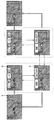
第1モードについて図4を用いて説明する。上記のように、多機能スイッチ34が操作されたときに、ディスプレイ2が起動されていて、かつ、シフト位置がパーキングポジションである場合、ECU5は、第1モードへ移行する。そして、図4の白抜き矢印で示すように、通常モードからカメラ1、ディスプレイ2の調整モードに移行し、調整項目に応じた文字等がディスプレイ2に表示される。
なお、図4、および、後述する図5~図7では、車両が左側通行するような交通規制を有する地域で走行する車両に電子ミラーシステムを搭載した場合の、各モードにおけるディスプレイ2Rの表示内容を図示している。図4~図7では、設定項目名が文字で表示されているが、設定項目がアイコンで表示されていてもよい。
図4に示すように、第1モードでは、上下キー311を下方向に操作することで、実線矢印で示すように調整モードが切り替えられる。すなわち、輝度情報、コントラスト情報、ディスプレイ2R、2Lの表示領域情報、防眩情報、カメラ格納情報、ディスプレイ2R、2Lの後退時広視野角表示情報、ディスプレイ2R、2Lの交差点広視野角表示情報の順に調整モードが切り替えられる。また、上下キー311を上方向に操作することで、破線矢印で示すように、この逆の順に調整モードが切り替えられる。
なお、ディスプレイ2Rの表示領域の調整モードでは、LRスイッチ32をL方向に操作することでもディスプレイ2Lの表示領域の調整モードに切り替えられる。また、ディスプレイ2Lの表示領域の調整モードでは、LRスイッチ32をR方向に操作することでもディスプレイ2Rの表示領域の調整モードに切り替えられる。
また、ディスプレイ2には、各調整モードに応じたメニューが表示される。そして、いずれかの調整モードで多機能スイッチ34が操作されるか、スイッチ部3が操作されずに一定時間が経過すると、白抜き斜線矢印で示すように、調整モードが終了し、ディスプレイ2の表示内容は調整用のメニューが消去された通常のものとなる。
各調整モードでは、左右キー312の操作によって設定情報が変更される。すなわち、輝度情報の調整モードでは、左右キー312の操作によってディスプレイ2に表示される画像の輝度レベルが変更される。例えば、左右キー312を右方向に操作することで輝度レベルが1段階ずつ高くなり、左右キー312を左方向に操作することで輝度レベルが1段階ずつ低くなる。また、コントラスト情報の調整モードでは、輝度情報と同様に、ディスプレイ2に表示される画像のコントラストのレベルが変更される。
また、ディスプレイ2Rの表示領域情報の調整モードでは、左右キー312の操作によってディスプレイ2Rに表示される画像領域が調整される。例えば、左右キー312を右方向に操作することで、ディスプレイ2Rに表示される画像領域が右方向に移動し、左右キー312を左方向に操作することで、ディスプレイ2Rに表示される画像領域が左方向に移動する。同様に、ディスプレイ2Lの表示領域情報の調整モードでは、左右キー312の操作によってディスプレイ2Lに表示される画像領域が調整される。
また、防眩情報の調整モードでは、左右キー312の操作によって、カメラ1の設定やディスプレイ2の表示形式等が、通常のモードと眩しさを軽減する防眩モードとで切り替えられる。また、カメラ格納情報の調整モードでは、左右キー312の操作によって、イグニッションOFF時に自動でカメラ1を格納するか否かの設定が切り替えられる。
また、ディスプレイ2Rの後退時広視野角表示情報、交差点広視野角表示情報の調整モードでは、左右キー312の操作によってディスプレイ2Rの広視野角表示のONとOFFとが切り替えられる。例えば、左右キー312を右方向に操作することで、ディスプレイ2Rの広視野角表示がONになり、左右キー312を左方向に操作することで、ディスプレイ2Rの広視野角表示がOFFになる。同様に、ディスプレイ2Lの後退時広視野角表示情報、交差点広視野角表示情報の調整モードでは、左右キー312の操作によってディスプレイ2Lの広視野角表示のONとOFFとが切り替えられる。
このように、ECU5は、車両の停車中に多機能スイッチ34が操作されると、カメラ1、ディスプレイ2に関する設定情報を変更する調整モードへ移行する。そして、調整モードにおいて調整スイッチ31が操作されると、調整スイッチ31からの信号に応じてシステムの設定情報を変更する。本実施形態では、カメラ1およびディスプレイ2に関する複数の設定情報に対応して複数の調整モードが用意されており、各調整モードにおいて左右キー312が操作されると、ECU5は、左右キー312からの信号に応じてシステムの設定情報を変更する。そして、上下キー311が操作されると、ECU5は、現在の調整モードから別の調整モードへ移行する。
第2モードについて図5を用いて説明する。上記のように、ディスプレイ2が起動されており、シフト位置がパーキングポジションではなく、ヘッドライトがONになっており、かつ、ディスプレイ2の広視野角表示がONになっているとき、ECU5は、第2モードへ移行する。
ヘッドライトがONになるのは、例えば夜間等で車両の周囲が暗い場合である。また、ディスプレイ2の広視野角表示がONになるのは、後退時広視野角表示がONでかつシフト位置がリバースポジションであるときや、交差点広視野角表示がONでかつ交差点に入るとき等である。
図5に示すように、第2モードでは、上下キー311を下方向に操作することで、実線矢印で示すように、防眩情報の調整モードに移行し、上下キー311を上方向に操作することで、破線矢印で示すように、広視野角表示の調整モードに移行する。
なお、図5では、ハッチングの有無で明るい部分と暗い部分とを区別している。ハッチングが付されていない部分は、ハッチングが付された部分よりも明るい部分である。
第1モードと同様に、ディスプレイ2には、各モードに応じたメニューが表示される。そして、いずれかの調整モードで多機能スイッチ34が操作されるか、スイッチ部3が操作されずに一定時間が経過すると、白抜き斜線矢印で示すように、調整モードが終了し、ディスプレイ2の表示内容は調整用のメニューが消去された通常のものとなる。
防眩情報の調整モードでは、左右キー312を右方向に操作することで、一点鎖線矢印で示すように、防眩モードがOFFになる。また、左右キー312を左方向に操作することで、二点鎖線矢印で示すように、防眩モードがONになる。
なお、防眩モードがONになっているときは、図5に示すように、防眩モードがONになっていることを示すアイコン6がディスプレイ2に表示される。
広視野角表示の調整モードでは、左右キー312を右方向に操作することで、広視野角表示が解除される。
第3モードについて図6を用いて説明する。上記のように、ディスプレイ2が起動されており、シフト位置がパーキングポジションではなく、ヘッドライトがONになっていないかまたはディスプレイ2の広視野角表示がONになっていないとき、ECU5は第3モードへ移行する。例えば昼間等で車両の周囲が明るい場合に、第3モードへの移行が行われる。
図6に示すように、第3モードでは、上下キー311を下方向に操作することで、実線矢印で示すように、防眩情報、輝度情報、コントラスト情報の順に調整モードが切り替えられる。また、上下キー311を上方向に操作することで、破線矢印で示すように、この逆の順に調整モードが切り替えられる。
また、第1モードと同様に、ディスプレイ2には、各調整モードに応じたメニューが表示される。各調整モードにおいてスイッチ部3を操作したときの動作は、第1モードと同様である。そして、いずれかの調整モードで多機能スイッチ34が操作されるか、スイッチ部3が操作されずに一定時間が経過すると、白抜き斜線矢印で示すように、調整モードが終了し、ディスプレイ2の表示内容は調整用のメニューが消去された通常のものとなる。
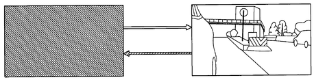
第4モードについて図7を用いて説明する。上記のように、ディスプレイ2が起動されていないとき、ECU5は、第4モードへ移行する。図7の白抜き矢印で示すように、第4モードでは、多機能スイッチ34の操作によってディスプレイ2の表示がONされる。そして、イグニッションがOFFのまま多機能スイッチ34が操作されることなく一定時間が経過すると、白抜き斜線矢印で示すように、ディスプレイ2がOFFされる。
このように、多機能スイッチ34を操作したときに行われる処理が車両状態に応じて変化する。そして、システムの設定情報を変更する調整スイッチ31としては、光学式サイドミラーを備える車両における鏡面角度調整用のスイッチが用いられる。したがって、設定された複数の処理ごとにスイッチを新設する必要がなく、スイッチの数の増加を抑制することができる。
(他の実施形態)
なお、本開示は上記した実施形態に限定されるものではなく、適宜変更が可能である。また、上記実施形態において、実施形態を構成する要素は、特に必須であると明示した場合および原理的に明らかに必須であると考えられる場合等を除き、必ずしも必須のものではないことは言うまでもない。
なお、本開示は上記した実施形態に限定されるものではなく、適宜変更が可能である。また、上記実施形態において、実施形態を構成する要素は、特に必須であると明示した場合および原理的に明らかに必須であると考えられる場合等を除き、必ずしも必須のものではないことは言うまでもない。
例えば、上下キー311を第2調整キーとして用い、左右キー312を第1調整キーとして用いてもよい。
また、上記第1実施形態では、調整モードを上下キー311で切り替えたが、調整モードを多機能スイッチ34で切り替えるようにしてもよい。そして、車両の停車中に多機能スイッチ34が操作されると、複数の調整モードと通常のモードとを順に切り替え、各調整モードにおいて上下キー311が操作されると、各調整モードに対応した設定情報を変更するようにしてもよい。
また、上記のように多機能スイッチ34の操作によって複数の調整モードと通常のモードとが順に切り替えられる場合には、2つの設定情報を同時に調整するようにしてもよい。例えば、ディスプレイ2に輝度調整用のメニューとコントラスト調整用のメニューを同時に表示し、上下キー311の操作によって輝度が変更され、左右キー312の操作によってコントラストが変更されるようにしてもよい。
また、上記第1実施形態では、カメラ1およびディスプレイ2に関して、カメラ格納情報、表示領域情報、輝度情報、コントラスト情報、防眩情報、後退時広視野角表示情報、交差点広視野角表示情報が設定されているが、他の情報が追加して設定されていてもよい。例えば、電子ミラーシステムが車両の後退時や右左折時にディスプレイ2の表示形式や表示領域が自動で変更される機能を備え、このような機能のON、OFFに関する情報が設定されていてもよい。また、第1、第3モードにおいて、各調整モードの切り替えの順序を変えてもよい。
また、光学式サイドミラーを備える車両のスイッチ部に電子ミラーシステムで使用されないスイッチがある場合には、そのスイッチを多機能スイッチ34として用いてもよい。例えば、カメラ1を格納する機能を電子ミラーシステムが備えない場合には、カメラ格納スイッチ33を多機能スイッチとして用いてもよい。このように、ミラーが電子化されることで不要となるスイッチを多機能スイッチとすることにより、スイッチの数の増加をさらに抑制できる。
また、車速に応じて調整モードの数を増減させてもよい。例えば、低速時には高速時に比べて調整モードの数を多くしてもよい。
また、多機能スイッチ34を例えば上面に液晶パネルを備える構成として、この液晶パネルに車両状態に応じた文字やアイコンを表示させてもよい。例えば、多機能スイッチ34が備える液晶パネルに、走行中には防眩モードへの移行を示す「防眩」の文字を表示させ、停車中には調整モードへの移行を示す「調整」の文字を表示させてもよい。また、多機能スイッチ34をLED等の光源を備える構成として、車両状態に応じて多機能スイッチ34が発する光の色を変化させてもよい。
また、車両が備えるディスプレイ2以外のディスプレイに設定情報等を表示してもよい。
また、カメラ1が起動されていないときに多機能スイッチ34を操作することでカメラ1が起動されるようにしてもよい。
また、走行時に多機能スイッチ34を操作することで防眩モードのON、OFFを切り替えるようにしてもよい。
また、多機能スイッチ34を所定時間継続して押下することで、システムの特定の設定情報を変更するようにしてもよい。例えば、防眩モードの設定用のメニューが表示されていないときにも、多機能スイッチ34を所定時間継続して押下することで、防眩モードのON、OFFが切り替えられるようにしてもよい。
また、多機能スイッチ34を所定時間継続して押下することで、ECU5が、設定された複数の処理の中から車両の状態に応じて選択される処理を実行するようにしてもよい。また、多機能スイッチ34を押下してから所定時間が経過する前に押下を解除することで、システムの特定の設定情報を変更するようにしてもよい。
また、上記第1実施形態では、車両が左側通行するような交通規制を有する地域で走行する車両に電子ミラーシステムを搭載する例を示したが、車両が右側通行するような交通規制を有する地域で走行する車両に電子ミラーシステムを搭載してもよい。
Claims (9)
- 車両に搭載される電子ミラーシステムであって、
前記車両の周囲を撮影するカメラ(1、1L、1R)と、
前記カメラの撮影画像を表示する表示部(2、2L、2R)と、
調整スイッチ(31)および多機能スイッチ(33、34)を備えるスイッチ部(3)と、
前記スイッチ部からの信号に応じた処理を行う制御部(5)と、を備え、
前記制御部は、前記多機能スイッチが操作されると、設定された複数の処理の中から車両の状態に応じて選択される処理を実行し、実行した処理がシステムの設定情報を変更するモードへの移行である場合に、該移行の後に前記調整スイッチが操作されると、前記調整スイッチからの信号に応じて該設定情報を変更する電子ミラーシステム。 - 前記制御部は、車両の停車中に前記多機能スイッチが操作されると、システムの設定情報を変更する調整モードへの移行を行い、該調整モードにおいて前記調整スイッチが操作されると、前記調整スイッチからの信号に応じて設定情報を変更する請求項1に記載の電子ミラーシステム。
- 前記制御部には、前記表示部または前記カメラに関する設定情報が複数記憶されており、
前記調整モードは、複数の設定情報に対応して複数用意されており、
前記調整スイッチは、複数の前記調整モードから1つを選択するための第1調整キー(311、312)、および、前記第1調整キーとは別の第2調整キー(311、312)を備えており、
前記制御部は、複数の前記調整モードのうち1つの調整モードにおいて前記第1調整キーが操作されると、該調整モードから別の調整モードへ移行し、前記第2調整キーが操作されると、前記第2調整キーからの信号に応じて前記表示部または前記カメラに関する設定情報を変更する請求項2に記載の電子ミラーシステム。 - 前記制御部は、前記調整モードにおいて前記多機能スイッチが操作されると、前記調整モードを終了して通常のモードへ移行する請求項3に記載の電子ミラーシステム。
- 前記制御部には、前記表示部または前記カメラに関する設定情報が複数記憶されており、
前記調整モードは、複数の設定情報に対応して複数用意されており、
前記制御部は、車両の停車中に前記多機能スイッチが操作されると、複数の前記調整モードと通常のモードとを順に切り替え、複数の前記調整モードのうち1つの調整モードにおいて前記調整スイッチが操作されると、前記調整スイッチからの信号に応じて前記表示部または前記カメラに関する設定情報を変更する請求項2に記載の電子ミラーシステム。 - 前記制御部は、車両の走行中に前記多機能スイッチが操作されると、前記表示部の表示モードを変更する請求項1ないし5のいずれか1つに記載の電子ミラーシステム。
- 前記制御部は、前記カメラまたは前記表示部が起動されていないときに前記多機能スイッチが操作されると、前記カメラまたは前記表示部を起動する請求項1ないし6のいずれか1つに記載の電子ミラーシステム。
- 前記制御部は、前記多機能スイッチが所定時間継続して押下されると、システムの特定の設定情報を変更する請求項1ないし7のいずれか1つに記載の電子ミラーシステム。
- 前記制御部は、前記多機能スイッチが所定時間継続して押下されると、設定された複数の処理の中から車両の状態に応じて選択される処理を実行し、前記多機能スイッチが押下されてから所定時間が経過する前に押下が解除されると、システムの特定の設定情報を変更する請求項1ないし7のいずれか1つに記載の電子ミラーシステム。
Priority Applications (3)
| Application Number | Priority Date | Filing Date | Title |
|---|---|---|---|
| DE112018005292.3T DE112018005292B4 (de) | 2017-09-19 | 2018-09-13 | Elektronisches Spiegelsystem |
| CN201880060952.9A CN111148654B (zh) | 2017-09-19 | 2018-09-13 | 电子镜系统 |
| US16/821,086 US11485287B2 (en) | 2017-09-19 | 2020-03-17 | Electronic mirror system |
Applications Claiming Priority (2)
| Application Number | Priority Date | Filing Date | Title |
|---|---|---|---|
| JP2017179480A JP6848779B2 (ja) | 2017-09-19 | 2017-09-19 | 電子ミラーシステム |
| JP2017-179480 | 2017-09-19 |
Related Child Applications (1)
| Application Number | Title | Priority Date | Filing Date |
|---|---|---|---|
| US16/821,086 Continuation US11485287B2 (en) | 2017-09-19 | 2020-03-17 | Electronic mirror system |
Publications (1)
| Publication Number | Publication Date |
|---|---|
| WO2019059103A1 true WO2019059103A1 (ja) | 2019-03-28 |
Family
ID=65809751
Family Applications (1)
| Application Number | Title | Priority Date | Filing Date |
|---|---|---|---|
| PCT/JP2018/034055 Ceased WO2019059103A1 (ja) | 2017-09-19 | 2018-09-13 | 電子ミラーシステム |
Country Status (5)
| Country | Link |
|---|---|
| US (1) | US11485287B2 (ja) |
| JP (1) | JP6848779B2 (ja) |
| CN (1) | CN111148654B (ja) |
| DE (1) | DE112018005292B4 (ja) |
| WO (1) | WO2019059103A1 (ja) |
Families Citing this family (1)
| Publication number | Priority date | Publication date | Assignee | Title |
|---|---|---|---|---|
| EP3822124A1 (en) * | 2019-11-14 | 2021-05-19 | Ningbo Geely Automobile Research & Development Co. Ltd. | A control system, method and a computer program product at a vehicle for controlling the views of the surroundings of the vehicle by a vehicle occupant |
Citations (7)
| Publication number | Priority date | Publication date | Assignee | Title |
|---|---|---|---|---|
| JPH068111U (ja) * | 1992-07-06 | 1994-02-01 | マツダ株式会社 | 車両用操作制御装置 |
| JP2006096249A (ja) * | 2004-09-30 | 2006-04-13 | Mazda Motor Corp | 車両用情報表示装置 |
| JP2008030674A (ja) * | 2006-07-31 | 2008-02-14 | Mazda Motor Corp | 車両用情報処理装置 |
| JP2008068673A (ja) * | 2006-09-12 | 2008-03-27 | Toyota Motor Corp | 車両用入力装置 |
| JP2010064520A (ja) * | 2008-09-08 | 2010-03-25 | Alpine Electronics Inc | 動作パラメータ設定装置および動作パラメータ設定方法 |
| US20140085471A1 (en) * | 2012-09-25 | 2014-03-27 | Lg Innotek Co., Ltd. | Display room mirror system |
| JP2016185720A (ja) * | 2015-03-27 | 2016-10-27 | 株式会社ホンダアクセス | 車両用入力システム |
Family Cites Families (17)
| Publication number | Priority date | Publication date | Assignee | Title |
|---|---|---|---|---|
| JPS5899152U (ja) | 1981-12-26 | 1983-07-06 | 富士重工業株式会社 | 自動車のスイツチ構造 |
| JPS6171250A (ja) | 1984-09-14 | 1986-04-12 | Omron Tateisi Electronics Co | 車両のスイツチ制御装置 |
| JPS6428047A (en) | 1987-07-21 | 1989-01-30 | Fuji Heavy Ind Ltd | Vehicle mounted touch switch device |
| JP2000159018A (ja) | 1998-11-26 | 2000-06-13 | Yazaki Corp | 車両用スイッチ装置 |
| JP4266762B2 (ja) * | 2003-09-25 | 2009-05-20 | カルソニックカンセイ株式会社 | 操作者判別装置及びマルチファンクションスイッチ |
| JP4930728B2 (ja) * | 2008-03-31 | 2012-05-16 | 株式会社エクォス・リサーチ | 表示装置 |
| JP2012096670A (ja) | 2010-11-02 | 2012-05-24 | Panasonic Corp | 入力装置及び入力方法 |
| US9264672B2 (en) * | 2010-12-22 | 2016-02-16 | Magna Mirrors Of America, Inc. | Vision display system for vehicle |
| JP5858650B2 (ja) * | 2011-06-08 | 2016-02-10 | 富士通テン株式会社 | 画像生成装置、画像表示システム、及び、画像生成方法 |
| US8626407B2 (en) * | 2011-07-26 | 2014-01-07 | Kubota Corporation | Work vehicle |
| WO2013067082A1 (en) * | 2011-11-01 | 2013-05-10 | Magna Mirrors Of America, Inc. | Vision system with door mounted exterior mirror and display |
| DE102011118253B4 (de) | 2011-11-11 | 2013-09-12 | Audi Ag | Verfahren zum Betrieb eines elektronischen Rückspiegels eines Kraftfahrzeugs und Kraftfahrzeug |
| JP5565421B2 (ja) | 2012-02-07 | 2014-08-06 | 株式会社デンソー | 車載操作装置 |
| DE102012004639A1 (de) | 2012-03-07 | 2013-09-12 | Audi Ag | Kraftfahrzeug mit einem elektronischen Rückspiegel |
| JP2016092782A (ja) * | 2014-11-11 | 2016-05-23 | トヨタ自動車株式会社 | 車両用視界支援装置 |
| JP2016141246A (ja) * | 2015-02-02 | 2016-08-08 | 株式会社東海理化電機製作所 | ミラー制御装置及びミラー制御システム |
| JP6261640B2 (ja) | 2016-03-30 | 2018-01-17 | 新日鐵住金ステンレス株式会社 | 加工性に優れた排気部品用フェライト系ステンレス鋼板、鋼管およびその製造方法 |
-
2017
- 2017-09-19 JP JP2017179480A patent/JP6848779B2/ja active Active
-
2018
- 2018-09-13 WO PCT/JP2018/034055 patent/WO2019059103A1/ja not_active Ceased
- 2018-09-13 DE DE112018005292.3T patent/DE112018005292B4/de active Active
- 2018-09-13 CN CN201880060952.9A patent/CN111148654B/zh active Active
-
2020
- 2020-03-17 US US16/821,086 patent/US11485287B2/en active Active
Patent Citations (7)
| Publication number | Priority date | Publication date | Assignee | Title |
|---|---|---|---|---|
| JPH068111U (ja) * | 1992-07-06 | 1994-02-01 | マツダ株式会社 | 車両用操作制御装置 |
| JP2006096249A (ja) * | 2004-09-30 | 2006-04-13 | Mazda Motor Corp | 車両用情報表示装置 |
| JP2008030674A (ja) * | 2006-07-31 | 2008-02-14 | Mazda Motor Corp | 車両用情報処理装置 |
| JP2008068673A (ja) * | 2006-09-12 | 2008-03-27 | Toyota Motor Corp | 車両用入力装置 |
| JP2010064520A (ja) * | 2008-09-08 | 2010-03-25 | Alpine Electronics Inc | 動作パラメータ設定装置および動作パラメータ設定方法 |
| US20140085471A1 (en) * | 2012-09-25 | 2014-03-27 | Lg Innotek Co., Ltd. | Display room mirror system |
| JP2016185720A (ja) * | 2015-03-27 | 2016-10-27 | 株式会社ホンダアクセス | 車両用入力システム |
Also Published As
| Publication number | Publication date |
|---|---|
| DE112018005292T5 (de) | 2020-06-18 |
| DE112018005292B4 (de) | 2022-03-17 |
| US20200215978A1 (en) | 2020-07-09 |
| CN111148654A (zh) | 2020-05-12 |
| JP2019055614A (ja) | 2019-04-11 |
| US11485287B2 (en) | 2022-11-01 |
| JP6848779B2 (ja) | 2021-03-24 |
| CN111148654B (zh) | 2023-05-19 |
Similar Documents
| Publication | Publication Date | Title |
|---|---|---|
| US11052823B2 (en) | Vehicle rear monitoring system | |
| US8319617B2 (en) | Vehicle surroundings monitoring apparatus | |
| JP6481273B2 (ja) | 車両用表示装置 | |
| CN107298050B (zh) | 图像显示装置 | |
| JP5466571B2 (ja) | 車両用表示装置 | |
| JPH02302795A (ja) | 車載モニター装置のモニター画面自動調整装置 | |
| US20100020176A1 (en) | Image processing system, imaging device, image processing method, and computer program | |
| US10647260B2 (en) | Vehicle surroundings display device | |
| JP2008162481A (ja) | 視界支援装置 | |
| US11485287B2 (en) | Electronic mirror system | |
| JP7051667B2 (ja) | 車載装置 | |
| CN111391754A (zh) | 电子镜系统 | |
| JP5488250B2 (ja) | 車両用表示装置 | |
| US20200207271A1 (en) | Electronic mirror system | |
| WO2024241438A1 (ja) | 表示装置の制御方法及び表示制御装置 | |
| JP2018074440A (ja) | 車両後方画像表示装置 | |
| JP2024130172A (ja) | 表示制御方法及び表示制御装置 | |
| JP2006044472A (ja) | 車両用周囲確認装置 | |
| JP6815687B2 (ja) | 車両用表示システム | |
| JP2025121689A (ja) | 電子インナーミラー装置 | |
| JP2024025908A (ja) | 車両用表示装置 | |
| JP2025122899A (ja) | 画像生成装置、画像生成方法、及び画像生成プログラム | |
| JP2010069915A (ja) | 車両周囲監視装置 | |
| JP2019028371A (ja) | 表示制御装置 |
Legal Events
| Date | Code | Title | Description |
|---|---|---|---|
| 121 | Ep: the epo has been informed by wipo that ep was designated in this application |
Ref document number: 18858397 Country of ref document: EP Kind code of ref document: A1 |
|
| 122 | Ep: pct application non-entry in european phase |
Ref document number: 18858397 Country of ref document: EP Kind code of ref document: A1 |