WO2019058705A1 - エンジンシステム - Google Patents
エンジンシステム Download PDFInfo
- Publication number
- WO2019058705A1 WO2019058705A1 PCT/JP2018/025136 JP2018025136W WO2019058705A1 WO 2019058705 A1 WO2019058705 A1 WO 2019058705A1 JP 2018025136 W JP2018025136 W JP 2018025136W WO 2019058705 A1 WO2019058705 A1 WO 2019058705A1
- Authority
- WO
- WIPO (PCT)
- Prior art keywords
- purge
- engine
- fuel
- intake
- ecu
- Prior art date
Links
Images


Classifications
-
- F—MECHANICAL ENGINEERING; LIGHTING; HEATING; WEAPONS; BLASTING
- F02—COMBUSTION ENGINES; HOT-GAS OR COMBUSTION-PRODUCT ENGINE PLANTS
- F02D—CONTROLLING COMBUSTION ENGINES
- F02D41/00—Electrical control of supply of combustible mixture or its constituents
- F02D41/02—Circuit arrangements for generating control signals
- F02D41/04—Introducing corrections for particular operating conditions
- F02D41/12—Introducing corrections for particular operating conditions for deceleration
-
- F—MECHANICAL ENGINEERING; LIGHTING; HEATING; WEAPONS; BLASTING
- F02—COMBUSTION ENGINES; HOT-GAS OR COMBUSTION-PRODUCT ENGINE PLANTS
- F02B—INTERNAL-COMBUSTION PISTON ENGINES; COMBUSTION ENGINES IN GENERAL
- F02B37/00—Engines characterised by provision of pumps driven at least for part of the time by exhaust
-
- F—MECHANICAL ENGINEERING; LIGHTING; HEATING; WEAPONS; BLASTING
- F02—COMBUSTION ENGINES; HOT-GAS OR COMBUSTION-PRODUCT ENGINE PLANTS
- F02D—CONTROLLING COMBUSTION ENGINES
- F02D41/00—Electrical control of supply of combustible mixture or its constituents
- F02D41/0025—Controlling engines characterised by use of non-liquid fuels, pluralities of fuels, or non-fuel substances added to the combustible mixtures
- F02D41/003—Adding fuel vapours, e.g. drawn from engine fuel reservoir
- F02D41/0032—Controlling the purging of the canister as a function of the engine operating conditions
-
- F—MECHANICAL ENGINEERING; LIGHTING; HEATING; WEAPONS; BLASTING
- F02—COMBUSTION ENGINES; HOT-GAS OR COMBUSTION-PRODUCT ENGINE PLANTS
- F02D—CONTROLLING COMBUSTION ENGINES
- F02D41/00—Electrical control of supply of combustible mixture or its constituents
- F02D41/02—Circuit arrangements for generating control signals
- F02D41/04—Introducing corrections for particular operating conditions
- F02D41/12—Introducing corrections for particular operating conditions for deceleration
- F02D41/123—Introducing corrections for particular operating conditions for deceleration the fuel injection being cut-off
- F02D41/126—Introducing corrections for particular operating conditions for deceleration the fuel injection being cut-off transitional corrections at the end of the cut-off period
-
- F—MECHANICAL ENGINEERING; LIGHTING; HEATING; WEAPONS; BLASTING
- F02—COMBUSTION ENGINES; HOT-GAS OR COMBUSTION-PRODUCT ENGINE PLANTS
- F02D—CONTROLLING COMBUSTION ENGINES
- F02D43/00—Conjoint electrical control of two or more functions, e.g. ignition, fuel-air mixture, recirculation, supercharging or exhaust-gas treatment
-
- F—MECHANICAL ENGINEERING; LIGHTING; HEATING; WEAPONS; BLASTING
- F02—COMBUSTION ENGINES; HOT-GAS OR COMBUSTION-PRODUCT ENGINE PLANTS
- F02M—SUPPLYING COMBUSTION ENGINES IN GENERAL WITH COMBUSTIBLE MIXTURES OR CONSTITUENTS THEREOF
- F02M25/00—Engine-pertinent apparatus for adding non-fuel substances or small quantities of secondary fuel to combustion-air, main fuel or fuel-air mixture
- F02M25/08—Engine-pertinent apparatus for adding non-fuel substances or small quantities of secondary fuel to combustion-air, main fuel or fuel-air mixture adding fuel vapours drawn from engine fuel reservoir
-
- F—MECHANICAL ENGINEERING; LIGHTING; HEATING; WEAPONS; BLASTING
- F02—COMBUSTION ENGINES; HOT-GAS OR COMBUSTION-PRODUCT ENGINE PLANTS
- F02D—CONTROLLING COMBUSTION ENGINES
- F02D23/00—Controlling engines characterised by their being supercharged
- F02D23/02—Controlling engines characterised by their being supercharged the engines being of fuel-injection type
-
- F—MECHANICAL ENGINEERING; LIGHTING; HEATING; WEAPONS; BLASTING
- F02—COMBUSTION ENGINES; HOT-GAS OR COMBUSTION-PRODUCT ENGINE PLANTS
- F02D—CONTROLLING COMBUSTION ENGINES
- F02D41/00—Electrical control of supply of combustible mixture or its constituents
- F02D41/0002—Controlling intake air
- F02D41/0007—Controlling intake air for control of turbo-charged or super-charged engines
-
- Y—GENERAL TAGGING OF NEW TECHNOLOGICAL DEVELOPMENTS; GENERAL TAGGING OF CROSS-SECTIONAL TECHNOLOGIES SPANNING OVER SEVERAL SECTIONS OF THE IPC; TECHNICAL SUBJECTS COVERED BY FORMER USPC CROSS-REFERENCE ART COLLECTIONS [XRACs] AND DIGESTS
- Y02—TECHNOLOGIES OR APPLICATIONS FOR MITIGATION OR ADAPTATION AGAINST CLIMATE CHANGE
- Y02T—CLIMATE CHANGE MITIGATION TECHNOLOGIES RELATED TO TRANSPORTATION
- Y02T10/00—Road transport of goods or passengers
- Y02T10/10—Internal combustion engine [ICE] based vehicles
- Y02T10/12—Improving ICE efficiencies
Definitions
- the technology disclosed in this specification includes an engine equipped with a supercharger, an intake amount adjustment valve that adjusts an intake amount of the engine, and an evaporative fuel processing device that processes evaporative fuel generated in a fuel tank,
- the present invention relates to an engine system configured to control an intake amount adjustment valve and an evaporative fuel processing device at the time of engine deceleration.
- This technology includes an engine equipped with a supercharger, an electronic throttle device for adjusting the intake amount of the engine, and a new air introduction device for introducing new air downstream from the electronic throttle device (a new air introduction passage and a new air introduction valve And an EGR device (including an EGR passage and an EGR valve) for recirculating a portion of the exhaust gas discharged from the engine to the engine as EGR gas, and a leak EGR bypass passage branched from the fresh air introduction passage.
- an engine equipped with a supercharger
- an electronic throttle device for adjusting the intake amount of the engine
- a new air introduction device for introducing new air downstream from the electronic throttle device (a new air introduction passage and a new air introduction valve
- an EGR device including an EGR passage and an EGR valve) for recirculating a portion of the exhaust gas discharged from the engine to the engine as EGR gas, and a leak EGR bypass passage branched from the fresh air introduction passage.
- an evaporated fuel processing device including a canister, a purge passage, and a purge valve
- evaporated fuel processing device including a canister, a purge passage, and a purge valve
- the outlet of the purge passage for leading the vapor flowing out of the canister to the intake passage is often provided in the intake passage upstream of the supercharger (compressor).
- the path of the intake passage from the outlet of the purge passage to the engine tends to be long and the volume also tends to be large.
- the fuel supply to the engine may be cut off (fuel cut), but normally, at the same time as the fuel cut, the purge of the vapor from the purge passage to the intake passage is shut off (purge cut ) To be done. This may cause the vapor (including unburned fuel) to flow through the engine to the catalyst in the exhaust passage, and the temperature of the catalyst may increase excessively if the fuel purge continues when the fuel cut is performed. Yes, to avoid this situation.
- the evaporative fuel processing device when the electronic throttle device is closed to a predetermined deceleration opening when the engine is decelerating, the vapor is placed in the intake passage upstream from the electronic throttle device. A large amount of intake air may be left, and the residual intake air may flow to the engine through the small opening of the electronic throttle device and may flow into the catalyst. Therefore, even if the fuel cut at the time of deceleration and the purge cut simultaneously, residual intake air containing vapor continues to flow into the catalyst, the temperature of the catalyst excessively rises, and the catalyst may be deteriorated or melted away due to overheating.
- This disclosed technology has been made in view of the above circumstances, and the purpose thereof is to use an intake amount control valve provided in an intake passage downstream of a turbocharger and an evaporative fuel generated in a fuel tank from the turbocharger. And evaporative fuel processing device for purging into the intake air passage upstream, and when fuel cut is performed when the engine is decelerating, the inflow of evaporative fuel from the engine to the catalyst is suppressed to prevent an excessive rise in the temperature of the catalyst. To provide an engine system that made it possible.
- one aspect of the disclosed technology includes an engine, an intake passage for introducing intake air into the engine, an exhaust passage for extracting exhaust gas from the engine, and fuel. And an injector for injecting fuel stored in the fuel tank, the fuel supply device for supplying fuel to the engine, and an intake passage disposed to adjust the amount of intake air flowing through the intake passage Amount adjustment valve, a compressor disposed in the intake passage, a turbine disposed in the exhaust passage, and a rotary shaft that integrally connects the compressor and the turbine so as to integrally boost the intake air in the intake passage , A canister for temporarily collecting evaporated fuel generated in the fuel tank, and purging the evaporated fuel collected in the canister to the intake passage
- the purge passage, the purge passage having an outlet connected to the intake passage upstream of the compressor, and a purge adjusting means for adjusting the amount of evaporated fuel purged from the purge passage to the intake passage; At least an injector, an intake amount control valve, and a purge adjusting means according to an operating state
- the control means for controlling the engine when the control means determines that the engine starts to decelerate based on the detected operating state of the engine during operation of the engine, evaporation from the purge passage to the intake passage
- the purge control means are controlled to shut off the fuel purge and then the engine is shut off to shut off the fuel supply. And intent to control the Kuta.
- the intake amount adjustment valve is opened.
- the valve is closed from the valve state to the deceleration opening degree, and from the deceleration start, the intake air including the evaporated fuel remains in the intake passage upstream of the intake amount adjustment valve.
- This residual intake air flows to the engine through the slight opening of the intake control valve and flows to the catalyst in the exhaust passage.
- the purge of the evaporated fuel is first shut off (purge cut), and then the fuel supply is shut off (fuel cut).
- the purge cut is performed before the fuel cut is performed, and by the time of the fuel cut, the residual intake including the evaporated fuel upstream from the intake amount adjustment valve flows to the engine, scavenged, and burned in the engine. This eliminates the evaporative fuel flowing to the catalyst after the fuel cut is performed.
- control means determines that the engine is in the predetermined operation state after controlling the purge adjustment means to shut off the purge of the evaporated fuel. Control the injector to shut off the fuel supply.
- the fuel cut is performed when the engine is in a predetermined operation state.
- the control means controls the purge adjustment means to shut off the purge of the evaporated fuel, and then enters the detected operating state. Based on this, the amount of residual intake including evaporated fuel remaining in the intake passage upstream of the intake amount adjustment valve is determined, and it is determined that scavenging of the residual intake of that amount is completed, and then the fuel supply is shut off. It is intended to control the injector.
- the evaporative fuel remaining in the intake passage upstream from the intake amount adjustment valve after the purge cut of the evaporative fuel is performed
- the amount of residual intake, including B. is determined, and a fuel cut is performed after scavenging of that amount of residual intake is complete. Therefore, the purge cut is performed, and the fuel cut is performed after the residual intake including the evaporated fuel is reliably eliminated from the intake passage upstream of the intake amount adjustment valve.
- the overheating of the catalyst becomes a problem mainly when the temperature of the catalyst becomes higher than a predetermined reference temperature .
- the purge cut is performed in accordance with the catalyst temperature state.
- the operating state detection means includes an air fuel ratio detection means for detecting an air fuel ratio of the engine, and the control means detects The delay time for delaying the shutoff of the evaporated fuel purge is determined based on the change in the air-fuel ratio, and when it is determined that the engine starts to decelerate during the operation of the engine, to shut off the evaporated fuel purge after the delay time has elapsed. Control of the purge adjustment means.
- control means purges the fuel vapor purge rate so as to gradually decrease when the fuel vapor purge is shut off. It is intended to control the adjustment means.
- the purge rate is adjusted to be gradually reduced Therefore, the evaporative fuel flowing to the engine never disappears at a stretch.
- the purge rate of the evaporated fuel is adjusted to gradually increase when restarting the purge of the evaporated fuel. Flowing evaporative fuel does not increase at a stretch.
- an output operation means operated by a driver to control an output of the engine is further provided, and an operating state detection means
- the output operation means includes an output operation amount detection means for detecting an operation amount of the output operation means, and a valve opening degree detection means for detecting an opening degree of the intake amount control valve, the control means detecting the operation amount It is an object of the present invention to determine the start of deceleration of the engine based on at least one of the change speed of and the change speed of the detected opening.
- the deceleration start of the engine is judged early.
- control means judges the start of deceleration of the engine based on the change speed of the detected operation amount, and the detected opening degree is predetermined. It is intended to control the purge adjusting means to shut off the purge of the evaporative fuel when it is determined that the opening degree is smaller than the small opening degree.
- the deceleration start of the engine is judged based on the change speed of the operation amount of the output operation means, and the opening degree of the intake amount adjustment valve is When it becomes smaller than the predetermined small opening degree, the purge cut of the evaporative fuel is performed. Therefore, the evaporative fuel remaining in the intake passage upstream of the intake amount adjustment valve flows to the engine until the opening amount of the intake amount adjustment valve becomes smaller than the predetermined small opening degree.
- the operating condition detection means includes rotational speed detection means for detecting the rotational speed of the engine, and the control means detects the rotational speed detected The purpose is to set the predetermined small opening larger as the
- the amount of evaporative fuel remaining in the intake passage upstream of the intake amount adjustment valve at the time of engine deceleration decreases the engine rotational speed The higher the
- the predetermined small opening degree to be compared with the opening degree of the intake amount adjustment valve is set larger as the rotational speed of the engine becomes higher.
- the execution time of the purge cut is adjusted.
- the intake amount control valve provided in the intake passage downstream of the turbocharger, and the evaporated fuel processing device for purging the evaporated fuel generated in the fuel tank to the intake passage upstream of the turbocharger In the engine system, the fuel flow from the engine to the catalyst can be suppressed when the fuel cut is performed when the engine decelerates, and an excessive increase in the temperature of the catalyst can be prevented.
- the inflow of evaporated fuel from the engine to the catalyst can be made more surely It is possible to suppress the excessive rise of the temperature of the catalyst with high accuracy.
- the configuration of the above (4) in addition to the effect of the configuration of the above (1) or (2), it is possible to extend the timing of purge cut to a temperature at which the catalyst may actually overheat. In this case, as a result, the purge flow rate of the evaporated fuel can be increased.
- the execution timing of the purge cut can be optimized in accordance with the temperature of the catalyst, so the drop of the purge flow rate is suppressed Coexistence of the temperature rise suppression of the catalyst and the catalyst can be achieved.
- the execution of the purge cut during the engine deceleration causes the air fuel ratio to be over lean or the catalyst to rise in temperature. Can be prevented.
- the purge cut can be executed from an early time after the start of deceleration of the engine. It is possible to suppress a wasteful increase of the evaporated fuel in the intake passage further upstream.
- the purge cut can be performed at an optimal timing at which the scavenging of the evaporated fuel remaining upstream of the intake amount control valve can be completed.
- FIG. 1 is a schematic configuration view showing an engine system according to a first embodiment.
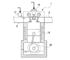
- FIG. 2 is a cross-sectional view showing an outline of an engine according to the first embodiment.
- 4 is a flowchart according to the first embodiment and showing the contents of purge control.
- a fuel cut execution load map according to a first embodiment which is referred to in order to obtain a fuel cut execution load according to an engine rotational speed.
- the time chart which concerns on 1st Embodiment and shows the behavior of the various parameters in purge control.
- the flowchart which concerns on 2nd Embodiment and which shows the content of purge control.
- the time chart which concerns on 2nd Embodiment and shows the behavior of the various parameters in purge control.
- the flowchart which concerns on 3rd Embodiment and which shows the content of purge control The small opening degree map referred in order to obtain
- the flowchart which concerns on 5th Embodiment and shows the content of purge control The time chart which concerns on 5th Embodiment and shows the behavior of the various parameters in purge control.
- require the compressor exit pressure just before deceleration according to 6th Embodiment according to the engine rotational speed and engine load just before deceleration.
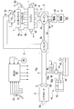
- FIG. 1 is a schematic configuration view of an engine system of this embodiment.
- a gasoline engine system (hereinafter simply referred to as "engine system") mounted on a motor vehicle includes an engine 1 having a plurality of cylinders.
- the engine 1 is a four-cylinder four-cycle reciprocating engine, and includes known configurations such as a piston 19 and a crankshaft 20 (see FIG. 2) described later.
- the engine 1 is provided with an intake passage 2 for introducing intake air to each cylinder, and an exhaust passage 3 for leading exhaust gas from each cylinder.
- a supercharger 5 is provided in the intake passage 2 and the exhaust passage 3.
- an intake port 2a, an air cleaner 4, a compressor 5a of the supercharger 5, an electronic throttle device 6, an intercooler 7, and an intake manifold 8 are provided in this order from the upstream side.
- the electronic throttle device 6 is disposed in the intake passage 2 upstream of the intake manifold 8 and the intercooler 7 and is driven to open and close according to the accelerator operation by the driver to adjust the amount of intake air flowing through the intake passage 2. It has become.
- the electronic throttle device 6 is configured by a motor type motor-operated valve, and detects a throttle valve 6a which is opened and closed by a motor (not shown) and an opening degree (throttle opening degree) TA of the throttle valve 6a. And a throttle sensor 51.
- the throttle sensor 51 corresponds to an example of the valve opening detection means in the disclosed technology.
- the electronic throttle device 6 corresponds to an example of the intake amount adjustment valve in the disclosed technology.
- the intake manifold 8 is disposed immediately upstream of the engine 1 and a plurality of (four) branches for distributing a surge tank 8a into which intake air is introduced and intake air introduced into the surge tank 8a to each cylinder of the engine 1 And a tube 8b.
- an exhaust manifold 9, a turbine 5 b of the turbocharger 5 and two catalysts 10 and 11 arranged in series are provided in this order from the upstream side.
- the two catalysts 10 and 11 are for purifying the exhaust gas, and can be constituted by, for example, a three-way catalyst.
- the supercharger 5 is provided to boost the intake air in the intake passage 2, and as an example, a compressor 5a disposed in the intake passage 2, a turbine 5b disposed in the exhaust passage 3, a compressor 5a and a turbine 5b And a rotation shaft 5c coupled integrally rotatably.
- the turbine 5 b is rotated by the exhaust gas flowing through the exhaust passage 3, and the compressor 5 a is rotationally operated in conjunction with the rotation of the turbine 5 b so that the intake air flowing through the intake passage 2 is pressurized.
- the intercooler 7 is configured to cool the intake air boosted by the compressor 5a.
- the outline of the engine 1 is shown by FIG. 2 by sectional drawing.
- the engine 1 is provided with an injector 17 for injecting fuel corresponding to each cylinder.
- the injector 17 is configured to inject the fuel supplied from the fuel tank 40 (see FIG. 1) for storing the fuel into each cylinder of the engine 1.
- a combustible mixture is formed by the fuel injected from the injector 17 and the intake air introduced from the intake manifold 8.
- the injector 17 and the fuel tank 40 are an example of the components which comprise the fuel supply system in this indication art.
- the engine 1 is provided with an igniter 18 corresponding to each cylinder.
- the igniter 18 is configured to ignite the combustible mixture formed in each cylinder.
- the combustible mixture in each cylinder explodes and burns by the ignition operation of the igniter 18, and the exhaust gas after combustion is exhausted to the outside from each cylinder through the exhaust manifold 9, the turbine 5b and each catalyst 10, 11.
- the piston 19 moves up and down, and the crankshaft 20 rotates, whereby power is obtained for the engine 1.
- the fuel supply system comprises a fuel tank 40 for storing fuel.
- the engine system also includes an evaporative fuel processing device 41 for collecting and processing evaporative fuel (vapor) generated in the fuel tank 40 without being released to the atmosphere.
- the device 41 includes a canister 42, a purge passage 43, a purge pump 44 and a purge valve 45.
- the canister 42 is designed to temporarily collect vapor generated in the fuel tank 40 through the vapor passage 46.
- the canister 42 contains an adsorbent (not shown) that adsorbs vapor.
- the purge passage 43 extends from the canister 42, and its outlet 43a is connected to the intake passage 2 upstream of the compressor 5a.
- the purge pump 44 and the purge valve 45 each have an electric configuration, and are provided in the purge passage 43.
- the purge pump 44 sucks the vapor from the canister 42 and discharges the vapor to the purge passage 43.
- the purge valve 45 is adapted to adjust the vapor flow rate in the purge passage 43.
- An atmosphere port 42 a provided in the canister 42 is adapted to introduce the atmosphere into the canister 42 when the vapor is purged into the purge passage 43.
- the purge pump 44 and the purge valve 45 correspond to an example of the purge adjusting means in this disclosed technique.
- the purge pump 44 and the purge valve 45 are operated.
- the vapor collected in the canister 42 is purged into the intake passage 2 through the purge passage 43.
- the purged vapor is sucked into the engine 1 and subjected to combustion for processing.
- the various sensors 51 to 58 provided in the engine system correspond to an example of the operating state detecting means in the disclosed technique for detecting the operating state of the engine 1.
- An air flow meter 52 provided in the vicinity of the air cleaner 4 detects an intake amount Ga flowing from the air cleaner 4 to the intake passage 2 and outputs an electrical signal according to the detected value.
- An intake pressure sensor 53 provided in the surge tank 8a detects an intake pressure PM downstream of the electronic throttle device 6, and outputs an electrical signal according to the detected value.
- a water temperature sensor 54 provided in the engine 1 detects the temperature (cooling water temperature) THW of the cooling water flowing inside the engine 1 and outputs an electric signal according to the detected value.
- the rotational speed sensor 55 provided in the engine 1 detects the rotational speed of the crankshaft 20 as the rotational speed (engine rotational speed) NE of the engine 1 and outputs an electrical signal according to the detected value.
- the rotational speed sensor 55 corresponds to an example of the rotational speed detection means in the disclosed technique.
- the oxygen sensor 56 provided in the exhaust passage 3 detects the oxygen concentration (output voltage) Ox in the exhaust gas discharged to the exhaust passage 3 and outputs an electrical signal according to the detected value.
- the oxygen sensor 56 corresponds to an example of the air-fuel ratio detection means in the disclosed technology.
- An accelerator sensor 57 is provided on an accelerator pedal 16 provided on the driver's seat.
- the accelerator pedal 16 corresponds to an example of the output operation means in the disclosed technology.
- the accelerator sensor 57 detects the depression angle of the accelerator pedal 16 as the accelerator opening degree ACC, and outputs an electrical signal according to the detected value.
- the accelerator sensor 57 corresponds to an example of the output operation amount detection means in the disclosed technique.
- a vehicle speed sensor 58 provided in the vehicle detects a traveling speed (vehicle speed) SPD of the vehicle, and outputs an electrical signal according to the detected value.
- the engine system includes an electronic control unit (ECU) 60 that controls various controls.
- ECU electronice control unit
- Various sensors 51 to 58 are connected to the ECU 60, respectively.
- the electronic throttle device 6, the injectors 17, the ignition devices 18, the purge pump 44, the purge valve 45, and the like are connected to the ECU 60, respectively.
- the ECU 60 corresponds to an example of control means in the disclosed technology.
- the ECU 60 receives various signals output from the various sensors 51 to 58, and based on these signals, performs each of the injectors to execute fuel injection control including air-fuel ratio control and ignition timing control. 17 and each igniter 18 are controlled respectively. Further, the ECU 60 controls the electronic throttle device 6, the purge pump 44, and the purge valve 45 in order to execute intake control and purge control based on various signals.
- the intake control is to control the amount of intake drawn into the engine 1 by controlling the electronic throttle device 6 based on the detection value of the accelerator sensor 57 according to the operation of the accelerator pedal 16 by the driver. It is.
- the ECU 60 controls the electronic throttle device 6 (throttle valve 6a) from the open state to a predetermined small deceleration opening degree so as to throttle the intake air taken into the engine 1 There is.
- the purge control is to control the purge flow rate of the vapor from the canister 42 to the intake passage 2 by controlling the purge pump 44 and the purge valve 45 according to the operating state of the engine 1.
- the ECU 60 includes a central processing unit (CPU), various memories, an external input circuit, an external output circuit, and the like.
- the memory stores a predetermined control program related to various controls of the engine 1.
- the CPU is configured to execute the various controls described above based on a predetermined control program based on detection values of various sensors 51 to 58 input through the input circuit.
- the path of the intake passage 2 from the outlet 43a of the purge passage 43 to the electronic throttle device 6 is relatively long, and the volume of the path is relatively large. Therefore, when the engine 1 decelerates from the purge execution state, the throttle valve 6a is closed from the open state to a predetermined deceleration opening degree. At this time, even if the purge cut is performed, since the path of the intake passage 2 from the electronic throttle device 6 to the outlet 43a of the purge passage 43 is relatively long, the portion includes the vapor purged before the purge cut is performed. The intake will remain.
- the intake air may be densified, and the residual intake air including vapor may flow back to the upstream side of the compressor 5a and may be expanded. Then, the residual intake air may flow to the engine 1 through the minute opening degree of the electronic throttle device 6 and may flow into the catalysts 10 and 11. Therefore, even if the fuel cut at the same time as the fuel cut at the time of deceleration, residual intake including vapor continues to flow into the catalysts 10 and 11, and the temperature of the catalysts 10 and 11 (catalyst temperature) rises excessively. May be degraded or melted away. Therefore, in this embodiment, the following purge control is performed in order to cope with the above-mentioned problem.
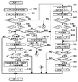
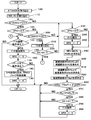
- FIG. 3 is a flowchart showing the control contents.
- step 100 the ECU 60 takes in the accelerator closing speed ⁇ TAACC based on the detection value of the accelerator sensor 57.
- the accelerator closing speed ⁇ TAACC means a change speed when the accelerator pedal 16 being depressed to a certain opening degree returns toward the fully closed position where the depression is not depressed.
- the ECU 60 can obtain this accelerator closing speed ⁇ TAACC from the change speed of the accelerator opening degree ACC.
- the ECU 60 takes in the engine rotational speed NE and the engine load KL based on the detected values of the intake pressure sensor 53, the rotational speed sensor 55 and the like.
- the ECU 60 can obtain the engine load KL from the intake pressure PM and the engine rotational speed NE.
- the ECU 60 determines whether the accelerator closing speed ⁇ TAACC is larger than the first deceleration determination value C1.
- the first deceleration determination value C1 is set to a predetermined value in order to determine the deceleration of the engine 1 early.
- the determination result is affirmative, the ECU 60 can determine that it is not the start of the deceleration of the engine 1 and shifts the processing to step 130.
- the determination result is negative, the ECU 60 can determine that the start of the deceleration of the engine 1 and shifts the processing to step 230.
- step 130 the ECU 60 determines whether the purge cut execution flag XPC is "0". As described later, the purge cut execution flag XPC is set to “1” when the purge cut (P / C) is being performed. If the determination result is affirmative, the ECU 60 can determine that the purge cut is not performed, and shifts the processing to step 140. When the determination result is negative, the ECU 60 can determine that the purge cut is being performed, and shifts the processing to step 200.
- step 140 the ECU 60 determines whether or not a predetermined fuel cut return condition necessary to execute the fuel cut (F / C) is satisfied.
- the ECU 60 shifts the processing to step 150 when the determination result is affirmative, and returns the processing to step 100 when the determination result is negative.
- the ECU 60 executes fuel cut (F / C) return. That is, the ECU 60 returns from the fuel cut to the normal fuel injection control by controlling the injectors 17.
- step 160 the ECU 60 sets the fuel cut execution flag XFC to “0” because the fuel cut is not executed.
- step 170 the ECU 60 determines whether or not a predetermined purge on condition necessary to execute the purge of the vapor is satisfied.
- the ECU 60 transfers the process to step 180 if the determination result is affirmative, and returns the process to step 100 if the determination result is negative.
- step 180 the ECU 60 takes in a predetermined target purge opening degree TPG, and restarts the purge control based on the opening degree TPG.
- the ECU 60 can obtain the target purge opening degree TPG according to the operating state of the engine 1.
- step 190 the ECU 60 sets the purge cut execution flag XPC to “0”, and returns the process to step 100.
- step 200 the ECU 60 determines whether the accelerator closing speed ⁇ TAACC is larger than a second deceleration determination value C2 (C2> C1).
- the accelerator closing speed ⁇ TAACC the first deceleration determination value C1 is faster than the second deceleration determination value C2.
- the determination result is affirmative, the ECU 60 can determine that the engine 1 has changed to acceleration or steady operation, and shifts the processing to step 210.
- the determination result is negative, the ECU 60 can determine that the deceleration of the engine 1 is continuing, and shifts the processing to step 230.
- step 210 the ECU 60 takes in the throttle opening degree TA based on the detection value of the throttle sensor 51.
- the ECU 60 determines whether the throttle opening degree TA is larger than a predetermined deceleration release determination value D1. When the determination result is affirmative, the ECU 60 can determine that the deceleration of the engine 1 has been released, and shifts the processing to step 140. If the determination result is negative, the ECU 60 can determine that the deceleration of the engine 1 is continuing because the throttle opening degree TA is relatively small, and the process proceeds to step 230.
- step 230 the ECU 60 determines whether the purge cut execution flag XPC is "0". If the determination result is affirmative, the ECU 60 can determine that the purge cut is not performed, and shifts the processing to step 240. When the determination result is negative, the ECU 60 can determine that the purge cut is being performed, and jumps the process to step 260.
- the ECU 60 executes a purge cut (P / C). That is, the ECU 60 shuts off the purge of the vapor from the purge passage 43 to the intake passage 2 by controlling the purge pump 44 and the purge valve 45.
- step 250 the ECU 60 sets the purge cut execution flag XPC to "1".
- step 260 the ECU 60 obtains a fuel cut execution load FCKL that corresponds to the engine rotational speed NE and is the engine load KL.
- the ECU 60 can obtain the fuel cut execution load FCKL according to the engine rotational speed NE, for example, by referring to the fuel cut execution load map as shown in FIG. 4. In this map, the fuel cut execution load FCKL is set to be lower as the engine rotational speed NE becomes higher.
- step 270 the ECU 60 determines whether the current engine load KL is smaller than the fuel cut execution load FCKL.
- the ECU 60 shifts the processing to step 280 when the determination result is affirmative, and returns the processing to step 100 when the determination result is negative.
- step 280 the ECU 60 determines whether the engine rotational speed NE is higher than a predetermined value A1. This predetermined value A1 is shown in the map of FIG. If the determination result is affirmative, the ECU 60 shifts the process to step 290 because the engine rotation speed NE is relatively high, and if the determination result is negative, the engine rotation speed NE is relatively low. The process returns to step 100 from step.
- the ECU 60 executes a fuel cut (F / C). That is, the ECU 60 shuts off the fuel injection from the injector 17.
- step 300 the ECU 60 sets the fuel cut execution flag XFC to “1”, and returns the process to step 100.
- the ECU 60 purges the vapor from the purge passage 43 to the intake passage 2 when it is determined that the deceleration of the engine 1 is started based on the detected operating condition of the engine 1 during the operation of the engine 1
- the purge pump 44 and the purge valve 45 are controlled to shut off (purge cut), and then the injector 17 is controlled to shut off the fuel supply to the engine 1 (fuel cut).
- the ECU 60 controls the purge pump 44 and the purge valve 45 to purge the vapor, and then cuts the fuel when it is determined that the engine 1 is in the predetermined operating state. To control the injectors 17.
- the ECU 60 determines the start of the deceleration of the engine 1 based on the accelerator closing speed ⁇ TAACC which is the change speed of the detected accelerator opening degree ACC.
- the ECU 60 determines that the deceleration is to be started, the ECU 60 performs a purge cut of the vapor at a stretch. Thereafter, if the accelerator closing speed ⁇ TAACC is between the first deceleration determination value C1 and the second deceleration determination value C2, execution of the purge cut is continued on the assumption that the deceleration state is continued.
- the ECU 60 continues the execution of the purge cut assuming that the deceleration state continues unless the accelerator opening degree ACC exceeds the deceleration release determination value D1. It is supposed to be. Further, when the return from the fuel cut is executed in a state where the accelerator opening degree ACC does not exceed the deceleration release determination value D1, the ECU 60 restarts the purge control.
- the purge pump 44 and the purge valve 45 are controlled to quickly return to the purge rate.
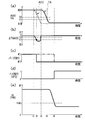
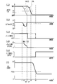
- FIG. 5 is a time chart showing the behavior of various parameters in the above-described purge control.
- (a) shows changes of the accelerator opening degree ACC (broken line) and the throttle opening degree TA (solid line).
- B) shows the change of the accelerator closing speed ⁇ TAACC.
- C) shows the change of the purge execution of vapor (a solid line shows this embodiment, a dashed-two dotted line shows a prior art example, and so on).
- D) shows a change of fuel cut (F / C) execution (fuel cut execution flag XFC).
- (E) shows the change of the engine load KL (also the change of the intake pressure PM).
- FIG. 5 shows changes of the accelerator opening degree ACC (broken line) and the throttle opening degree TA (solid line).
- B shows the change of the accelerator closing speed ⁇ TAACC.
- C shows the change of the purge execution of vapor (a solid line shows this embodiment, a dashed-two dotted line shows a prior art example, and so on
- the fuel injected from the injector 17 is supplied to the engine 1 and the vapor is purged from the purge passage 43 to the intake passage 2
- the electronic throttle device 6 is closed from the open state to the deceleration opening degree, and from the start of the deceleration, intake air including vapor remains in the intake passage 2 upstream from the electronic throttle device 6.
- This residual intake air flows to the engine 1 through the opening degree of the electronic throttle device 6 and flows to the catalysts 10 and 11 in the exhaust passage 3.
- the purge of the vapor is shut off (purge cut) first, and then the supply of fuel is shut off (fuel cut).
- the purge cut is performed before the fuel cut is performed, and the residual intake including the vapor in the intake passage 2 upstream of the electronic throttle device 6 flows to the engine 1 and is scavenged by the engine 1 until the fuel cut. Ru.
- the fuel cut is performed when the engine 1 is in a predetermined operation state (KL ⁇ FCKL, NE> A1). For this reason, it is possible to prevent the operation of the engine 1 from malfunctioning due to the execution of the fuel cut.
- the change speed of the operation amount (accelerator opening degree ACC) of the accelerator pedal 16 (accelerator closing speed ⁇ TAACC) and the change speed of the opening degree of the electronic throttle device 6 (throttle opening degree TA) The start of deceleration of the engine 1 is determined early based on Therefore, the purge cut can be performed from an early time after the start of the deceleration of the engine 1, and the wasteful increase of the vapor in the intake passage 2 upstream of the electronic throttle device 6 can be suppressed.
- the purge rate before the execution of the purge cut is promptly returned. Therefore, it is possible to suppress an excessive rise in the catalyst temperature without reducing the purge flow rate of the vapor.
- FIG. 6 is a flowchart showing the contents of the purge control.
- This embodiment differs from the configuration of the flowchart of FIG. 3 in that the processing of steps 400 and 410 is added before the processing of step 230 in the flowchart of FIG.
- step 400 the ECU 60 takes in the throttle opening degree TA based on the detection value of the throttle sensor 51.
- the ECU 60 determines whether the throttle opening degree TA is smaller than a predetermined small opening degree D2 (D2> D1). That is, after the ECU 60 determines that the deceleration of the engine 1 is started based on the accelerator closing speed ⁇ TAACC at step 120, the throttle valve 6a becomes smaller than the predetermined small opening degree D2 after the deceleration starts at this step 410. Will wait. If the determination result is affirmative, the ECU 60 shifts the process to step 230 in order to sequentially execute the purge cut and the fuel cut of the vapor. Further, when the determination result is negative, the ECU 60 returns the process to step 100.
- D2 a predetermined small opening degree D2
- the ECU 60 determines and detects the start of deceleration of the engine 1 based on the accelerator closing speed ⁇ TAACC that is the change speed of the detected accelerator opening ACC.
- the purge pump 44 and the purge valve 45 are controlled to perform the purge cut of the vapor.
- FIG. 7 is a time chart showing the behavior of various parameters in the above-described purge control.
- the types of parameters (a) to (e) are the same as those in FIG.
- the throttle opening degree TA which has started to decrease after the full closing of the accelerator opening degree ACC, has a predetermined throttle opening degree TA of (a) smaller than a predetermined small opening degree D2 at time t4.
- the purge cut is executed when the deceleration release judgment value D1 of the above is dropped. Thereafter, when the engine load KL of (e) falls below the fuel cut execution load FCKL with the throttle opening degree TA of (a) reaching the minimum deceleration opening degree at time t5, the fuel cut of (d) (F) / C) is executed.
- the purge cut is performed when the throttle opening TA falls below a predetermined deceleration release determination value D1.
- the following operations and effects can be obtained in addition to the operations and effects of the first embodiment. That is, the start of deceleration of the engine 1 is determined based on the accelerator closing speed ⁇ TAACC, and the purge cut of the vapor is performed when the throttle opening degree TA becomes smaller than the predetermined small opening degree D2. Therefore, vapor remaining in the intake passage 2 upstream of the electronic throttle device 6 flows to the engine 1 until the throttle opening degree TA becomes smaller than the predetermined small opening degree D2. Therefore, almost all the vapor remaining in the intake passage 2 upstream of the electronic throttle device 6 can be flowed to the engine 1 to be scavenged. In this case, as a result, the purge flow rate of the vapor can be increased.
- FIG. 8 is a flowchart showing the contents of the purge control.
- This embodiment differs from the configurations of the flowcharts of FIGS. 3 and 6 in that the processing of steps 420 to 440 is added before the processing of step 230 in the flowchart of FIG.
- the ECU 60 determines the small opening degree D2NE according to the engine rotational speed NE.
- the ECU 60 can obtain the small opening degree D2NE corresponding to the engine rotational speed NE, for example, by referring to the small opening degree map as shown in FIG. In this map, the small opening degree D2NE is set to increase in a curved manner as the engine rotational speed NE increases.
- step 430 the ECU 60 takes in the throttle opening degree TA based on the detection value of the throttle sensor 51.
- step 440 the ECU 60 determines whether the throttle opening degree TA is smaller than the calculated small opening degree D2NE. That is, after ECU 60 determines in step 120 that deceleration of engine 1 is to be started based on accelerator closing speed ⁇ TAACC, in step 440, throttle valve 6a has a small opening degree corresponding to engine rotational speed NE after deceleration starts. It will wait to become smaller than D2NE. If the determination result is affirmative, the ECU 60 shifts the process to step 230 in order to sequentially execute the purge cut and the fuel cut of the vapor. Further, when the determination result is negative, the ECU 60 returns the process to step 100.
- the predetermined small opening degree D2NE to be compared with the throttle opening degree TA is the engine rotational speed The higher the NE, the larger the setting.
- the following operations and effects can be obtained in addition to the operations and effects of the second embodiment. That is, the amount of the vapor remaining in the intake passage 2 upstream of the electronic throttle device 6 at the time of deceleration of the engine 1 increases to the engine 1 as the engine rotation speed NE increases.
- the predetermined small opening degree D2NE to be compared with the throttle opening degree TA is set larger as the engine rotation speed NE becomes higher. Execution time of the purge cut is adjusted. Therefore, the purge cut can be performed at an optimal timing at which the scavenging of the vapor remaining on the upstream side of the electronic throttle device 6 can be completed.
- FIG. 10 is a flowchart showing the contents of the purge control.
- the flow chart of FIG. 10 is the flow chart of FIG. 3 in that the processing of steps 450 to 480 is added between step 120 and step 230, and the processing of steps 490 and 500 is added after step 300.
- the flow chart and configuration are different.
- the process proceeds from step 120, and in step 450, the ECU 60 takes in the actual injection rate FAFVP before the deceleration fuel cut (F / C).
- the actual injection rate FAFVP is a value obtained by dividing the actual injection amount (stoichiometry) actually injected from the injector 17 by the basic injection amount (stoichiometry) with respect to the intake amount Ga.
- the ECU 60 takes in the catalyst temperature TEP.
- the ECU 60 can estimate the catalyst temperature TEP based on the fuel injection amount supplied from the injector 17 to the engine 1 or the like.
- the ECU 60 obtains an increase ⁇ TEP of the catalyst temperature from the captured actual injection rate FAFVP.
- the ECU 60 can obtain the increase ⁇ TEP of the catalyst temperature according to the actual injection rate FAFVP, for example, by referring to the catalyst temperature rise map shown in FIG. In this map, the increase ⁇ TEP in the catalyst temperature is set to decrease in a curvilinear manner as the actual injection rate FAFVP increases from “0.5” to “1.0”.
- the ECU 60 determines whether the addition result of the catalyst temperature TEP and the catalyst temperature increase ⁇ TEP is higher than a predetermined reference temperature T1.
- a predetermined reference temperature T1 for example, “750 ° C.” corresponding to the criteria for deterioration of the catalysts 10 and 11 can be applied.
- the ECU 60 shifts the processing to step 230 if the determination result is affirmative, and jumps the processing to step 260 if the determination result is negative.
- the ECU 60 executes purge cut (P / C). That is, the ECU 60 shuts off the purge of the vapor from the purge passage 43 to the intake passage 2 by controlling the purge pump 44 and the purge valve 45.
- step 500 the ECU 60 sets the purge cut execution flag XPC to “1”, and returns the process to step 100.
- the ECU 60 determines that the deceleration of the engine 1 is started during the operation of the engine 1, the ECU 60 detects the operation state of the engine 1 detected. The temperature is estimated, and the purge pump 44 and the purge valve 45 are controlled to perform vapor purge cut when the estimated temperatures of the catalysts 10 and 11 become higher than a predetermined reference temperature T1.
- the overheating of the catalysts 10 and 11 is a problem mainly because the temperature of the catalyst (the sum of the catalyst temperature TEP and the increase ⁇ TEP of the catalyst temperature) corresponds to the predetermined reference temperature T1 (for example, the criteria for catalyst deterioration It is time to get higher.
- the purge cut of vapor is executed when the estimated catalyst temperature TEP becomes higher than the predetermined reference temperature T1
- the purge cut is executed in accordance with the temperature state of the catalysts 10 and 11. Therefore, the timing of the purge cut can be extended to a temperature at which the catalysts 10 and 11 may overheat. In this case, as a result, the purge flow rate of the vapor can be increased.
- FIG. 12 is a flowchart showing the contents of the purge control.
- the flowchart of FIG. 12 omits steps 180 and 190 in the flowchart of FIG. 3, and instead provides the processing of steps 510 to 560, and performs steps 570 to 570 between steps 230 and 240 of the flowchart of FIG.
- the configuration is different from that of the flowchart of FIG. 3 in that processing of 590 is added.
- step 510 the ECU 60 takes in the target purge rate TPG%.
- the ECU 60 can obtain the target purge rate TPG% based on the operating state of the engine 1.
- step 520 the ECU 60 sets the actual actual purge rate PG% to "0".
- step 530 the ECU 60 determines the actual purge rate PG% (i) by adding a predetermined value ⁇ to the actual purge rate PG% (i-1) obtained last time, and the actual purge rate PG% ( Execute purge restart control according to i). That is, the ECU 60 controls the purge pump 44 and the purge valve 45 so that the actual purge rate PG% (i) is obtained.
- step 540 the ECU 60 determines whether the target purge rate TPG% is equal to or less than the actual purge rate PG%. If the determination result is affirmative, the ECU 60 shifts the processing to step 550 on the assumption that the purge restart is completed, and if the determination result is negative, the processing on the step 530 is regarded as incomplete purge restart. Return to.
- the ECU 60 sets the value of the target purge rate TPG% as the value of the actual purge rate PG%.
- step 560 the ECU 60 sets the purge cut execution flag XPC to “0”, assuming that the purge restart control is completed, and returns the process to step 100.
- step 230 determines whether the purge rate PG% is negative. If the determination result in step 230 is affirmative, the ECU 60 takes in the actual purge rate PG% in step 570.
- the ECU 60 determines the actual purge rate PG% (i) by subtracting the predetermined value ⁇ from the actual purge rate PG% (i-1) obtained last time, and the actual purge rate PG% ( Purge rate damping control is executed according to i). That is, the ECU 60 controls the purge pump 44 and the purge valve 45 so that the actual purge rate PG% (i) is obtained.
- step 590 the ECU 60 determines whether the actual purge rate PG% is equal to or less than "0". If the determination result is affirmative, the ECU 60 moves the process to step 240, assuming that the purge cut is completed, and if the determination result is negative, repeats the process of step 590 as the purge cut incomplete. .
- the ECU 60 performs the purge pump 44 and the purge valve 45 so that the purge rate PG% of the vapor gradually decreases when performing the purge cut of the vapor. It is supposed to control.
- the ECU 60 after performing the purge cut of the vapor in addition to the control of the first embodiment, gradually increases the purge rate PG% of the vapor when resuming the purge.
- the purge pump 44 and the purge valve 45 are controlled at the same time.
- FIG. 13 is a time chart showing the behavior of various parameters in the above-described purge control.
- (a) shows changes in the accelerator opening degree ACC (broken line) and the throttle opening degree TA (solid line).
- B) shows the change of the accelerator closing speed ⁇ TAACC.
- C) shows the change of the purge execution of vapor.
- D shows the change of the purge rate PG%.
- (E) shows a change of fuel cut (F / C) execution (fuel cut execution flag XFC).
- F) shows the change of the engine load KL (also the change of the intake pressure PM).
- the following operations and effects can be obtained in addition to the operations and effects of the first embodiment. That is, since the volume of the intake passage 2 upstream of the electronic throttle device 6 is relatively large, when the purge cut of vapor is executed at once, there is intake air remaining in the intake passage 2 upstream of the electronic throttle device 6 after the purge cut. It is difficult to predict the timing of the flow to the engine 1. On the other hand, since the engine 1 is operated by the fuel injected from the injector 17 and the vapor to be purged, the air-fuel ratio becomes over-leaned when the vapor is lost at a stroke by execution of the purge cut, and the engine 1 is misfired.
- the purge rate PG% is adjusted so as to gradually decrease, so that the vapor flowing to the engine 1 does not disappear at a stretch. Therefore, it is possible to prevent the air-fuel ratio from being over-leaned or the temperature of the catalysts 10, 11 from rising due to the execution of the purge cut when the engine is decelerating.
- the purge rate PG% is adjusted to gradually increase, so that the vapor flowing to the engine 1 does not increase at a stretch. For this reason, it is possible to prevent the air-fuel ratio from becoming over-rich and the exhaust emission from deteriorating due to the restart of the purge at the time of operation of the engine.
- FIG. 14 shows the contents of the purge control in the form of a flowchart.
- the flowchart of FIG. 14 differs from the flowchart of FIG. 3 in that the process of steps 600 to 630 is provided between step 260 and step 270 in the flowchart of FIG.
- step 600 the ECU 60 obtains the outlet pressure (compressor outlet pressure) PC of the compressor 5a just before deceleration from the engine rotational speed NE just before deceleration and the engine load KL.
- the ECU 60 can obtain the compressor outlet pressure PC immediately before deceleration according to the engine rotational speed NE immediately before deceleration and the engine load KL, for example, by referring to the outlet pressure map as shown in FIG.
- FIG. 16 is a graph showing the relationship between the compressor outlet pressure PC immediately before deceleration and the residual intake air amount VGa immediately after deceleration.
- the residual intake air amount VGa in the non-supercharged region from low pressure to atmospheric pressure, the residual intake air amount VGa becomes a predetermined constant a regardless of the compressor outlet pressure PC, and in the supercharged region, the compressor outlet pressure PC increases. It increases linearly with it.
- the ECU 60 can obtain the residual intake amount VGa immediately after deceleration according to the compressor outlet pressure PC immediately before deceleration by referring to the characteristic map according to the characteristics of the graph shown in FIG.
- the ECU 60 obtains an integrated passing intake amount TGaT that has passed through the throttle valve 6a after the start of deceleration.
- the ECU 60 can obtain the integrated passing intake amount TGaT by integrating the intake amount Ga per unit time detected by the air flow meter 52 from the start of deceleration.
- the ECU 60 determines whether the calculated value obtained by adding a predetermined value ⁇ to the difference between the residual intake amount VGa and the integrated passage intake amount TGaT is equal to or less than “0”.
- the ECU 60 determines the scavenging state of the remaining intake air in the intake passage 2 upstream of the electronic throttle device 6. If the determination result is affirmative, the ECU 60 assumes that scavenging of residual intake air has been completed, and the process proceeds to step 270. If the determination result is negative, scavenging of residual intake air is not completed. The process returns to step 100 as.
- the ECU 60 controls the purge pump 44 and the purge valve 45 in order to purge the vapor in addition to the control of the first embodiment, and then based on the operating state of the engine 1 detected.
- the fuel cut is determined after determining the residual intake amount VGa including residual air remaining in the intake passage 2 upstream of the electronic throttle device 6 (residual intake amount) VGa and determining that scavenging of the residual intake of that amount is completed.
- the injectors 17 are controlled.
- FIG. 17 is a time chart showing the behavior of various parameters in the above-described purge control.
- (a) shows changes of the accelerator opening degree ACC (broken line) and the throttle opening degree TA (solid line).
- B) shows the change of the accelerator closing speed ⁇ TAACC.
- C) shows the change of the purge execution of vapor.
- (D) shows a change of fuel cut (F / C) execution (fuel cut execution flag XFC).
- E) shows the change of the integrated passing intake amount TGaT (reduction of the residual intake amount VGa).
- (F) shows the change of the engine load KL (also the change of the intake pressure PM).
- FIG. 17 shows changes of the accelerator opening degree ACC (broken line) and the throttle opening degree TA (solid line).
- B shows the change of the accelerator closing speed ⁇ TAACC.
- C shows the change of the purge execution of vapor.
- (D) shows a change of fuel cut (F / C) execution (fuel cut execution flag
- the residual intake amount VGa decreases, the residual intake disappears (scavenging completion), and the engine load KL is a fuel cut execution load in a state in which the throttle valve 6a is closed to the deceleration opening after the accelerator opening ACC is fully closed. It can be seen that a fuel cut is carried out at once if it is below FCKL.
- the following operations and effects can be obtained in addition to the operations and effects of the first embodiment. That is, after the purge cut of the vapor is performed, the residual intake amount VGa including the vapor remaining in the intake passage 2 upstream of the electronic throttle device 6 is determined, and after scavenging of the residual intake of the amount VGa is completed, A fuel cut is performed. Therefore, the purge cut is performed, and the fuel cut is performed after the residual intake including the vapor is surely eliminated from the intake passage 2 upstream of the electronic throttle device 6.
- the present embodiment differs from the sixth embodiment in the content of the purge control.
- 18 and 19 show the contents of the purge control in the form of flowcharts. 18 and 19 adds the processing of step 640 and step 650 between step 120 and step 230 in the flowchart of FIG. 14, and step 700 between step 630 and step 270 of the flowchart of FIG.
- the configuration is different from that of the flowchart of FIG. 14 in that the processing of step 820 is added.
- step 640 the ECU 60 takes in a purge cut delay time KP described later after the deceleration determination in step 120.
- step 650 the ECU 60 shifts the process to step 230 after waiting for the purge cut delay time KP to elapse after the deceleration determination.
- step 630 determines an air-fuel ratio correction coefficient FAF at stoichiometry in step 700.
- the ECU 60 can obtain the air-fuel ratio correction coefficient FAF based on the oxygen concentration Ox detected by the oxygen sensor 56 in air-fuel ratio control of the engine 1 which is separately executed.
- the ECU 60 determines whether the air-fuel ratio correction flag XFAF is "0".
- the flag XFAF is set to "1" when the air-fuel ratio correction coefficient FAF converges to a certain value due to the purge cut of the vapor as described later.
- the ECU 60 shifts the processing to step 720 when the determination result is affirmative, and jumps the processing to step 270 when the determination result is negative.
- step 720 the ECU 60 determines whether there is a change in the air-fuel ratio correction coefficient FAF.
- the ECU 60 shifts the process to step 730 when the determination result is affirmative, and shifts the process to step 790 when the determination result is negative.
- step 730 the ECU 60 determines whether the air-fuel ratio correction coefficient FAF has been increased.
- the ECU 60 shifts the process to step 740 if the determination result is affirmative, and jumps the process to step 270 if the determination result is negative.
- the ECU 60 determines whether the change of the air-fuel ratio correction coefficient FAF has converged to a certain value.
- the ECU 60 shifts the processing to step 750 when the determination result is affirmative, and jumps the processing to step 270 when the determination result is negative.
- step 750 the ECU 60 determines whether a fuel cut (F / C) has been performed within "one second" after the convergence of the air-fuel ratio correction coefficient FAF.
- the ECU 60 transfers the process to step 760 if the determination result is affirmative, and transfers the process to step 780 if the determination result is negative.
- the ECU 60 calculates a purge cut delay time KP.
- the previous purge cut delay time KP (i-1) is taken as the current purge cut delay time KP.
- step 770 the ECU 60 sets the air-fuel ratio correction flag XFAF to "1", and then shifts the processing to step 270.
- step 780 the ECU 60 calculates the purge cut delay time KP.
- the result of adding “0.5 seconds” to the previous purge cut delay time KP (i ⁇ 1) is taken as the current purge cut delay time KP. "0.5 seconds" of the addition value is an example.
- the ECU 60 transfers the process to step 770.
- step 790 after transitioning from step 720, the ECU 60 determines whether fuel cut (F / C) has been performed without changing the air-fuel ratio correction coefficient FAF.
- the ECU 60 shifts the processing to step 800 when the determination result is affirmative, and shifts the processing to step 770 when the determination result is negative.
- the ECU 60 calculates a purge cut delay time KP.
- the result of subtracting “0.5 seconds” from the previous purge cut delay time KP (i ⁇ 1) is taken as the current purge cut delay time KP.
- the subtraction value “0.5 seconds” is an example.
- the ECU 60 determines whether the purge cut delay time KP is smaller than "0", that is, a negative value.
- the ECU 60 transfers the process to step 820 if the determination result is affirmative, and transfers the process to step 770 if the determination result is negative.
- step 820 the ECU 60 sets the purge cut delay time KP to "0", and then shifts the processing to step 770.
- the ECU 60 determines the purge cut delay time KP for delaying the purge cut of the vapor based on the detected change in the air fuel ratio (air fuel ratio correction coefficient FAF)
- the purge pump 44 and the purge valve 45 are controlled to perform the purge cut of the vapor after the purge cut delay time KP elapses.
- FIG. 20 is a time chart showing the behavior of various parameters in the above-described purge control.
- (a) shows changes of the accelerator opening degree ACC (broken line) and the throttle opening degree TA (solid line).
- B) shows the change of the accelerator closing speed ⁇ TAACC.
- C) shows the change of the purge execution of vapor.
- (D) shows a change of fuel cut (F / C) execution (fuel cut execution flag XFC).
- E) shows the change of the integrated passing intake amount TGaT (reduction of the residual intake amount VGa).
- (F) shows the change of the air-fuel ratio correction coefficient FAF.
- (G) shows the change of the engine load KL (also the change of the intake pressure PM).
- the convergence of the air-fuel ratio of the engine 1 is caused by the scavenging condition of the intake (residual intake) including the vapor remaining in the intake passage 2 upstream of the electronic throttle device 6 when the engine 1 decelerates.
- the next purge cut timing is delayed by the purge cut delay time KP from the judgment of the deceleration start.
- the following operations and effects can be obtained in addition to the operations and effects of the sixth embodiment. That is, if the purge cut is performed too early, this leads to a decrease in the flow rate of the purge supplied to the engine 1, and if the purge cut is performed too late, this will lead to an increase in the catalyst temperature.
- the timing at which the temperature of the catalyst 10, 11 rises due to the inflow of the vapor is predicted by the purge cut delay time KP. Then, after the purge cut delay time KP has elapsed, the purge cut of the vapor is executed.
- the execution timing of the purge cut is adjusted in accordance with the timing of the temperature rise of the catalysts 10 and 11. Therefore, since the execution time of the purge cut can be optimized in accordance with the temperature rise of the catalysts 10 and 11, it is possible to achieve both the suppression of the purge flow rate decrease and the suppression of the temperature rise of the catalysts 10 and 11.
- the start of deceleration of the engine 1 is determined based on the accelerator closing speed ⁇ TAACC, which is the change speed of the accelerator opening ACC, but the change speed of the throttle opening TA detected by the accelerator sensor 57 It is also possible to determine the start of deceleration of the engine 1 based on the above.
- the engine system is embodied in an engine system not provided with an EGR device.
- the engine system may be embodied in an engine system provided with an EGR device.
- the disclosed technology can be applied to an engine system provided with an engine, a supercharger, an intake amount adjustment valve, and an evaporative fuel processing device.
Landscapes
- Engineering & Computer Science (AREA)
- Chemical & Material Sciences (AREA)
- Combustion & Propulsion (AREA)
- Mechanical Engineering (AREA)
- General Engineering & Computer Science (AREA)
- Supplying Secondary Fuel Or The Like To Fuel, Air Or Fuel-Air Mixtures (AREA)
- Supercharger (AREA)
- Output Control And Ontrol Of Special Type Engine (AREA)
- Electrical Control Of Air Or Fuel Supplied To Internal-Combustion Engine (AREA)
- Combined Controls Of Internal Combustion Engines (AREA)
Abstract
エンジンシステムは、エンジン1と、インジェクタ17と、過給機5(コンプレッサ5aを含む。)と、吸気通路2に設けられた電子スロットル装置6と、コンプレッサ5aが電子スロットル装置6より上流の吸気通路2に設けられることと、蒸発燃料処理装置41(キャニスタ42、パージ通路43及びパージ弁45を含む。)と、パージ通路43の出口43aがコンプレッサ5aより上流の吸気通路2に接続されることと、電子制御装置(ECU)60とを備える。ECU60は、エンジン1の減速開始と判断したとき、パージ通路43から吸気通路2へのベーパのパージカットを実行するためにパージ弁45を制御し、その後、エンジン1への燃料カットを実行するためにインジェクタ17を制御する。
Description
この明細書に開示される技術は、過給機を備えたエンジンと、エンジンの吸気量を調節する吸気量調節弁と、燃料タンクで発生する蒸発燃料を処理する蒸発燃料処理装置とを備え、エンジンの減速時に吸気量調節弁及び蒸発燃料処理装置を制御するように構成したエンジンシステムに関する。
従来、この種の技術として、例えば、下記の特許文献1に記載される技術「過給機付内燃機関」が知られている。この技術は、過給機を備えたエンジンと、エンジンの吸気量を調節する電子スロットル装置と、電子スロットル装置より下流へ新気を導入する新気導入装置(新気導入通路と新気導入弁を含む。)と、エンジンから排出される排気の一部をEGRガスとしてエンジンへ還流するEGR装置(EGR通路とEGR弁を含む。)と、新気導入通路から分岐する漏れEGRバイパス通路とを備える。この構成において、電子スロットル装置より下流の吸気通路から新気導入通路へEGRガスが漏れ流れた場合、そのEGRガスを漏れEGRバイパス通路を介してEGR通路の出口より上流の吸気通路へ掃気することで、新気導入弁の機能を維持するようになっている。
ところで、特許文献1に記載される技術においても、燃料タンクで発生する蒸発燃料(ベーパ)を処理する蒸発燃料処理装置(キャニスタ、パージ通路及びパージ弁を含む。)を設けることが考えられる。この場合、過給機付きエンジンでは、キャニスタから流れ出たベーパを吸気通路へ導出するパージ通路の出口は、過給機(コンプレッサ)より上流の吸気通路に設けられることが多い。この場合、パージ通路の出口からエンジンまでの吸気通路の経路が長くなり、容積も大きくなる傾向がある。ここで、一般に、エンジンの減速時には、エンジンへの燃料供給を遮断(燃料カット)することがあるが、通常は、燃料カットと同時に、パージ通路から吸気通路へのベーパのパージを遮断(パージカット)することが行われる。これは、燃料カットが実行されるときにベーパのパージが継続すると、そのベーパ(未燃の燃料を含む)がエンジンを介して排気通路の触媒へ流れ、触媒の温度が過剰に上昇するおそれがあり、この事態を回避するためである。
ところが、上記した過給機付きエンジンに蒸発燃料処理装置を設けたエンジンシステムでは、エンジンの減速時に、電子スロットル装置が所定の減速開度まで閉じると、電子スロットル装置より上流の吸気通路にベーパを含む吸気が大量に残留し、その残留吸気が電子スロットル装置の微小開度を通じてエンジンへ流れ、触媒に流入するおそれがある。そのため、減速時に燃料カットと同時にパージカットしても、触媒にベーパを含む残留吸気が流入し続け、触媒の温度が過剰に上昇して触媒が過熱により劣化又は溶損するおそれがある。
この開示技術は、上記事情に鑑みてなされたものであって、その目的は、過給機より下流の吸気通路に設けられる吸気量調節弁と、燃料タンクで発生する蒸発燃料を過給機より上流の吸気通路へパージする蒸発燃料処理装置とを備え、エンジンの減速時に燃料カットを実行するときに、エンジンから触媒への蒸発燃料の流入を抑えて触媒の温度の過剰な上昇を防止することを可能としたエンジンシステムを提供することにある。
(1)上記目的を達成するために、本願開示技術の一態様は、エンジンと、エンジンへ吸気を導入するための吸気通路と、エンジンから排気を導出するための排気通路と、燃料を貯留するための燃料タンクと、燃料タンクに貯留された燃料を噴射するためのインジェクタとを含み、エンジンへ燃料を供給するための燃料供給装置と、吸気通路に配置され、吸気通路を流れる吸気量を調節するための吸気量調節弁と、吸気通路に配置されたコンプレッサと、排気通路に配置されたタービンと、コンプレッサとタービンを一体回転可能に連結する回転軸とを含み、吸気通路における吸気を昇圧させるための過給機と、燃料タンクで発生する蒸発燃料を一旦捕集するためのキャニスタと、キャニスタで捕集された蒸発燃料を吸気通路へパージするためのパージ通路と、パージ通路は、その出口がコンプレッサより上流の吸気通路に接続されることと、パージ通路から吸気通路へパージされる蒸発燃料量を調節するためのパージ調節手段とを含み、蒸発燃料を処理するための蒸発燃料処理装置と、エンジンの運転状態を検出するための運転状態検出手段と、検出されるエンジンの運転状態に応じて、少なくともインジェクタ、吸気量調節弁及びパージ調節手段を制御するための制御手段とを備えたエンジンシステムにおいて、制御手段は、エンジンの運転時に、検出されるエンジンの運転状態に基づきエンジンの減速開始と判断したとき、パージ通路から吸気通路への蒸発燃料のパージを遮断するためにパージ調節手段を制御し、その後、エンジンへの燃料の供給を遮断するためにインジェクタを制御することを趣旨とする。
上記(1)の構成によれば、インジェクタから噴射される燃料がエンジンへ供給され、かつ、蒸発燃料がパージ通路から吸気通路へパージされる状態からのエンジンの減速時には、吸気量調節弁が開弁状態から減速開度へ閉弁され、その減速開始から、吸気量調節弁より上流の吸気通路には、蒸発燃料を含む吸気が残留する。この残留吸気は、吸気量調節弁の微少開度を通じてエンジンへ流れて排気通路の触媒へ流れる。ここで、エンジンの減速開始と判断されたときは、最初に蒸発燃料のパージが遮断(パージカット)され、その後、燃料の供給が遮断(燃料カット)される。従って、燃料カットが実行される前にパージカットが実行され、燃料カットまでに吸気量調節弁より上流の蒸発燃料を含む残留吸気がエンジンへ流れて掃気され、エンジンで燃焼される。これにより、燃料カットが実行された後に触媒へ流れる蒸発燃料が無くなる。
(2)上記目的を達成するために、上記(1)の構成において、制御手段は、蒸発燃料のパージを遮断するためにパージ調節手段を制御した後、エンジンが所定の運転状態になったと判断したときに、燃料の供給を遮断するためにインジェクタを制御することを趣旨とする。
上記(2)の構成によれば、上記(1)の構成の作用に加え、パージカットが実行された後に、エンジンが所定の運転状態となったときに燃料カットが実行される。
(3)上記目的を達成するために、上記(1)又は(2)の構成において、制御手段は、蒸発燃料のパージを遮断するためにパージ調節手段を制御した後、検出される運転状態に基づいて、吸気量調節弁より上流の吸気通路に残留する蒸発燃料を含む残留吸気の量を求め、その量の残留吸気の掃気が完了したと判断してから、燃料の供給を遮断するためにインジェクタを制御することを趣旨とする。
上記(3)の構成によれば、上記(1)又は(2)の構成の作用に加え、蒸発燃料のパージカットが実行された後、吸気量調節弁より上流の吸気通路に残留する蒸発燃料を含む残留吸気の量が求められ、その量の残留吸気の掃気が完了してから、燃料カットが実行される。従って、パージカットが実行され、吸気量調節弁より上流の吸気通路から蒸発燃料を含む残留吸気が確実に無くなってから燃料カットが実行される。
(4)上記目的を達成するために、上記(1)又は(2)の構成において、制御手段は、エンジンの運転時にエンジンの減速開始と判断したとき、検出されるエンジンの運転状態に基づき触媒の温度を推定し、推定された触媒の温度が所定の基準温度より高くなったときに蒸発燃料のパージを遮断するためにパージ調節手段を制御することを趣旨とする。
上記(4)の構成によれば、上記(1)又は(2)の構成の作用に加え、触媒の過熱が問題になるのは、主として触媒の温度が所定の基準温度より高くなるときである。ここでは、推定された触媒の温度が所定の基準温度より高くなったときに蒸発燃料のパージカットが実行されるので、触媒の温度状態に合わせてパージカットが実行される。
(5)上記目的を達成するために、上記(1)又は(2)の構成において、運転状態検出手段は、エンジンの空燃比を検出するための空燃比検出手段を含み、制御手段は、検出される空燃比の変化に基づき蒸発燃料のパージの遮断を遅延させる遅延時間を求め、エンジンの運転時にエンジンの減速開始と判断したとき、遅延時間が経過してから蒸発燃料のパージを遮断するためにパージ調節手段を制御することを趣旨とする。
上記(5)の構成によれば、上記(1)又は(2)の構成の作用に加え、エンジンの空燃比の変化から、蒸発燃料の流入により触媒の温度が上昇するタイミングが遅延時間によって予測される。そして、その遅延時間が経過してから蒸発燃料のパージカットが実行される。従って、触媒の温度上昇のタイミングに合わせてパージカットの実行時期が調整される。
(6)上記目的を達成するために、上記(1)又は(2)の構成において、制御手段は、蒸発燃料のパージを遮断するときは、蒸発燃料のパージ率が徐々に減少するようにパージ調節手段を制御することを趣旨とする。
上記(6)の構成によれば、上記(1)又は(2)の構成の作用に加え、蒸発燃料のパージカットが実行されるときに、そのパージ率が徐々に減少するように調節されるので、エンジンへ流れる蒸発燃料が一気に無くなることがない。
(7)上記目的を達成するために、上記(6)の構成において、制御手段は、蒸発燃料のパージを遮断した後、蒸発燃料のパージを再開するときは、蒸発燃料のパージ率が徐々に増加するようにパージ調節手段を制御することを趣旨とする。
上記(7)の構成によれば、上記(7)の構成の作用に加え、蒸発燃料のパージを再開するときに、蒸発燃料のパージ率が徐々に増加するように調節されるので、エンジンへ流れる蒸発燃料が一気に増加することがない。
(8)上記目的を達成するために、上記(1)乃至(7)のいずれかの構成において、エンジンの出力を制御するために運転者が操作する出力操作手段を更に備え、運転状態検出手段は、出力操作手段の操作量を検出するための出力操作量検出手段と、吸気量調節弁の開度を検出するための弁開度検出手段とを含み、制御手段は、検出される操作量の変化速度及び検出される開度の変化速度の少なくとも一方に基づきエンジンの減速開始を判断することを趣旨とする。
上記(8)の構成によれば、上記(1)乃至(7)のいずれかの構成の作用に加え、出力操作手段の操作量の変化速度及び吸気量調節弁の開度の変化速度の少なくとも一方に基づきエンジンの減速開始が早期に判断される。
(9)上記目的を達成するために、上記(8)の構成において、制御手段は、検出される操作量の変化速度に基づきエンジンの減速開始を判断し、かつ、検出される開度が所定の小開度より小さいと判断したときに、蒸発燃料のパージを遮断するためにパージ調節手段を制御することを趣旨とする。
上記(9)の構成によれば、上記(8)の構成の作用に加え、出力操作手段の操作量の変化速度に基づきエンジンの減速開始が判断され、かつ、吸気量調節弁の開度が所定の小開度より小さくなったときに、蒸発燃料のパージカットが実行される。従って、吸気量調節弁の開度が所定の小開度より小さくなるまで、吸気量調節弁より上流の吸気通路に残留する蒸発燃料がエンジンへ流れる。
(10)上記目的を達成するために、上記(9)の構成において、運転状態検出手段は、エンジンの回転速度を検出するための回転速度検出手段を含み、制御手段は、検出される回転速度が高くなるほど所定の小開度を大きく設定することを趣旨とする。
上記(10)の構成によれば、上記(9)の構成の作用に加え、エンジンの減速時に吸気量調節弁より上流の吸気通路に残留する蒸発燃料がエンジンへ流れる量は、エンジンの回転速度が高くなるほど多くなる。ここでは、エンジンの減速開始が判断されたとき、吸気量調節弁の開度と比較されるべき所定の小開度が、エンジンの回転速度が高くなるほど大きく設定されるので、エンジンの回転速度に合わせてパージカットの実行時期が調整される。
上記(1)の構成によれば、過給機より下流の吸気通路に設けられる吸気量調節弁と、燃料タンクで発生する蒸発燃料を過給機より上流の吸気通路へパージする蒸発燃料処理装置とを備えたエンジンシステムにおいて、エンジンの減速時に燃料カットを実行するときに、エンジンから触媒への蒸発燃料の流入を抑えることができ、触媒の温度の過剰な上昇を防止することができる。
上記(2)の構成によれば、上記(1)の構成の効果に加え、燃料カットの実行によりエンジンの運転が不調となることを防止することができる。
上記(3)の構成によれば、上記(1)又は(2)の構成の効果に加え、エンジンの減速時に燃料カットを実行するときに、エンジンから触媒への蒸発燃料の流入をより確実に抑えることができ、触媒の温度の過剰な上昇を精度良く防止することができる。
上記(4)の構成によれば、上記(1)又は(2)の構成の効果に加え、実際に触媒に過熱のおそれがある温度までパージカットのタイミングを延長することができる。この場合、結果的に蒸発燃料のパージ流量を増加させることができる。
上記(5)の構成によれば、上記(1)又は(2)の構成の効果に加え、パージカットの実行時期を触媒の温度に合わせて最適化することができるので、パージ流量の低下抑制と触媒の温度上昇抑制の両立を図ることができる。
上記(6)の構成によれば、上記(1)又は(2)の構成の効果に加え、エンジンの減速時にパージカットの実行により空燃比がオーバーリーン化したり、触媒が温度上昇したりすることを防止することができる。
上記(7)の構成によれば、上記(6)の構成の効果に加え、エンジン1の運転時にパージ再開により空燃比がオーバーリッチ化したり、排気エミッションが悪化したりすることを防止することができる。
上記(8)の構成によれば、上記(1)乃至(7)のいずれかの構成の効果に加え、エンジンの減速開始後の早い時期からパージカットを実行することができ、吸気量調節弁より上流の吸気通路における蒸発燃料の無駄な増加を抑えることができる。
上記(9)の構成によれば、上記(8)の構成の効果に加え、吸気量調節弁より上流の吸気通路に残留する蒸発燃料の殆ど全てをエンジンへ流して掃気することができる。この場合、結果的に蒸発燃料のパージ流量を増加させることができる。
上記(10)の構成によれば、上記(9)の構成の効果に加え、吸気量調節弁より上流に残留する蒸発燃料の掃気を完了できる最適なタイミングでパージカットを実行することができる。
<第1実施形態>
以下、エンジンシステムを具体化した第1実施形態につき図面を参照して詳細に説明する。
以下、エンジンシステムを具体化した第1実施形態につき図面を参照して詳細に説明する。
[エンジンシステムの概要について]
図1に、この実施形態のエンジンシステムを概略構成図により示す。自動車に搭載されたガソリンエンジンシステム(以下、単に「エンジンシステム」と言う。)は、複数の気筒を有するエンジン1を備える。このエンジン1は、4気筒、4サイクルのレシプロエンジンであり、後述するピストン19及びクランクシャフト20(図2参照)等の周知な構成を含む。エンジン1には、各気筒へ吸気を導入するための吸気通路2と、各気筒から排気を導出するための排気通路3が設けられる。吸気通路2と排気通路3には、過給機5が設けられる。吸気通路2には、その上流側から順に吸気入口2a、エアクリーナ4、過給機5のコンプレッサ5a、電子スロットル装置6、インタークーラ7及び吸気マニホールド8が設けられる。
図1に、この実施形態のエンジンシステムを概略構成図により示す。自動車に搭載されたガソリンエンジンシステム(以下、単に「エンジンシステム」と言う。)は、複数の気筒を有するエンジン1を備える。このエンジン1は、4気筒、4サイクルのレシプロエンジンであり、後述するピストン19及びクランクシャフト20(図2参照)等の周知な構成を含む。エンジン1には、各気筒へ吸気を導入するための吸気通路2と、各気筒から排気を導出するための排気通路3が設けられる。吸気通路2と排気通路3には、過給機5が設けられる。吸気通路2には、その上流側から順に吸気入口2a、エアクリーナ4、過給機5のコンプレッサ5a、電子スロットル装置6、インタークーラ7及び吸気マニホールド8が設けられる。
電子スロットル装置6は、吸気マニホールド8及びインタークーラ7より上流の吸気通路2に配置され、運転者によるアクセル操作に応じて開閉駆動されることで、吸気通路2を流れる吸気量を調節するようになっている。一例として、電子スロットル装置6は、モータ方式の電動弁により構成され、モータ(図示略)により開閉駆動されるスロットル弁6aと、スロットル弁6aの開度(スロットル開度)TAを検出するためのスロットルセンサ51とを含む。スロットルセンサ51は、この開示技術における弁開度検出手段の一例に相当する。電子スロットル装置6は、この開示技術における吸気量調節弁の一例に相当する。吸気マニホールド8は、エンジン1の直上流に配置され、吸気が導入されるサージタンク8aと、サージタンク8aに導入された吸気をエンジン1の各気筒へ分配するための複数(4つ)の分岐管8bとを含む。排気通路3には、その上流側から順に排気マニホールド9、過給機5のタービン5b及び直列に配置された二つの触媒10,11が設けられる。二つの触媒10,11は、排気を浄化するためのものであり、例えば、三元触媒により構成することができる。
過給機5は、吸気通路2における吸気を昇圧するために設けられ、一例として、吸気通路2に配置されたコンプレッサ5aと、排気通路3に配置されたタービン5bと、コンプレッサ5aとタービン5bを一体回転可能に連結する回転軸5cとを含む。タービン5bが、排気通路3を流れる排気により回転動作し、それに連動してコンプレッサ5aが回転動作することにより、吸気通路2を流れる吸気が昇圧されるようになっている。インタークーラ7は、コンプレッサ5aで昇圧された吸気を冷却するようになっている。
図2に、エンジン1の概略を断面図により示す。図2に示すように、エンジン1には、各気筒に対応して燃料を噴射するためのインジェクタ17が設けられる。インジェクタ17は、燃料を貯留するための燃料タンク40(図1参照)から供給される燃料をエンジン1の各気筒へ噴射するように構成される。各気筒では、インジェクタ17から噴射される燃料と吸気マニホールド8から導入される吸気とにより可燃混合気が形成される。インジェクタ17と燃料タンク40は、この開示技術における燃料供給装置を構成する要素の一例である。
図2に示すように、エンジン1には、各気筒に対応して点火装置18が設けられる。点火装置18は、各気筒で形成される可燃混合気に点火するように構成される。各気筒内の可燃混合気は、点火装置18の点火動作により爆発・燃焼し、燃焼後の排気は、各気筒から排気マニホールド9、タービン5b及び各触媒10,11を経て外部へ排出される。このとき、各気筒では、ピストン19が上下運動し、クランクシャフト20が回転することにより、エンジン1に動力が得られる。
[蒸発燃料処理装置について]
この実施形態において、図1に示すように、燃料供給装置は燃料を貯留するための燃料タンク40を備える。また、このエンジンシステムは、燃料タンク40で発生する蒸発燃料(ベーパ)を大気へ放出させることなく捕集して処理するための蒸発燃料処理装置41を備える。この装置41は、キャニスタ42、パージ通路43、パージポンプ44及びパージ弁45を含む。キャニスタ42は、燃料タンク40で発生するベーパを、ベーパ通路46を通じて一旦捕集するようになっている。キャニスタ42は、ベーパを吸着する吸着剤(図示略)を内蔵する。パージ通路43は、キャニスタ42から延び、その出口43aは、コンプレッサ5aより上流の吸気通路2に接続される。一例として、パージポンプ44とパージ弁45は、それぞれ電動式の構成を有し、パージ通路43に設けられる。パージポンプ44は、キャニスタ42からベーパを吸引してパージ通路43へ吐出するようになっている。パージ弁45は、パージ通路43におけるベーパ流量を調節するようになっている。キャニスタ42に設けられる大気口42aは、ベーパがパージ通路43へパージされるときに、キャニスタ42へ大気を導入するようになっている。パージポンプ44及びパージ弁45は、この開示技術におけるパージ調節手段の一例に相当する。
この実施形態において、図1に示すように、燃料供給装置は燃料を貯留するための燃料タンク40を備える。また、このエンジンシステムは、燃料タンク40で発生する蒸発燃料(ベーパ)を大気へ放出させることなく捕集して処理するための蒸発燃料処理装置41を備える。この装置41は、キャニスタ42、パージ通路43、パージポンプ44及びパージ弁45を含む。キャニスタ42は、燃料タンク40で発生するベーパを、ベーパ通路46を通じて一旦捕集するようになっている。キャニスタ42は、ベーパを吸着する吸着剤(図示略)を内蔵する。パージ通路43は、キャニスタ42から延び、その出口43aは、コンプレッサ5aより上流の吸気通路2に接続される。一例として、パージポンプ44とパージ弁45は、それぞれ電動式の構成を有し、パージ通路43に設けられる。パージポンプ44は、キャニスタ42からベーパを吸引してパージ通路43へ吐出するようになっている。パージ弁45は、パージ通路43におけるベーパ流量を調節するようになっている。キャニスタ42に設けられる大気口42aは、ベーパがパージ通路43へパージされるときに、キャニスタ42へ大気を導入するようになっている。パージポンプ44及びパージ弁45は、この開示技術におけるパージ調節手段の一例に相当する。
この蒸発燃料処理装置41によれば、エンジン1の運転時に、吸気通路2で発生する負圧がパージ通路43等を通じてキャニスタ42に作用するときに、パージポンプ44及びパージ弁45を作動させることで、キャニスタ42に捕集されたベーパをパージ通路43を通じて吸気通路2へパージするようになっている。パージされたベーパは、エンジン1に吸入されて燃焼に供され、処理されることになる。
[エンジンシステムの電気的構成について]
図1に示すように、このエンジンシステムに設けられる各種センサ等51~58は、エンジン1の運転状態を検出するためのこの開示技術における運転状態検出手段の一例に相当する。エアクリーナ4の近傍に設けられるエアフローメータ52は、エアクリーナ4から吸気通路2へ流れる吸気量Gaを検出し、その検出値に応じた電気信号を出力する。サージタンク8aに設けられる吸気圧センサ53は、電子スロットル装置6より下流の吸気圧力PMを検出し、その検出値に応じた電気信号を出力する。エンジン1に設けられる水温センサ54は、エンジン1の内部を流れる冷却水の温度(冷却水温度)THWを検出し、その検出値に応じた電気信号を出力する。エンジン1に設けられる回転速度センサ55は、クランクシャフト20の回転速度をエンジン1の回転速度(エンジン回転速度)NEとして検出し、その検出値に応じた電気信号を出力する。回転速度センサ55は、この開示技術における回転速度検出手段の一例に相当する。排気通路3に設けられる酸素センサ56は、排気通路3へ排出される排気中の酸素濃度(出力電圧)Oxを検出し、その検出値に応じた電気信号を出力する。酸素センサ56は、この開示技術における空燃比検出手段の一例に相当する。運転席に設けられるアクセルペダル16には、アクセルセンサ57が設けられる。アクセルペダル16は、この開示技術における出力操作手段の一例に相当する。アクセルセンサ57は、アクセルペダル16の踏み込み角度をアクセル開度ACCとして検出し、その検出値に応じた電気信号を出力する。アクセルセンサ57は、この開示技術における出力操作量検出手段の一例に相当する。車両に設けられる車速センサ58は、車両の走行速度(車速)SPDを検出し、その検出値に応じた電気信号を出力する。
図1に示すように、このエンジンシステムに設けられる各種センサ等51~58は、エンジン1の運転状態を検出するためのこの開示技術における運転状態検出手段の一例に相当する。エアクリーナ4の近傍に設けられるエアフローメータ52は、エアクリーナ4から吸気通路2へ流れる吸気量Gaを検出し、その検出値に応じた電気信号を出力する。サージタンク8aに設けられる吸気圧センサ53は、電子スロットル装置6より下流の吸気圧力PMを検出し、その検出値に応じた電気信号を出力する。エンジン1に設けられる水温センサ54は、エンジン1の内部を流れる冷却水の温度(冷却水温度)THWを検出し、その検出値に応じた電気信号を出力する。エンジン1に設けられる回転速度センサ55は、クランクシャフト20の回転速度をエンジン1の回転速度(エンジン回転速度)NEとして検出し、その検出値に応じた電気信号を出力する。回転速度センサ55は、この開示技術における回転速度検出手段の一例に相当する。排気通路3に設けられる酸素センサ56は、排気通路3へ排出される排気中の酸素濃度(出力電圧)Oxを検出し、その検出値に応じた電気信号を出力する。酸素センサ56は、この開示技術における空燃比検出手段の一例に相当する。運転席に設けられるアクセルペダル16には、アクセルセンサ57が設けられる。アクセルペダル16は、この開示技術における出力操作手段の一例に相当する。アクセルセンサ57は、アクセルペダル16の踏み込み角度をアクセル開度ACCとして検出し、その検出値に応じた電気信号を出力する。アクセルセンサ57は、この開示技術における出力操作量検出手段の一例に相当する。車両に設けられる車速センサ58は、車両の走行速度(車速)SPDを検出し、その検出値に応じた電気信号を出力する。
このエンジンシステムは、各種制御を司る電子制御装置(ECU)60を備える。ECU60には、各種センサ等51~58がそれぞれ接続される。また、ECU60には、電子スロットル装置6、各インジェクタ17、各点火装置18、パージポンプ44及びパージ弁45等がそれぞれ接続される。ECU60は、この開示技術における制御手段の一例に相当する。
この実施形態で、ECU60は、各種センサ等51~58から出力される各種信号を入力し、それら信号に基づいて空燃比制御を含む燃料噴射制御及び点火時期制御をそれぞれ実行するために、各インジェクタ17及び各点火装置18をそれぞれ制御するようになっている。また、ECU60は、各種信号に基づいて吸気制御及びパージ制御を実行するために、電子スロットル装置6、パージポンプ44及びパージ弁45をそれぞれ制御するようになっている。
ここで、吸気制御とは、運転者によるアクセルペダル16の操作に応じたアクセルセンサ57の検出値に基づき、電子スロットル装置6を制御することにより、エンジン1に吸入される吸気量を制御することである。ECU60は、エンジン1の減速時には、エンジン1に吸入される吸気を絞るために電子スロットル装置6(スロットル弁6a)を開弁状態から所定の微小な減速開度へ閉弁制御するようになっている。パージ制御とは、エンジン1の運転状態に応じてパージポンプ44及びパージ弁45を制御することにより、キャニスタ42から吸気通路2へのベーパのパージ流量を制御することである。
周知のようにECU60は、中央処理装置(CPU)、各種メモリ、外部入力回路及び外部出力回路等を備える。メモリには、エンジン1の各種制御に関する所定の制御プログラムが格納される。CPUは、入力回路を介して入力される各種センサ等51~58の検出値に基づき、所定の制御プログラムに基づいて前述した各種制御を実行するようになっている。
上記エンジンシステムでは、パージ通路43の出口43aから電子スロットル装置6までの吸気通路2の経路が比較的長く、その経路の容積が比較的大きくなっている。そのため、パージ実行状態からのエンジン1の減速時には、スロットル弁6aが開弁状態から所定の減速開度へ閉弁する。このときパージカットを実行しても、電子スロットル装置6からパージ通路43の出口43aまでの吸気通路2の経路が比較的長いことから、その部分にはパージカット実行前にパージされたベーパを含む吸気が残留することになる。特に過給状態からの減速時には、吸気が高密度化し、ベーパを含む残留吸気がコンプレッサ5aの上流側まで逆流して拡大することがある。そして、その残留吸気が電子スロットル装置6の微小開度を通じてエンジン1へ流れ、触媒10,11に流入するおそれがある。そのため、減速時に燃料カットと同時にパージカットしても、触媒10,11にベーパを含む残留吸気が流入し続け、触媒10,11の温度(触媒温度)が過剰に上昇して、触媒10,11が劣化又は溶損するおそれがある。そこで、この実施形態では、上記課題に対処するために、次のようなパージ制御を実行するようになっている。
[減速時のパージ制御について]
この実施形態では、エンジン1の減速時に次のようなパージ制御を実行するようになっている。図3に、その制御内容をフローチャートにより示す。
この実施形態では、エンジン1の減速時に次のようなパージ制御を実行するようになっている。図3に、その制御内容をフローチャートにより示す。
処理がこのルーチンへ移行すると、ステップ100で、ECU60は、アクセルセンサ57の検出値に基づきアクセル閉速度ΔTAACCを取り込む。アクセル閉速度ΔTAACCは、ある開度に踏み込み操作されているアクセルペダル16が、踏み込み操作されていない全閉位置へ向けて戻るときの変化速度を意味する。ECU60は、このアクセル閉速度ΔTAACCを、アクセル開度ACCの変化速度から求めることができる。
次に、ステップ110で、ECU60は、吸気圧センサ53及び回転速度センサ55等の検出値に基づき、エンジン回転速度NEとエンジン負荷KLをそれぞれ取り込む。ECU60は、エンジン負荷KLを、吸気圧力PMとエンジン回転速度NEから求めることができる。
次に、ステップ120で、ECU60は、アクセル閉速度ΔTAACCが第1減速判定値C1より大きいか否かを判断する。この第1減速判定値C1は、エンジン1の減速を早期に判定するために所定値に設定される。ECU60は、この判断結果が肯定となる場合は、エンジン1の減速の開始でないと判定することができ、処理をステップ130へ移行する。ECU60は、この判断結果が否定となる場合は、エンジン1の減速の開始であると判定することができ、処理をステップ230へ移行する。
ステップ130では、ECU60は、パージカット実行フラグXPCが「0」であるか否かを判断する。後述するように、パージカット実行フラグXPCは、パージカット(P/C)が実行されている場合に「1」に設定されるようになっている。ECU60は、この判断結果が肯定となる場合は、パージカットが実行されていないと判定することができ、処理をステップ140へ移行する。ECU60は、この判断結果が否定となる場合は、パージカットが実行されていると判定することができ、処理をステップ200へ移行する。
ステップ140では、ECU60は、燃料カット(F/C)を実行するために必要な所定の燃料カット復帰条件が成立しているか否かを判断する。ECU60は、この判断結果が肯定となる場合は処理をステップ150へ移行し、この判断結果が否定となる場合は処理をステップ100へ戻す。
ステップ150では、ECU60は、燃料カット(F/C)復帰を実行する。すなわち、ECU60は、インジェクタ17を制御することにより、燃料カットから通常の燃料噴射制御へ復帰する。
次に、ステップ160で、ECU60は、燃料カットを実行していないことから、燃料カット実行フラグXFCを「0」に設定する。
次に、ステップ170で、ECU60は、べーパのパージを実行するために必要な所定のパージオン条件が成立しているか否かを判断する。ECU60は、この判断結果が肯定となる場合は処理をステップ180へ移行し、この判断結果が否定となる場合は処理をステップ100へ戻す。
ステップ180では、ECU60は、所定の目標パージ開度TPGを取り込み、その開度TPGに基づいてパージ制御を再開する。ECU60は、エンジン1の運転状態に応じた目標パージ開度TPGを求めることができる。
次に、ステップ190で、ECU60は、パージカット実行フラグXPCを「0」に設定し、処理をステップ100へ戻す。
一方、ステップ130から移行してステップ200では、ECU60は、アクセル閉速度ΔTAACCが第2減速判定値C2(C2>C1)より大きいか否かを判断する。ここで、アクセル閉速度ΔTAACCとしては、第1減速判定値C1が第2減速判定値C2よりも速い。ECU60は、この判断結果が肯定となる場合は、エンジン1が加速又は定常の運転へ変わったと判定することができ、処理をステップ210へ移行する。ECU60は、この判断結果が否定となる場合は、エンジン1の減速が継続していると判定することができ、処理をステップ230へ移行する。
ステップ210では、ECU60は、スロットルセンサ51の検出値に基づきスロットル開度TAを取り込む。
次に、ステップ220で、ECU60は、スロットル開度TAが所定の減速解除判定値D1より大きいか否かを判断する。ECU60は、この判断結果が肯定となる場合は、エンジン1の減速が解除されたと判定することができ、処理をステップ140へ移行する。ECU60は、この判断結果が否定となる場合は、スロットル開度TAが比較的小さいことからエンジン1の減速が継続していると判定することができ、処理をステップ230へ移行する。
一方、ステップ120、ステップ200又はステップ220から移行してステップ230では、ECU60は、パージカット実行フラグXPCが「0」か否かを判断する。ECU60は、この判断結果が肯定となる場合は、パージカットが実行されていないと判定することができ、処理をステップ240へ移行する。ECU60は、この判断結果が否定となる場合は、パージカットを実行していると判定することができ、処理をステップ260へジャンプする。
ステップ240では、ECU60は、パージカット(P/C)を実行する。すなわち、ECU60は、パージポンプ44及びパージ弁45を制御することにより、パージ通路43から吸気通路2へのベーパのパージを遮断する。
次に、ステップ250で、ECU60は、パージカット実行フラグXPCを「1」に設定する。
そして、ステップ230又はステップ250から移行してステップ260では、ECU60は、エンジン負荷KLであって、エンジン回転速度NEに応じた燃料カット実行負荷FCKLを求める。ECU60は、例えば、図4に示すような燃料カット実行負荷マップを参照することにより、エンジン回転速度NEに応じた燃料カット実行負荷FCKLを求めることができる。このマップでは、エンジン回転速度NEが高くなるほど燃料カット実行負荷FCKLが低くなるように設定されている。
次に、ステップ270では、ECU60は、現在のエンジン負荷KLが燃料カット実行負荷FCKLより小さいか否かを判断する。ECU60は、この判断結果が肯定となる場合は処理をステップ280へ移行し、この判断結果が否定となる場合は処理をステップ100へ戻す。
ステップ280では、ECU60は、エンジン回転速度NEが所定値A1より高いか否かを判断する。この所定値A1を、図4のマップに示す。ECU60は、この判断結果が肯定となる場合は、エンジン回転速度NEが比較的高いことから処理をステップ290へ移行し、この判断結果が否定となる場合は、エンジン回転速度NEが比較的低いことから処理をステップ100へ戻す。
ステップ290では、ECU60は、燃料カット(F/C)を実行する。すなわち、ECU60は、インジェクタ17からの燃料噴射を遮断する。
次に、ステップ300で、ECU60は、燃料カット実行フラグXFCを「1」に設定し、処理をステップ100へ戻す。
上記したパージ制御によれば、ECU60は、エンジン1の運転時に、検出されるエンジン1の運転状態に基づきエンジン1の減速開始と判断したとき、パージ通路43から吸気通路2へのベーパのパージを遮断(パージカット)するためにパージポンプ44及びパージ弁45を制御し、その後、エンジン1への燃料の供給を遮断(燃料カット)するためにインジェクタ17を制御するようになっている。
上記したパージ制御によれば、ECU60は、ベーパのパージカットをするためにパージポンプ44及びパージ弁45を制御した後、エンジン1が所定の運転状態になったと判断したときに、燃料カットをするためにインジェクタ17を制御するようになっている。
また、上記したパージ制御によれば、ECU60は、検出されるアクセル開度ACCの変化速度であるアクセル閉速度ΔTAACCに基づきエンジン1の減速開始を判断するようになっている。そして、ECU60は、減速開始を判断したときは、ベーパのパージカットを一気に実行する。その後、アクセル閉速度ΔTAACCが第1減速判定値C1と第2減速判定値C2との間にある場合は、減速状態が継続するものとしてパージカットの実行を継続するようになっている。また、アクセル閉速度ΔTAACCが第2減速判定値C2を超えても、アクセル開度ACCが減速解除判定値D1を超えなければ、ECU60は、減速状態が継続するものとしてパージカットの実行を継続するようになっている。また、アクセル開度ACCが減速解除判定値D1を超えない状態で、燃料カットからの復帰を実行する場合は、ECU60は、パージ制御を再開するようになっている。
更に、上記したパージ制御によれば、ECU60は、それぞれ検出されるアクセル閉速度ΔTAACCとスロットル開度TAに基づき、エンジン1の減速途中で、減速が中止になった場合は、パージカット実行前のパージ率に速やかに戻すためにパージポンプ44及びパージ弁45を制御するようになっている。
ここで、図5に、上記したパージ制御における各種パラメータの挙動をタイムチャートにより示す。図5において、(a)はアクセル開度ACC(破線)と、スロットル開度TA(実線)の変化を示す。(b)はアクセル閉速度ΔTAACCの変化を示す。(c)はベーパのパージ実行の変化を示す(実線は本実施形態を示し、2点鎖線は従来例を示す。以下同様)。(d)は燃料カット(F/C)実行(燃料カット実行フラグXFC)の変化を示す。(e)はエンジン負荷KLの変化(吸気圧力PMの変化でもある。)を示す。図5において、時刻t1で(a)のアクセル開度ACCが減少し始め、時刻t2で(b)のアクセル閉速度ΔTAACCが第1減速判定値C1を下回ると、(c)のパージ実行がオフとなる、すなわちパージカットとなる。その後、時刻t3で(a)のアクセル開度ACCが全閉に達した後、スロットル開度TAが遅れて減少し始める。その後、時刻t4で(a)のスロットル開度TAが減速解除判定値D1を下回り、時刻t5で(a)のスロットル開度TAが最小の減速開度に達した状態で、(e)のエンジン負荷KLが燃料カット実行負荷FCKLを下回ると、(d)の燃料カット(F/C)が実行される。図5によれば、アクセル開度ACCの変化速度(アクセル閉速度ΔTAACC)に基づきエンジン1の減速開始が判断されたときに、パージカットが一気に実行され、その後、スロットル弁6aが減速開度に閉弁した状態においてエンジン負荷KLが燃料カット実行負荷FCKLを下回ると燃料カットが実行されることがわかる。
以上説明したこの実施形態のエンジンシステムの構成によれば、インジェクタ17から噴射される燃料がエンジン1へ供給され、かつ、ベーパがパージ通路43から吸気通路2へパージされる状態からのエンジン1の減速時には、電子スロットル装置6が開弁状態から減速開度へ閉弁され、その減速開始から、電子スロットル装置6より上流の吸気通路2には、ベーパを含む吸気が残留することになる。この残留吸気は、電子スロットル装置6の微少開度を通じてエンジン1へ流れて排気通路3の触媒10,11へ流れることになる。ここで、エンジン1の減速開始と判断されたときは、最初にベーパのパージが遮断(パージカット)され、その後、燃料の供給が遮断(燃料カット)される。従って、燃料カットが実行される前にパージカットが実行され、燃料カットまでに電子スロットル装置6より上流の吸気通路2におけるベーパを含む残留吸気がエンジン1へ流れて掃気され、エンジン1で燃焼される。これにより、燃料カットが実行された後に触媒10,11へ流れるベーパが無くなる。このため、このエンジンシステムにおいて、エンジン1の減速時に燃料カットを実行するときに、エンジン1から触媒10,11へのベーパの流入を抑えることができ、触媒10,11の温度の過剰な上昇を防止することができ、触媒10,11の過熱による劣化や溶損を未然に防止することができる。
この実施形態の構成によれば、パージカットが実行された後に、エンジン1が所定の運転状態(KL<FCKL,NE>A1)となったときに燃料カットが実行されることになる。このため、燃料カットの実行によりエンジン1の運転が不調となることを防止することができる。
この実施形態の構成によれば、アクセルペダル16の操作量(アクセル開度ACC)の変化速度(アクセル閉速度ΔTAACC)及び電子スロットル装置6の開度(スロットル開度TA)の変化速度の少なくとも一方に基づきエンジン1の減速開始が早期に判断される。このため、エンジン1の減速開始後の早い時期からパージカットを実行することができ、電子スロットル装置6より上流の吸気通路2におけるベーパの無駄な増加を抑えることができる。
この実施形態の構成によれば、エンジン1の減速途中で、減速が中止になった場合は、パージカット実行前のパージ率に速やかに戻される。このため、ベーパのパージ流量を減少させることなく触媒温度の過剰上昇を押さえることができる。
<第2実施形態>
次に、エンジンシステムを具体化した第2実施形態につき図面を参照して詳細に説明する。
次に、エンジンシステムを具体化した第2実施形態につき図面を参照して詳細に説明する。
なお、以下の説明において第1実施形態と同等の構成要素については同一の符号を付して説明を省略し、以下には異なった点を中心に説明する。
[減速時のパージ制御について]
この実施形態では、パージ制御の内容の点で第1実施形態と構成が異なる。図6に、そのパージ制御の内容をフローチャートにより示す。
この実施形態では、パージ制御の内容の点で第1実施形態と構成が異なる。図6に、そのパージ制御の内容をフローチャートにより示す。
この実施形態では、図6のフローチャートにおいて、ステップ230の処理の前にステップ400とステップ410の処理を追加した点で図3のフローチャートの構成と異なる。
すなわち、このルーチンにおいて、ステップ120、ステップ200又はステップ220から移行してステップ400では、ECU60は、スロットルセンサ51の検出値に基づきスロットル開度TAを取り込む。
次に、ステップ410で、ECU60は、スロットル開度TAが所定の小開度D2(D2>D1)よりも小さいか否かを判断する。すなわち、ECU60は、ステップ120においてアクセル閉速度ΔTAACCに基づきエンジン1の減速の開始であると判断してから、このステップ410において、減速開始後にスロットル弁6aが所定の小開度D2より小さくなるのを待つことになる。ECU60は、この判断結果が肯定となる場合は、ベーパのパージカットと燃料カットを順次実行するために処理をステップ230へ移行する。また、ECU60は、この判断結果が否定となる場合は処理をステップ100へ戻す。
上記したパージ制御によれば、ECU60は、第1実施形態の制御に加え、検出されるアクセル開度ACCの変化速度であるアクセル閉速度ΔTAACCに基づきエンジン1の減速開始を判断し、かつ、検出されるスロットル開度TAが所定の小開度D2より小さいと判断したときに、ベーパのパージカットをするためにパージポンプ44及びパージ弁45を制御するようになっている。
ここで、図7に、上記したパージ制御における各種パラメータの挙動をタイムチャートにより示す。図7において、(a)~(e)のパラメータの種類は図5のそれと同じである。この実施形態では、図7において、時刻t1で(a)のアクセル開度ACCが減少し始め、時刻t2で(b)のアクセル閉速度ΔTAACCが第1減速判定値C1を下回っても、(c)のパージカットは実行されず、アクセル開度ACCの全閉に遅れて減少し始めたスロットル開度TAが、時刻t4で(a)のスロットル開度TAが所定の小開度D2より小さい所定の減速解除判定値D1を下回るとパージカットが実行される。その後、時刻t5で(a)のスロットル開度TAが最小の減速開度に達した状態で、(e)のエンジン負荷KLが燃料カット実行負荷FCKLを下回ると、(d)の燃料カット(F/C)が実行される。図7によれば、アクセル開度ACCの変化速度(アクセル閉速度ΔTAACC)に基づきエンジン1の減速開始が判断された後、スロットル開度TAが所定の減速解除判定値D1を下回ると、パージカットが一気に実行され、その後、アクセル開度ACCの全閉に遅れてスロットル弁6aが減速開度に閉弁した状態においてエンジン負荷KLが燃料カット実行負荷FCKLを下回ると燃料カットが一気に実行されることがわかる。
以上説明したこの実施形態のエンジンシステムの構成によれば、第1実施形態の作用及び効果に加え次のような作用及び効果が得られる。すなわち、アクセル閉速度ΔTAACCに基づきエンジン1の減速開始が判断され、かつ、スロットル開度TAが所定の小開度D2より小さくなったときに、ベーパのパージカットが実行される。従って、スロットル開度TAが所定の小開度D2より小さくなるまで、電子スロットル装置6より上流の吸気通路2に残留するベーパがエンジン1へ流れることになる。このため、電子スロットル装置6より上流の吸気通路2に残留するベーパの殆ど全てをエンジン1へ流して掃気することができる。この場合、結果的にベーパのパージ流量を増加させることができる。
<第3実施形態>
次に、エンジンシステムを具体化した第3実施形態につき図面を参照して詳細に説明する。
次に、エンジンシステムを具体化した第3実施形態につき図面を参照して詳細に説明する。
[減速時のパージ制御について]
この実施形態では、第2実施形態のパージ制御の内容の一部を変更している。図8に、そのパージ制御の内容をフローチャートにより示す。
この実施形態では、第2実施形態のパージ制御の内容の一部を変更している。図8に、そのパージ制御の内容をフローチャートにより示す。
この実施形態では、図8のフローチャートにおいて、ステップ230の処理の前にステップ420~ステップ440の処理を追加した点で図3及び図6のフローチャートの構成と異なる。
すなわち、このルーチンにおいて、ステップ120、ステップ200又はステップ220から移行してステップ420では、ECU60は、エンジン回転速度NEに応じた小開度D2NEを求める。ECU60は、例えば、図9に示すような小開度マップを参照することにより、エンジン回転速度NEに応じた小開度D2NEを求めることができる。このマップでは、エンジン回転速度NEが高くなるほど小開度D2NEが曲線的に大きくなるように設定されている。
次に、ステップ430で、ECU60は、スロットルセンサ51の検出値に基づきスロットル開度TAを取り込む。
次に、ステップ440で、ECU60は、スロットル開度TAが、求められた小開度D2NEよりも小さいか否かを判断する。すなわち、ECU60は、ステップ120においてアクセル閉速度ΔTAACCに基づきエンジン1の減速の開始であると判断してから、このステップ440において、減速開始後にスロットル弁6aがエンジン回転速度NEに応じた小開度D2NEより小さくなるのを待つことになる。ECU60は、この判断結果が肯定となる場合は、ベーパのパージカットと燃料カットを順次実行するために処理をステップ230へ移行する。また、ECU60は、この判断結果が否定となる場合は処理をステップ100へ戻す。
上記したパージ制御によれば、ECU60は、第2実施形態の制御に加え、エンジン1の減速開始と判断したとき、スロットル開度TAと比較されるべき所定の小開度D2NEを、エンジン回転速度NEが高くなるほど大きく設定するようになっている。
以上説明したこの実施形態のエンジンシステムの構成によれば、第2実施形態の作用及び効果に加え次のような作用及び効果が得られる。すなわち、エンジン1の減速時に電子スロットル装置6より上流の吸気通路2に残留するベーパがエンジン1へ流れる量は、エンジン回転速度NEが高くなるほど多くなる。ここでは、エンジン1の減速開始が判断されたとき、スロットル開度TAと比較されるべき所定の小開度D2NEが、エンジン回転速度NEが高くなるほど大きく設定されるので、エンジン回転速度NEに合わせてパージカットの実行時期が調整される。このため、電子スロットル装置6より上流に残留するベーパの掃気を完了できる最適なタイミングでパージカットを実行することができる。
<第4実施形態>
次に、エンジンシステムを具体化した第4実施形態につき図面を参照して詳細に説明する。
次に、エンジンシステムを具体化した第4実施形態につき図面を参照して詳細に説明する。
[減速時のパージ制御について]
この実施形態では、パージ制御の内容の点で前記各実施形態と構成が異なる。図10に、そのパージ制御の内容をフローチャートにより示す。図10のフローチャートは、図3のフローチャートにおいて、ステップ120とステップ230との間にステップ450~ステップ480の処理を追加し、ステップ300の後にステップ490及びステップ500の処理を追加した点で図3のフローチャートと構成が異なる。
この実施形態では、パージ制御の内容の点で前記各実施形態と構成が異なる。図10に、そのパージ制御の内容をフローチャートにより示す。図10のフローチャートは、図3のフローチャートにおいて、ステップ120とステップ230との間にステップ450~ステップ480の処理を追加し、ステップ300の後にステップ490及びステップ500の処理を追加した点で図3のフローチャートと構成が異なる。
すなわち、このルーチンにおいて、ステップ120から移行してステップ450では、ECU60は、減速燃料カット(F/C)前の実噴射率FAFVPを取り込む。ここで、実噴射率FAFVPは、実際にインジェクタ17から噴射される実噴射量(ストイキ)を、吸気量Gaに対する基本噴射量(ストイキ)により除算することで得られる値である。
次に、ステップ460で、ECU60は、触媒温度TEPを取り込む。ECU60は、この触媒温度TEPを、インジェクタ17からエンジン1へ供給した燃料噴射量等に基づいて推定することができる。
次に、ステップ470で、ECU60は、取り込まれた実噴射率FAFVPより、触媒温度の上昇分ΔTEPを求める。ECU60は、例えば、図11に示す触媒温度上昇マップを参照することにより実噴射率FAFVPに応じた触媒温度の上昇分ΔTEPを求めることができる。このマップにおいて、触媒温度の上昇分ΔTEPは、実噴射率FAFVPが「0.5」から「1.0」へ向けて増加するに連れて曲線的に減少するように設定されている。
次に、ステップ480で、ECU60は、触媒温度TEPと触媒温度の上昇分ΔTEPとの加算結果が所定の基準温度T1より高いか否かを判断する。この基準温度T1として、例えば、触媒10,11の劣化のクライテリアに相当する「750℃」を当てはめることができる。ECU60は、この判断結果が肯定となる場合は処理をステップ230へ移行し、この判断結果が否定となる場合は処理をステップ260へジャンプする。
一方、ECU60は、ステップ300からステップ490へ移行すると、パージカット(P/C)を実行する。すなわち、ECU60は、パージポンプ44及びパージ弁45を制御することにより、パージ通路43から吸気通路2へのベーパのパージを遮断する。
次に、ステップ500で、ECU60は、パージカット実行フラグXPCを「1」に設定し、処理をステップ100へ戻す。
上記したパージ制御によれば、ECU60は、第1実施形態の制御に加え、エンジン1の運転時にエンジン1の減速開始と判断したとき、検出されるエンジン1の運転状態に基づき触媒10,11の温度を推定し、推定された触媒10,11の温度が所定の基準温度T1より高くなったときにベーパのパージカットをするためにパージポンプ44及びパージ弁45を制御するようになっている。
以上説明したこの実施形態のエンジンシステムの構成によれば、第1実施形態の作用及び効果に加え次のような作用及び効果が得られる。すなわち、触媒10,11の過熱が問題になるのは、主として触媒の温度(触媒温度TEPと触媒温度の上昇分ΔTEPの和)が所定の基準温度T1(例えば、触媒の劣化のクライテリアに相当する。)より高くなるときである。ここでは、推定された触媒温度TEPが所定の基準温度T1より高くなったときにベーパのパージカットが実行されるので、触媒10,11の温度状態に合わせてパージカットが実行される。このため、実際に触媒10,11に過熱のおそれがある温度までパージカットのタイミングを延長することができる。この場合、結果的にベーパのパージ流量を増加させることができる。
<第5実施形態>
次に、エンジンシステムを具体化した第5実施形態につき図面を参照して詳細に説明する。
次に、エンジンシステムを具体化した第5実施形態につき図面を参照して詳細に説明する。
[減速時のパージ制御について]
この実施形態では、パージ制御の内容の点で前記第1実施形態と構成が異なる。図12に、そのパージ制御の内容をフローチャートにより示す。図12のフローチャートは、図3のフローチャートにおけるステップ180とステップ190を省き、それに代わってステップ510~ステップ560の処理を設け、図3のフローチャートのステップ230とステップ240との間にステップ570~ステップ590の処理を追加した点で図3のフローチャートと構成が異なる。
この実施形態では、パージ制御の内容の点で前記第1実施形態と構成が異なる。図12に、そのパージ制御の内容をフローチャートにより示す。図12のフローチャートは、図3のフローチャートにおけるステップ180とステップ190を省き、それに代わってステップ510~ステップ560の処理を設け、図3のフローチャートのステップ230とステップ240との間にステップ570~ステップ590の処理を追加した点で図3のフローチャートと構成が異なる。
すなわち、このルーチンにおいて、ステップ170の判断結果が肯定となる場合、ステップ510で、ECU60は、目標パージ率TPG%を取り込む。ECU60は、エンジン1の運転状態に基づいて目標パージ率TPG%を求めることができる。
次に、ステップ520で、ECU60は、実際の実パージ率PG%を「0」に設定する。
次に、ステップ530で、ECU60は、前回求められた実パージ率PG%(i-1)に所定値αを加算することにより実パージ率PG%(i)を求め、その実パージ率PG%(i)によりパージ再開制御を実行する。すなわち、ECU60は、その実パージ率PG%(i)になるようにパージポンプ44とパージ弁45を制御する。
次に、ステップ540で、ECU60は、目標パージ率TPG%が実パージ率PG%以下であるか否かを判断する。ECU60は、この判断結果が肯定となる場合は、パージ再開が完了したものとして処理をステップ550へ移行し、この判断結果が否定となる場合は、パージ再開が未完了であるとして処理をステップ530へ戻す。
次に、ステップ550で、ECU60は、目標パージ率TPG%の値を、実パージ率PG%の値として設定する。
次に、ステップ560で、ECU60は、パージ再開制御が完了したものとして、パージカット実行フラグXPCを「0」に設定し、処理をステップ100へ戻す。
一方、ステップ230の判断結果が肯定となる場合、ECU60は、ステップ570で、実パージ率PG%を取り込む。
次に、ステップ580で、ECU60は、前回求められた実パージ率PG%(i-1)から所定値αを減算することにより実パージ率PG%(i)を求め、その実パージ率PG%(i)によりパージ率減衰制御を実行する。すなわち、ECU60は、その実パージ率PG%(i)になるようにパージポンプ44とパージ弁45を制御する。
次に、ステップ590で、ECU60は、実パージ率PG%が「0」以下か否かを判断する。ECU60は、この判断結果が肯定となる場合は、パージカットが完了したものとして処理をステップ240へ移行し、この判断結果が否定となる場合は、パージカット未完了として同ステップ590の処理を繰り返す。
上記したパージ制御によれば、ECU60は、第1実施形態の制御に加え、ベーパのパージカットをするときは、ベーパのパージ率PG%が徐々に減少するようにパージポンプ44及びパージ弁45を制御するようになっている。
また、上記したパージ制御によれば、ECU60は、第1実施形態の制御に加え、ベーパのパージカットをした後、そのパージを再開するときは、ベーパのパージ率PG%が徐々に増加するようにパージポンプ44及びパージ弁45を制御するようになっている。
ここで、図13に、上記したパージ制御における各種パラメータの挙動をタイムチャートにより示す。図13において、(a)はアクセル開度ACC(破線)と、スロットル開度TA(実線)の変化を示す。(b)はアクセル閉速度ΔTAACCの変化を示す。(c)はベーパのパージ実行の変化を示す。(d)はパージ率PG%の変化を示す。(e)は燃料カット(F/C)実行(燃料カット実行フラグXFC)の変化を示す。(f)はエンジン負荷KLの変化(吸気圧力PMの変化でもある。)を示す。図13において、時刻t1で(a)のアクセル開度ACCが減少し始め、時刻t2で(b)のアクセル閉速度ΔTAACCが第1減速判定値C1を下回ると、(d)のパージ率PG%が減少し始め(パージカットが開始し)、時刻t4で(d)のパージ率PG%が「0」に達すると(パージカットが完了すると)、(c)のパージ実行がオフとなる、すなわちパージカットとなる。その後、アクセル開度ACCの全閉に遅れてスロットル開度TAが減少し始め、時刻t6で(a)のスロットル開度TAが最小の減速開度に達した状態で、(f)のエンジン負荷KLが燃料カット実行負荷FCKLを下回ると、(e)の燃料カット(F/C)が実行される。図13によれば、アクセル開度ACCの変化速度(アクセル閉速度ΔTAACC)に基づきエンジン1の減速開始が判断されたときに、パージ率PG%を徐々に減少させるパージカットが開始され、その後、アクセル開度ACCの全閉に遅れてスロットル弁6aが減速開度に閉弁した状態においてエンジン負荷KLが燃料カット実行負荷FCKLを下回ると燃料カットが一気に実行されることがわかる。
以上説明したこの実施形態のエンジンシステムの構成によれば、前記第1実施形態の作用及び効果に加え次のような作用及び効果が得られる。すなわち、電子スロットル装置6より上流の吸気通路2の容積は比較的大きいので、ベーパのパージカットが一気に実行されたときは、パージカット後に電子スロットル装置6より上流の吸気通路2に残留する吸気がエンジン1へ流れるタイミングの予測が難しい。一方、エンジン1は、インジェクタ17から噴射される燃料とパージされるベーパとで運転されるので、パージカットの実行によりベーパが一気に無くなると、空燃比がオーバーリーン化して、エンジン1には失火のおそれが、触媒10,11には温度上昇のおそれがある。ここでは、ベーパのパージカットが実行されるときに、そのパージ率PG%が徐々に減少するように調節されるので、エンジン1へ流れるベーパが一気に無くなることがない。このため、エンジンの減速時にパージカットの実行により空燃比がオーバーリーン化したり、触媒10,11が温度上昇したりすることを防止することができる。
この実施形態の構成によれば、ベーパのパージを再開するときに、そのパージ率PG%が徐々に増加するように調節されるので、エンジン1へ流れるベーパが一気に増加することがない。このため、エンジンの運転時にパージ再開により空燃比がオーバーリッチ化したり、排気エミッションが悪化したりすることを防止することができる。
<第6実施形態>
次に、エンジンシステムを具体化した第6実施形態につき図面を参照して詳細に説明する。
次に、エンジンシステムを具体化した第6実施形態につき図面を参照して詳細に説明する。
[減速時のパージ制御について]
この実施形態では、パージ制御の内容の点で前記各実施形態と構成が異なる。図14に、そのパージ制御の内容をフローチャートにより示す。図14のフローチャートは、図3のフローチャートにおけるステップ260とステップ270との間にステップ600~ステップ630の処理を設けた点で図3のフローチャートと構成が異なる。
この実施形態では、パージ制御の内容の点で前記各実施形態と構成が異なる。図14に、そのパージ制御の内容をフローチャートにより示す。図14のフローチャートは、図3のフローチャートにおけるステップ260とステップ270との間にステップ600~ステップ630の処理を設けた点で図3のフローチャートと構成が異なる。
すなわち、このルーチンにおいて、ステップ260から移行してステップ600では、ECU60は、減速直前のエンジン回転速度NEとエンジン負荷KLより減速直前のコンプレッサ5aの出口圧力(コンプレッサ出口圧力)PCを求める。ECU60は、例えば、図15に示すような出口圧力マップを参照することにより、減速直前のエンジン回転速度NEとエンジン負荷KLに応じた減速直前のコンプレッサ出口圧力PCを求めることができる。
次に、ステップ610で、ECU60は、減速直前のコンプレッサ出口圧力PCより減速直後の残留吸気量VGaを求める。残留吸気量VGaは、電子スロットル装置6(スロットル弁6a)より上流の吸気通路2に残留するベーパを含む吸気の量を意味する。ここで、図16に、減速直前のコンプレッサ出口圧力PCに対する減速直後の残留吸気量VGaの関係をグラフにより示す。図16に示すように、低圧から大気圧までの非過給域では、残留吸気量VGaは、コンプレッサ出口圧力PCにかかわらず所定の定数aとなり、過給域では、コンプレッサ出口圧力PCの増加にともなって直線的に増加する。ECU60は、図16に示すグラフの特性に準ずる特性マップを参照することにより、減速直前のコンプレッサ出口圧力PCに応じた減速直後の残留吸気量VGaを求めることができる。
次に、ステップ620で、ECU60は、減速開始後のスロットル弁6aを通過した積算通過吸気量TGaTを求める。ECU60は、減速開始時からエアフローメータ52により検出される単位時間当たりの吸気量Gaを積算することにより積算通過吸気量TGaTを求めることができる。
次に、ステップ630で、ECU60は、残留吸気量VGaと積算通過吸気量TGaTとの差に所定値βを加算した計算値が「0」以下であるか否かを判断する。ここでは、ECU60は、電子スロットル装置6より上流の吸気通路2における残留吸気の掃気状況を判断することになる。ECU60は、この判断結果が肯定となる場合は、残留吸気の掃気が完了したものとして処理をステップ270へ移行し、この判断結果が否定となる場合は、残留吸気の掃気が完了していないものとして処理をステップ100へ戻す。
上記したパージ制御によれば、ECU60は、第1実施形態の制御に加え、ベーパのパージカットをするためにパージポンプ44及びパージ弁45を制御した後、検出されるエンジン1の運転状態に基づいて、電子スロットル装置6より上流の吸気通路2に残留するベーパを含む残留吸気の量(残留吸気量)VGaを求め、その量の残留吸気の掃気が完了したと判断してから、燃料カットをするためにインジェクタ17を制御するようになっている。
ここで、図17に、上記したパージ制御における各種パラメータの挙動をタイムチャートにより示す。図17において、(a)はアクセル開度ACC(破線)と、スロットル開度TA(実線)の変化を示す。(b)はアクセル閉速度ΔTAACCの変化を示す。(c)はベーパのパージ実行の変化を示す。(d)は燃料カット(F/C)実行(燃料カット実行フラグXFC)の変化を示す。(e)は積算通過吸気量TGaT(残留吸気量VGaの減少)の変化を示す。(f)はエンジン負荷KLの変化(吸気圧力PMの変化でもある。)を示す。図17において、時刻t1で(a)のアクセル開度ACCが減少し始め、時刻t2で(b)のアクセル閉速度ΔTAACCが第1減速判定値C1を下回ると、(c)のパージ実行が一気にオフとなり、すなわちパージカットが実行され、(e)の積算通過吸気量TGaTが増加し始める(残留吸気量VGaが減少し始める)。その後、時刻t6で(e)の積算通過吸気量TGaTが残留吸気量VGaに達した(残留吸気量VGaの掃気が完了した)後、時刻t7で(a)のスロットル開度TAが最小の減速開度に達した状態で、(f)のエンジン負荷KLが燃料カット実行負荷FCKLを下回ると、(d)の燃料カット(F/C)が実行される。ここで、(e)に破線で示すように積算通過吸気量TGaTの増加が遅れた場合は、時刻t8で(d)に破線で示すように、燃料カットの実行が遅れることになる。図17によれば、アクセル開度ACCの変化速度(アクセル閉速度ΔTAACC)に基づきエンジン1の減速開始が判断されたときに、パージカットが一気に実行される。その後、残留吸気量VGaが減少し、残留吸気が無くなり(掃気完了)、アクセル開度ACCの全閉に遅れてスロットル弁6aが減速開度に閉弁した状態においてエンジン負荷KLが燃料カット実行負荷FCKLを下回ると燃料カットが一気に実行されることがわかる。
以上説明したこの実施形態のエンジンシステムの構成によれば、前記第1実施形態の作用及び効果に加え次のような作用及び効果が得られる。すなわち、ベーパのパージカットが実行された後、電子スロットル装置6より上流の吸気通路2に残留するベーパを含む残留吸気量VGaが求められ、その量VGaの残留吸気の掃気が完了してから、燃料カットが実行される。従って、パージカットが実行され、電子スロットル装置6より上流の吸気通路2からベーパを含む残留吸気が確実に無くなってから燃料カットが実行される。このため、エンジン1の減速時に燃料カットを実行するときに、エンジン1から触媒10,11へのベーパの流入をより確実に抑えることができ、触媒10,11の温度の過剰な上昇を精度良く防止することができる。
<第7実施形態>
次に、エンジンシステムを具体化した第7実施形態につき図面を参照して詳細に説明する。
次に、エンジンシステムを具体化した第7実施形態につき図面を参照して詳細に説明する。
[減速時のパージ制御について]
この実施形態では、パージ制御の内容の点で前記第6実施形態と構成が異なる。図18、図19に、そのパージ制御の内容をフローチャートにより示す。図18、図19のフローチャートは、図14のフローチャートにおけるステップ120とステップ230との間にステップ640とステップ650の処理を追加し、図14のフローチャートのステップ630とステップ270との間にステップ700~ステップ820の処理を追加した点で図14のフローチャートと構成が異なる。
この実施形態では、パージ制御の内容の点で前記第6実施形態と構成が異なる。図18、図19に、そのパージ制御の内容をフローチャートにより示す。図18、図19のフローチャートは、図14のフローチャートにおけるステップ120とステップ230との間にステップ640とステップ650の処理を追加し、図14のフローチャートのステップ630とステップ270との間にステップ700~ステップ820の処理を追加した点で図14のフローチャートと構成が異なる。
すなわち、このルーチンにおいて、ステップ120の判断結果が否定となる場合、ステップ640で、ECU60は、ステップ120での減速判定後に、後述するパージカット遅延時間KPを取り込む。
次に、ステップ650で、ECU60は、減速判定後にパージカット遅延時間KPが経過するのを待って処理をステップ230へ移行する。
一方、このルーチンにおいて、ステップ630の判断結果が肯定となる場合、ステップ700で、ECU60は、ストイキでの空燃比補正係数FAFを求める。ECU60は、別途実行するエンジン1の空燃比制御において、酸素センサ56で検出される酸素濃度Oxに基づきこの空燃比補正係数FAFを求めることができる。
次に、ステップ710で、ECU60は、空燃比補正フラグXFAFが「0」であるか否かを判断する。このフラグXFAFは、後述するように、ベーパのパージカットにより空燃比補正係数FAFがある値に収束した場合に「1」に設定されるようになっている。ECU60は、この判断結果が肯定となる場合は処理をステップ720へ移行し、この判断結果が否定となる場合は処理をステップ270へジャンプする。
ステップ720では、ECU60は、空燃比補正係数FAFの変化が有るか否かを判断する。ECU60は、この判断結果が肯定となる場合は処理をステップ730へ移行し、この判断結果が否定となる場合は処理をステップ790へ移行する。
次に、ステップ730で、ECU60は、空燃比補正係数FAFが増加側へ変化したか否かを判断する。ECU60は、この判断結果が肯定となる場合は処理をステップ740へ移行し、この判断結果が否定となる場合は処理をステップ270へジャンプする。
次に、ステップ740で、ECU60は、空燃比補正係数FAFの変化がある値に収束したか否かを判断する。ECU60は、この判断結果が肯定となる場合は処理をステップ750へ移行し、この判断結果が否定となる場合は処理をステップ270へジャンプする。
次に、ステップ750で、ECU60は、空燃比補正係数FAFの収束後「1秒」以内に燃料カット(F/C)が行われたか否かを判断する。ECU60は、この判断結果が肯定となる場合は処理をステップ760へ移行し、この判断結果が否定となる場合は処理をステップ780へ移行する。
ステップ760では、ECU60は、パージカット遅延時間KPを算出する。ここでは、前回のパージカット遅延時間KP(i-1)を今回のパージカット遅延時間KPとする。
次に、ステップ770で、ECU60は、空燃比補正フラグXFAFを「1」に設定した後、処理をステップ270へ移行する。
一方、ステップ750から移行してステップ780では、ECU60は、パージカット遅延時間KPを算出する。ここでは、前回のパージカット遅延時間KP(i-1)に「0.5秒」を加算した結果を今回のパージカット遅延時間KPとする。加算値の「0.5秒」は一例である。その後、ECU60は、処理をステップ770へ移行する。
一方、ステップ720から移行してステップ790では、ECU60は、空燃比補正係数FAFに変化なく燃料カット(F/C)が行われたか否かを判断する。ECU60は、この判断結果が肯定となる場合は処理をステップ800へ移行し、この判断結果が否定となる場合は処理をステップ770へ移行する。
ステップ800では、ECU60は、パージカット遅延時間KPを算出する。ここでは、前回のパージカット遅延時間KP(i-1)から「0.5秒」を減算した結果を今回のパージカット遅延時間KPとする。減算値の「0.5秒」は一例である。
次に、ステップ810で、ECU60は、パージカット遅延時間KPが「0」より小さい、すなわち負の値か否かを判断する。ECU60は、この判断結果が肯定となる場合は処理をステップ820へ移行し、この判断結果が否定となる場合は処理をステップ770へ移行する。
ステップ820では、ECU60は、パージカット遅延時間KPを「0」に設定した後、処理をステップ770へ移行する。
上記したパージ制御によれば、ECU60は、第6実施形態の制御に加え、検出される空燃比の変化(空燃比補正係数FAF)に基づきベーパのパージカットを遅延させるパージカット遅延時間KPを求め、エンジン1の運転時にエンジン1の減速開始と判断したとき、パージカット遅延時間KPが経過してからベーパのパージカットをするためにパージポンプ44及びパージ弁45を制御するようになっている。
ここで、図20に、上記したパージ制御における各種パラメータの挙動をタイムチャートにより示す。図20において、(a)はアクセル開度ACC(破線)と、スロットル開度TA(実線)の変化を示す。(b)はアクセル閉速度ΔTAACCの変化を示す。(c)はベーパのパージ実行の変化を示す。(d)は燃料カット(F/C)実行(燃料カット実行フラグXFC)の変化を示す。(e)は積算通過吸気量TGaT(残留吸気量VGaの減少)の変化を示す。(f)は空燃比補正係数FAFの変化を示す。(g)はエンジン負荷KLの変化(吸気圧力PMの変化でもある。)を示す。図20において、時刻t1で(a)のアクセル開度ACCが減少し始め、時刻t2で(b)のアクセル閉速度ΔTAACCが第1減速判定値C1を下回ると、(c)のパージ実行が一気にオフとなり、すなわちパージカットが実行され、(e)の積算通過吸気量TGaTが増加し始める(残留吸気量VGaが減少し始める)。その後、時刻t6で(e)の積算通過吸気量TGaTが残留吸気量VGaに達した(残留吸気量VGaの掃気が完了した)後、時刻t7で(a)のスロットル開度TAが最小の減速開度に達した状態で、(g)のエンジン負荷KLが燃料カット実行負荷FCKLを下回ると、(d)の燃料カット(F/C)が実行される。ここで、(f)に示す収束後時間TC(空燃比補正係数FAFが「1.0」に収束してから燃料カットが実行されるまでの時間)が「1秒」以上となった場合は、(c)に破線で示すように、次回のパージカットのタイミングが所定時間(パージカット遅延時間KP)だけ遅延することになる。図20によれば、図17とは異なり、エンジン1の減速時に電子スロットル装置6より上流の吸気通路2に残留するベーパを含む吸気(残留吸気)の掃気状況によりエンジン1の空燃比の収束が遅れる場合は、次回のパージカットのタイミングを減速開始の判断からパージカット遅延時間KPだけ遅らせることがわかる。
以上説明したこの実施形態のエンジンシステムの構成によれば、前記第6実施形態の作用及び効果に加え次のような作用及び効果が得られる。すなわち、ここで、パージカット実行が早過ぎると、エンジン1に供給されるパージ流量の低下につながり、パージカット実行が遅過ぎると、触媒温度の上昇につながってしまう。ここでは、エンジン1の空燃比の変化から、ベーパの流入により触媒10,11の温度が上昇するタイミングがパージカット遅延時間KPによって予測される。そして、そのパージカット遅延時間KPが経過してからベーパのパージカットが実行される。従って、触媒10,11の温度上昇のタイミングに合わせてパージカットの実行時期が調整される。このため、パージカットの実行時期を触媒10,11の温度上昇に合わせて最適化することができるので、パージ流量の低下抑制と触媒10,11の温度上昇抑制の両立を図ることができる。
なお、この開示技術は前記実施形態に限定されるものではなく、開示技術の趣旨を逸脱することのない範囲で構成の一部を適宜変更して実施することもできる。
(1)前記各実施形態では、エンジン1の減速開始をアクセル開度ACCの変化速度であるアクセル閉速度ΔTAACCに基づいて判断したが、アクセルセンサ57により検出されるスロットル開度TAの変化速度に基づいてエンジン1の減速開始を判断することもできる。
(2)前記各実施形態では、このエンジンシステムを、EGR装置を備えていないエンジンシステムに具体化したが、EGR装置を備えたエンジンシステムに具体化することもできる。
この開示技術は、エンジン、過給機、吸気量調節弁及び蒸発燃料処理装置を備えたエンジンシステムに利用することができる。
1 エンジン
2 吸気通路
3 排気通路
5 過給機
5a コンプレッサ
5b タービン
5c 回転軸
6 電子スロットル装置(吸気量調節弁)
6a スロットル弁
10 触媒
11 触媒
16 アクセルペダル(出力操作手段)
17 インジェクタ(燃料供給装置)
40 燃料タンク(燃料供給装置)
41 蒸発燃料処理装置
42 キャニスタ
43 パージ通路
43a 出口
44 パージポンプ(パージ調節手段)
45 パージ弁(パージ調節手段)
46 ベーパ通路
51 スロットルセンサ(運転状態検出手段、弁開度検出手段)
52 エアフローメータ(運転状態検出手段)
53 吸気圧センサ(運転状態検出手段)
54 水温センサ(運転状態検出手段)
55 回転速度センサ(運転状態検出手段、回転速度検出手段)
56 酸素センサ(運転状態検出手段、空燃比検出手段)
57 アクセルセンサ(運転状態検出手段、出力操作量検出手段)
58 車速センサ(運転状態検出手段)
60 ECU(制御手段)
Claims (10)
- エンジンと、
前記エンジンへ吸気を導入するための吸気通路と、
前記エンジンから排気を導出するための排気通路と、
燃料を貯留するための燃料タンクと、前記燃料タンクに貯留された燃料を噴射するためのインジェクタとを含み、前記エンジンへ燃料を供給するための燃料供給装置と、
前記吸気通路に配置され、前記吸気通路を流れる吸気量を調節するための吸気量調節弁と、
前記吸気通路に配置されたコンプレッサと、前記排気通路に配置されたタービンと、前記コンプレッサと前記タービンを一体回転可能に連結する回転軸とを含み、前記吸気通路における吸気を昇圧させるための過給機と、
前記燃料タンクで発生する蒸発燃料を一旦捕集するためのキャニスタと、前記キャニスタで捕集された前記蒸発燃料を前記吸気通路へパージするためのパージ通路と、前記パージ通路は、その出口が前記コンプレッサより上流の前記吸気通路に接続されることと、前記パージ通路から前記吸気通路へパージされる前記蒸発燃料量を調節するためのパージ調節手段とを含み、前記蒸発燃料を処理するための蒸発燃料処理装置と、
前記エンジンの運転状態を検出するための運転状態検出手段と、
検出される前記エンジンの運転状態に応じて、少なくとも前記インジェクタ、前記吸気量調節弁及び前記パージ調節手段を制御するための制御手段と
を備えたエンジンシステムにおいて、
前記制御手段は、前記エンジンの運転時に、検出される前記エンジンの運転状態に基づき前記エンジンの減速開始と判断したとき、前記パージ通路から前記吸気通路への前記蒸発燃料のパージを遮断するために前記パージ調節手段を制御し、その後、前記エンジンへの前記燃料の供給を遮断するために前記インジェクタを制御する
ことを特徴とするエンジンシステム。 - 請求項1に記載のエンジンシステムにおいて、
前記制御手段は、前記蒸発燃料のパージを遮断するために前記パージ調節手段を制御した後、前記エンジンが所定の運転状態になったと判断したときに、前記燃料の供給を遮断するために前記インジェクタを制御する
ことを特徴とするエンジンシステム。 - 請求項1又は2に記載のエンジンシステムにおいて、
前記制御手段は、前記蒸発燃料のパージを遮断するために前記パージ調節手段を制御した後、検出される前記運転状態に基づいて、前記吸気量調節弁より上流の前記吸気通路に残留する前記蒸発燃料を含む残留吸気の量を求め、その量の残留吸気の掃気が完了したと判断してから、前記燃料の供給を遮断するために前記インジェクタを制御する
ことを特徴とするエンジンシステム。 - 請求項1又は2に記載のエンジンシステムにおいて、
前記制御手段は、前記エンジンの運転時に前記エンジンの減速開始と判断したとき、検出される前記エンジンの運転状態に基づき前記触媒の温度を推定し、推定された前記触媒の温度が所定の基準温度より高くなったときに前記蒸発燃料のパージを遮断するために前記パージ調節手段を制御する
ことを特徴とするエンジンシステム。 - 請求項1又は2に記載のエンジンシステムにおいて、
前記運転状態検出手段は、前記エンジンの空燃比を検出するための空燃比検出手段を含み、
前記制御手段は、検出される前記空燃比の変化に基づき前記蒸発燃料のパージの遮断を遅延させる遅延時間を求め、前記エンジンの運転時に前記エンジンの減速開始と判断したとき、前記遅延時間が経過してから前記蒸発燃料のパージを遮断するために前記パージ調節手段を制御する
ことを特徴とするエンジンシステム。 - 請求項1又は2に記載のエンジンシステムにおいて、
前記制御手段は、前記蒸発燃料のパージを遮断するときは、前記蒸発燃料のパージ率が徐々に減少するように前記パージ調節手段を制御する
ことを特徴とするエンジンシステム。 - 請求項6に記載のエンジンシステムにおいて、
前記制御手段は、前記蒸発燃料のパージを遮断した後、前記蒸発燃料のパージを再開するときは、前記蒸発燃料のパージ率が徐々に増加するように前記パージ調節手段を制御する
ことを特徴とするエンジンシステム。 - 請求項1乃至7のいずれかに記載のエンジンシステムにおいて、
前記エンジンの出力を制御するために運転者が操作する出力操作手段を更に備え、
前記運転状態検出手段は、前記出力操作手段の操作量を検出するための出力操作量検出手段と、前記吸気量調節弁の開度を検出するための弁開度検出手段とを含み、
前記制御手段は、検出される前記操作量の変化速度及び検出される前記開度の変化速度の少なくとも一方に基づき前記エンジンの減速開始を判断する
ことを特徴とするエンジンシステム。 - 請求項8に記載のエンジンシステムにおいて、
前記制御手段は、検出される前記操作量の変化速度に基づき前記エンジンの減速開始を判断し、かつ、検出される前記開度が所定の小開度より小さいと判断したときに、前記蒸発燃料のパージを遮断するために前記パージ調節手段を制御する
ことを特徴とするエンジンシステム。 - 請求項9に記載のエンジンシステムにおいて、
前記運転状態検出手段は、前記エンジンの回転速度を検出するための回転速度検出手段を含み、
前記制御手段は、検出される前記回転速度が高くなるほど前記所定の小開度を大きく設定する
ことを特徴とするエンジンシステム。
Priority Applications (2)
| Application Number | Priority Date | Filing Date | Title |
|---|---|---|---|
| CN201880060947.8A CN111108283A (zh) | 2017-09-20 | 2018-07-03 | 发动机系统 |
| US16/642,072 US20200217262A1 (en) | 2017-09-20 | 2018-07-03 | Engine system |
Applications Claiming Priority (2)
| Application Number | Priority Date | Filing Date | Title |
|---|---|---|---|
| JP2017180533A JP2019056318A (ja) | 2017-09-20 | 2017-09-20 | エンジンシステム |
| JP2017-180533 | 2017-09-20 |
Publications (1)
| Publication Number | Publication Date |
|---|---|
| WO2019058705A1 true WO2019058705A1 (ja) | 2019-03-28 |
Family
ID=65809647
Family Applications (1)
| Application Number | Title | Priority Date | Filing Date |
|---|---|---|---|
| PCT/JP2018/025136 WO2019058705A1 (ja) | 2017-09-20 | 2018-07-03 | エンジンシステム |
Country Status (4)
| Country | Link |
|---|---|
| US (1) | US20200217262A1 (ja) |
| JP (1) | JP2019056318A (ja) |
| CN (1) | CN111108283A (ja) |
| WO (1) | WO2019058705A1 (ja) |
Cited By (1)
| Publication number | Priority date | Publication date | Assignee | Title |
|---|---|---|---|---|
| CN112576417A (zh) * | 2020-12-09 | 2021-03-30 | 亚普汽车部件股份有限公司 | 一种电控阀、电控阀总成、电控燃油系统及加注控制方法 |
Families Citing this family (2)
| Publication number | Priority date | Publication date | Assignee | Title |
|---|---|---|---|---|
| KR20200127640A (ko) * | 2019-05-03 | 2020-11-11 | 현대자동차주식회사 | 액티브 퍼지 시스템 및 액티브 퍼지 방법 |
| JP2021099036A (ja) * | 2019-12-20 | 2021-07-01 | トヨタ自動車株式会社 | エンジン装置 |
Citations (2)
| Publication number | Priority date | Publication date | Assignee | Title |
|---|---|---|---|---|
| JPH06221234A (ja) * | 1993-01-29 | 1994-08-09 | Honda Motor Co Ltd | 内燃機関の蒸発燃料制御装置 |
| JP2006242161A (ja) * | 2005-03-07 | 2006-09-14 | Toyota Motor Corp | 過給機付きリーンバーンエンジンのパージ制御方法 |
Family Cites Families (2)
| Publication number | Priority date | Publication date | Assignee | Title |
|---|---|---|---|---|
| JP5936469B2 (ja) * | 2012-07-17 | 2016-06-22 | 愛三工業株式会社 | エンジンの制御装置 |
| JP2017129073A (ja) * | 2016-01-21 | 2017-07-27 | トヨタ自動車株式会社 | パージ装置 |
-
2017
- 2017-09-20 JP JP2017180533A patent/JP2019056318A/ja active Pending
-
2018
- 2018-07-03 CN CN201880060947.8A patent/CN111108283A/zh not_active Withdrawn
- 2018-07-03 US US16/642,072 patent/US20200217262A1/en not_active Abandoned
- 2018-07-03 WO PCT/JP2018/025136 patent/WO2019058705A1/ja active Application Filing
Patent Citations (2)
| Publication number | Priority date | Publication date | Assignee | Title |
|---|---|---|---|---|
| JPH06221234A (ja) * | 1993-01-29 | 1994-08-09 | Honda Motor Co Ltd | 内燃機関の蒸発燃料制御装置 |
| JP2006242161A (ja) * | 2005-03-07 | 2006-09-14 | Toyota Motor Corp | 過給機付きリーンバーンエンジンのパージ制御方法 |
Cited By (1)
| Publication number | Priority date | Publication date | Assignee | Title |
|---|---|---|---|---|
| CN112576417A (zh) * | 2020-12-09 | 2021-03-30 | 亚普汽车部件股份有限公司 | 一种电控阀、电控阀总成、电控燃油系统及加注控制方法 |
Also Published As
| Publication number | Publication date |
|---|---|
| JP2019056318A (ja) | 2019-04-11 |
| CN111108283A (zh) | 2020-05-05 |
| US20200217262A1 (en) | 2020-07-09 |
Similar Documents
| Publication | Publication Date | Title |
|---|---|---|
| JP5936469B2 (ja) | エンジンの制御装置 | |
| JP6282543B2 (ja) | 蒸発燃料供給装置 | |
| JP4446804B2 (ja) | 内燃機関の制御装置 | |
| JP6041753B2 (ja) | エンジンの排気還流装置 | |
| JP2011252466A (ja) | 内燃機関のアイドルストップ時のパージ装置 | |
| JP6093258B2 (ja) | 過給機付きエンジンの排気還流装置のための故障検出装置 | |
| JP7147377B2 (ja) | 蒸発燃料処理装置 | |
| JP6123815B2 (ja) | エンジンの制御装置 | |
| WO2019058705A1 (ja) | エンジンシステム | |
| JP2019027296A (ja) | エンジンシステム | |
| JP6744245B2 (ja) | エンジンシステム | |
| JP6282544B2 (ja) | 蒸発燃料供給装置 | |
| JP6299801B2 (ja) | エンジンの制御装置 | |
| JP6005543B2 (ja) | 過給機付きエンジンの制御装置 | |
| JP6049563B2 (ja) | エンジンの制御装置 | |
| JP6005534B2 (ja) | 過給機付きエンジンの制御装置 | |
| JP4501761B2 (ja) | 内燃機関の制御装置 | |
| JP2021195911A (ja) | エンジン装置 | |
| JP2019049219A (ja) | エンジンシステム | |
| JP2010265751A (ja) | エンジンの空燃比制御装置 | |
| JP2005248913A (ja) | 内燃機関の制御装置 | |
| KR20180067898A (ko) | 엔진의 소기 제어 시의 배기 가스 저감 방법 | |
| JP2004251223A (ja) | エバポシステム診断装置 | |
| JP2006274952A (ja) | エンジンの燃料噴射量制御装置 | |
| JP3919536B2 (ja) | 蒸発燃料処理装置 |
Legal Events
| Date | Code | Title | Description |
|---|---|---|---|
| 121 | Ep: the epo has been informed by wipo that ep was designated in this application |
Ref document number: 18859425 Country of ref document: EP Kind code of ref document: A1 |
|
| NENP | Non-entry into the national phase |
Ref country code: DE |
|
| 122 | Ep: pct application non-entry in european phase |
Ref document number: 18859425 Country of ref document: EP Kind code of ref document: A1 |