WO2019049509A1 - ヘッドアップディスプレイ装置及び画像投射ユニット - Google Patents
ヘッドアップディスプレイ装置及び画像投射ユニット Download PDFInfo
- Publication number
- WO2019049509A1 WO2019049509A1 PCT/JP2018/026356 JP2018026356W WO2019049509A1 WO 2019049509 A1 WO2019049509 A1 WO 2019049509A1 JP 2018026356 W JP2018026356 W JP 2018026356W WO 2019049509 A1 WO2019049509 A1 WO 2019049509A1
- Authority
- WO
- WIPO (PCT)
- Prior art keywords
- image
- illumination light
- anisotropic
- diffusion
- unit
- Prior art date
- Legal status (The legal status is an assumption and is not a legal conclusion. Google has not performed a legal analysis and makes no representation as to the accuracy of the status listed.)
- Ceased
Links
Images


Classifications
-
- G—PHYSICS
- G02—OPTICS
- G02B—OPTICAL ELEMENTS, SYSTEMS OR APPARATUS
- G02B27/00—Optical systems or apparatus not provided for by any of the groups G02B1/00 - G02B26/00, G02B30/00
- G02B27/01—Head-up displays
- G02B27/0101—Head-up displays characterised by optical features
-
- B—PERFORMING OPERATIONS; TRANSPORTING
- B60—VEHICLES IN GENERAL
- B60K—ARRANGEMENT OR MOUNTING OF PROPULSION UNITS OR OF TRANSMISSIONS IN VEHICLES; ARRANGEMENT OR MOUNTING OF PLURAL DIVERSE PRIME-MOVERS IN VEHICLES; AUXILIARY DRIVES FOR VEHICLES; INSTRUMENTATION OR DASHBOARDS FOR VEHICLES; ARRANGEMENTS IN CONNECTION WITH COOLING, AIR INTAKE, GAS EXHAUST OR FUEL SUPPLY OF PROPULSION UNITS IN VEHICLES
- B60K35/00—Instruments specially adapted for vehicles; Arrangement of instruments in or on vehicles
- B60K35/20—Output arrangements, i.e. from vehicle to user, associated with vehicle functions or specially adapted therefor
- B60K35/21—Output arrangements, i.e. from vehicle to user, associated with vehicle functions or specially adapted therefor using visual output, e.g. blinking lights or matrix displays
- B60K35/23—Head-up displays [HUD]
-
- G—PHYSICS
- G02—OPTICS
- G02B—OPTICAL ELEMENTS, SYSTEMS OR APPARATUS
- G02B5/00—Optical elements other than lenses
- G02B5/02—Diffusing elements; Afocal elements
- G02B5/0205—Diffusing elements; Afocal elements characterised by the diffusing properties
- G02B5/021—Diffusing elements; Afocal elements characterised by the diffusing properties the diffusion taking place at the element's surface, e.g. by means of surface roughening or microprismatic structures
- G02B5/0231—Diffusing elements; Afocal elements characterised by the diffusing properties the diffusion taking place at the element's surface, e.g. by means of surface roughening or microprismatic structures the surface having microprismatic or micropyramidal shape
-
- G—PHYSICS
- G02—OPTICS
- G02B—OPTICAL ELEMENTS, SYSTEMS OR APPARATUS
- G02B5/00—Optical elements other than lenses
- G02B5/02—Diffusing elements; Afocal elements
- G02B5/0205—Diffusing elements; Afocal elements characterised by the diffusing properties
- G02B5/0257—Diffusing elements; Afocal elements characterised by the diffusing properties creating an anisotropic diffusion characteristic, i.e. distributing output differently in two perpendicular axes
-
- G—PHYSICS
- G02—OPTICS
- G02B—OPTICAL ELEMENTS, SYSTEMS OR APPARATUS
- G02B5/00—Optical elements other than lenses
- G02B5/02—Diffusing elements; Afocal elements
- G02B5/0273—Diffusing elements; Afocal elements characterized by the use
- G02B5/0278—Diffusing elements; Afocal elements characterized by the use used in transmission
-
- G—PHYSICS
- G02—OPTICS
- G02B—OPTICAL ELEMENTS, SYSTEMS OR APPARATUS
- G02B5/00—Optical elements other than lenses
- G02B5/04—Prisms
- G02B5/045—Prism arrays
-
- G—PHYSICS
- G02—OPTICS
- G02B—OPTICAL ELEMENTS, SYSTEMS OR APPARATUS
- G02B5/00—Optical elements other than lenses
- G02B5/30—Polarising elements
-
- B—PERFORMING OPERATIONS; TRANSPORTING
- B60—VEHICLES IN GENERAL
- B60K—ARRANGEMENT OR MOUNTING OF PROPULSION UNITS OR OF TRANSMISSIONS IN VEHICLES; ARRANGEMENT OR MOUNTING OF PLURAL DIVERSE PRIME-MOVERS IN VEHICLES; AUXILIARY DRIVES FOR VEHICLES; INSTRUMENTATION OR DASHBOARDS FOR VEHICLES; ARRANGEMENTS IN CONNECTION WITH COOLING, AIR INTAKE, GAS EXHAUST OR FUEL SUPPLY OF PROPULSION UNITS IN VEHICLES
- B60K2360/00—Indexing scheme associated with groups B60K35/00 or B60K37/00 relating to details of instruments or dashboards
- B60K2360/16—Type of output information
- B60K2360/167—Vehicle dynamics information
-
- B—PERFORMING OPERATIONS; TRANSPORTING
- B60—VEHICLES IN GENERAL
- B60K—ARRANGEMENT OR MOUNTING OF PROPULSION UNITS OR OF TRANSMISSIONS IN VEHICLES; ARRANGEMENT OR MOUNTING OF PLURAL DIVERSE PRIME-MOVERS IN VEHICLES; AUXILIARY DRIVES FOR VEHICLES; INSTRUMENTATION OR DASHBOARDS FOR VEHICLES; ARRANGEMENTS IN CONNECTION WITH COOLING, AIR INTAKE, GAS EXHAUST OR FUEL SUPPLY OF PROPULSION UNITS IN VEHICLES
- B60K2360/00—Indexing scheme associated with groups B60K35/00 or B60K37/00 relating to details of instruments or dashboards
- B60K2360/20—Optical features of instruments
- B60K2360/23—Optical features of instruments using reflectors
-
- B—PERFORMING OPERATIONS; TRANSPORTING
- B60—VEHICLES IN GENERAL
- B60K—ARRANGEMENT OR MOUNTING OF PROPULSION UNITS OR OF TRANSMISSIONS IN VEHICLES; ARRANGEMENT OR MOUNTING OF PLURAL DIVERSE PRIME-MOVERS IN VEHICLES; AUXILIARY DRIVES FOR VEHICLES; INSTRUMENTATION OR DASHBOARDS FOR VEHICLES; ARRANGEMENTS IN CONNECTION WITH COOLING, AIR INTAKE, GAS EXHAUST OR FUEL SUPPLY OF PROPULSION UNITS IN VEHICLES
- B60K2360/00—Indexing scheme associated with groups B60K35/00 or B60K37/00 relating to details of instruments or dashboards
- B60K2360/20—Optical features of instruments
- B60K2360/25—Optical features of instruments using filters
-
- B—PERFORMING OPERATIONS; TRANSPORTING
- B60—VEHICLES IN GENERAL
- B60K—ARRANGEMENT OR MOUNTING OF PROPULSION UNITS OR OF TRANSMISSIONS IN VEHICLES; ARRANGEMENT OR MOUNTING OF PLURAL DIVERSE PRIME-MOVERS IN VEHICLES; AUXILIARY DRIVES FOR VEHICLES; INSTRUMENTATION OR DASHBOARDS FOR VEHICLES; ARRANGEMENTS IN CONNECTION WITH COOLING, AIR INTAKE, GAS EXHAUST OR FUEL SUPPLY OF PROPULSION UNITS IN VEHICLES
- B60K2360/00—Indexing scheme associated with groups B60K35/00 or B60K37/00 relating to details of instruments or dashboards
- B60K2360/20—Optical features of instruments
- B60K2360/31—Virtual images
-
- B—PERFORMING OPERATIONS; TRANSPORTING
- B60—VEHICLES IN GENERAL
- B60K—ARRANGEMENT OR MOUNTING OF PROPULSION UNITS OR OF TRANSMISSIONS IN VEHICLES; ARRANGEMENT OR MOUNTING OF PLURAL DIVERSE PRIME-MOVERS IN VEHICLES; AUXILIARY DRIVES FOR VEHICLES; INSTRUMENTATION OR DASHBOARDS FOR VEHICLES; ARRANGEMENTS IN CONNECTION WITH COOLING, AIR INTAKE, GAS EXHAUST OR FUEL SUPPLY OF PROPULSION UNITS IN VEHICLES
- B60K35/00—Instruments specially adapted for vehicles; Arrangement of instruments in or on vehicles
- B60K35/20—Output arrangements, i.e. from vehicle to user, associated with vehicle functions or specially adapted therefor
- B60K35/28—Output arrangements, i.e. from vehicle to user, associated with vehicle functions or specially adapted therefor characterised by the type of the output information, e.g. video entertainment or vehicle dynamics information; characterised by the purpose of the output information, e.g. for attracting the attention of the driver
-
- G—PHYSICS
- G02—OPTICS
- G02B—OPTICAL ELEMENTS, SYSTEMS OR APPARATUS
- G02B27/00—Optical systems or apparatus not provided for by any of the groups G02B1/00 - G02B26/00, G02B30/00
- G02B27/01—Head-up displays
- G02B27/0101—Head-up displays characterised by optical features
- G02B2027/0118—Head-up displays characterised by optical features comprising devices for improving the contrast of the display / brillance control visibility
-
- G—PHYSICS
- G02—OPTICS
- G02B—OPTICAL ELEMENTS, SYSTEMS OR APPARATUS
- G02B27/00—Optical systems or apparatus not provided for by any of the groups G02B1/00 - G02B26/00, G02B30/00
- G02B27/01—Head-up displays
- G02B27/0101—Head-up displays characterised by optical features
- G02B2027/0123—Head-up displays characterised by optical features comprising devices increasing the field of view
-
- G—PHYSICS
- G02—OPTICS
- G02F—OPTICAL DEVICES OR ARRANGEMENTS FOR THE CONTROL OF LIGHT BY MODIFICATION OF THE OPTICAL PROPERTIES OF THE MEDIA OF THE ELEMENTS INVOLVED THEREIN; NON-LINEAR OPTICS; FREQUENCY-CHANGING OF LIGHT; OPTICAL LOGIC ELEMENTS; OPTICAL ANALOGUE/DIGITAL CONVERTERS
- G02F1/00—Devices or arrangements for the control of the intensity, colour, phase, polarisation or direction of light arriving from an independent light source, e.g. switching, gating or modulating; Non-linear optics
- G02F1/01—Devices or arrangements for the control of the intensity, colour, phase, polarisation or direction of light arriving from an independent light source, e.g. switching, gating or modulating; Non-linear optics for the control of the intensity, phase, polarisation or colour
- G02F1/13—Devices or arrangements for the control of the intensity, colour, phase, polarisation or direction of light arriving from an independent light source, e.g. switching, gating or modulating; Non-linear optics for the control of the intensity, phase, polarisation or colour based on liquid crystals, e.g. single liquid crystal display cells
- G02F1/133—Constructional arrangements; Operation of liquid crystal cells; Circuit arrangements
- G02F1/1333—Constructional arrangements; Manufacturing methods
- G02F1/1335—Structural association of cells with optical devices, e.g. polarisers or reflectors
- G02F1/133528—Polarisers
Definitions
- the present disclosure relates to a head-up display device (hereinafter referred to as a HUD device for short) and an image projection unit.
- a head-up display device hereinafter referred to as a HUD device for short
- an image projection unit hereinafter referred to as a HUD device for short
- the image projection unit disclosed in Patent Document 1 includes an illumination light source unit, an image forming unit, and a diffusion unit.
- the illumination light source unit emits illumination light.
- the image forming unit forms an image by partial transmission of illumination light and emits it as display light.
- the diffusion unit is disposed on the light path between the light source unit and the image forming unit. More specifically, the diffusion section is composed of a Fresnel lens array in which Fresnel lens cells are formed, and each Fresnel lens cell is a collection of refractive surfaces of individual prisms arranged concentrically.
- Patent Document 1 which exhibits a diffusion function by a set of refractive surfaces of individual prisms arranged concentrically has a property of diffusing illumination light at an isotropic diffusion angle, so-called isotropy There is.
- Such a diffusion unit is provided, for example, to expand an area (hereinafter referred to as a visual recognition area) in which the occupant can visually recognize a virtual image.
- a visual recognition area it is preferable that the visual recognition area be set large in the direction in which both eyes of the occupant are aligned in a direction perpendicular to the vertical direction of the vehicle (for example, the lateral direction of the vehicle).
- One object disclosed is to provide a HUD device and an image projection unit with high visibility of a virtual image.
- a head-up display device mounted on a vehicle and displaying an image as a virtual image visible by a passenger by projecting and reflecting display light of the image on a projection member is: An illumination light source unit that emits illumination light; An image forming unit that forms an image by partial transmission of illumination light and emits it as display light; And an anisotropic diffusion unit disposed on an optical path between the illumination light source unit and the image forming unit and diffusing illumination light at an anisotropic diffusion angle,
- the image vertical axis is defined in the image along the vertical direction of the vehicle, and the image horizontal axis is defined in the image in the direction perpendicular to the image vertical axis
- the diffusion angle in the direction corresponding to the image left and right axis is larger than the diffusion angle in the direction corresponding to the image upper and lower axis.
- the diffusion unit disposed on the light path between the illumination light source unit and the image forming unit has an anisotropy that diffuses the illumination light at an anisotropic diffusion angle.
- the diffusion angle in the direction corresponding to the horizontal direction of the image is larger than the diffusion angle in the direction corresponding to the vertical direction of the image. Therefore, the display light transmitted through the image forming unit and emitted and reflected by the projection member spreads more in the direction perpendicular to the vertical direction of the vehicle than in the vertical direction of the vehicle and reaches the visual recognition area.
- the visual recognition area is expanded in the direction perpendicular to the vertical direction of the vehicle in which both eyes of the occupant are aligned, so that the visibility of the virtual image with both eyes of the occupant is improved.
- diffusion is more suppressed than in the direction perpendicular to the vertical direction of the vehicle, so the brightness of the visually recognized virtual image can be improved accordingly it can. According to the above, it is possible to provide a HUD device with high visibility of a virtual image.
- the present disclosure is used for a head-up display device mounted on a vehicle and displaying an image as a virtual image that can be viewed by a passenger by projecting and reflecting display light of the image on a projection member
- the image projection unit that projects the display light
- An illumination light source unit that emits illumination light
- An image forming unit that forms an image by partial transmission of illumination light and emits it as display light
- an anisotropic diffusion unit disposed on an optical path between the illumination light source unit and the image forming unit and diffusing illumination light at an anisotropic diffusion angle
- the diffusion unit disposed on the light path between the illumination light source unit and the image forming unit has an anisotropy that diffuses the illumination light at an anisotropic diffusion angle.
- the diffusion angle in the direction corresponding to the horizontal direction of the image is larger than the diffusion angle in the direction corresponding to the vertical direction of the image. Therefore, the display light transmitted through the image forming unit and emitted and reflected by the projection member spreads more in the direction perpendicular to the vertical direction of the vehicle than in the vertical direction of the vehicle and reaches the visual recognition area.
- the visual recognition area is expanded in the direction perpendicular to the vertical direction of the vehicle in which both eyes of the occupant are aligned, so that the visibility of the virtual image with both eyes of the occupant is improved.
- diffusion is more suppressed than in the direction perpendicular to the vertical direction of the vehicle, so the brightness of the visually recognized virtual image can be improved accordingly it can.
- FIG. 10 is a cross-sectional view taken along the line XX in FIG. It is a side view which shows the image projection unit of 2nd Embodiment typically. It is the figure which looked at the anisotropic diffused part of 2nd Embodiment in the XII direction of FIG. It is a figure corresponding to FIG. 2 in the modification 1.
- FIG. 7 is a figure corresponding to FIG. 7 in an example among the modifications 2.
- FIG. FIG. 19 is a view corresponding to FIG. 7 in another example of the modification 2;
- FIG. 19 is a view corresponding to FIG. 7 in another example of the modification 2;
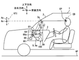
- the head-up display device 100 is mounted on a vehicle 1 and housed in an instrument panel 2.
- vehicle is broadly understood to include vehicles such as aircraft and ships as well as automobiles and railway vehicles.
- the HUD device 100 projects display light of an image onto a windshield 3 as a projection member of the vehicle 1.
- the HUD device 100 displays the image as a virtual image VTI that can be viewed by the occupant. That is, the display light reflected by the windshield 3 reaches the visual recognition area EB in the room of the vehicle 1, and the occupant whose eye point EP for both eyes is located in the visual recognition area EB perceives the light. Then, the occupant can recognize various information displayed as a virtual image VTI.
- the various information displayed as the virtual image VTI includes information related to the operation of the vehicle 1 such as the vehicle speed, the fuel remaining amount, the road information, the visibility auxiliary information and the like.
- the vertical direction of the vehicle 1 (including upper and lower), the longitudinal direction of the vehicle 1 (including forward and backward), and the lateral direction of the vehicle 1 are defined based on the vehicle 1 on the horizontal plane HP.
- the windshield 3 of the vehicle 1 is formed in a plate shape from translucent glass or synthetic resin.
- the windshield 3 forms a projection surface 3a on which the display light is projected in a smooth concave or planar shape.
- the projection surface 3 a faces the lower side of the vehicle 1 and the rear side of the vehicle 1.
- a combiner that is separate from the vehicle 1 may be installed in the vehicle 1 as a projection member, and an image may be projected to the combiner.
- the visual recognition area EB is a space area where the virtual image VTI displayed by the HUD device 100 can be visually recognized at a luminance level satisfying the reference, and is also referred to as an eye box.
- the visual recognition area EB is set to overlap with the eyelids set for the vehicle 1.
- the eyedrops are set based on an eye range that statistically represents the distribution of eye points of the occupant. For details of the eyelids, reference can be made to JIS D 0021: 1998.
- the eyelids are generally set by the vehicle manufacturer according to the position of the seat of the vehicle 1.
- the visual recognition area EB of the present embodiment is designed so that the occupant sitting on the seat can easily visually recognize. More specifically, in the visual recognition area EB, the width in the left-right direction of the vehicle 1 is larger than the width in the vertical direction of the vehicle 1 in consideration that the direction in which both eyes of the occupant are aligned is in the left-right direction It is designed to be.
- the specific configuration of such a HUD device 100 will be described below based on FIGS. 2 to 10.
- the HUD device 100 includes an illumination light source unit 10, a light collecting unit 30, an anisotropic diffusion unit 20, an image display panel 50, a light guide unit 60, and the like, which are accommodated and held in a housing 80. There is.
- the image projection unit 9 is configured around the illumination light source unit 10, the light collecting unit 30, the anisotropic diffusion unit 20, and the image display panel 50.
- Each element 10, 20, 30, 50 provided in the image projection unit 9 is accommodated in a casing 9a having a light shielding property.
- the image projection unit 9 projects display light of an image toward the light guiding unit 60 through the display surface 54 of the image display panel 50.
- the light guide unit 60 guides the display light incident from the image projection unit 9 to the windshield 3.
- the light guide unit 60 has a plane mirror 61 and a concave mirror 63.
- the plane mirror 61 is a reflecting mirror formed by depositing aluminum as the reflecting surface 62 on the surface of a base material made of synthetic resin or glass.
- the reflective surface 62 is formed in a smooth flat shape.
- the display light incident on the plane mirror 61 from the image projection unit 9 is reflected by the reflecting surface 62 toward the concave mirror 63.
- the concave mirror 63 is a reflecting mirror formed by depositing aluminum as the reflecting surface 64 on the surface of a base material made of synthetic resin or glass.
- the reflective surface 64 is formed in a smooth concave shape by curving in a concave shape.
- the display light incident on the concave mirror 63 is reflected by the reflecting surface 64 toward the windshield 3.
- a window 81 is provided in the housing 80 between the concave mirror 63 and the windshield 3.
- a translucent dustproof cover 82 blocks the window 81. Therefore, the display light from the concave mirror 63 passes through the dustproof cover 82 and enters the windshield 3. Thus, the display light reflected by the windshield 3 reaches the viewing area EB, and the occupant can view the virtual image VTI.
- the virtual image VTI is also subjected to the magnifying action by the windshield 3 and an image on the display surface 54 It is visually recognized by the occupant in a more expanded state.
- the image vertical axis Ay is defined in a direction along the vertical direction of the vehicle 1 in the image, and the image right and left in the image perpendicular to the image vertical axis Ay.
- the axis Ax corresponds to the display surface 54 of the image display panel 50
- the short direction SDi of the display surface 54 corresponds to the image vertical axis Ay
- the longitudinal direction LDi of the display surface 54 is the image left and right. It corresponds to the axis Ax. That is, in both the image on the display surface 54 and the image displayed as the virtual image VTI, the dimension in the direction corresponding to the image horizontal axis Ax is longer than the dimension in the direction corresponding to the image vertical axis Ay.
- the HUD device 100 is provided with a drive mechanism 66 that swings and drives the concave mirror 63.
- the drive mechanism 66 drives the stepping motor, for example, in response to the operation of the operation switch by the occupant, and swings the concave mirror 63 around the rotation shaft 66a.
- the rotation axis 66a is arranged to extend along the direction corresponding to the image left and right axis Ax.
- the illumination light source unit 10 is formed by mounting a plurality of light emitting elements 10a on a light source circuit board 12 formed in a flat plate shape.
- the plurality of light emitting elements 10a are arranged at predetermined intervals, for example, in the arrangement direction AD.
- the arrangement direction AD is one direction, but may be arranged in two directions. Further, in the present embodiment, the arrangement direction AD is a direction corresponding to the image horizontal axis Ax.
- Each light emitting element 10a is, for example, a light emitting diode element that generates less heat.
- Each light emitting element 10 a is electrically connected to a power supply through a wiring pattern on the light source circuit board 12. More specifically, each light emitting element 10a is formed by sealing a chip-like blue light emitting diode element with a yellow fluorescent material in which a yellow fluorescent agent is mixed with a translucent synthetic resin. The yellow phosphor is excited to emit yellow light by blue light emitted from the blue light emitting diode element according to the amount of current, and pseudo white and randomly polarized light are emitted from each light emitting element 10a by mixing blue light and yellow light. Illumination light is emitted.
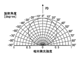
- each light emitting element 10 a emits illumination light with a radiation angle distribution in which the light emission intensity relatively decreases as it deviates from the peak direction PD where the light emission intensity is maximum.
- the light collecting unit 30 is disposed on the light path between the illumination light source unit 10 and the anisotropic diffusion unit 20, and includes a light collecting lens array 31 and a compound lens array 40.
- the condensing unit 30 condenses the illumination light from each of the light emitting elements 10a by the two lens arrays 31 and 40, and emits the collimated illumination light toward the anisotropic diffusion unit 20 and the image display panel 50 on the light path.
- “parallelization” in the present embodiment means that the illumination light is in a state closer to the parallel luminous flux than the state emitted radially from the light emitting element 10 a, and the illumination light is completely collimated luminous flux There is no need.
- the condenser lens array 31 is disposed closer to the illumination light source unit 10 than the complex lens array 40 in the condenser unit 30 on the optical path between the illumination light source unit 10 and the anisotropic diffusion unit 20, in particular, on the optical path.
- the condenser lens array 31 is a lens array formed of a translucent synthetic resin or glass.
- the incident side surface 32 opposed to each light emitting element 10 a has a smooth flat shape common to the entire condenser lens array 31.
- a plurality of focusing convex surfaces 36 are formed in an array on the emission side surface 34 facing the complex lens array 40 in the focusing lens array 31.
- Each condensing convex surface 36 is individually provided so as to form a pair with each light emitting element 10 a.
- the light collecting convex surfaces 36 are provided in the same number as the light emitting elements 10 a in accordance with the number of the light emitting elements 10 a, and are arranged mutually in accordance with the same arrangement direction AD as the light emitting elements 10 a.
- Each condensing convex surface 36 is formed in a smooth curved surface shape which is convexly curved so as to be convex toward the compound lens array 40 side.
- the respective convex convex surfaces 36 are formed in the same spherical shape.
- the shape of each condensing convex surface 36 can be suitably changed according to the shape of the compound lens array 40, for example.
- each light emitting element 10 a is mainly incident on each pair of focusing convex surfaces 36 and is refracted, so that each focusing convex surface 36 receives an individual focusing action.
- the illumination light emitted from the condensing lens array 31 enters the complex lens array 40 while the individual condensing action is extended.
- the complex lens array 40 is located on the light path between the illumination light source unit 10 and the anisotropic diffusion unit 20, in particular, on the side of the anisotropic diffusion unit 20 with respect to the light collection lens array 31 in the light collection unit 30 Is an optical device located at
- the complex lens array 40 is formed of a translucent synthetic resin or glass, and has a generally flat plate shape disposed vertically to the optical axis OA as a whole.
- the optical axis OA is defined as a path of a reference light beam passing through the center of the display surface 54 of the image display panel 50 in the peak direction PD.
- the complex lens array 40 shown in detail in FIGS. 4 and 5 is a lens array in which a plurality of cell blocks 40a are arranged mutually and integrally formed.
- the cell blocks 40a are provided in the same number as the light emitting elements and the light collecting convex surfaces 36, and are arranged in the same arrangement direction AD as the light emitting elements 10a and the light collecting convex surfaces 36.
- the cell blocks 40a have substantially the same shape.
- a plurality of divided lens surfaces 43 are formed in a state of being divided into stripes.
- the dividing direction of the divided lens surface 43 on the incident side surface 42 is, for example, along the arrangement orthogonal direction ND orthogonal to the arrangement direction AD, and the boundary line of the adjacent divided lens surfaces 43 is linear along the arrangement direction AD. It is stretched. Therefore, in the cross section including the arrangement direction AD, one divided lens surface 43 is formed across the plurality of cell blocks 40a. In this way, each divided lens surface 43 is formed as one divided region divided by a predetermined division width Wn.
- a divided convex surface 43 a divided in a convex Fresnel lens shape is provided as the divided lens surface 43.
- the divided convex surface 43 a is formed based on one virtual convex curved surface Sva defined as a virtual lens surface in the complex lens array 40.
- the virtual convex curved surface Sva has a smooth cylindrical surface shape by being curved in the arrangement orthogonal direction ND in a convex shape that is convex toward the condenser lens array 31 side. Therefore, the incident side surface 42 exerts a condensing effect on the illumination light to condense the illumination light mainly in the arrangement orthogonal direction ND.
- each divided lens surface 45 is formed as one divided region divided into regions by a predetermined divided width Wa.
- the approximate plane 45 a is formed based on a virtual convex curved surface Svb defined as a virtual lens surface in the complex lens array 40.
- the virtual convex curved surface Svb has a smooth cylindrical surface shape by being curved in the arrangement direction AD in a convex shape that is convex toward the anisotropic diffusion portion 20 side.
- the approximate plane 45a is formed in a plane as an approximate plane obtained by linear interpolation of a plurality of coordinates extracted from the virtual convex curved surface Svb.
- the end coordinates Ce of the virtual convex curved surface at the end of each divided area are adopted as the plurality of coordinates, and the gradient of the approximate plane 45a is obtained by linear interpolation between the end coordinates Ce. It is prescribed.
- the virtually convex curved surface Svb appears partially on the emission side surface 44 in a state of being made planar by approximation.
- the retrorefractive plane 45 b is disposed between the approximate planes 45 a.
- the retrorefractive plane 45 b is formed based on a virtual inclined surface Ssb defined as a virtual lens surface in the complex lens array 40.
- the virtual inclined surface Ssb is configured by a plurality of planar slopes Ssp replacing the reverse gradient at a location corresponding to the surface vertex of the virtual convex curved surface Svb in the cross section including the arrangement direction AD.
- the gradient of each planar slope Ssp is set to be the gradient in the opposite direction to the gradient of the corresponding portion of the virtual convex curved surface Svb.
- each reference numeral is attached only to a part of the corresponding element.
- the emission side surface 44 exerts a condensing effect on the illumination light, which condenses the illumination light mainly in the arrangement direction AD. More specifically, the illumination light refracted at the approximate plane 45 a receives a refracting action in the same direction as the light condensing action of the normal convex surface as a refracting action, and the deflection amount approximates the slope of the virtual convex curved surface Svb Based on things. For this reason, the virtual light collecting action extends to the illumination light refracted at the approximate plane 45a. The illumination light refracted at the retrorefractive plane 45b is refracted in the opposite direction to the adjacent approximate plane 45a as a refracting action.
- the illumination light reversely refracted in the reverse refraction plane 45b is mixed with the illumination light virtually condensed in the approximate plane 45a.
- the illumination unevenness due to the arrangement of the plurality of light emitting elements 10 a is substantially eliminated, and the collimated illumination light enters the anisotropic diffusion portion 20.
- the anisotropic diffusion unit 20 is a composite light path on the light path between the illumination light source unit 10 and the image display panel 50, particularly on the light path between the focusing unit 30 and the image display panel 50.
- the lens array 40 is arranged to be inclined with respect to the optical axis OA so as to form an inclination angle ⁇ d of, for example, 10 to 15 degrees.
- the anisotropic diffusion unit 20 diffuses the illumination light at an anisotropic diffusion angle.
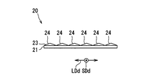
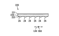
- the anisotropic diffusion portion 20 has a rectangular shape and a substantially flat shape substantially equal to the shape and size of the image display panel 50.
- the short direction SDd of the anisotropic diffusion portion 20 corresponds to the image vertical axis Ay
- the longitudinal direction LDd of the anisotropic diffusion portion 20 corresponds to the image horizontal axis Ax. ing.
- the anisotropic diffusion portion 20 of the present embodiment is formed by laminating an isotropic diffusion layer 21 and an anisotropic prism array layer 23.
- the isotropic diffusion layer 21 and the anisotropic prism array layer 23 are bonded to each other to form illumination light between the isotropic diffusion layer 21 and the anisotropic prism array layer 23. The reflection can be reduced.
- the isotropic diffusion layer 21 is stacked on the anisotropic prism array layer 23 and has an isotropic diffusion angle.
- the isotropic diffusion layer 21 is formed in a sheet shape or a flat plate shape by mixing diffusion particles such as microbeads with a base material made of a translucent synthetic resin having high transmittance such as acrylic resin or polycarbonate resin, for example. ing.
- the diffusion angle of the isotropic diffusion layer 21 of the present embodiment is set to be substantially equal in each direction, for example, about 5 to 25 degrees.
- the diffusion angle in the present embodiment means that the light intensity is half or more with respect to the light intensity at the peak angle at which the light intensity shows the maximum value in the radiation angle distribution of the light after the parallel light flux passes through the diffusion target. Indicates the angle of the range.
- the isotropic diffusion layer 21 exhibits high isotropy with respect to the diffusion of light vertically incident on the isotropic diffusion layer 21, illumination from the complex lens array 40 is performed by the above-described inclined arrangement.
- the isotropy is slightly reduced.
- the inclination angle ⁇ d of the isotropic diffusion layer 21 is 10 to 15 degrees sufficiently smaller than 45 degrees, the diffusion angle of the isotropic diffusion layer 21 is substantially isotropic. It can be regarded as
- the anisotropic prism array layer 23 is stacked on the isotropic diffusion layer 21.
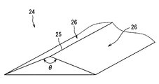
- the anisotropic prism array layer 23 has a plurality of prism elements 24 extending along the short direction SDd corresponding to the image vertical axis Ay.
- the plurality of prism elements 24 are arranged along the longitudinal direction LDd corresponding to the image horizontal axis Ax, whereby the anisotropic prism array layer 23 is formed in a sheet shape.
- the arrangement pitch of the prism elements 24 is preferably set in the range of several micrometers to several hundreds of micrometers. Although each prism element 24 is schematically illustrated in a large size in FIG. 6, a larger number of prism elements 24 are actually arranged.
- Each prism element 24 of the present embodiment extends along a lateral direction SDd corresponding to the image vertical axis Ay, with a triangular cross section in the longitudinal direction LDd corresponding to the image horizontal axis Ax. doing.
- Each prism element 24 has a triangular prism shape in which a pair of planar refracting surfaces 26 is formed by sandwiching the apex 25 pointed on the opposite side to the isotropic diffusion layer 21 in the triangular cross section.
- the apex angle ⁇ at the top 25 of each prism element 24 is equal to one another between the prism elements 24.
- the apex angle ⁇ is an obtuse angle, and more preferably in the range of 120 to 160 degrees.
- the top portion 25 of the anisotropic prism array layer 23 is disposed so as to face the illumination light source unit 10 and the light collecting unit 30 on the optical path.
- the anisotropic prism array layer 23 is disposed closer to the illumination light source unit 10 and the light collecting unit 30 than the isotropic diffusion layer 21, and the isotropic diffusion layer 21 is closer to the anisotropic prism array layer 23.
- each refractive surface 26 of the anisotropic prism array layer 23 When illumination light from the compound lens array 40 is incident on such an anisotropic diffusion portion 20, first, the illumination light is refracted at each refractive surface 26 of the anisotropic prism array layer 23.
- the illumination light is deflected in the longitudinal direction LDd by refraction because each refracting surface 26 is inclined so as to approach the isotropic diffusion layer 21 as the distance from the top 25 along the longitudinal direction LDd increases. It becomes. Since the directions of inclination of the pair of refracting surfaces 26 are opposite to each other, the directions of deflection are also reversed according to the refracting surfaces 26 that have entered. Thus, the illumination light deflected in the longitudinal direction LDd enters the isotropic diffusion layer 21.
- the illumination light is the isotropic diffusion layer 21.
- the isotropic diffusion layer 21 itself defines the diffusion performance with an isotropic diffusion angle as described above, the diffusion of illumination light after being diffused to the actual isotropic diffusion layer 21
- the corners are different between the short direction SDd and the longitudinal direction LDd.
- the diffusion angle in the longitudinal direction LDd corresponding to the image horizontal axis Ax becomes larger than the diffusion angle in the lateral direction SDd corresponding to the image vertical axis Ay.
- illumination light diffused at different diffusion angles in each direction LDd and SDd is incident on the image display panel 50 by the anisotropic diffusion unit 20.
- the image display panel 50 of the present embodiment is a liquid crystal panel using thin film transistors (TFTs), and is an active matrix type and transmission type formed of, for example, a plurality of liquid crystal pixels 50 a arranged in a two-dimensional manner. It is a liquid crystal panel.
- TFTs thin film transistors
- the image display panel 50 has a rectangular panel shape with the image horizontal axis Ax as the longitudinal direction LDi.
- the longitudinal direction LDi is along the arrangement direction AD.
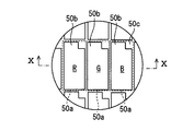
- the liquid crystal pixels 50a shown in FIG. 9 are two-dimensionally arranged in the longitudinal direction LDi and the lateral direction SDi, and the display surface 54 for emitting an image as display light on the light guide 60 side is also rectangular as described above. It has a shape.
- a transmissive portion 50b is provided so as to penetrate in the normal direction of the display surface 54, and a wiring portion 50c formed so as to surround the transmissive portion 50b.
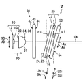
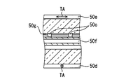
- the image display panel 50 is formed by laminating a liquid crystal layer 50f and the like sandwiched between a pair of polarizing plates 50d and 50e and a pair of polarizing plates 50d and 50e. It is presenting.
- Each of the polarizing plates 50d and 50e has a property of transmitting light polarized in the direction along the transmission axis TA and absorbing light polarized in the direction perpendicular to the transmission axis TA.
- 50e are disposed with the transmission axes TA orthogonal to each other.
- the liquid crystal layer 50 f can rotate the polarization direction of light incident on the liquid crystal layer 50 f according to the applied voltage by voltage application for each liquid crystal pixel 50 a. By the rotation of the polarization direction, it is possible to change the ratio of light transmitted through the polarizing plate 50e on the emission side, that is, the transmittance.
- the image display panel 50 controls the transmittance of each liquid crystal pixel 50 a with respect to the incidence of the illumination light on the illumination target surface 52 which is the surface on the anisotropic diffusion portion 20 side. That is, the image display panel 50 functions as an image forming unit that forms an image by partial transmission of illumination light and emits it as display light. Adjacent liquid crystal pixels 50a are provided with color filters 50g of different colors (for example, red, green and blue), and by combining these, various colors are realized as display colors .
- the image display panel 50 has its illumination target surface 52 opposed to the isotropic diffusion layer 21 of the anisotropic diffusion portion 20 with a slight gap therebetween, It is disposed in parallel with the diffusion unit 20. That is, the image display panel 50 is also disposed inclined with respect to the optical axis OA so as to form an inclination angle ⁇ i of, for example, 10 to 15 degrees with respect to the complex lens array.
- the distance between the anisotropic diffusion unit 20 and the image display panel 50 is set to be smaller than the distance between the anisotropic diffusion unit 20 and the complex lens array 40.
- the illumination light incident on the illumination target surface 52 of the image display panel 50 from the anisotropic diffusion unit 20 passes through the transmission unit 50b of each liquid crystal pixel 50a as described above, and is emitted as display light from the transmission unit 50b. Ru. At the time of emission, the display light is oriented based on the anisotropic diffusion angle in each anisotropic diffusion portion from each liquid crystal pixel 50a.
- the diffusion angle in the longitudinal direction LDd is set to be larger than the diffusion angle in the lateral direction SDd, so the display light emitted from each liquid crystal pixel 50a also corresponds to the image horizontal axis Ax.
- the orientation angle is larger than the transverse direction SDi corresponding to the image vertical axis Ay.
- the range to be reached characterizes the shape and the size of the visual recognition area EB. That is, according to the orientation of the display light described above, in the viewing area EB, the size in the left-right direction of the vehicle 1 corresponding to the image horizontal axis Ax is larger than the size in the vertical direction of the vehicle 1 corresponding to the image vertical axis Ay Become.
- the visual recognition area EB can sufficiently cover the eye points EP of both eyes of the occupants aligned in the left and right direction of the vehicle 1, and high visual recognition of the virtual image VTI is realized with both eyes.
- each of the image display panel 50 and the anisotropic diffusion portion 20 is along the image left-right axis Ax (that is, along the longitudinal direction LDi or LDd) from the posture perpendicular to the optical axis OA.
- the inclination direction is set by being inclined and disposed in a state of being rotated about a virtual rotation axis.
- the virtual image VTI visually recognized from the visual recognition area EB is inclined and visually recognized, and at the same time, sunlight etc. which enters the HUD device 100 through the windshield 3 It is possible to suppress the situation in which the outside light is reflected by the display surface 54 and reaches the viewing area EB.
- the anisotropic prism array layer 23 of the anisotropic diffusion unit 20 has a short side corresponding to the image vertical axis Ay. Since the prism elements 24 extending in the direction SDd are arrayed, they hardly exert optical effects such as refraction with respect to the longitudinal direction LDd corresponding to the image vertical axis Ay. That is, the anisotropic diffusion portion 20 of the present embodiment has small inclination angle dependency around the rotation axis along the image horizontal axis Ax, and has high versatility with respect to the change of the inclination angle ⁇ d.
- the anisotropic diffusion portion 20 is changed. There is less need to change the internal design of itself.
- the diffusion unit 20 disposed on the light path between the illumination light source unit 10 and the image display panel 50 as the image forming unit diffuses the illumination light at an anisotropic diffusion angle.
- the anisotropic diffusion unit 20 the diffusion angle in the longitudinal direction LDd corresponding to the image horizontal axis Ax is larger than the diffusion angle in the lateral direction SDd corresponding to the image vertical axis Ay. Therefore, the display light transmitted through the image display panel 50 and emitted and reflected by the windshield 3 as the projection member is spread in a direction perpendicular to the vertical direction of the vehicle 1 more than the vertical direction of the vehicle 1 to view the visual field EB To reach.
- the visual recognition area EB is expanded in a direction perpendicular to the vertical direction of the vehicle 1 in which both eyes of the occupant are aligned, so that the visibility of the virtual image VTI with both eyes of the occupant is improved.
- diffusion is suppressed more than in the direction perpendicular to the vertical direction of the vehicle 1, so the brightness of the visually recognized virtual image VTI is improved accordingly can do.
- the anisotropic diffusion portion 20 is an anisotropic prism array in which the anisotropic diffusion layer 21 is stacked on the isotropic diffusion layer 21 having an isotropic diffusion angle and the isotropic diffusion layer 21. And a layer 23.
- the anisotropic prism array layer 23 extends along the longitudinal direction LDd corresponding to the image vertical axis Ay, and deflects the illumination light in the lateral direction SDd corresponding to the image vertical axis Ay Because they are formed along the longitudinal direction LDd corresponding to the axis Ax, the isotropic diffusion in the isotropic diffusion layer 21 is converted into anisotropic diffusion, so that anisotropic The diffusion angle can be easily realized.
- each prism element 24 extends along the short direction SDd corresponding to the image vertical axis Ay with a triangular cross section, and points on the opposite side to the isotropic diffusion layer 21 in the triangular cross section.
- the top portion 25 By sandwiching the top portion 25, it has a triangular prism shape in which a pair of refractive surfaces 26 for refracting illumination light is formed.
- Such a pair of refracting surfaces 26 mixes illumination light deflected in opposite directions in the longitudinal direction LDd corresponding to the image horizontal axis Ax, so that diffusion in the longitudinal direction LDd corresponding to the image horizontal axis Ax is performed.
- the corners can be made large reliably. Therefore, the visual recognition area EB is expanded in a direction perpendicular to the vertical direction of the vehicle 1 in which the occupants' eyes are aligned, and the visibility of the virtual image VTI with both eyes can be reliably improved.
- the apex angle ⁇ at the top 25 is an obtuse angle.
- the illumination light is reflected by the refracting surface 26 and the illumination light is deviated from the optical path, etc., so that the situation in which the quality or the brightness of the virtual image VTI is lowered can be suppressed. And illumination light can be diffused efficiently. Therefore, the visibility of the virtual image VTI can be enhanced.
- the top portion 25 of the anisotropic prism array layer 23 is disposed so as to face the illumination light source unit 10 on the optical path.
- the anisotropic prism array layer 23 does not face the image display panel 50, so that even if vibration or the like of the vehicle 1 occurs, the top 25 is rubbed against the image display panel 50 to avoid wear or breakage. can do. Therefore, the visibility of the virtual image VTI can be maintained for a long time.
- the anisotropic diffusion portion 20 is disposed to be inclined with respect to the optical axis OA so as to face the image and to be parallel to the image display panel 50. In this way, the size of the anisotropic diffusion portion 20 itself can be suppressed, and the distance until the illumination light diffused by the anisotropic diffusion portion 20 enters the image display panel 50 is the entire distance.
- the quality of the virtual image VTI can be homogenized in each area of the image, as it is substantially constant over the area.
- the second embodiment is a modification of the first embodiment.
- the second embodiment will be described focusing on differences from the first embodiment.
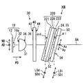
- the anisotropic diffusion portion 220 of the second embodiment further includes a polarizing element layer 228.
- the polarizing element layer 228 is laminated on the isotropic diffusion layer 221 and the anisotropic prism array layer 223 so as to regulate transmission of predetermined polarized light.
- the polarization element layer 228 of the present embodiment is a reflection type deflection element using a wire grid.
- the polarizing element layer 228 is formed in a film shape, and includes a plurality of metal wires extending in the direction orthogonal to the transmission axis TA of the polarizing plate 50 d on the incident side of the image display panel 50.
- the plurality of metal wires are made of, for example, aluminum or the like and are arranged in parallel with each other at a predetermined pitch.
- the predetermined pitch is set to be smaller than most wavelengths of the illumination light, and is set to, for example, about 100 to 200 ⁇ m.
- the polarizing element layer 228 reflects light polarized in the extending direction of the metal wire and transmits light polarized in a direction perpendicular to the extending direction.
- an isotropic diffusion layer 221, a polarizing element layer 228, and an anisotropic prism array layer 223 are stacked in order from the illumination light source unit 10 side. For this reason, illumination light which enters the anisotropic diffusion portion 220 from the complex lens array 40 is first diffused isotropically in the isotropic diffusion layer 221. Thereafter, of the illumination light, only the polarized light along the transmission axis TA of the polarizing plate 50 d on the incident side of the image display panel 50 transmits the polarizing element layer 228.
- the polarization element layer 228 regulates transmission of the anisotropic diffusion portion 220 for polarization that can be absorbed by the polarization plate 50d.
- the polarized illumination light is deflected by the pair of refracting surfaces 26 of the anisotropic prism array layer 223 in the longitudinal direction LDd corresponding to the image horizontal axis Ax.
- the anisotropic diffusion unit 220 changes the illumination light in a state in which the diffusion angle of the longitudinal direction LDd corresponding to the image horizontal axis Ax is larger than the diffusion angle of the lateral direction SDd corresponding to the image vertical axis Ay. It will spread more In the first embodiment, the illumination light diffused by the anisotropic diffusion unit 20 is randomly polarized light, but the anisotropic diffusion unit 220 of the second embodiment is a polarized light on the incident side of the image display panel 50. The difference is that the linearly polarized light along the transmission axis TA of the plate 50d is diffused.
- the polarization element layer 228 is made to transmit after the diffusion in the isotropic diffusion layer 221.
- the degree of polarization of the illumination light emitted from the directional diffusion unit 220 is increased.
- the metal wire stretching direction follows the short direction SDd corresponding to the image vertical axis Ay Become.
- the illumination light is incident on the pair of refracting surfaces 26 of the anisotropic prism array layer 223 as p-polarized light, reflection of the illumination light at the refracting surface 26 is suppressed.
- the anisotropic diffusion portion 220 is stacked on the isotropic diffusion layer 221 and the anisotropic prism array layer 223, and the polarizer 50d on the anisotropic diffusion portion 220 side is used.
- a polarization element layer 228 which regulates the transmission of the anisotropic diffusion portion 220 with respect to the polarized light to be absorbed.
- the anisotropic diffusion unit 220 in the anisotropic diffusion unit 220, the isotropic diffusion layer 221, the polarization element layer 228, and the anisotropic prism array layer 223 are sequentially stacked from the illumination light source unit 10 side. .
- the degree of polarization of the illumination light emitted from the anisotropic diffusion portion 220 is increased, so that the polarization plate 50d of the image display panel 50 absorbs the light. It is possible to further reduce the proportion of light emitted. As a result, the effect of suppressing the temperature rise of the image display panel 50 can be enhanced.
- the top portion 25 of the anisotropic prism array layer 23 may be disposed facing the image display panel 50 on the optical path.
- the anisotropic prism array layer 23 is disposed closer to the image display panel 50 than the isotropic diffusion layer 21, and the isotropic diffusion layer 21 is closer to the illumination light source unit 10 than the anisotropic prism array layer 23. You may arrange
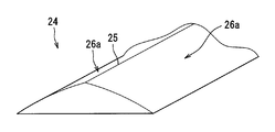
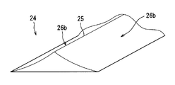
- the prism elements 24 of the anisotropic prism array layer 23 have a structure in which the pair of refractive surfaces 26a sandwiching the top 25 have a convexly curved cylindrical surface shape shown in FIG. It is possible to employ a structure or the like in which the refracting surface 26b of this is a cylindrical surface that curves in a concave shape shown in FIG.
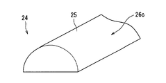
- the prism element 24 may adopt a semicircular cross-sectional structure (that is, a structure in which a single cylindrical refracting surface 26 c is provided) in which the top 25 is not sharp. it can.
- the isotropic diffusion layer 21 may be realized by having the property.
- a reflective polarizing element using a wire grid not only a reflective polarizing element using a wire grid but also a reflective polarizing element such as DBEF (registered trademark) manufactured by 3M Co., Ltd. is used for the polarizing element layer 228.
- DBEF registered trademark
- an absorptive polarizing element can be employed for the polarizing element layer 2228.
- a gap may be provided between the isotropic diffusion layer 21 and the anisotropic prism array layer 23.
- the anisotropic diffusion unit 20 may be disposed to be bonded to the illumination target surface 52 of the image display panel 50.
- the anisotropic diffusion portion 20 may be disposed to be inclined with respect to the image display panel 50 by being disposed perpendicularly to the optical axis OA. Further, the anisotropic diffusion portion 20 and the image display panel 50 may be disposed in parallel with each other by being disposed perpendicularly to the optical axis OA.
- the compound lens array 40 may be disposed in parallel with the anisotropic diffusion portion 20 by being disposed to be inclined with respect to the optical axis OA.
Landscapes
- Physics & Mathematics (AREA)
- General Physics & Mathematics (AREA)
- Optics & Photonics (AREA)
- Engineering & Computer Science (AREA)
- Chemical & Material Sciences (AREA)
- Combustion & Propulsion (AREA)
- Transportation (AREA)
- Mechanical Engineering (AREA)
- Instrument Panels (AREA)
Priority Applications (3)
| Application Number | Priority Date | Filing Date | Title |
|---|---|---|---|
| DE112018004945.0T DE112018004945B4 (de) | 2017-09-07 | 2018-07-12 | Head-up-display-vorrichtung und bildprojektionseinheit |
| CN201880057359.9A CN111051960A (zh) | 2017-09-07 | 2018-07-12 | 平视显示器装置以及图像投射单元 |
| US16/787,908 US11385462B2 (en) | 2017-09-07 | 2020-02-11 | Head-up display device and image projection unit |
Applications Claiming Priority (2)
| Application Number | Priority Date | Filing Date | Title |
|---|---|---|---|
| JP2017-172396 | 2017-09-07 | ||
| JP2017172396A JP6711337B2 (ja) | 2017-09-07 | 2017-09-07 | ヘッドアップディスプレイ装置及び画像投射ユニット |
Related Child Applications (1)
| Application Number | Title | Priority Date | Filing Date |
|---|---|---|---|
| US16/787,908 Continuation US11385462B2 (en) | 2017-09-07 | 2020-02-11 | Head-up display device and image projection unit |
Publications (1)
| Publication Number | Publication Date |
|---|---|
| WO2019049509A1 true WO2019049509A1 (ja) | 2019-03-14 |
Family
ID=65633801
Family Applications (1)
| Application Number | Title | Priority Date | Filing Date |
|---|---|---|---|
| PCT/JP2018/026356 Ceased WO2019049509A1 (ja) | 2017-09-07 | 2018-07-12 | ヘッドアップディスプレイ装置及び画像投射ユニット |
Country Status (5)
| Country | Link |
|---|---|
| US (1) | US11385462B2 (enExample) |
| JP (1) | JP6711337B2 (enExample) |
| CN (1) | CN111051960A (enExample) |
| DE (1) | DE112018004945B4 (enExample) |
| WO (1) | WO2019049509A1 (enExample) |
Cited By (1)
| Publication number | Priority date | Publication date | Assignee | Title |
|---|---|---|---|---|
| CN111948814A (zh) * | 2019-05-17 | 2020-11-17 | 未来(北京)黑科技有限公司 | 一种抬头显示系统 |
Families Citing this family (12)
| Publication number | Priority date | Publication date | Assignee | Title |
|---|---|---|---|---|
| DE112019002950T5 (de) * | 2018-07-11 | 2021-04-08 | Nippon Seiki Co. Ltd. | Anzeigevorrichtung und Head-up-Display-Vorrichtung |
| JP7172840B2 (ja) | 2019-05-07 | 2022-11-16 | 株式会社デンソー | 虚像表示装置 |
| WO2021085447A1 (ja) * | 2019-10-31 | 2021-05-06 | 日本精機株式会社 | ヘッドアップディスプレイ装置 |
| JP7497201B2 (ja) * | 2020-04-24 | 2024-06-10 | 株式会社小糸製作所 | 車両用表示装置 |
| JP7342790B2 (ja) * | 2020-05-28 | 2023-09-12 | 株式会社デンソー | 虚像表示装置 |
| EP4163713A4 (en) * | 2020-06-04 | 2023-12-06 | Panasonic Intellectual Property Management Co., Ltd. | DISPLAY DEVICE, HEAD-UP DISPLAY AND MOBILE OBJECT |
| JP7318604B2 (ja) * | 2020-07-16 | 2023-08-01 | 株式会社デンソー | 虚像表示装置 |
| JP2022021975A (ja) * | 2020-07-23 | 2022-02-03 | 株式会社デンソー | ヘッドアップディスプレイ装置及びヘッドアップディスプレイ用拡散板 |
| JP2022188796A (ja) * | 2021-06-10 | 2022-12-22 | 日本精機株式会社 | ヘッドアップディスプレイ |
| DE102021128517A1 (de) * | 2021-11-02 | 2023-05-04 | Bayerische Motoren Werke Aktiengesellschaft | Kopf-Oben-Anzeige, Fortbewegungsmittel und Anordnung für eine Kopf-Oben-Anzeige |
| JP2023174345A (ja) * | 2022-05-27 | 2023-12-07 | パナソニックIpマネジメント株式会社 | 表示装置、およびヘッドアップディスプレイ |
| JP2024090393A (ja) * | 2022-12-23 | 2024-07-04 | 日本精機株式会社 | ヘッドアップディスプレイ装置及び乗り物 |
Citations (6)
| Publication number | Priority date | Publication date | Assignee | Title |
|---|---|---|---|---|
| JPH08190074A (ja) * | 1994-09-30 | 1996-07-23 | Hughes Aircraft Co | ヘッドアップディスプレイ用の高強度画像投影ソース |
| JP2015148664A (ja) * | 2014-02-05 | 2015-08-20 | 株式会社リコー | 画像表示装置及び移動体 |
| JP2016071300A (ja) * | 2014-10-02 | 2016-05-09 | 大日本印刷株式会社 | 透過型スクリーン及びそれを用いたヘッドアップディスプレイ装置 |
| JP2017009864A (ja) * | 2015-06-24 | 2017-01-12 | 日本精機株式会社 | 液晶表示装置 |
| JP2017107768A (ja) * | 2015-12-10 | 2017-06-15 | ミネベアミツミ株式会社 | 面状照明装置、及びそれを備える光学機器 |
| JP2017146424A (ja) * | 2016-02-16 | 2017-08-24 | 株式会社デンソー | ヘッドアップディスプレイ装置 |
Family Cites Families (15)
| Publication number | Priority date | Publication date | Assignee | Title |
|---|---|---|---|---|
| DE19920789A1 (de) * | 1998-11-02 | 2000-05-04 | Mannesmann Vdo Ag | Zur Verwendung in einem Kraftfahrzeug vorgesehene Anzeigeeinheit |
| JP4099964B2 (ja) * | 2000-09-29 | 2008-06-11 | 株式会社日立製作所 | 背面投写型ディスプレイ装置及びそれに用いられる透過型スクリーン |
| JP2005010545A (ja) * | 2003-06-20 | 2005-01-13 | Hitachi Ltd | 透過型スクリーン及びそれを用いた背面投写型映像表示装置 |
| JP2005037496A (ja) * | 2003-07-16 | 2005-02-10 | Dainippon Printing Co Ltd | 透過型スクリーン及び拡散シート |
| GB2405519A (en) * | 2003-08-30 | 2005-03-02 | Sharp Kk | A multiple-view directional display |
| CN100451800C (zh) * | 2004-10-25 | 2009-01-14 | 皇家飞利浦电子股份有限公司 | 显示装置 |
| JP2007086379A (ja) * | 2005-09-21 | 2007-04-05 | Fujitsu Ten Ltd | 車載用液晶表示装置 |
| JP4671117B2 (ja) | 2005-09-22 | 2011-04-13 | ミネベア株式会社 | 照明装置及びそれを用いた光源ユニット |
| JP5055765B2 (ja) * | 2005-12-22 | 2012-10-24 | 株式会社日立製作所 | 画像表示装置、及び、それに用いるフレネルレンズシート並びにスクリーン |
| JP2008179864A (ja) * | 2007-01-25 | 2008-08-07 | Daido Steel Co Ltd | Ni基合金の製造方法 |
| JP5353203B2 (ja) | 2007-12-18 | 2013-11-27 | 日本精機株式会社 | ヘッドアップディスプレイ装置 |
| TWI443438B (zh) * | 2012-05-04 | 2014-07-01 | Young Optics Inc | 投影系統 |
| CN103514856A (zh) * | 2012-06-21 | 2014-01-15 | 鸿富锦精密工业(深圳)有限公司 | 屏幕共享系统及其双视显示器 |
| JP2016139108A (ja) | 2014-04-14 | 2016-08-04 | 王子ホールディングス株式会社 | 非平面形状の表面微細凹凸構造体 |
| JP6459921B2 (ja) * | 2015-11-19 | 2019-01-30 | 株式会社デンソー | ヘッドアップディスプレイ装置 |
-
2017
- 2017-09-07 JP JP2017172396A patent/JP6711337B2/ja active Active
-
2018
- 2018-07-12 DE DE112018004945.0T patent/DE112018004945B4/de not_active Expired - Fee Related
- 2018-07-12 CN CN201880057359.9A patent/CN111051960A/zh active Pending
- 2018-07-12 WO PCT/JP2018/026356 patent/WO2019049509A1/ja not_active Ceased
-
2020
- 2020-02-11 US US16/787,908 patent/US11385462B2/en active Active
Patent Citations (6)
| Publication number | Priority date | Publication date | Assignee | Title |
|---|---|---|---|---|
| JPH08190074A (ja) * | 1994-09-30 | 1996-07-23 | Hughes Aircraft Co | ヘッドアップディスプレイ用の高強度画像投影ソース |
| JP2015148664A (ja) * | 2014-02-05 | 2015-08-20 | 株式会社リコー | 画像表示装置及び移動体 |
| JP2016071300A (ja) * | 2014-10-02 | 2016-05-09 | 大日本印刷株式会社 | 透過型スクリーン及びそれを用いたヘッドアップディスプレイ装置 |
| JP2017009864A (ja) * | 2015-06-24 | 2017-01-12 | 日本精機株式会社 | 液晶表示装置 |
| JP2017107768A (ja) * | 2015-12-10 | 2017-06-15 | ミネベアミツミ株式会社 | 面状照明装置、及びそれを備える光学機器 |
| JP2017146424A (ja) * | 2016-02-16 | 2017-08-24 | 株式会社デンソー | ヘッドアップディスプレイ装置 |
Cited By (1)
| Publication number | Priority date | Publication date | Assignee | Title |
|---|---|---|---|---|
| CN111948814A (zh) * | 2019-05-17 | 2020-11-17 | 未来(北京)黑科技有限公司 | 一种抬头显示系统 |
Also Published As
| Publication number | Publication date |
|---|---|
| JP6711337B2 (ja) | 2020-06-17 |
| DE112018004945B4 (de) | 2024-03-14 |
| CN111051960A (zh) | 2020-04-21 |
| DE112018004945T5 (de) | 2020-07-09 |
| JP2019049581A (ja) | 2019-03-28 |
| US20200174253A1 (en) | 2020-06-04 |
| US11385462B2 (en) | 2022-07-12 |
Similar Documents
| Publication | Publication Date | Title |
|---|---|---|
| US11385462B2 (en) | Head-up display device and image projection unit | |
| JP6508125B2 (ja) | ヘッドアップディスプレイ装置及び画像投射ユニット | |
| JP7195454B2 (ja) | 光源装置、それを利用した情報表示システムおよびヘッドアップディスプレイ装置 | |
| JP6459921B2 (ja) | ヘッドアップディスプレイ装置 | |
| JP6579212B2 (ja) | ヘッドアップディスプレイ装置 | |
| JP7282174B2 (ja) | 情報表示システム | |
| JP6481649B2 (ja) | ヘッドアップディスプレイ装置 | |
| JP7172840B2 (ja) | 虚像表示装置 | |
| KR101940946B1 (ko) | 헤드업 디스플레이 장치 | |
| US20240061240A1 (en) | Air floating video display apparatus and light source | |
| WO2017130481A1 (ja) | ヘッドアップディスプレイ装置及びその生産方法 | |
| WO2020158258A1 (ja) | 虚像表示装置 | |
| US20230113774A1 (en) | Head-up display | |
| JP6982816B2 (ja) | 画像表示装置、虚像表示装置、移動体 | |
| JP7163804B2 (ja) | ヘッドアップディスプレイ用照明ユニット | |
| WO2022019101A1 (ja) | ヘッドアップディスプレイ装置及びヘッドアップディスプレイ用拡散板 | |
| WO2017145558A1 (ja) | ヘッドアップディスプレイ装置 | |
| EP4120001B1 (en) | Virtual image display device | |
| JP2025018569A (ja) | 光源装置とそれを利用した表示装置 | |
| JP4457752B2 (ja) | 液晶表示装置 | |
| JP2024041008A (ja) | 画像投影装置 |
Legal Events
| Date | Code | Title | Description |
|---|---|---|---|
| 121 | Ep: the epo has been informed by wipo that ep was designated in this application |
Ref document number: 18853777 Country of ref document: EP Kind code of ref document: A1 |
|
| 122 | Ep: pct application non-entry in european phase |
Ref document number: 18853777 Country of ref document: EP Kind code of ref document: A1 |