WO2019044457A1 - 画像取得装置およびその制御方法 - Google Patents
画像取得装置およびその制御方法 Download PDFInfo
- Publication number
- WO2019044457A1 WO2019044457A1 PCT/JP2018/030043 JP2018030043W WO2019044457A1 WO 2019044457 A1 WO2019044457 A1 WO 2019044457A1 JP 2018030043 W JP2018030043 W JP 2018030043W WO 2019044457 A1 WO2019044457 A1 WO 2019044457A1
- Authority
- WO
- WIPO (PCT)
- Prior art keywords
- light
- optical path
- path length
- adjustment
- focus
- Prior art date
- Legal status (The legal status is an assumption and is not a legal conclusion. Google has not performed a legal analysis and makes no representation as to the accuracy of the status listed.)
- Ceased
Links
Images


Classifications
-
- G—PHYSICS
- G01—MEASURING; TESTING
- G01B—MEASURING LENGTH, THICKNESS OR SIMILAR LINEAR DIMENSIONS; MEASURING ANGLES; MEASURING AREAS; MEASURING IRREGULARITIES OF SURFACES OR CONTOURS
- G01B9/00—Measuring instruments characterised by the use of optical techniques
- G01B9/02—Interferometers
- G01B9/0209—Low-coherence interferometers
- G01B9/02091—Tomographic interferometers, e.g. based on optical coherence
-
- A—HUMAN NECESSITIES
- A61—MEDICAL OR VETERINARY SCIENCE; HYGIENE
- A61B—DIAGNOSIS; SURGERY; IDENTIFICATION
- A61B3/00—Apparatus for testing the eyes; Instruments for examining the eyes
- A61B3/10—Objective types, i.e. instruments for examining the eyes independent of the patients' perceptions or reactions
- A61B3/102—Objective types, i.e. instruments for examining the eyes independent of the patients' perceptions or reactions for optical coherence tomography [OCT]
-
- A—HUMAN NECESSITIES
- A61—MEDICAL OR VETERINARY SCIENCE; HYGIENE
- A61B—DIAGNOSIS; SURGERY; IDENTIFICATION
- A61B3/00—Apparatus for testing the eyes; Instruments for examining the eyes
- A61B3/10—Objective types, i.e. instruments for examining the eyes independent of the patients' perceptions or reactions
- A61B3/12—Objective types, i.e. instruments for examining the eyes independent of the patients' perceptions or reactions for looking at the eye fundus, e.g. ophthalmoscopes
- A61B3/1225—Objective types, i.e. instruments for examining the eyes independent of the patients' perceptions or reactions for looking at the eye fundus, e.g. ophthalmoscopes using coherent radiation
-
- A—HUMAN NECESSITIES
- A61—MEDICAL OR VETERINARY SCIENCE; HYGIENE
- A61B—DIAGNOSIS; SURGERY; IDENTIFICATION
- A61B3/00—Apparatus for testing the eyes; Instruments for examining the eyes
- A61B3/10—Objective types, i.e. instruments for examining the eyes independent of the patients' perceptions or reactions
- A61B3/14—Arrangements specially adapted for eye photography
-
- G—PHYSICS
- G01—MEASURING; TESTING
- G01B—MEASURING LENGTH, THICKNESS OR SIMILAR LINEAR DIMENSIONS; MEASURING ANGLES; MEASURING AREAS; MEASURING IRREGULARITIES OF SURFACES OR CONTOURS
- G01B9/00—Measuring instruments characterised by the use of optical techniques
- G01B9/02—Interferometers
- G01B9/02015—Interferometers characterised by the beam path configuration
- G01B9/02029—Combination with non-interferometric systems, i.e. for measuring the object
- G01B9/0203—With imaging systems
-
- G—PHYSICS
- G01—MEASURING; TESTING
- G01B—MEASURING LENGTH, THICKNESS OR SIMILAR LINEAR DIMENSIONS; MEASURING ANGLES; MEASURING AREAS; MEASURING IRREGULARITIES OF SURFACES OR CONTOURS
- G01B9/00—Measuring instruments characterised by the use of optical techniques
- G01B9/02—Interferometers
- G01B9/02034—Interferometers characterised by particularly shaped beams or wavefronts
- G01B9/02038—Shaping the wavefront, e.g. generating a spherical wavefront
- G01B9/02039—Shaping the wavefront, e.g. generating a spherical wavefront by matching the wavefront with a particular object surface shape
-
- G—PHYSICS
- G01—MEASURING; TESTING
- G01B—MEASURING LENGTH, THICKNESS OR SIMILAR LINEAR DIMENSIONS; MEASURING ANGLES; MEASURING AREAS; MEASURING IRREGULARITIES OF SURFACES OR CONTOURS
- G01B9/00—Measuring instruments characterised by the use of optical techniques
- G01B9/02—Interferometers
- G01B9/02055—Reduction or prevention of errors; Testing; Calibration
- G01B9/02062—Active error reduction, i.e. varying with time
- G01B9/02063—Active error reduction, i.e. varying with time by particular alignment of focus position, e.g. dynamic focussing in optical coherence tomography
-
- G—PHYSICS
- G01—MEASURING; TESTING
- G01B—MEASURING LENGTH, THICKNESS OR SIMILAR LINEAR DIMENSIONS; MEASURING ANGLES; MEASURING AREAS; MEASURING IRREGULARITIES OF SURFACES OR CONTOURS
- G01B9/00—Measuring instruments characterised by the use of optical techniques
- G01B9/02—Interferometers
- G01B9/02055—Reduction or prevention of errors; Testing; Calibration
- G01B9/02062—Active error reduction, i.e. varying with time
- G01B9/02067—Active error reduction, i.e. varying with time by electronic control systems, i.e. using feedback acting on optics or light
-
- G—PHYSICS
- G01—MEASURING; TESTING
- G01N—INVESTIGATING OR ANALYSING MATERIALS BY DETERMINING THEIR CHEMICAL OR PHYSICAL PROPERTIES
- G01N21/00—Investigating or analysing materials by the use of optical means, i.e. using sub-millimetre waves, infrared, visible or ultraviolet light
- G01N21/17—Systems in which incident light is modified in accordance with the properties of the material investigated
-
- A—HUMAN NECESSITIES
- A61—MEDICAL OR VETERINARY SCIENCE; HYGIENE
- A61B—DIAGNOSIS; SURGERY; IDENTIFICATION
- A61B3/00—Apparatus for testing the eyes; Instruments for examining the eyes
- A61B3/10—Objective types, i.e. instruments for examining the eyes independent of the patients' perceptions or reactions
- A61B3/14—Arrangements specially adapted for eye photography
- A61B3/15—Arrangements specially adapted for eye photography with means for aligning, spacing or blocking spurious reflection ; with means for relaxing
- A61B3/152—Arrangements specially adapted for eye photography with means for aligning, spacing or blocking spurious reflection ; with means for relaxing for aligning
Definitions
- the present invention relates to an image acquisition apparatus and a control method therefor, and more particularly to an image acquisition apparatus used for acquiring a tomographic image of a fundus of an eye to be examined and a control method therefor.
- OCT Optical Coherence Tomography
- OCT apparatus an apparatus for capturing a tomographic image by such OCT will be referred to as an OCT apparatus.
- an adaptive optics OCT system has been developed that has an adaptive optics system that measures the aberration of the subject's eye in real time using a wavefront sensor and corrects the aberration generated in the subject's eye with a wavefront correction device. It is possible to acquire lateral resolution tomographic images.
- the reduction in aberration measurement accuracy due to the unnecessary reflected light from the lens surface or the like entering the wavefront sensor becomes a problem.
- a reflection optical system mainly composed of a mirror is used.
- focus adjustment on the fundus of an eye to be examined is performed by moving a focusing optical system configured by a mirror disposed in a measurement light path.
- the optical path length of the measurement light also changes with the focus adjustment. Since the display position in the depth direction of the tomographic image depends on the optical path length difference between the measurement light and the reference light, when the optical path length of the measurement light changes, the display position of the tomographic image also changes. Adjustment of the display position of the tomographic image can be performed by adjusting the optical path length of the reference light by moving the reference mirror. However, if the optical path length of the measurement light changes with focus adjustment, only the focus can not be adjusted independently, and the adjustment procedure becomes complicated.
- the movable range of the reference mirror needs to correspond to the change in the optical path length of the measurement light due to the focus adjustment. There is a need.
- the search range at the time of reference mirror adjustment becomes wider, so that it takes time for adjustment.
- a wavefront correction device such as a deformable mirror
- only focusing can be adjusted independently without changing the optical path length of the measurement light.
- the stroke of the deformable mirror is limited, the adjustable focus range and the amount of aberration that can be corrected are limited.
- An image acquisition apparatus comprises a light source for emitting light, a dividing means for dividing light from the light source into reference light and measurement light, return light from an object to be inspected irradiated with the measurement light, and the reference Image forming means for forming a tomographic image of the inspection object based on combined light obtained by combining the light, focus adjusting means for adjusting the focus of the measurement light, and optical path for adjusting the optical path length of the reference light Length adjusting means, and control means for adjusting the optical path length of the reference light by controlling the optical path length adjusting means according to a change in the optical path length of the measurement light accompanying the focus adjustment by the focus adjusting means And the like.
- a mode for carrying out the present invention will be described. What can be photographed by the device of this embodiment is, for example, a tomographic image of the retina of a human eye.
- the following embodiments do not limit the present invention related to the claims, and all combinations of the features described in the embodiments are limited to those essential to the solution means of the present invention. Absent.
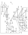
- a tomographic image acquisition system 500 as an aspect of the optical coherence tomographic image acquisition system according to the present embodiment will be described using FIG. 1.
- the entire optical system is mainly configured by a reflective optical system using mirrors that are a plurality of reflective members.
- the light source 601 in the present embodiment is a light source for emitting light (low coherence light) for irradiating an eye to be examined which is an inspection object.
- SLD Super Luminescent Diode
- the central wavelength is 830 nm, and the band is 50 nm.
- SLD is selected here as the type of light source, it is sufficient if low coherence light can be emitted, and ASE (Amplified Spontaneous Emission) or the like can also be used.
- ASE Ampliclified Spontaneous Emission
- near infrared light is suitable.
- the wavelength is preferably as short as possible in order to affect the lateral resolution of the obtained tomographic image.
- wavelengths may be selected depending on the measurement site to be observed.
- the wider the wavelength band the better the resolution in the depth direction.
- the central wavelength is 830 nm
- the light emitted from the light source 601 is guided through the single mode fiber 630-1 to the optical coupler 631 which is the dividing means in this embodiment, and is divided at an intensity ratio of 90:10 to become the reference light 605 and the measurement light 606 respectively.
- the division ratio is not limited to this, and an appropriate one is selected according to the inspection object.
- the reference beam 605 split by the optical coupler 631 is guided to the lens 635-1 through the single mode fiber 630-2 and adjusted to be a parallel beam with a beam diameter of 2 mm.
- the reference beam 605 is guided by the mirrors 614-2 to 3 to the mirror 614-15 which is a reference mirror.
- a plane mirror is used as a reference mirror.
- the light reflected by the mirror 614-15 is again reflected sequentially by the mirror 614-3 and the mirror 614-2 and guided to the optical coupler 631.
- the dispersion compensating glass 615 through which the reference beam 605 passes compensates for the dispersion when the measuring beam 606 reciprocates the eye to be inspected 607 and the lens 635-4 which are the inspection object, with respect to the reference beam 605.
- the mirror 614-15 is mounted on the motorized stage 617-1 and constitutes an optical path length adjusting means in the present embodiment.
- the motorized stage 617-1 can move in the direction shown by the arrow, and can adjust and control the optical path length of the reference beam 605.
- the movable range of the motorized stage 617-1 is 350 mm.
- the motorized stage 617-1 is controlled by a personal computer 625 which is control means in the present embodiment.
- the measuring beam 606 split by the optical coupler 631 is guided to a lens 635-4 through a single mode fiber 630-4 and adjusted to be a parallel beam with a beam diameter of 4 mm.
- the measuring beam 606 passes through the beam splitter 661-1, is reflected by the mirrors 614-5 to 6, and enters the deformable mirror 659.
- the deformable mirror 659 is a mirror device that corrects the aberration of the measurement light 606 and the return light 608 by freely deforming the mirror shape based on the aberration detected by the wavefront sensor 655.
- the deformable mirror is used as the wavefront correction device, as long as the aberration can be corrected, a spatial light phase modulator using liquid crystal or the like can also be used.
- the measurement light 606 is reflected by the mirrors 614-7 to 8 and enters the mirror of the XY scanner 619.
- the XY scanner 619 is described as one mirror for the sake of simplicity, but actually, two mirrors of the X scanning mirror and the Y scanning mirror are disposed close to each other, and the optical axis on the retina 627 Raster scan in the direction perpendicular to. Further, the center of the measurement light 606 is adjusted to coincide with the rotation center of the mirror of the XY scanner 619.
- the configuration of the XY scanner 619 is not limited to this, and an optical system is disposed between two mirrors of the XY scanner 619, and relays of positions conjugated with the pupil 626 are performed to arrange mirrors at each conjugated position. It may be
- the mirrors 614-9 to 1414 are optical systems for scanning the retina 627 of the fundus of the eye to be examined, and have a role of scanning the retina 627 with the measurement light 606 as a fulcrum around the pupil 626.
- the mirrors 614-11 to 12 are mounted on the motorized stage 617-2 as a set of reflecting members, and constitute the focus adjusting means in the present embodiment.
- the motorized stage 617-2 can move in the direction illustrated by the arrow, and can adjust the focus of the measurement light 606. This makes it possible to cope with the diopter of the subject eye 607.
- the movable range of the motorized stage 617-2 is 160 mm.
- the motorized stage 617-2 can be controlled by the personal computer 625 which is control means in this embodiment.
- the single mode fiber 630-4 to the mirror 614-14 constitute the measurement optical system in this embodiment.
- the measurement light 606 enters the eye to be examined 607, it is reflected or scattered from the retina 627 to become return light 608 and is guided to the optical coupler 631 again.
- the reference light 605 and the return light 608 are combined by the optical coupler 631 and further divided into 90:10.
- the combined light 642 is multiplexed by the transmission type grating 641 through the single mode fiber 630-3 and the lens 635-2, separated by wavelength by the lens 635-3, and the intensity of the light by the line camera 639. Are converted into voltage at each position (wavelength).
- interference fringes in the spectral region on the wavelength axis are observed on the line camera 639.
- the obtained voltage signal group is converted into a digital value, and data processing is performed by the personal computer 625 which is an image forming unit in the present embodiment, and a tomographic image is formed.
- the acquisition range in the depth direction of the tomographic image depends on the relationship (wavelength resolution) between the interference fringes and the number of pixels of the line camera 639 that receives the interference fringes.
- the number of pixels of the line camera 639 is 1000
- the acquisition range of the tomographic image is 2 mm.
- the formed tomographic image is displayed on a monitor (not shown) of the personal computer 625 which is the display means in the present embodiment by the personal computer 625 which is the display control means in the present embodiment.
- part of the return light 608 split by the beam splitter 661-1 is incident on the wavefront sensor 655, and the aberration of the return light 608 is measured.
- the wavefront sensor 655 uses a Shack-Hartmann wavefront sensor.
- the wavefront sensor 655 is electrically connected to the personal computer 625.
- the obtained aberration is expressed by the personal computer 625 using a Zernike polynomial. This shows the aberration of the subject eye 607.
- the position of the mirrors 614-11 to 12 is controlled using the motorized stage 617-2 to correct the diopter of the subject's eye.
- the surface shape of the deformable mirror 659 is controlled and corrected to enable acquisition of tomographic images with higher horizontal resolution.
- the mirrors 614-5 to 1414 are arranged so that the pupil 626, the XY scanner 619, the wavefront sensor 655, and the deformable mirror 659 are optically conjugate, and the wavefront sensor 655 measures the aberration of the eye 607 to be examined. It is possible to do.
- the anterior eye observation optical system includes a dichroic mirror 658-1, an anterior eye observation camera 656, and an anterior eye illumination light source (not shown).
- the dichroic mirror 658-1 reflects the infrared light of the anterior eye illumination light source and transmits the measurement light 606 and the return light 608.
- the optical axis of the anterior eye observation camera 656 is adjusted to coincide with the optical axis of the measurement optical system, and alignment of the XY position can be performed by observing the anterior segment of the subject eye 607 on the monitor .
- the focus of the anterior eye observation camera 656 is adjusted so as to focus on the iris of the eye 607 when it matches the working distance of the measurement optical system. Therefore, the Z position can be aligned by observing the iris on the monitor.
- an LED with a wavelength of 970 nm is used as the anterior eye illumination light source.
- a CCD camera is used as the anterior eye observation camera 656.
- the fixation lamp optical system includes a dichroic mirror 658-2 and a fixation lamp panel 657.
- the dichroic mirror 658-2 reflects the visible light of the fixation lamp panel 657 and transmits the measurement light 606 and the return light 608.
- the pattern displayed on the fixation lamp panel 657 is projected onto the retina of the subject eye 607 via the dichroic mirror 658-2.
- An organic EL panel is used for the fixation lamp panel 657.
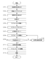
- the user presses an anterior illumination light source button (not shown) displayed on the monitor of the personal computer 625 in a state where the subject's eye to be examined is disposed at a predetermined position of the fundus image acquisition system 500 , Lights the anterior eye illumination light source (step S101).
- the anterior eye illumination light source is turned on, the anterior eye portion of the subject eye 607 photographed by the anterior eye observation camera 656 is displayed on the monitor.
- the anterior eye illumination light source When the anterior eye illumination light source is turned on, the user performs the anterior eye XYZ alignment while observing the anterior eye portion displayed on the monitor (step S102). As described above, since the XYZ observation position is adjusted, the anterior eye observation camera 656 adjusts the XYZ position of the apparatus so that the XY position of the anterior segment displayed on the monitor and the focus (Z) match.
- the user presses the anterior eye illumination light source button again to turn off the anterior eye illumination light source (step S103), and the user presses the light source button (not shown) displayed on the monitor. Lights up (step S104).
- the user instructs rough focus adjustment while viewing the Hartmann image of the wavefront sensor 655 displayed on the monitor (step S105).
- the motorized stage 617-2 moves, and the focus of the measurement light 606 is adjusted.
- a focus instruction focus adjustment is performed so that the vignetting by the measurement optical system of the light flux of the return light 608 entering the wavefront sensor 655 becomes as small as possible.
- the personal computer 625 moves the motorized stage 617-1 to adjust the light path length of the reference light 605 in accordance with the adjustment amount (variation amount) of the light path length of the measurement light 606 by the movement of the motorized stage 617-2.
- the relationship between the adjustment amount of the optical path length of the measurement light 606 and the movement amount of the motorized stage 617-2 for adjusting the optical path length of the reference light 605 will be described.
- the reference beam 605 reflected by the mirror 614-3 is reflected by the mirror 614-15 and returns to the mirror 614-3 again.
- the optical path length of the reference light 605 is changed by 2 ⁇ .
- the measurement light 606 is reflected by the mirror 614-10 and then reflected by the mirrors 614-11 to 12 and travels to the mirror 614-13.
- the return light 608 is reflected by the mirror 614-13 and then reflected by the mirrors 614-11-12 and returns to the mirror 614-10 again.
- the optical path length of the measurement light 606 changes by 4 ⁇ ′.
- the focus adjustment can be performed without changing the display position in the depth direction of the tomographic image.
- the movable range of the motorized stage 617-1 is 350 mm, and the movable range of the motorized stage 617-2 is 160 mm.
- the movable range of the motorized stage 617-1 is longer than twice that of the motorized stage 617-2 in addition to the adjustment amount of the optical path length of the measurement light 606 by focus adjustment, and the individual difference of the axial length of the subject eye
- a movable range of 30 mm ( ⁇ 15 mm) corresponds.
- step S110 When the motorized stage 617-1 of the optical path length adjusting means is moved in conjunction with the focus adjustment, the light path length adjustment described later (step S110) with respect to 350 mm which is the entire movable range of the motorized stage 617-1. It is sufficient to adjust only the movement range of 30 mm. Therefore, the adjustment range can be narrowly limited, and the time required for the adjustment can be shortened, so that the adjustment can be performed more easily.
- the user performs XY fine alignment while looking at the position of the Hartmann image (step S106).
- the wavefront sensor 655 is adjusted so that the center position of the sensor matches the optical axis of the measurement optical system. Therefore, the position of the subject's eye is adjusted according to the user's instruction so that the Hartmann image is in the center of the sensor.
- wavefront correction by the deformable mirror 659 is started in response to the user pressing a wavefront correction button (not shown) displayed on the monitor (step S107).
- the personal computer 625 deforms the shape of the deformable mirror 659 based on the aberration measured by the wavefront sensor 655 to correct the aberration of the eye to be examined.
- step S107 the user again performs rough focus adjustment of the measurement light 606 while viewing the tomographic image (step S107).
- the focus of the measurement light 606 is adjusted in response to the user moving the focus adjustment bar displayed on the monitor.
- the personal computer 625 moves the motorized stage 617-1 to adjust the light path length of the reference light 605 in accordance with the adjustment amount of the light path length of the measurement light 606 by the movement of the motorized stage 617-2.
- the tomographic image is observed in the tomographic image display area (not shown) on the monitor (step S109), but even if focus adjustment is performed, there may be cases where the tomographic image can not be observed. .
- This is the case where the optical path length difference between the measurement light 606 and the reference light 605 is large, and the tomographic image is out of the tomographic image display area.
- the optical path length is instructed by moving the optical path length adjustment bar (not shown) displayed on the monitor, and the optical path length of the reference beam 605 is appropriately changed (step S110).
- the process returns to rough focus adjustment (step S107) to perform adjustment.
- the tomographic image is displayed in the tomographic image display area is known to determine whether the luminance value of the vertical line corresponding to the A scan line in the area includes a luminance value equal to or greater than a predetermined value.
- the method of should be used.
- step S110 the change of the optical path length of the reference beam 605 (the optical path length instruction) performed in step S110 is performed within the movable range of 30 mm ( ⁇ 15 mm) of the motorized stage 617-1.
- the optical path length change (step S110) and the rough focus adjustment (step S107) are repeated until the tomographic image is observed in the tomographic image display area.
- the optical path length adjustment of the reference light is performed (step S111).
- the optical path length of the reference beam 605 is adjusted in response to the user moving the optical path length adjustment bar again so that the display position of the tomographic image matches the desired position in the tomographic image display area.
- the personal computer 625 does not perform control to move the motorized stage 617-2 in accordance with the adjustment amount of the optical path length of the reference light 605 by the movement of the motorized stage 617-1.
- the display position in the depth direction of the tomographic image can be adjusted while maintaining the focus state adjusted in step S108.
- fine focus adjustment of the measurement light 606 is performed according to the user moving the focus adjustment bar displayed on the monitor (step S112).
- fine focus adjustment is performed so that the measurement light 606 is particularly focused on the layer to be photographed.
- the personal computer 625 moves the motorized stage 617-1 to adjust the light path length of the reference light 605 in accordance with the adjustment amount of the light path length of the measurement light 606 by the movement of the motorized stage 617-2. Do. Accordingly, it is possible to adjust only the focus position while maintaining the display position in the depth direction of the tomographic image adjusted in step S111.
- a tomographic image is acquired in response to the user pressing an imaging button (not shown) displayed on the monitor (step S113).
- the combined light of the measurement light 606 and the reference light 605 is received by the line camera 639 and converted into a voltage signal. Further, the obtained voltage signal group is converted into a digital value, and data is stored and processed by the personal computer 625.
- the optical path length of the reference light 605 by adjusting the optical path length of the reference light 605 according to the adjustment amount of the optical path length generated at the time of focus adjustment of the measurement light 606, the time required for focus adjustment and display position adjustment of the tomographic image is shortened. You can easily make adjustments.
- a fundus oculi image acquisition system 501 as one aspect of the optical coherence tomographic image acquisition system according to the present embodiment will be described with reference to FIG.
- the basic configuration of the image acquisition system 501 is the same as that of the fundus image acquisition system 500 according to the first embodiment. However, it differs from the fundus oculi image acquisition system 500 in that a scanning laser ophthalmoscope (SLO: Scanning Laser Ophthalmoscope) for fundus oculi observation of the subject's eye to be examined is added.
- SLO Scanning Laser Ophthalmoscope
- the light source 602 in the present embodiment is a light source for emitting light of a wavelength different from that of the light source 601.
- an SLD with a wavelength of 780 nm is used.
- the SLD was selected as the type of light source here, LD (Laser Diode) or the like can also be used.
- the light emitted from the light source 602 is guided to a lens 635-5, and adjusted to be a parallel light having a beam diameter of 4 mm.
- the light having passed through the lens 635-5 is guided to the beam splitter 661-2, and is split at an intensity ratio of 90:10 between the transmitted light and the reflected light (observation light 609).
- the observation light 609 reflected by the beam splitter 661-2 travels to the dichroic mirror 658-5.
- the dichroic mirror 658-5 transmits light of the wavelength of the light source 601 and reflects light of the wavelength of the light source 602.
- the observation light 609 reflected by the dichroic mirror 658-5 passes through the optical path common to the measurement light 606 and passes through the beam splitter 661-1, the mirrors 614-5 to 6, the deformable mirror 659, and the mirror 614-7. , Is reflected by the mirror 614-8.
- the dichroic mirrors 658-3 transmit light of the wavelength of the light source 601 and reflect light of the wavelength of the light source 602.
- the observation light 609 reflected by the mirror 614-8 is reflected by the dichroic mirror 658-3 and enters the mirror of the XY scanner 620.
- the XY scanner 620 is described as one mirror for the sake of simplicity, but actually, two mirrors of the X scanning mirror and the Y scanning mirror are disposed close to each other, and the optical axis on the retina 627 Raster scan in the direction perpendicular to. Also, the center of the observation light is adjusted to coincide with the rotation center of the mirror of the XY scanner 620.
- the XY scanner 619 of the measurement light 606 and the XY scanner 620 of the observation light 609 are separately disposed. Thereby, since the measurement light 606 and the observation light 609 can be scanned separately, the imaging range and the observation range can be set independently.
- the scanning speed of the measurement light 606 is limited by the reading speed of the line camera 639
- the scanning speed of the observation light 609 can be increased by separately setting the XY scanner, and the frame rate of acquisition of the fundus front image is You can raise it. This is advantageous to increase the accuracy when, for example, the movement of the subject's eye is detected from the front image of the fundus to perform position correction (tracking) of image photographing.
- a galvano mirror is used for the XY scanner of the measurement light 606, a resonant mirror for the X scanner of the observation light 609, and a galvano mirror for the Y scanner.
- the observation light 609 reflected by the XY scanner 620 is reflected by the dichroic mirror 658-4, and is again irradiated to the eye to be examined 607 through a common optical path with the measurement light 606.
- the observation light 609 reflected by the fundus 627 returns to the opposite optical path, is reflected by the dichroic mirror 658-5, and passes through the beam splitter 661-2.
- the intensity ratio of the transmitted light (observation light 609) to the reflected light is 90:10.
- the observation light 609 transmitted through the beam splitter 661-2 is collected by the lens 635-6 and passes through the pinhole plate 660.
- the pinhole plate 660 is adjusted to a position conjugate with the fundus, and acts as a confocal stop that blocks unnecessary light from other than the conjugate point.
- the lens 635-5 to the mirror 614-14, the lens 635-6, and the pinhole plate 660 constitute an observation optical system in this embodiment.
- the observation light 609 having passed through the pinhole is received by the light receiving element 640.
- an APD Anavalanche Photo Diode
- the light intensity received by the APD is converted to a voltage signal.
- the obtained voltage signal group is converted into a digital value, and data processing is performed by the personal computer 625 to form a fundus front image.
- the formed fundus front image is displayed on the monitor of the personal computer 625.
- part of the return light 608 split by the beam splitter 661-1 is incident on the wavefront sensor 655, and the aberration of the return light 608 is measured.
- the beam splitter 661-1 reflects a part of the return light 608 and transmits the observation light 609. Thereby, the aberration of the return light 608 can be selectively measured.
- steps S201 to S203 alignment of the anterior segment is performed as in steps S101 to S103 in the first embodiment.
- the light source 601 and the light source 602 are turned on in response to the user pressing a light source button (not shown) displayed on the monitor (step S204).
- a light source button (not shown) displayed on the monitor (step S204).
- the timing of lighting the light source 601 is not limited to this. For example, it may be after rough focus adjustment at step S205 or after XY fine alignment at step S206.
- the user When the light source 602 is turned on, the user performs rough focus adjustment while looking at the fundus front image acquired by the observation optical system (step S205).
- the motorized stage 617-2 moves.
- the motorized stage 617-2 and the mirrors 614-11 to 12 are disposed in the common optical path of the measurement light 606 and the observation light 609, and by performing focus adjustment of the observation light 609, the measurement light 606 is also interlocked simultaneously.
- Rough focus adjustment is performed.
- focus adjustment is performed so that the luminance of the fundus front image is maximized.
- the personal computer 625 moves the motorized stage 617-1 to adjust the light path length of the reference light 605 in accordance with the adjustment amount of the light path length of the measurement light 606 by the movement of the motorized stage 617-2.
- step S206 When the luminance of the fundus front image is maximized by rough focus adjustment, XY fine alignment is performed (step S206) as in the first embodiment, and wavefront correction by the deformable mirror 659 is started (step S207).
- the optical path length of the reference light 605 is adjusted according to the user moving the optical path length adjustment bar (not shown) displayed on the monitor (step S208).
- the display position of the tomographic image is adjusted to fit the desired position in the tomographic image display area.
- the personal computer 625 does not perform control to move the motorized stage 617-2 in accordance with the adjustment amount of the optical path length of the reference light 605 by the movement of the motorized stage 617-1.
- the adjustment of the optical path length of the reference beam 605 performed in step S208 is performed within the movement range of 30 mm ( ⁇ 15 mm) of the motorized stage 617-1 which is an adjustment range for individual differences of the axial length.
- fine focus adjustment of the measurement light 606 is performed as in the first embodiment (step S209).
- step S205 the personal computer 625 moves the motorized stage 617-1 according to the adjustment amount of the light path length of the measurement light 606 by the movement of the motorized stage 617-2 to set the light path length of the reference light 605. adjust. Accordingly, it is possible to adjust only the focus position while maintaining the display position in the depth direction of the tomographic image adjusted in step S208.
- a tomographic image is acquired in response to the user pressing an imaging button (not shown) displayed on the monitor (step S210).
- the combined light of the measurement light 606 and the reference light 605 is received by the line camera 639 and converted into a voltage signal. Further, the obtained voltage signal group is converted into a digital value, and data is stored and processed by the personal computer 625.
- the observation optical system is added to the first embodiment, and the focus adjustment of the observation light 609 and the measurement light 606 is interlocked, thereby shortening the time required for the rough focus adjustment of the measurement light 606, Adjustments can be made more easily.
- a fundus oculi image acquisition system 502 as an aspect of the optical coherence tomographic image acquisition system according to the present embodiment will be described with reference to FIG.
- the basic configuration of the fundus image acquisition system 502 is the same as that of the fundus image acquisition system 500 according to the first embodiment. However, it differs in that a mirror 614-1 and a mirror 614-4 are used instead of the mirror 614-15 arranged in the reference light path in the first embodiment.
- the optical path of the reference beam 605 in this embodiment will be described.
- the reference beam 605 split by the optical coupler 631 is guided to the lens 635-1 through the single mode fiber 630-2 and adjusted to be a parallel beam with a beam diameter of 2 mm.
- the reference beam 605 is guided by the mirrors 614-2 to 3 to the mirror 614-1 which is a reference mirror.
- a retroreflector is used as a reference mirror.
- the light emitted from the mirror 614-1 is reflected by the mirror 614-4, reflected again by the mirror 614-1, the mirror 614-3, and the mirror 614-2 and guided to the optical coupler 631.
- the mirror 614-1 is mounted on the motorized stage 617-1 and constitutes an optical path length adjusting means in the present embodiment.
- the motorized stage 617-1 can move in the direction shown by the arrow, and can adjust the optical path length of the reference beam 605.
- the movable range of the motorized stage 617-1 is 175 mm.
- the motorized stage 617-1 is controlled by a personal computer 625 which is control means in the present embodiment.
- the reference light 605 reflected by the mirror 614-3 is reflected by the mirror 614-1 and travels to the mirror 614-4, and the reference light 605 reflected by the mirror 614-4 is the mirror 614-1. It is reflected by and returns to the mirror 614-3.
- the optical path length of the reference light 605 changes by 4 ⁇ .
- the movable range of the motorized stage 617-1 is 175 mm
- the movable range of the motorized stage 617-2 is 160 mm as in the first embodiment.
- the movable range of the motorized stage 617-1 is longer than that of the motorized stage 617-2 in addition to the adjustment amount of the optical path length of the measurement light 606 by focus adjustment and the adjustment amount of the optical path length due to individual differences in axial length.
- a movable range of 15 mm ( ⁇ 7.5 mm) corresponds.
- the movable range of the motorized stage 617-1 can be suppressed narrow compared to the first embodiment. Therefore, it becomes unnecessary to secure a space for moving the motorized stage, which is advantageous for downsizing of the apparatus.
- the moving amounts of the motorized stage 617-1 and the motorized stage 617-2 are the same amount, they may be configured using the same motorized stage.
- a motorized stage having only the mirror 614-1 mounted thereon is further disposed on the same motorized stage.
- the movable range of the motorized stage may be 15 mm, a smaller stage can be used, which is advantageous for downsizing of the apparatus.
- the optical path length of the reference light 605 is adjusted in conjunction with the adjustment of the optical path length of the measurement light 606 by focus adjustment.
- FIG. 6 shows a tomographic image display area displayed on the monitor, and a broken line schematically shows a tomographic image of the retina of the fundus of the subject's eye.
- the upper end of the tomographic image display area is a position (coherence gate position) where the optical path lengths of the measurement light 606 and the reference light 605 are equal.
- the interference fringes become higher frequency and the SN ratio of the image decreases.
- the noise of the DC component of the interference fringes also lowers the SN ratio of the image. Therefore, here, a range slightly away from the upper end of the tomographic image display area (a range of a shown by a dashed dotted line in FIG. 6) is set as the predetermined range.
- the tomographic image is also moved in the vertical direction (depth direction) due to a change in the optical path length of the measurement light 606 accompanying the focus adjustment.
- the focus adjustment is performed. And does not adjust the optical path length of the reference beam 605.
- the focus adjustment of the measurement light 606 and the display position adjustment of the tomographic image in the depth direction can be performed simultaneously, and the time required to adjust the optical path length of the reference light 605 can be shortened.
- the predetermined amount of focus adjustment for determining the increase or decrease of the luminance integral value may be set as appropriate, such as an amount corresponding to about 1/10 of the predetermined range of the tomographic image.
- luminance integral value within the predetermined range is used as a parameter
- the tomographic image may be binarized with a predetermined threshold, and the number of pixels above the predetermined threshold within a predetermined range may be used as an index.
- the predetermined threshold may be appropriately set in advance based on the brightness of the image obtained by photographing the human eye and the model eye.
- the optical path length of the reference light 605 is adjusted by the same amount as the adjustment amount of the optical path length of the measurement light 606 by focus adjustment.
- the present invention is not limited thereto.
- the axial length tends to differ depending on diopter.
- the eye axial length tends to be long in the myopic eye, and the eye axial length tends to be short in the hyperopic eye. Therefore, when adjusting the optical path length of the reference beam 605 in conjunction with focus adjustment, control may be performed to adjust the optical path length of the reference beam 605 by adding a predetermined offset amount according to the diopter.
- the offset amount can be determined in advance by measuring the axial length of the subject's eye with various diopters in advance and performing fitting processing of the measured value using a mathematical expression. This may be stored in the personal computer 625, and the amount of movement of the stage 617-1 may be controlled by adding the amount of offset stored in the amount of adjustment of the optical path length of the measurement light 606 at the time of focus adjustment. This increases the possibility that the adjustment amount of the optical path length of the reference beam 605 after rough focus adjustment can be reduced, so the time required for adjusting the optical path length of the reference beam 605 can be further shortened and the adjustment can be performed more easily. It will be advantageous.
- the fine focus adjustment of step S112 and step S209 is performed by the focus adjustment unit of the measurement optical system.
- the deformable mirror 659 may be used.
- fine focus adjustment is performed by deforming the shape of the deformable mirror 659.
- the optical path length of the measurement light 606 does not change due to the focus adjustment, the optical path length of the reference light 605 is not adjusted in conjunction with the focus adjustment.
- fine focus adjustment can be performed without changing the display position in the depth direction of the tomographic image.
- the focus adjustment of the measurement light 606 and the observation light 609 is performed using a common optical system, but it may be separate optical systems.
- the measurement light 606 and the observation light 609 are branched between the focus adjustment means of the measurement light 606 and the eye to be examined, and mirrors for focus adjustment are disposed in the light path of the measurement light 606 and the light path of the observation light 609, respectively. Perform focus adjustment by moving them in conjunction with each other.
- the position of the mirror for focus adjustment with respect to each diopter is obtained in advance from simulation or actual measurement using a tool or the like, and the position data is stored in the personal computer 625.
- the mirror for the focus adjustment of the measurement light 606 is moved by the movement amount stored in the personal computer 625.
- the focus adjustment of the measurement light 606 can be performed in conjunction with the focus adjustment of the observation light 609, the time required for the rough focus adjustment can be shortened, and the adjustment can be performed more easily.
- the optical system for adjusting the focus of the observation light 609 is not limited to the mirrors that are a plurality of reflecting members, and may be configured of a plurality of lenses.
- spectral domain OCT using a broadband light source in which light irradiated to the eye to be examined 607 generates broadband light is used.
- the present invention is not limited to this, and may be applied to, for example, wavelength sweeping OCT using a light source that generates light for sweeping the wavelength.
- the present invention can also be applied to subjects such as skin and organs other than the eye.
- the present invention has an aspect as a medical device such as an endoscope other than the ophthalmologic imaging apparatus. Therefore, it is preferable that the present invention is grasped as an image acquisition device exemplified by an ophthalmologic photographing apparatus, and an eye to be examined is grasped as one mode of a subject.
- the present invention can also be achieved by configuring the device as follows. That is, a recording medium (or storage medium) storing a program code (computer program) of software for realizing the functions of the above-described embodiments may be supplied to a system or an apparatus. In addition to the aspect of the recording medium, a computer readable recording medium may be used. Then, the computer (or CPU or MPU) of the system or apparatus reads out and executes the program code stored in the recording medium. In this case, the program code itself read out from the recording medium realizes the functions of the above-described embodiments, and the recording medium recording the program code constitutes the present invention. Also, the embodiments can be implemented by circuitry (eg, an ASIC) that implements one or more functions.
- circuitry eg, an ASIC
Landscapes
- Health & Medical Sciences (AREA)
- Life Sciences & Earth Sciences (AREA)
- Physics & Mathematics (AREA)
- General Health & Medical Sciences (AREA)
- General Physics & Mathematics (AREA)
- Radiology & Medical Imaging (AREA)
- Nuclear Medicine, Radiotherapy & Molecular Imaging (AREA)
- Engineering & Computer Science (AREA)
- Biomedical Technology (AREA)
- Biophysics (AREA)
- Surgery (AREA)
- Animal Behavior & Ethology (AREA)
- Medical Informatics (AREA)
- Public Health (AREA)
- Veterinary Medicine (AREA)
- Heart & Thoracic Surgery (AREA)
- Ophthalmology & Optometry (AREA)
- Molecular Biology (AREA)
- Automation & Control Theory (AREA)
- Optics & Photonics (AREA)
- Chemical & Material Sciences (AREA)
- Analytical Chemistry (AREA)
- Biochemistry (AREA)
- Immunology (AREA)
- Pathology (AREA)
- Eye Examination Apparatus (AREA)
Priority Applications (1)
| Application Number | Priority Date | Filing Date | Title |
|---|---|---|---|
| US16/796,655 US11134841B2 (en) | 2017-08-28 | 2020-02-20 | Image acquisition apparatus and method for controlling the same |
Applications Claiming Priority (2)
| Application Number | Priority Date | Filing Date | Title |
|---|---|---|---|
| JP2017-163475 | 2017-08-28 | ||
| JP2017163475A JP2019037650A (ja) | 2017-08-28 | 2017-08-28 | 画像取得装置およびその制御方法 |
Related Child Applications (1)
| Application Number | Title | Priority Date | Filing Date |
|---|---|---|---|
| US16/796,655 Continuation US11134841B2 (en) | 2017-08-28 | 2020-02-20 | Image acquisition apparatus and method for controlling the same |
Publications (1)
| Publication Number | Publication Date |
|---|---|
| WO2019044457A1 true WO2019044457A1 (ja) | 2019-03-07 |
Family
ID=65525393
Family Applications (1)
| Application Number | Title | Priority Date | Filing Date |
|---|---|---|---|
| PCT/JP2018/030043 Ceased WO2019044457A1 (ja) | 2017-08-28 | 2018-08-10 | 画像取得装置およびその制御方法 |
Country Status (3)
| Country | Link |
|---|---|
| US (1) | US11134841B2 (https=) |
| JP (1) | JP2019037650A (https=) |
| WO (1) | WO2019044457A1 (https=) |
Cited By (1)
| Publication number | Priority date | Publication date | Assignee | Title |
|---|---|---|---|---|
| WO2020257582A1 (en) * | 2019-06-20 | 2020-12-24 | Duke University | Systems and methods for multiplexing and alternating light of different wavelengths in an ophthalmoscope |
Families Citing this family (2)
| Publication number | Priority date | Publication date | Assignee | Title |
|---|---|---|---|---|
| US11499813B2 (en) * | 2017-10-09 | 2022-11-15 | Nederlandse Organisatie Voor Toegepast-Natuurwetenschappelijk Onderzoek Tno | Refocusing device |
| US20250255482A1 (en) * | 2024-02-13 | 2025-08-14 | Identifeye Health Inc. | Digital light processing (dlp) for fundus imaging |
Citations (7)
| Publication number | Priority date | Publication date | Assignee | Title |
|---|---|---|---|---|
| JP2004191114A (ja) * | 2002-12-10 | 2004-07-08 | Naohiro Tanno | 光コヒーレンストモグラフィーにおける光干渉計一体駆動による検知点走査方法及び光コヒーレンストモグラフィー装置 |
| US20080024767A1 (en) * | 2006-07-28 | 2008-01-31 | Peter Seitz | Imaging optical coherence tomography with dynamic coherent focus |
| JP2013153798A (ja) * | 2012-01-26 | 2013-08-15 | Canon Inc | 光断層撮像装置および制御方法 |
| JP2015049204A (ja) * | 2013-09-04 | 2015-03-16 | 株式会社日立エルジーデータストレージ | 光計測装置及び光断層観察方法 |
| JP2015221091A (ja) * | 2014-05-22 | 2015-12-10 | 株式会社トプコン | 眼科装置 |
| JP2016049368A (ja) * | 2014-09-01 | 2016-04-11 | 株式会社ニデック | 眼科撮影装置 |
| WO2016121249A1 (ja) * | 2015-01-30 | 2016-08-04 | 浜松ホトニクス株式会社 | 干渉光学装置、干渉観察装置および干渉観察方法 |
Family Cites Families (14)
| Publication number | Priority date | Publication date | Assignee | Title |
|---|---|---|---|---|
| EP2278266A3 (en) * | 2004-11-24 | 2011-06-29 | The General Hospital Corporation | Common-Path Interferometer for Endoscopic OCT |
| EP1887312A1 (en) | 2006-07-28 | 2008-02-13 | Heliotis AG | Imaging optical coherence tomography with dynamic coherent Focus |
| US8395781B2 (en) * | 2007-07-12 | 2013-03-12 | Volcano Corporation | Automatic calibration systems and methods of use |
| US8125645B2 (en) * | 2008-03-31 | 2012-02-28 | Fujifilm Corporation | Optical tomographic imaging system, tomographic image acquiring method, and optical tomographic image forming method |
| JP5331395B2 (ja) * | 2008-07-04 | 2013-10-30 | 株式会社ニデック | 光断層像撮影装置 |
| JP5794664B2 (ja) * | 2011-01-20 | 2015-10-14 | キヤノン株式会社 | 断層画像生成装置及び断層画像生成方法 |
| JP6007527B2 (ja) | 2012-03-13 | 2016-10-12 | 株式会社ニデック | 眼底撮影装置 |
| JP6429447B2 (ja) * | 2013-10-24 | 2018-11-28 | キヤノン株式会社 | 情報処理装置、比較方法、位置合わせ方法及びプログラム |
| JP2016041221A (ja) * | 2014-08-19 | 2016-03-31 | 株式会社トプコン | 眼科撮影装置およびその制御方法 |
| JP6808383B2 (ja) * | 2015-09-30 | 2021-01-06 | キヤノン株式会社 | 光干渉断層撮影装置、その制御方法および光干渉断層撮影システム |
| US11452442B2 (en) * | 2016-06-15 | 2022-09-27 | Oregon Health & Science University | Systems and methods for automated widefield optical coherence tomography angiography |
| JP6731868B2 (ja) * | 2017-02-17 | 2020-07-29 | 株式会社Screenホールディングス | 撮像方法および撮像装置 |
| JP6929684B2 (ja) * | 2017-04-06 | 2021-09-01 | キヤノン株式会社 | 眼科撮影装置及びその制御方法 |
| WO2019117036A1 (ja) * | 2017-12-14 | 2019-06-20 | キヤノン株式会社 | 撮像装置及びその制御方法 |
-
2017
- 2017-08-28 JP JP2017163475A patent/JP2019037650A/ja active Pending
-
2018
- 2018-08-10 WO PCT/JP2018/030043 patent/WO2019044457A1/ja not_active Ceased
-
2020
- 2020-02-20 US US16/796,655 patent/US11134841B2/en not_active Expired - Fee Related
Patent Citations (7)
| Publication number | Priority date | Publication date | Assignee | Title |
|---|---|---|---|---|
| JP2004191114A (ja) * | 2002-12-10 | 2004-07-08 | Naohiro Tanno | 光コヒーレンストモグラフィーにおける光干渉計一体駆動による検知点走査方法及び光コヒーレンストモグラフィー装置 |
| US20080024767A1 (en) * | 2006-07-28 | 2008-01-31 | Peter Seitz | Imaging optical coherence tomography with dynamic coherent focus |
| JP2013153798A (ja) * | 2012-01-26 | 2013-08-15 | Canon Inc | 光断層撮像装置および制御方法 |
| JP2015049204A (ja) * | 2013-09-04 | 2015-03-16 | 株式会社日立エルジーデータストレージ | 光計測装置及び光断層観察方法 |
| JP2015221091A (ja) * | 2014-05-22 | 2015-12-10 | 株式会社トプコン | 眼科装置 |
| JP2016049368A (ja) * | 2014-09-01 | 2016-04-11 | 株式会社ニデック | 眼科撮影装置 |
| WO2016121249A1 (ja) * | 2015-01-30 | 2016-08-04 | 浜松ホトニクス株式会社 | 干渉光学装置、干渉観察装置および干渉観察方法 |
Cited By (2)
| Publication number | Priority date | Publication date | Assignee | Title |
|---|---|---|---|---|
| WO2020257582A1 (en) * | 2019-06-20 | 2020-12-24 | Duke University | Systems and methods for multiplexing and alternating light of different wavelengths in an ophthalmoscope |
| US12089897B2 (en) | 2019-06-20 | 2024-09-17 | Duke University | Systems and methods for multiplexing and alternating light of different wavelengths in an ophthalmoscope |
Also Published As
| Publication number | Publication date |
|---|---|
| JP2019037650A (ja) | 2019-03-14 |
| US11134841B2 (en) | 2021-10-05 |
| US20200187773A1 (en) | 2020-06-18 |
Similar Documents
| Publication | Publication Date | Title |
|---|---|---|
| JP7179523B2 (ja) | 眼底撮像装置、眼底撮像方法およびプログラム | |
| KR101670698B1 (ko) | 광간섭 단층촬상장치 및 그 제어 방법 | |
| US7824035B2 (en) | Ophthalmic photographing apparatus | |
| US8651662B2 (en) | Optical tomographic imaging apparatus and imaging method for optical tomographic image | |
| US20200297209A1 (en) | Imaging apparatus and control method therefor | |
| KR20130086969A (ko) | 광 간섭 단층 촬상 장치, 광 간섭 단층 촬상 장치 제어 방법 및 저장 매체 | |
| JP2011172822A (ja) | 光断層像撮影装置 | |
| JP6552200B2 (ja) | 光断層撮像装置、その制御方法、及びプログラム | |
| JP2010169502A (ja) | 光断層画像撮像装置 | |
| JP7027698B2 (ja) | 眼科撮影装置 | |
| JP5997457B2 (ja) | 撮像装置及び撮像装置の制御方法 | |
| JP6901264B2 (ja) | 眼科装置 | |
| US11134841B2 (en) | Image acquisition apparatus and method for controlling the same | |
| JP7129162B2 (ja) | 眼底撮像装置 | |
| JP6779674B2 (ja) | Oct装置 | |
| JP7123628B2 (ja) | 眼底撮影装置およびその制御方法 | |
| JP7086688B2 (ja) | 画像撮影装置およびその制御方法 | |
| JP7123626B2 (ja) | 眼底撮影装置およびその制御方法 | |
| JP2015198723A (ja) | 眼科装置 | |
| JP7309404B2 (ja) | 撮像装置およびその制御方法 | |
| JP2019063243A (ja) | 眼科撮影装置 | |
| JP7029324B2 (ja) | 光源制御装置、眼科装置、及び光源制御方法 | |
| JP2026016988A (ja) | 眼科装置 | |
| JP6916011B2 (ja) | 眼科装置 | |
| JP2016083318A (ja) | 眼科装置および眼科装置の制御方法 |
Legal Events
| Date | Code | Title | Description |
|---|---|---|---|
| 121 | Ep: the epo has been informed by wipo that ep was designated in this application |
Ref document number: 18851423 Country of ref document: EP Kind code of ref document: A1 |
|
| NENP | Non-entry into the national phase |
Ref country code: DE |
|
| 122 | Ep: pct application non-entry in european phase |
Ref document number: 18851423 Country of ref document: EP Kind code of ref document: A1 |