WO2019039244A1 - 樹脂封止型車載電子制御装置 - Google Patents
樹脂封止型車載電子制御装置 Download PDFInfo
- Publication number
- WO2019039244A1 WO2019039244A1 PCT/JP2018/029344 JP2018029344W WO2019039244A1 WO 2019039244 A1 WO2019039244 A1 WO 2019039244A1 JP 2018029344 W JP2018029344 W JP 2018029344W WO 2019039244 A1 WO2019039244 A1 WO 2019039244A1
- Authority
- WO
- WIPO (PCT)
- Prior art keywords
- connector housing
- resin
- sealed
- control device
- electronic control
- Prior art date
- Legal status (The legal status is an assumption and is not a legal conclusion. Google has not performed a legal analysis and makes no representation as to the accuracy of the status listed.)
- Ceased
Links
Images




Classifications
-
- B—PERFORMING OPERATIONS; TRANSPORTING
- B60—VEHICLES IN GENERAL
- B60R—VEHICLES, VEHICLE FITTINGS, OR VEHICLE PARTS, NOT OTHERWISE PROVIDED FOR
- B60R16/00—Electric or fluid circuits specially adapted for vehicles and not otherwise provided for; Arrangement of elements of electric or fluid circuits specially adapted for vehicles and not otherwise provided for
- B60R16/02—Electric or fluid circuits specially adapted for vehicles and not otherwise provided for; Arrangement of elements of electric or fluid circuits specially adapted for vehicles and not otherwise provided for electric constitutive elements
-
- H—ELECTRICITY
- H01—ELECTRIC ELEMENTS
- H01R—ELECTRICALLY-CONDUCTIVE CONNECTIONS; STRUCTURAL ASSOCIATIONS OF A PLURALITY OF MUTUALLY-INSULATED ELECTRICAL CONNECTING ELEMENTS; COUPLING DEVICES; CURRENT COLLECTORS
- H01R13/00—Details of coupling devices of the kinds covered by groups H01R12/70 or H01R24/00 - H01R33/00
- H01R13/46—Bases; Cases
-
- H—ELECTRICITY
- H05—ELECTRIC TECHNIQUES NOT OTHERWISE PROVIDED FOR
- H05K—PRINTED CIRCUITS; CASINGS OR CONSTRUCTIONAL DETAILS OF ELECTRIC APPARATUS; MANUFACTURE OF ASSEMBLAGES OF ELECTRICAL COMPONENTS
- H05K5/00—Casings, cabinets or drawers for electric apparatus
Definitions
- the present invention relates to a resin-sealed on-vehicle electronic control device.
- an electronic control unit such as an engine control unit or an automatic transmission control unit mounted on a vehicle
- the calorific value With the increase of the calorific value, the demand for exposure to high temperature environment, vibration resistance and impact resistance is increasing.
- a technique in which a circuit board for mounting an electronic component and a connector housing for connecting external terminals are integrally sealed with a resin (for example, see Patent Document 1). According to such a technique, since the circuit board or the like is sealed with a resin, it is considered to be advantageous for heat resistance, vibration resistance and impact resistance.
- the present invention has been made based on the above circumstances, and an object thereof is a resin-sealed on-vehicle electronic device capable of reliably preventing separation of a connector housing and a sealing resin with a simple configuration. It is in providing a control device.
- the present invention (1) A circuit board on which electronic components are mounted, a connector housing for electrically connecting the circuit board to an external terminal, and at least a part of the outer periphery of the connector housing and at least a part of the circuit board And a sealing resin for fixing the connector housing to the circuit board.
- a concave and / or convex structure extending in a direction transverse to the direction in which the external terminal is mounted in a region of the outer periphery of the connector housing covered by the sealing resin.
- Resin-sealed on-vehicle electronic control device characterized by (2) The resin-sealed on-vehicle electronic control device according to (1), wherein the linear expansion coefficient of the connector housing is larger than the linear expansion coefficient of the sealing resin, (3) The resin-sealed on-vehicle electronic control device according to the above (1) or (2), wherein the shape of the structure is a shape that goes around at least one circumference of the connector housing. (4) The resin-sealed vehicle-mounted electronic according to any one of (1) to (3), wherein the shape of the structure is a single annular or spiral convex shape that goes around the outer periphery of the connector housing.
- Control device (5) The resin-sealed in-vehicle electronic control device according to (4), wherein the structure has at least one through hole along the same direction as the direction in which the external terminal is mounted; (6) In the direction in which the external terminal is mounted, the portion where the structure is formed is the end of the connector housing on the side opposite to the end of the connector housing on which the external terminal is mounted.
- the resin-sealed in-vehicle electronic control device according to any one of the above (1) to (5) which is located in a portion close to the portion, and (7) covering the boundary portion between the connector housing and the sealing resin
- the resin-sealed on-vehicle electronic control device according to any one of the above (1) to (6) which comprises an elastic member.
- the "external terminal” means the terminal of apparatuses other than resin-sealed vehicle-mounted electronic control apparatus electrically connected with the terminal in a connector housing.
- the “direction in which the external terminal is attached” means the direction in which the external terminal is moved when the external terminal is attached to the connector housing.
- the present invention can provide a resin-sealed on-vehicle electronic control device capable of reliably preventing separation of the connector housing and the sealing resin with a simple configuration.
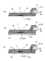
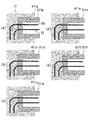
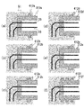
- FIG. 6 is a schematic cross-sectional view showing an enlarged main part of the present invention, wherein (a) to (e) each show an example of a concave-shaped structure.
- FIG. 6 is a schematic cross-sectional view showing an enlarged main part of the present invention, wherein (a) to (f) each show an example of a convex-shaped structure.
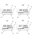
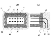
- FIG. 1 is a schematic plan view showing a structure of the present invention, wherein (a) to (d) each show an example of the arrangement of the structure. It is the schematic which shows the connector housing of FIG. 1 and is expanded, (a) is a side view, (b) has each shown the sectional view cut by the A-A 'line of (a). It is a schematic sectional drawing which shows an example of the formation method of the resin-sealed vehicle-mounted electronic control apparatus of FIG.
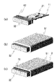
- Fig. 10 is a schematic perspective view of Fig. 9, in which (a) shows the state before forming the sealing resin, (b) shows the state before forming the elastic member, and (c) shows the state after forming the elastic member. There is.
- the resin-sealed on-vehicle electronic control device includes a circuit board on which electronic components are mounted, a connector housing for electrically connecting the circuit board and an external terminal, and at least a part of an outer periphery of the connector housing.
- a resin-sealed on-vehicle electronic control device that covers at least a part of the circuit board and includes a sealing resin that fixes the connector housing to the circuit board, wherein the connector housing is the resin sealing In the region of the outer periphery of the connector housing covered by the resin block, it has a concave and / or convex structure extending in a direction transverse to the mounting direction of the external terminal. It features.
- FIG. 1 is a schematic cross-sectional view showing a first embodiment of the present invention.
- the resin-sealed on-vehicle electronic control device 1 is generally configured by a circuit board 11, a connector housing 31, and a sealing resin 51, as shown in FIG.
- the electronic component 21 is mounted on the circuit board 11.
- electronic components 21 including heat generating electronic components 211 such as capacitors and resistors are joined to the circuit substrate 11 by soldering or the like, as shown in FIG.
- a terminal 212 is provided for connection to an external terminal.
- a metal base for heat dissipation may be attached to the circuit board 11 via a thermally conductive spacer 23.
- a metal base 221 having a radiation fin is shown in FIG. 2B, and a flat metal base 222 is shown in FIG. 2C.
- the connector housing 31 electrically connects the circuit board 11 and the external terminal. As shown in FIG. 1, the connector housing 31 has a terminal 213 in the opening c 1, and the terminal 213 and the terminal 212 of the circuit board 11 described above are connected by a metal wire 33.
- a surface mount type connector housing 311a as shown in FIG. 2 (a) a pin insertion type connector housing 311b as shown in FIGS. 2 (b) and 2 (c), etc. Can.
- the connector housing 31 is extended in a direction crossing the direction in which the external terminal is mounted in the region of the outer periphery 31a of the connector housing 31 covered by the sealing resin 51 described later.
- the structure 41 has a concave shape and / or a convex shape.
- the specific shape of the structure 41 may be any shape as long as the concave shape and the convex shape are respectively recessed or protruded from the height of the periphery of the structure 41 in the connector housing 31.
- a structure with a concave shape of a cut surface is a rectangular concave structure 411b (see FIG. 3A) and a structure 411f (see FIG. 3E), a semicircular concave structure Body 411c (see FIG. 3 (b)), triangular concave structure 411d (see FIG. 3 (c)), deep-opened structure 411 e (see FIG. 3 (d)), rectangular shape of the cut surface
- the structure 412a (see FIG. 4 (a)) and the structure 412f (see FIG. 4 (f)) having a convex shape, and the structures 412b to 412e having a shape projecting in the insertion direction of the external terminal see FIG.
- the structure 41 it is preferable that it is a shape which goes around the outer periphery 31a of the connector housing 31 at least once.
- Specific examples of the shape of the structure include, for example, a single annular structure 41 a (see the connector housing 314 in FIG. 6A) that goes around the outer periphery, and a single helical structure 41 b that goes around the outer periphery.
- the connector housing 315 shown in FIG. 6 (b), and a single spiral structure 41c and 41d (refer to the connector housings 316 and 317 shown in FIGS. 6 (c) and (d)) beyond the circumference of the outer periphery may be mentioned.
- the connector housings 314 to 317 and the sealing resin 51 can be strongly connected because the connector housings 314 to 317 include the structures 41a to 41d along the outer circumference.
- a single annular or spiral convex structure (one round the outer periphery of the connector housing 31) 4 (a) to 4 (e) and 6 (a) and 6 (b) are more preferable, and from the viewpoint of improving connection stability between the connector housing 31 and the structural body 41, the outer periphery of the connector housing 31. More preferably, it is a single ring of annular convex structure (see FIGS. 4 (a) to (e) and 6 (a)).
- each of width and height (depth) is 1 mm or more. This value is clearly different from several ⁇ m to several tens of ⁇ m, which is the size of the surface roughness in the normal surface roughening treatment.
- the structure 41 has at least one through hole along the same direction as the direction in which the external terminal is mounted.
- the structural body 41 can be provided with a plurality of through holes 43 along the same direction as the direction in which the external terminal is mounted.
- the material constituting the connector housing 31 is not particularly limited, but it is made of a material having flexibility and heat resistance from the viewpoint of ease of preparation and allowing deformation when the external terminal is connected to the connector housing 31 Is preferred.
- thermoplastic resins such as a polybutylene terephthalate (PBT), nylon 6, 6 (PA66), a polyphenylene sulfide (PPS), etc. are mentioned, for example.
- the sealing resin 51 covers at least a part of the outer periphery 31 a of the connector housing 31 and at least a part of the circuit board 11 and fixes the connector housing 31 to the circuit board 11. Specifically, for example, as shown in FIG. 1, the sealing resin 51 integrally integrates a part of the outer periphery 31 a of the connector housing 31 including the entire outer periphery of the structure 41 and the entire outer periphery of the circuit board 11. It is covered.
- the thickness of the sealing resin 51 covering the outer periphery 31 a of the connector housing 31 is not particularly limited as long as the structure 41 can be completely covered and the connector housing 31 can be fixed to the circuit board 11. It can be made as thick as 41.
- the close contact state between the connector housing 31 and the sealing resin 51 is insufficient and the connector housing 31 and the sealing resin 51 are separated. there's a possibility that.
- the material constituting the sealing resin 51 is not particularly limited, but from the viewpoint of promoting heat radiation from the electronic component 21 and reducing vibration and impact applied to the circuit board 11 and the connector housing 31, heat resistance and high thermal conductivity Materials having resistance, vibration resistance and impact resistance are preferred.
- thermosetting resins such as an epoxy resin, a phenol resin, unsaturated polyester resin, a silicone resin, an acrylic resin, a methacryl resin, etc. are mentioned, for example.
- the linear expansion coefficient of the connector housing 31 described above is preferably larger than the linear expansion coefficient of the sealing resin 51.
- the linear expansion coefficient (about 20 to 120 -6 (1 / K)) of the connector housing 31 can be obtained.
- the linear expansion coefficient (about 15 ⁇ 10 ⁇ 6 (1 / K)) of the sealing resin 51 can be set larger. Accordingly, when the sealing resin 51 is cooled when the resin-sealed on-vehicle electronic control device 1 is manufactured, the connector housing 31 is more easily shrunk with respect to the sealing resin 51, and the connector housing 31 and the sealing are sealed. The resin 51 can be firmly brought into close contact with it.
- FIG. 8 is a schematic cross-sectional view showing an example of a method of forming the resin-sealed on-vehicle electronic control device of FIG.
- the resin-sealed on-vehicle electronic control device 1 solders the terminal 212 of the circuit board 11 and the terminal 213 of the connector housing 31 through the metal wire 33 using the circuit board 11 in which the electronic component 21 is joined by solder. Connect with
- the sealing resin 51 which has been melted in advance, is inserted via the resin injection gate 64. It injects into the space in the said mold 61, 62 (refer FIG.8 (b)). Then, after the sealing resin 51 is cured, the molds 61 and 62 are removed, and the molded object is taken out (see FIG. 8C). The device 1 can be obtained.
- the connector housing 31 and the sealing resin 51 can be reliably connected by the structure 41, and a member is added. Therefore, separation between the connector housing 31 and the sealing resin 51 can be reliably prevented with a simple configuration.
- FIG. 9 is a schematic cross-sectional view showing a second embodiment of the present invention.
- the resin-sealed on-vehicle electronic control device 2 is generally configured by a circuit board 11, a connector housing 32, an elastic member 72, and a sealing resin 51.
- the resin-sealed on-vehicle electronic control device 2 is different from the first embodiment in that a connector housing 32 and an elastic member 72 are provided.
- the configurations of the circuit board 11 and the sealing resin 51 are the same as those of the first embodiment, and therefore, the same portions are denoted by the same reference numerals and the detailed description thereof will be omitted.
- the connector housing 32 electrically connects the circuit board 11 and the external terminal.
- the connector housing 32 has a concave and / or convex structure extending in a direction transverse to the direction in which the external terminal is mounted in the area of the outer periphery of the connector housing 32 covered by the sealing resin 51.
- the portion where the structure 42 is formed is the end 32a of the connector housing 32 on the side to which the external terminal is attached in the direction in which the external terminal is attached. And the other end of the connector housing 32 located near the end 32b.
- structure 42 is directed in the direction perpendicular to the insertion direction of the external terminal at the outer periphery of end 32 b opposite to opening c 2 for receiving the external terminal of connector housing 32.
- a convex-shaped structure 42 is extended.
- the elastic member 72 covers the boundary between the connector housing 32 and the sealing resin 51. Specifically, as shown in FIGS. 9 and 10, for example, the elastic member 72 is provided so as to be in close contact with the connector housing 32 and the sealing resin 51, and the entire region facing the outside of the boundary portion is It is formed to cover.
- an elastic member 72 As a material which comprises the elastic member 72, what is excellent in the adhesive force with the connector housing 32 and the sealing resin 51 is preferable.
- an elastic member 72 for example, a low elastic member such as silicone rubber can be mentioned.
- the resin-sealed on-vehicle electronic control device 2 since the resin-sealed on-vehicle electronic control device 2 has the above-described configuration, for example, when the external terminal is connected to the connector housing 32, excessive stress concentration on the structure 42 is suppressed. As a result, the connector housing 32 can be prevented from being broken. Further, since the elastic member 72 covers the boundary portion, even if the connector housing 32 and the sealing resin 51 are peeled off, no gap is generated in the boundary portion, and the entry of water into the interior is prevented. Sealability such as prevention can be improved.
- the resin-sealed on-vehicle electronic control device 2 having the convex shape is described in the second embodiment, a resin having a concave structure or a concave and convex structure is used. It may be a sealed on-vehicle electronic control device.
- the resin-sealed on-vehicle electronic control device is formed so that the elastic member 72 covers the entire portion facing the outside of the boundary between the connector housing 32 and the sealing resin 51.
- the elastic member may be provided at any portion as long as it can cover the boundary between the connector housing and the sealing resin.
- Reference Signs List 1 1 resin-sealed on-vehicle electronic control device 11 circuit board 21 electronic components 31, 311a to 311f, 312a to 312f, 313 to 317, 32 connector housing 31a outer periphery 51 sealing resin 72 elastic member
Landscapes
- Engineering & Computer Science (AREA)
- Mechanical Engineering (AREA)
- Microelectronics & Electronic Packaging (AREA)
- Casings For Electric Apparatus (AREA)
- Connector Housings Or Holding Contact Members (AREA)
- Mounting Of Printed Circuit Boards And The Like (AREA)
- Mounting Components In General For Electric Apparatus (AREA)
Abstract
簡易な構成でコネクタハウジングと封止樹脂との分離を確実に防止することが可能な樹脂封止型車載電子制御装置の提供を目的とする。 本発明の樹脂封止型車載電子制御装置1は、電子部品21が実装された回路基板11と、この回路基板11と外部端子とを電気的に接続するコネクタハウジング31と、このコネクタハウジング31の外周31aにおける少なくとも一部と回路基板11の少なくとも一部とを被覆すると共に、コネクタハウジング31を回路基板11に固定する封止樹脂51とを備えている樹脂封止型車載電子制御装置であって、コネクタハウジング31が、封止樹脂51により被覆されるコネクタハウジング31の外周31aの領域において、外部端子が装着される方向を横切る方向に向かって延設された凹形状および/または凸形状の構造体41を有していることを特徴とする。
Description
本発明は、樹脂封止型車載電子制御装置に関する。
車両に搭載されるエンジンコントロールユニットや自動変速機用コントロールユニットなど電子制御装置においては、車室内からエンジンルーム、オンエンジン、インミッション等への移設や、電子制御装置自体の小型化による単位体積当たりの発熱量の増加に伴い、より高温環境に曝されたり、耐振動性および耐衝撃性の要求が高まっている。
このような要求を満たすため、例えば、電子部品を実装する回路基板や外部端子を接続するコネクタハウジングを一体的に樹脂で封止する技術が開示されている(例えば、特許文献1参照)。このような技術によれば、上記回路基板等が樹脂で封止されているため、耐熱性、耐振動性および耐衝撃性に有利であるとされている。
しかしながら、上述したような従来の技術では、コネクタハウジングに用いられる可撓性に優れた熱可塑性樹脂の線膨張係数の値と、封止樹脂に用いられる硬化前の流動性、および半田接合部の信頼性に優れた熱硬化性樹脂の線膨張係数の値とが大きく異なることに起因し、モールド直後の冷却時点で上記コネクタハウジングと封止樹脂との界面にて剥離が発生してこの剥離の進展により両者が分離する虞がある。
このような剥離の進展により両者が分離するのを改善するものとして、例えば、金属ベースを用い、封止樹脂を介さずにコネクタを電子回路基板に直接取り付ける技術が提案されている(例えば、特許文献2参照)。しかし、この技術では、新たに金属ベース等の剛性部材が必要となるため、構造が複雑になりかつコスト低減の要請にも逆行しかねない。
本発明は、以上のような事情に基づいてなされたものであり、その目的は、簡易な構成でコネクタハウジングと封止樹脂との分離を確実に防止することが可能な樹脂封止型車載電子制御装置を提供することにある。
本発明は、
(1)電子部品が実装された回路基板と、この回路基板と外部端子とを電気的に接続するコネクタハウジングと、このコネクタハウジングの外周における少なくとも一部と前記回路基板の少なくとも一部とを被覆すると共に、前記コネクタハウジングを前記回路基板に固定する封止樹脂とを備えている樹脂封止型車載電子制御装置であって、
前記コネクタハウジングが、前記封止樹脂により被覆される前記コネクタハウジングの外周の領域において、前記外部端子が装着される方向を横切る方向に向かって延設された凹形状および/または凸形状の構造体を有していることを特徴とする樹脂封止型車載電子制御装置、
(2)コネクタハウジングの線膨張係数が、封止樹脂の線膨張係数よりも大きい前記(1)に記載の樹脂封止型車載電子制御装置、
(3)構造体の形状が、コネクタハウジングの外周を少なくとも一周する形状である前記(1)または(2)に記載の樹脂封止型車載電子制御装置、
(4)構造体の形状が、コネクタハウジングの外周を一周する一条の円環状または螺旋状の凸形状である前記(1)から(3)のいずれか1項に記載の樹脂封止型車載電子制御装置、
(5)構造体が、外部端子が装着される方向と同じ方向に沿って少なくとも一つの貫通孔を有している前記(4)に記載の樹脂封止型車載電子制御装置、
(6)構造体が形成されている部位が、外部端子が装着される方向において、前記外部端子が装着される側のコネクタハウジングの端部よりも、この端部と反対側のコネクタハウジングの端部に近い部位に位置している前記(1)から(5)のいずれか1項に記載の樹脂封止型車載電子制御装置、並びに
(7)コネクタハウジングと封止樹脂との境界部を被覆する弾性部材を備えている前記(1)から(6)のいずれか1項に記載の樹脂封止型車載電子制御装置
に関する。
なお、本明細書において、「外部端子」とは、コネクタハウジング内の端子と電気的に接続する樹脂封止型車載電子制御装置以外の装置の端子を意味する。また、「外部端子が装着される方向」とは、外部端子をコネクタハウジングに装着するときの上記外部端子を動かす方向を意味する。
本発明は、簡易な構成でコネクタハウジングと封止樹脂との分離を確実に防止することが可能な樹脂封止型車載電子制御装置を提供することができる。
本発明の樹脂封止型車載電子制御装置は、電子部品が実装された回路基板と、この回路基板と外部端子とを電気的に接続するコネクタハウジングと、このコネクタハウジングの外周における少なくとも一部と上記回路基板の少なくとも一部とを被覆すると共に、上記コネクタハウジングを上記回路基板に固定する封止樹脂とを備えている樹脂封止型車載電子制御装置であって、上記コネクタハウジングが、上記封止樹脂により被覆される上記コネクタハウジングの外周の領域において、上記外部端子が装着される方向を横切る方向に向かって延設された凹形状および/または凸形状の構造体を有していることを特徴とする。
以下、本発明の第1および第2の実施形態について図面を参照して説明するが、本発明は、当該図面に記載の実施形態にのみ限定されるものではない。
[第1の実施形態]
図1は、本発明の第1の実施形態を示す概略断面図である。当該樹脂封止型車載電子制御装置1は、図1に示すように、概略的に、回路基板11と、コネクタハウジング31と、封止樹脂51とにより構成されている。
図1は、本発明の第1の実施形態を示す概略断面図である。当該樹脂封止型車載電子制御装置1は、図1に示すように、概略的に、回路基板11と、コネクタハウジング31と、封止樹脂51とにより構成されている。
回路基板11は、電子部品21が実装されている。この回路基板11には、例えば、図1に示すように、基板10の両面にコンデンサや、抵抗等の発熱電子部品211を含む電子部品21が半田等で接合されていると共に、図示していない外部端子に接続するための端子212が設けられている。なお、回路基板11には、図2(b)、(c)に示すように、熱伝導性のスペーサ23を介して放熱用の金属ベースが取り付けられていてもよい。上記金属ベースとして、図2(b)には放熱フィンを有する金属ベース221、図2(c)には平板状の金属ベース222が図示されている。
コネクタハウジング31は、回路基板11と外部端子とを電気的に接続する。このコネクタハウジング31は、図1に示すように、その開口部c1に端子213を有しており、この端子213と上述した回路基板11の端子212とが金属ワイヤ33により接続されている。コネクタハウジング31としては、例えば、図2(a)に示すような表面実装型のコネクタハウジング311a、図2(b)、(c)に示すようなピン挿入型のコネクタハウジング311b等を採用することができる。
また、コネクタハウジング31は、図1に示すように、後述する封止樹脂51により被覆されるコネクタハウジング31の外周31aの領域において、外部端子が装着される方向を横切る方向に向かって延設された凹形状および/または凸形状の構造体41を有している。なお、凹形状および凸形状としては、コネクタハウジング31における構造体41の周囲の高さよりもそれぞれ凹むかまたは突出していれば、構造体41の具体的な形状はいずれであってもよい。
構造体41の態様としては、例えば、切断面の凹形状が矩形凹み形状の構造体411b(図3(a)参照)および構造体411f(図3(e)参照)、半円凹み形状の構造体411c(図3(b)参照)、三角凹み形状の構造体411d(図3(c)参照)、奥広がり形状の構造体411e(図3(d)参照)、切断面の凸形状が矩形凸形状の構造体412a(図4(a)参照)および構造体412f(図4(f)参照)、外部端子の差し込み方向にも突出した形状の構造体412b~412e(図4(b)~(e)参照)、並びに凹形状および凸形状の構造体411g、412g(図5参照)等を採用することができる。なお、図1~図5では図示されていないが、コネクタハウジングの外周における紙面手前側および紙面奥側にも同様の構造体が形成されている。
また、構造体41の形状としては、コネクタハウジング31の外周31aを少なくとも一周する形状であることが好ましい。具体的な構造体の形状としては、例えば、外周を一周する一条の円環状の構造体41a(図6(a)のコネクタハウジング314参照)、外周を一周する一条の螺旋状の構造体41b(図6(b)のコネクタハウジング315参照)、外周の一周を超える一条の螺旋状の構造体41c、41d(図6(c)、(d)のコネクタハウジング316、317参照)等が挙げられる。これにより、コネクタハウジング314~317がその外周に亘って構造体41a~41dを有している分、コネクタハウジング314~317と封止樹脂51とを強固に接続することができる。
構造体41の形状としては、半割型を用いてコネクタハウジング31を容易に形成することができる観点から、コネクタハウジング31の外周を一周する一条の円環状または螺旋状の凸形状の構造体(図4(a)~(e)および図6(a)、(b)参照)であることがより好ましく、コネクタハウジング31と構造体41との接続安定性向上の観点から、コネクタハウジング31の外周を一周する一条の円環状の凸形状の構造体(図4(a)~(e)および図6(a)参照)であることがさらに好ましい。
ここで、コネクタハウジング31と封止樹脂51との収縮量の差は、最大で1mm程度が想定される。このため、構造体41の大きさとしては、幅および高さ(深さ)のいずれもが1mm以上であることが好ましい。この値は、通常の面粗化処理の面粗度の大きさである数μm~数十μmとは明らかに異なるものである。
なお、構造体41は、外部端子が装着される方向と同じ方向に沿って少なくとも一つの貫通孔を有していることが好ましい。具体的には、構造体41は、例えば、図7(a)、(b)に示すように、外部端子が装着される方向と同じ方向に沿って、複数の貫通孔43を設けることができる。これにより、封止樹脂51で被覆する際、構造体41における硬化前の液状の樹脂の流動性を高めることができ、封止樹脂51とコネクタハウジング31とをより密接させることができる。その結果、封止樹脂51とコネクタハウジング31との分離をより確実に防止することができる。
コネクタハウジング31を構成する材料としては、特に限定されないが、作製容易性および外部端子をコネクタハウジング31に接続したときの変形を許容する観点から、可撓性および耐熱性を有する材料で構成されていることが好ましい。コネクタハウジング31を構成する好ましい材料としては、例えば、ポリブチレンテレフタレート(PBT)、ナイロン6,6(PA66)、ポリフェニレンサルファイド(PPS)などの熱可塑性樹脂等が挙げられる。
封止樹脂51は、コネクタハウジング31の外周31aにおける少なくとも一部と回路基板11の少なくとも一部とを被覆すると共に、コネクタハウジング31を回路基板11に固定する。具体的には、この封止樹脂51は、例えば図1に示すように、構造体41の外周全体を含むコネクタハウジング31の外周31aの一部と、回路基板11の外周全体とを一体的に被覆している。
コネクタハウジング31の外周31aを被覆する封止樹脂51の厚みとしては、構造体41を完全に被覆しかつコネクタハウジング31を回路基板11に固定することができる限り特に限定されず、例えば、構造体41と同程度の厚みとすることができる。なお、構造体41の少なくとも一部が封止樹脂51で被覆されていない場合、コネクタハウジング31と封止樹脂51との密接状態が不十分となってコネクタハウジング31と封止樹脂51とが分離する可能性がある。
封止樹脂51を構成する材料としては、特に限定されないが、電子部品21からの放熱を促進させると共に、回路基板11およびコネクタハウジング31に掛かる振動や衝撃を低減する観点から、耐熱性、高熱伝導性、耐振動性および耐衝撃性を有する材料が好ましい。封止樹脂51を構成する好ましい材料としては、例えば、エポキシ樹脂、フェノール樹脂、不飽和ポリエステル樹脂、シリコーン樹脂、アクリル樹脂、メタクリル樹脂などの熱硬化性樹脂等が挙げられる。
なお、上述したコネクタハウジング31の線膨張係数は、封止樹脂51の線膨張係数よりも大きいことが好ましい。例えば、封止樹脂51の材料にエポキシ樹脂、コネクタハウジング31の材料にポリブチレンテレフタレートやナイロン66を用いることで、コネクタハウジング31の線膨張係数(約20~120-6(1/K))を、封止樹脂51の線膨張係数(約15×10-6(1/K))よりも大きく設定することができる。これにより、当該樹脂封止型車載電子制御装置1を作製するときの封止樹脂51の冷却の際、コネクタハウジング31が封止樹脂51に対してより収縮し易くなり、コネクタハウジング31と封止樹脂51とを強固により密接させることができる。
次に、当該樹脂封止型車載電子制御装置1の形成方法について説明する。図8は、図1の樹脂封止型車載電子制御装置の形成方法の一例を示す概略断面図である。当該樹脂封止型車載電子制御装置1は、まず、電子部品21を半田で接合した回路基板11を用い、金属ワイヤ33を介して回路基板11の端子212とコネクタハウジング31の端子213とを半田付けで接続する。
次に、上述のコネクタハウジング31が接合した回路基板11を金型61、62の間にセットし(図8(a)参照)た後、予め溶融した封止樹脂51を樹脂注入ゲート64を介して上記金型61、62内の空間に注入する(図8(b)参照)。次いで、封止樹脂51を硬化させた後、金型61、62を外して被成形物を取り出す(図8(c)参照)ことで封止樹脂51により被覆された樹脂封止型車載電子制御装置1を得ることができる。
以上のように、当該樹脂封止型車載電子制御装置1は、上述した構成であるので、構造体41によりコネクタハウジング31と封止樹脂51とを確実に接続することができ、部材を追加することなく簡易な構成でコネクタハウジング31と封止樹脂51との分離を確実に防止することができる。
[第2の実施形態]
図9は、本発明の第2の実施形態を示す概略断面図である。当該樹脂封止型車載電子制御装置2は、図9に示すように、概略的に、回路基板11と、コネクタハウジング32と、弾性部材72と、封止樹脂51とにより構成されている。当該樹脂封止型車載電子制御装置2は、コネクタハウジング32および弾性部材72を備えている点で、第1の実施形態と異なっている。なお、回路基板11および封止樹脂51の構成は、第1の実施形態のものと同様であるので、同じ部位には同一符号を付してその詳細な説明は省略する。
図9は、本発明の第2の実施形態を示す概略断面図である。当該樹脂封止型車載電子制御装置2は、図9に示すように、概略的に、回路基板11と、コネクタハウジング32と、弾性部材72と、封止樹脂51とにより構成されている。当該樹脂封止型車載電子制御装置2は、コネクタハウジング32および弾性部材72を備えている点で、第1の実施形態と異なっている。なお、回路基板11および封止樹脂51の構成は、第1の実施形態のものと同様であるので、同じ部位には同一符号を付してその詳細な説明は省略する。
コネクタハウジング32は、回路基板11と外部端子とを電気的に接続する。このコネクタハウジング32は、封止樹脂51により被覆されるコネクタハウジング32の外周の領域において、外部端子が装着される方向を横切る方向に向かって延設された凹形状および/または凸形状の構造体42を有しており、この構造体42が形成されている部位が、外部端子が装着される方向において、外部端子が装着される側のコネクタハウジング32の端部32aよりも、この端部32aと反対側のコネクタハウジング32の端部32bに近い部位に位置している。
具体的には、構造体42は、例えば図9に示すように、コネクタハウジング32の外部端子を受け入れる開口部c2と反対側の端部32b外周において、外部端子の差し込み方向と直交する方向に向かって凸形状の構造体42が延設されている。
弾性部材72は、コネクタハウジング32と封止樹脂51との境界部を被覆する。具体的には、この弾性部材72は、例えば、図9および図10に示すように、コネクタハウジング32および封止樹脂51に密着するように設けられかつ上記境界部の外部に面する部位全体を覆うように形成されている。
弾性部材72を構成する材料としては、コネクタハウジング32および封止樹脂51との密着力に優れるものが好ましい。このような弾性部材72としては、例えば、シリコーンゴムなどの低弾性部材等が挙げられる。
以上のように、当該樹脂封止型車載電子制御装置2は、上述した構成であるので、例えばコネクタハウジング32に外部端子を接続する際など、構造体42に過度な応力が集中するのを抑制することができ、その結果、コネクタハウジング32が破損するのを防止することができる。また、弾性部材72が上記境界部を被覆していることで、たとえコネクタハウジング32と封止樹脂51とが剥離したとしても、上記境界部に隙間を生じさせず、内部への水分の進入を防止できる等のシール性を向上することができる。
なお、本発明は、上述した実施形態の構成に限定されるものではなく、特許請求の範囲によって示され、特許請求の範囲と均等の意味および範囲内での全ての変更が含まれることが意図される。
例えば、上述した実施形態では、構造体41、42が一条である樹脂封止型車載電子制御装置1、2について説明したが、複数条(多条)の構造体を有する樹脂封止型車載電子制御装置も本発明の意図する範囲内である。
また、上述した第2の実施形態では、構造体42が凸形状の樹脂封止型車載電子制御装置2について説明したが、凹形状の構造体、または凹形状および凸形状の構造体を有する樹脂封止型車載電子制御装置であってもよい。
また、上述した第2の実施形態では、弾性部材72がコネクタハウジング32と封止樹脂51との境界部の外部に面する部位全体を覆うように形成されている樹脂封止型車載電子制御装置2について説明したが、弾性部材は、コネクタハウジングと封止樹脂との境界部を被覆することができれば、いずれの部位に設けられていてもよい。
1、2 樹脂封止型車載電子制御装置
11 回路基板
21 電子部品
31、311a~311f、312a~312f、313~317、32 コネクタハウジング
31a 外周
51 封止樹脂
72 弾性部材
11 回路基板
21 電子部品
31、311a~311f、312a~312f、313~317、32 コネクタハウジング
31a 外周
51 封止樹脂
72 弾性部材
Claims (7)
- 電子部品が実装された回路基板と、この回路基板と外部端子とを電気的に接続するコネクタハウジングと、このコネクタハウジングの外周における少なくとも一部と前記回路基板の少なくとも一部とを被覆すると共に、前記コネクタハウジングを前記回路基板に固定する封止樹脂とを備えている樹脂封止型車載電子制御装置であって、
前記コネクタハウジングが、前記封止樹脂により被覆される前記コネクタハウジングの外周の領域において、前記外部端子が装着される方向を横切る方向に向かって延設された凹形状および/または凸形状の構造体を有していることを特徴とする樹脂封止型車載電子制御装置。 - コネクタハウジングの線膨張係数が、封止樹脂の線膨張係数よりも大きい請求項1に記載の樹脂封止型車載電子制御装置。
- 構造体の形状が、コネクタハウジングの外周を少なくとも一周する形状である請求項1または請求項2に記載の樹脂封止型車載電子制御装置。
- 構造体の形状が、コネクタハウジングの外周を一周する一条の円環状または螺旋状の凸形状である請求項1から請求項3のいずれか1項に記載の樹脂封止型車載電子制御装置。
- 構造体が、外部端子が装着される方向と同じ方向に沿って少なくとも一つの貫通孔を有している請求項4に記載の樹脂封止型車載電子制御装置。
- 構造体が形成されている部位が、外部端子が装着される方向において、前記外部端子が装着される側のコネクタハウジングの端部よりも、この端部と反対側のコネクタハウジングの端部に近い部位に位置している請求項1から請求項5のいずれか1項に記載の樹脂封止型車載電子制御装置。
- コネクタハウジングと封止樹脂との境界部を被覆する弾性部材を備えている請求項1から請求項6のいずれか1項に記載の樹脂封止型車載電子制御装置。
Priority Applications (1)
| Application Number | Priority Date | Filing Date | Title |
|---|---|---|---|
| CN201880048359.2A CN110999560B (zh) | 2017-08-25 | 2018-08-06 | 树脂密封型车载电子控制装置 |
Applications Claiming Priority (2)
| Application Number | Priority Date | Filing Date | Title |
|---|---|---|---|
| JP2017-162309 | 2017-08-25 | ||
| JP2017162309A JP6966259B2 (ja) | 2017-08-25 | 2017-08-25 | 樹脂封止型車載電子制御装置 |
Publications (1)
| Publication Number | Publication Date |
|---|---|
| WO2019039244A1 true WO2019039244A1 (ja) | 2019-02-28 |
Family
ID=65438866
Family Applications (1)
| Application Number | Title | Priority Date | Filing Date |
|---|---|---|---|
| PCT/JP2018/029344 Ceased WO2019039244A1 (ja) | 2017-08-25 | 2018-08-06 | 樹脂封止型車載電子制御装置 |
Country Status (3)
| Country | Link |
|---|---|
| JP (1) | JP6966259B2 (ja) |
| CN (1) | CN110999560B (ja) |
| WO (1) | WO2019039244A1 (ja) |
Cited By (8)
| Publication number | Priority date | Publication date | Assignee | Title |
|---|---|---|---|---|
| CN111755890A (zh) * | 2019-03-28 | 2020-10-09 | 株式会社自动网络技术研究所 | 连接器装置 |
| JP2020202010A (ja) * | 2019-06-05 | 2020-12-17 | 株式会社オートネットワーク技術研究所 | コネクタ装置 |
| WO2021177427A1 (ja) * | 2020-03-06 | 2021-09-10 | 株式会社オートネットワーク技術研究所 | コネクタ装置、及びコネクタ装置の製造方法 |
| WO2021177426A1 (ja) * | 2020-03-06 | 2021-09-10 | 株式会社オートネットワーク技術研究所 | コネクタ装置 |
| CN114206976A (zh) * | 2019-08-08 | 2022-03-18 | 住友电木株式会社 | 密封树脂组合物和电子部件 |
| DE102021205038A1 (de) | 2021-05-18 | 2022-11-24 | Robert Bosch Gesellschaft mit beschränkter Haftung | Steckerelement und Elektronikmodul |
| WO2025004305A1 (ja) * | 2023-06-30 | 2025-01-02 | 三菱電機株式会社 | 電動機、送風機、空気調和装置および電動機の製造方法 |
| WO2026042787A1 (ja) * | 2024-08-20 | 2026-02-26 | 株式会社デンソー | 電子装置 |
Families Citing this family (4)
| Publication number | Priority date | Publication date | Assignee | Title |
|---|---|---|---|---|
| JP7232582B2 (ja) * | 2018-07-05 | 2023-03-03 | 日立Astemo株式会社 | 樹脂封止型車載電子制御装置 |
| JP7262272B2 (ja) * | 2019-03-28 | 2023-04-21 | 株式会社オートネットワーク技術研究所 | コネクタ装置 |
| JP7494612B2 (ja) * | 2020-07-16 | 2024-06-04 | 住友ベークライト株式会社 | モジュール |
| JPWO2023190712A1 (ja) * | 2022-03-31 | 2023-10-05 |
Citations (6)
| Publication number | Priority date | Publication date | Assignee | Title |
|---|---|---|---|---|
| FR2839415A1 (fr) * | 2002-05-02 | 2003-11-07 | Sylea | Ensemble electronique |
| JP2005093905A (ja) * | 2003-09-19 | 2005-04-07 | Hitachi Ltd | 電子基板ユニット |
| JP2006173402A (ja) * | 2004-12-16 | 2006-06-29 | Hitachi Ltd | 電子回路装置及びその製造方法 |
| JP2006328993A (ja) * | 2005-05-24 | 2006-12-07 | Kokusan Denki Co Ltd | 防水形電子回路ユニット |
| JP2010040992A (ja) * | 2008-08-08 | 2010-02-18 | Hitachi Ltd | 電子制御装置の製造方法とそのトランスファーモールド装置および電子制御装置 |
| WO2013056956A1 (de) * | 2011-10-18 | 2013-04-25 | Robert Bosch Gmbh | Steuergerät für ein kraftfahrzeug mit einem steckergehäuse |
Family Cites Families (17)
| Publication number | Priority date | Publication date | Assignee | Title |
|---|---|---|---|---|
| JP2971699B2 (ja) * | 1993-05-21 | 1999-11-08 | 日本電気ホームエレクトロニクス株式会社 | 電装ユニット及びその組立方法 |
| JP2785703B2 (ja) * | 1994-08-18 | 1998-08-13 | 住友電装株式会社 | 防水コネクタ |
| JP4473141B2 (ja) * | 2005-01-04 | 2010-06-02 | 日立オートモティブシステムズ株式会社 | 電子制御装置 |
| JP4356768B2 (ja) * | 2007-05-18 | 2009-11-04 | 株式会社デンソー | 電子装置及びその成形金型 |
| CN101607446A (zh) * | 2008-06-17 | 2009-12-23 | 邓子平 | 一种铝合金和热塑性树脂结合体的制造方法 |
| CN201639066U (zh) * | 2010-01-22 | 2010-11-17 | 张文龙 | 一种防水型usb接口装置 |
| JP2012009358A (ja) * | 2010-06-25 | 2012-01-12 | Jst Mfg Co Ltd | コネクタ用シールドケース及び電気コネクタ |
| CN101908520A (zh) * | 2010-08-03 | 2010-12-08 | 福建合顺微电子有限公司 | 一种引线框架塑胶复合体联接结构 |
| CN102039700A (zh) * | 2010-10-01 | 2011-05-04 | 苏州达方电子有限公司 | 金属塑料复合结构及其制作方法与金属塑料复合键帽结构 |
| JP5358639B2 (ja) * | 2011-09-21 | 2013-12-04 | 日立オートモティブシステムズ株式会社 | 電子制御装置のシール構造 |
| FR2994021B1 (fr) * | 2012-07-27 | 2014-08-22 | Mecanique Magnetique Sa | Connecteur electrique etanche pour paliers magnetiques |
| JP6227937B2 (ja) * | 2013-08-30 | 2017-11-08 | 株式会社ケーヒン | 車両用電子制御装置 |
| EP3200286B1 (en) * | 2014-09-24 | 2021-08-04 | Mitsubishi Electric Corporation | Vehicular electronic control device and motor drive device |
| JP5943985B2 (ja) * | 2014-10-30 | 2016-07-05 | 三菱電機株式会社 | 電子制御装置 |
| JP5925865B1 (ja) * | 2014-11-14 | 2016-05-25 | 日本航空電子工業株式会社 | 防水コネクタ |
| CN106363911A (zh) * | 2015-07-24 | 2017-02-01 | 林暄智 | 金属构件和塑料接合方法及其结构 |
| CN106808774A (zh) * | 2017-03-28 | 2017-06-09 | 常州博疆新材料科技有限公司 | 一种复合材料乒乓球台面及其制备方法 |
-
2017
- 2017-08-25 JP JP2017162309A patent/JP6966259B2/ja active Active
-
2018
- 2018-08-06 WO PCT/JP2018/029344 patent/WO2019039244A1/ja not_active Ceased
- 2018-08-06 CN CN201880048359.2A patent/CN110999560B/zh active Active
Patent Citations (6)
| Publication number | Priority date | Publication date | Assignee | Title |
|---|---|---|---|---|
| FR2839415A1 (fr) * | 2002-05-02 | 2003-11-07 | Sylea | Ensemble electronique |
| JP2005093905A (ja) * | 2003-09-19 | 2005-04-07 | Hitachi Ltd | 電子基板ユニット |
| JP2006173402A (ja) * | 2004-12-16 | 2006-06-29 | Hitachi Ltd | 電子回路装置及びその製造方法 |
| JP2006328993A (ja) * | 2005-05-24 | 2006-12-07 | Kokusan Denki Co Ltd | 防水形電子回路ユニット |
| JP2010040992A (ja) * | 2008-08-08 | 2010-02-18 | Hitachi Ltd | 電子制御装置の製造方法とそのトランスファーモールド装置および電子制御装置 |
| WO2013056956A1 (de) * | 2011-10-18 | 2013-04-25 | Robert Bosch Gmbh | Steuergerät für ein kraftfahrzeug mit einem steckergehäuse |
Cited By (17)
| Publication number | Priority date | Publication date | Assignee | Title |
|---|---|---|---|---|
| CN111755890B (zh) * | 2019-03-28 | 2022-04-26 | 株式会社自动网络技术研究所 | 连接器装置 |
| CN111755890A (zh) * | 2019-03-28 | 2020-10-09 | 株式会社自动网络技术研究所 | 连接器装置 |
| JP2020202010A (ja) * | 2019-06-05 | 2020-12-17 | 株式会社オートネットワーク技術研究所 | コネクタ装置 |
| CN114206976A (zh) * | 2019-08-08 | 2022-03-18 | 住友电木株式会社 | 密封树脂组合物和电子部件 |
| EP3828220A4 (en) * | 2019-08-08 | 2022-08-03 | Sumitomo Bakelite Co.Ltd. | SEAL RESIN COMPOSITION AND ELECTRONIC COMPONENT |
| JP2021141002A (ja) * | 2020-03-06 | 2021-09-16 | 株式会社オートネットワーク技術研究所 | コネクタ装置、及びコネクタ装置の製造方法 |
| JP2021141001A (ja) * | 2020-03-06 | 2021-09-16 | 株式会社オートネットワーク技術研究所 | コネクタ装置 |
| WO2021177426A1 (ja) * | 2020-03-06 | 2021-09-10 | 株式会社オートネットワーク技術研究所 | コネクタ装置 |
| WO2021177427A1 (ja) * | 2020-03-06 | 2021-09-10 | 株式会社オートネットワーク技術研究所 | コネクタ装置、及びコネクタ装置の製造方法 |
| CN115152098A (zh) * | 2020-03-06 | 2022-10-04 | 株式会社自动网络技术研究所 | 连接器装置 |
| JP7319594B2 (ja) | 2020-03-06 | 2023-08-02 | 株式会社オートネットワーク技術研究所 | コネクタ装置 |
| JP7319595B2 (ja) | 2020-03-06 | 2023-08-02 | 株式会社オートネットワーク技術研究所 | コネクタ装置、及びコネクタ装置の製造方法 |
| US12212091B2 (en) | 2020-03-06 | 2025-01-28 | Autonetworks Technologies, Ltd. | Electrical connector apparatus with improved waterproofing and compact size and method of manufacturing thereof |
| US12609503B2 (en) | 2020-03-06 | 2026-04-21 | Autonetworks Technologies, Ltd. | Connector device |
| DE102021205038A1 (de) | 2021-05-18 | 2022-11-24 | Robert Bosch Gesellschaft mit beschränkter Haftung | Steckerelement und Elektronikmodul |
| WO2025004305A1 (ja) * | 2023-06-30 | 2025-01-02 | 三菱電機株式会社 | 電動機、送風機、空気調和装置および電動機の製造方法 |
| WO2026042787A1 (ja) * | 2024-08-20 | 2026-02-26 | 株式会社デンソー | 電子装置 |
Also Published As
| Publication number | Publication date |
|---|---|
| CN110999560B (zh) | 2021-12-24 |
| JP2019041010A (ja) | 2019-03-14 |
| CN110999560A (zh) | 2020-04-10 |
| JP6966259B2 (ja) | 2021-11-10 |
Similar Documents
| Publication | Publication Date | Title |
|---|---|---|
| JP6966259B2 (ja) | 樹脂封止型車載電子制御装置 | |
| JP5969405B2 (ja) | 車載用電子モジュール | |
| CN111755863B (zh) | 连接器装置 | |
| JP3748253B2 (ja) | 車載電子機器の筐体構造 | |
| JP6666927B2 (ja) | 電子制御装置 | |
| EP3358920B1 (en) | Electronic control device, and manufacturing method for vehicle-mounted electronic control device | |
| JP6472462B2 (ja) | 電子制御装置 | |
| US6707125B2 (en) | Solid-state imaging apparatus and manufacturing method thereof | |
| US20180288888A1 (en) | Electronic Control Device and Manufacturing Method for Same | |
| CN108292081A (zh) | 摄像模组 | |
| JP2020166950A (ja) | コネクタ装置 | |
| CN110036538B (zh) | 用于机动车的变速器控制机构和用于制造插头壳体的方法 | |
| JP4864742B2 (ja) | モジュール装置 | |
| JP5392243B2 (ja) | 電子装置およびその製造方法 | |
| JP4233465B2 (ja) | フレキシブル基板への電子部品取付構造 | |
| JP4382396B2 (ja) | 電磁波シールド筐体の製造方法 | |
| JP6278997B2 (ja) | 電子機器ユニット | |
| CN112352474B (zh) | 树脂密封型车载电子控制装置 | |
| CN108885939B (zh) | 电容器以及电容器的制造方法 | |
| JP6665024B2 (ja) | モジュール及びその製造方法 | |
| JP2006173489A (ja) | 電子部品実装構造 |
Legal Events
| Date | Code | Title | Description |
|---|---|---|---|
| 121 | Ep: the epo has been informed by wipo that ep was designated in this application |
Ref document number: 18847292 Country of ref document: EP Kind code of ref document: A1 |
|
| NENP | Non-entry into the national phase |
Ref country code: DE |
|
| 122 | Ep: pct application non-entry in european phase |
Ref document number: 18847292 Country of ref document: EP Kind code of ref document: A1 |