WO2019026666A1 - 撮像装置、情報処理方法及びプログラム - Google Patents
撮像装置、情報処理方法及びプログラム Download PDFInfo
- Publication number
- WO2019026666A1 WO2019026666A1 PCT/JP2018/027463 JP2018027463W WO2019026666A1 WO 2019026666 A1 WO2019026666 A1 WO 2019026666A1 JP 2018027463 W JP2018027463 W JP 2018027463W WO 2019026666 A1 WO2019026666 A1 WO 2019026666A1
- Authority
- WO
- WIPO (PCT)
- Prior art keywords
- setting
- profile
- information
- video
- video source
- Prior art date
Links
- 230000010365 information processing Effects 0.000 title claims description 7
- 238000003672 processing method Methods 0.000 title claims description 4
- 238000003384 imaging method Methods 0.000 claims description 24
- 238000000034 method Methods 0.000 claims description 23
- 230000008569 process Effects 0.000 claims description 22
- 230000015654 memory Effects 0.000 claims description 20
- 238000009434 installation Methods 0.000 claims description 5
- 230000006870 function Effects 0.000 claims description 3
- 238000012545 processing Methods 0.000 description 33
- 238000012544 monitoring process Methods 0.000 description 29
- 230000004044 response Effects 0.000 description 24
- 230000007704 transition Effects 0.000 description 17
- 238000010586 diagram Methods 0.000 description 10
- 230000001174 ascending effect Effects 0.000 description 6
- 238000004891 communication Methods 0.000 description 5
- 238000012937 correction Methods 0.000 description 5
- 230000000875 corresponding effect Effects 0.000 description 5
- 238000013507 mapping Methods 0.000 description 4
- 230000006835 compression Effects 0.000 description 3
- 238000007906 compression Methods 0.000 description 3
- HVYLDJKDVOOTHV-UHFFFAOYSA-N acetic acid;2-iminoethanethiol Chemical group CC(O)=O.CC(O)=O.SCC=N HVYLDJKDVOOTHV-UHFFFAOYSA-N 0.000 description 2
- 230000008859 change Effects 0.000 description 2
- 230000001276 controlling effect Effects 0.000 description 1
- 230000002596 correlated effect Effects 0.000 description 1
- 238000005516 engineering process Methods 0.000 description 1
- 238000010191 image analysis Methods 0.000 description 1
- 238000012986 modification Methods 0.000 description 1
- 230000004048 modification Effects 0.000 description 1
- 230000003287 optical effect Effects 0.000 description 1
Images


Classifications
-
- G06T3/047—
-
- G—PHYSICS
- G02—OPTICS
- G02B—OPTICAL ELEMENTS, SYSTEMS OR APPARATUS
- G02B13/00—Optical objectives specially designed for the purposes specified below
- G02B13/06—Panoramic objectives; So-called "sky lenses" including panoramic objectives having reflecting surfaces
-
- G—PHYSICS
- G03—PHOTOGRAPHY; CINEMATOGRAPHY; ANALOGOUS TECHNIQUES USING WAVES OTHER THAN OPTICAL WAVES; ELECTROGRAPHY; HOLOGRAPHY
- G03B—APPARATUS OR ARRANGEMENTS FOR TAKING PHOTOGRAPHS OR FOR PROJECTING OR VIEWING THEM; APPARATUS OR ARRANGEMENTS EMPLOYING ANALOGOUS TECHNIQUES USING WAVES OTHER THAN OPTICAL WAVES; ACCESSORIES THEREFOR
- G03B15/00—Special procedures for taking photographs; Apparatus therefor
-
- G—PHYSICS
- G03—PHOTOGRAPHY; CINEMATOGRAPHY; ANALOGOUS TECHNIQUES USING WAVES OTHER THAN OPTICAL WAVES; ELECTROGRAPHY; HOLOGRAPHY
- G03B—APPARATUS OR ARRANGEMENTS FOR TAKING PHOTOGRAPHS OR FOR PROJECTING OR VIEWING THEM; APPARATUS OR ARRANGEMENTS EMPLOYING ANALOGOUS TECHNIQUES USING WAVES OTHER THAN OPTICAL WAVES; ACCESSORIES THEREFOR
- G03B17/00—Details of cameras or camera bodies; Accessories therefor
- G03B17/24—Details of cameras or camera bodies; Accessories therefor with means for separately producing marks on the film, e.g. title, time of exposure
-
- G—PHYSICS
- G06—COMPUTING; CALCULATING OR COUNTING
- G06T—IMAGE DATA PROCESSING OR GENERATION, IN GENERAL
- G06T7/00—Image analysis
- G06T7/80—Analysis of captured images to determine intrinsic or extrinsic camera parameters, i.e. camera calibration
-
- H—ELECTRICITY
- H04—ELECTRIC COMMUNICATION TECHNIQUE
- H04N—PICTORIAL COMMUNICATION, e.g. TELEVISION
- H04N23/00—Cameras or camera modules comprising electronic image sensors; Control thereof
- H04N23/60—Control of cameras or camera modules
-
- H—ELECTRICITY
- H04—ELECTRIC COMMUNICATION TECHNIQUE
- H04N—PICTORIAL COMMUNICATION, e.g. TELEVISION
- H04N7/00—Television systems
- H04N7/18—Closed-circuit television [CCTV] systems, i.e. systems in which the video signal is not broadcast
-
- H—ELECTRICITY
- H04—ELECTRIC COMMUNICATION TECHNIQUE
- H04N—PICTORIAL COMMUNICATION, e.g. TELEVISION
- H04N7/00—Television systems
- H04N7/18—Closed-circuit television [CCTV] systems, i.e. systems in which the video signal is not broadcast
- H04N7/183—Closed-circuit television [CCTV] systems, i.e. systems in which the video signal is not broadcast for receiving images from a single remote source
-
- G—PHYSICS
- G06—COMPUTING; CALCULATING OR COUNTING
- G06T—IMAGE DATA PROCESSING OR GENERATION, IN GENERAL
- G06T2207/00—Indexing scheme for image analysis or image enhancement
- G06T2207/30—Subject of image; Context of image processing
- G06T2207/30232—Surveillance
Definitions
- the present invention relates to an imaging device, an information processing method, and a program.
- a command group that instructs the external device to change the setting of the monitoring camera or start distribution of an image is implemented.
- ONVIF Open Network Video Interface Forum
- video source configuration (Video Source Configuration) including distortion correction of an image, dewarp information for determining the presence or absence and type of cutout range, and a resolution that can be output by a sensor
- video encoder configuration (Video Encoder Configuration) including an encoding type and resolution of image encoding
- PTZ configuration (PTZ Configuration) including pan / tilt / zoom support, etc. is defined.
- FIG. 1 is a diagram showing an example of mapping a configuration to a profile by ONVIF. Thus, one is selected from each of one or more video source settings, video encoder settings, and PTZ settings, and is mapped to a profile.
- the surveillance camera prepares a profile in which each configuration is mapped, or the client device acquires each configuration from the surveillance camera and maps the configuration to the profile.
- mapping to a profile in a client device it is necessary to map in consideration of the dependency between each configuration.
- image dewarping information is designated in the video source setting.
- PTZ settings can not be mapped to profiles.
- Japanese Patent Application Laid-Open No. 2014-107590 discloses an imaging device for adjusting between setting values of a video source setting and a video encoder setting.
- An acquisition unit for acquiring association information indicating a relationship between a profile, which is a setting information group including a plurality of setting information, and dewarp information related to a fisheye image, and the association information acquired by the acquisition unit
- associating means for associating the video source setting, the video encoding setting and the PTZ setting with the profile.
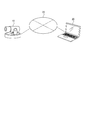
- FIG. 2 is a diagram showing an example of a system configuration including the monitoring camera 10.
- the monitoring camera 10 and the client device 20 are connected in a mutually communicable state via the network 35.
- the client device 20 is an external device that transmits control commands such as a profile tying setting command and a profile acquisition command to the monitoring camera 10.
- the monitoring camera 10 transmits a response to the command to the client device 20.
- the dewarping information is information related to the dewarping process.
- a fish-eye image captured through a fish-eye lens is often subjected to processing of both image cutting and distortion correction called dewarping.
- the clipped image is called in various ways depending on the clip position, the number of clips, and the possibility of changing the clip position.
- the cutting range is wide, it may be called a panorama.
- the cutting out four images whose cutting positions can be changed from a fish-eye image it may be called a four-screen mode or a four-frame cutting mode.
- two panoramic images are cut out, it is sometimes called double panoramic mode.
- distortion correction processing in the dewarping processing is processing for adjusting distortion and inclination caused by a fisheye lens, and converting the image into an image in almost the same state as a human being visually recognizes.
- de-warping processing performing at least the above-described correction processing is referred to as de-warping processing, and information related thereto is referred to as de-warping information. That is, information indicating whether or not the dewarping process has been performed (or whether or not the dewarping process should be performed), information indicating the type of the dewarping process (its name), and the like are referred to as dewarping information.
- the dewarp information may simply indicate the name (fisheye, cutout, panorama, etc.) of each video stream related to the fisheye image, or may be an index indicating the name. It may be any information that indicates what kind of video stream is to be transmitted and received based on a fisheye image between at least the surveillance camera and the client device.
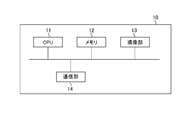
- FIG. 3A is a diagram showing an example of a hardware configuration of the monitoring camera 10. As shown in FIG.
- the CPU 11 controls the entire surveillance camera 10.
- the memory 12 is used as a storage area for various data.
- a storage area there are a program storage area executed by the CPU 11, a work area during program execution, and the like.
- a setting value storage area such as a setting value (configuration) of the monitoring camera, a profile, a correlating setting between the profile and the dewarp information, and an installation situation of the camera such as ceiling attachment or wall attachment.
- storage areas there are a dependency relation table between configurations, information storage areas such as pan / tilt / zoom support information for each dewarp information, storage areas of image data generated by the imaging unit 13 described later, and the like.
- dewarp information for determining distortion correction of the image and the presence or absence of the clipping range
- a video source configuration (Video Source Configuration) including the resolution that the sensor can output.
- video encoder setting (Video Encoder Configuration) including an encoding type and resolution of image encoding, and the like.
- PTZ setting PTZ Configuration
- the configuration is mapped (correlated) to a profile (Profile) specified for control of the surveillance camera, and the surveillance camera performs video distribution, PTZ control, etc. with the contents of the configuration mapped to the profile.
- Profile profile
- the imaging unit 13 captures an image of a subject formed by the imaging optical system of the monitoring camera 10, converts the acquired analog signal into digital data, and outputs the digital data to the memory 12 as a captured image.
- the CPU 11 receives an image acquisition event from the imaging unit 13.
- the communication unit 14 is used when receiving each control command such as profile acquisition from an external device, and when transmitting a response to each control command to the external device.
- the CPU 11 receives a command reception event from the communication unit 14.
- the hardware configuration of the surveillance camera 10 shown in FIG. 3A is an example, and in addition to the one shown in FIG. 3A, the surveillance camera 10 includes an audio input unit, an audio output unit, an image analysis processing unit, etc. You may have as.
- FIG. 3B is a diagram showing an example of the hardware configuration of the client device 20. As shown in FIG.
- the CPU 21 controls the entire client device 20.
- the memory 22 is mainly used as a storage area for various data, such as a program storage area executed by the CPU 21 and a work area during program execution.
- the display unit 23 is configured of, for example, an LCD, an organic EL display, or the like.
- the display unit 23 displays various setting screens and display screens including a setting screen for linking the profile and the warp information to the user of the client device 20, a viewer of the video received from the monitoring camera 10, various messages, and the like.
- the input unit 24 includes, for example, a button, an arrow key, a touch panel, and a mouse, and notifies the CPU 21 of the content of the screen operation by the user.
- the communication unit 25 is used for transmitting a response to each control command or receiving a video stream from the monitoring camera 10 when transmitting each control command including a profile tying setting command and profile acquisition to the monitoring camera 10. Ru.
- FIG. 4A is a view showing an example of the software configuration of the monitoring camera 10. As shown in FIG.
- the control unit 100 controls the entire processing of the surveillance camera 10.
- the imaging control unit 101 controls the imaging unit 13.
- the imaging control unit 101 changes the imaging range of the imaging unit 13 to tilt drive, pan drive, or zoom drive according to the pan, tilt, or zoom value input by the control unit 100.
- the compression encoding unit 102 applies JPEG or H.264 to the captured image output from the imaging unit 13.
- Image data is generated by performing compression encoding processing based on the format such as H.265 and output to the memory 12.
- the imaging control unit 101 may be mounted on the monitoring camera 10 as a hardware configuration.
- the compression encoding unit 102 may also be mounted on the monitoring camera 10 as a hardware configuration.
- FIG. 4B is a diagram showing an example of the software configuration of the client device 20. As shown in FIG.
- the control unit 200 controls the entire processing of the client device 20.
- the decoding unit 201 performs JPEG or H.264 compression-encoded image data received via the communication unit 25. H.264. Decoding is performed based on the format such as 265 and expanded in the memory 22.
- the decryption unit 201 may be implemented in the client device 20 as a hardware configuration.
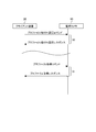
- FIG. 5 is a sequence diagram of processing relating to a profile tying setting command and a profile acquisition command of the monitoring camera 10.
- the control unit 200 of the client device 20 transmits a profile tying setting command including tying information between the profile and the dewarp information.
- the control unit 100 of the monitoring camera 10 receives a profile tying setting command, performs profile tying setting command processing 30, and transmits a profile tying setting response to the client device 20 as a response.
- the control unit 200 of the client device 20 receives the profile tying setting response.
- the profile is a setting information group including a plurality of setting information as shown in FIG.
- the linking information is an example of information indicating the association between the profile and the dewarp information.
- the control unit 200 of the client device 20 transmits a profile acquisition command.
- the control unit 100 of the monitoring camera 10 receives the profile acquisition command, performs profile acquisition command processing 31, and transmits a profile acquisition response to the client device 20 as a response.
- the control unit 200 of the client device 20 receives the profile acquisition response.
- the profile association setting command and the profile acquisition command are transmitted from the same client device 20, different commands may be transmitted from different client devices 20.
- the protocol of each command is not limited, and the protocol of the command is ONVIF, a control protocol unique to the surveillance camera, or the like.
- the profile tying setting command processing 30 and the profile acquisition command processing 31 are examples of information processing.
- FIG. 6 is a setting screen for correlating the profile and the dewarp information.
- the setting screen of FIG. 6 is displayed on the display unit 23 of the client device 20.
- a list of identifier IDs of profiles set in the monitoring camera 10 is displayed.
- the user operates the input unit 24 of the client device 20 and selects the dewarp information to be associated with the profile from the dewarp information selection box 42.
- the control unit 200 of the client device 20 transmits a profile tying setting command to the monitoring camera 10.
- Data for displaying the setting screen shown in FIG. 6 may be included in the client device 20, or may be included in the monitoring camera 10, and in response to a request from the client device 20, the web browser of the client device 20 It may be displayed on the like.
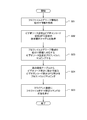
- FIG. 7 is a flowchart showing an example of the profile tying setting command processing 30.
- step S51 the control unit 100 stores, in the memory 12, the profile connection information (the connection information between the profile and the dewarp information) specified by the profile connection setting command, and the process proceeds to step S52.
- control unit 100 acquires the video source setting, the video encoder setting, and the PTZ setting dependency relationship table 60 from the memory 12, and transitions to S53.
- FIG. 8 is a diagram showing an example of a dependency relationship table between configurations that can be mapped to a profile.
- the video encoder setting that can be mapped to the profile together with the video source setting 1 is the video encoder setting 1 and there is no PTZ setting.
- a video encoder setting that can be mapped to a profile together with the video source setting 2 is a video encoder setting 2 and a PTZ setting is a PTZ setting 1.
- control unit 100 acquires the association information between the profile and the dewarp information from the memory 12, maps the video source setting corresponding to the dewarp information to the profile, and shifts to S54.
- the process of S53 is an example of a process of acquiring tying information between the profile and the dewarp information.
- the control unit 100 maps the video encoding setting and the PTZ setting corresponding to the mapped video source setting to the profile with the contents of the dependency relationship table.
- the processes of S53 and S54 are an example of an associating process of associating the video source setting, the video encoding setting, and the PTZ setting with the profile based on the association information.
- the process of S54 is an example of the process of mapping to the video encoding setting that can be set to the mapped video source setting, the PTZ setting, and the profile based on the dependency relationship table.
- control unit 100 generates a response to the profile tying setting command, and transmits a response to the profile tying setting command to the client device 20.
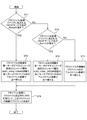
- FIG. 9 is a flowchart showing an example of the profile acquisition command process 31.
- step S71 the control unit 100 acquires the ONVIF service name included in the profile setting command, and the ONVIF service name is JPEG as video encoding. It is determined whether or not it is a Meida service that supports H.264. The control unit 100 determines that the ONVIF service name is JPEG as video encoding and H.264. If the service is a Meida service that supports H.264, the process transitions to step S72; otherwise, the process transitions to step S73.
- the control unit 100 rearranges the order of the profiles returned as a response to the profile acquisition command. First, the control unit 100 determines that the encoding type of the video encoder setting included in the profile is H.264. H.264, JPEG, H. Sort the profiles in the order of 265. Then, the control unit 100 further rearranges profiles of the same encoding type in ascending order of profile ID in alphabetical order, and shifts to S76.
- the control unit 100 acquires the ONVIF service name included in the profile setting command, and the ONVIF service name is JPEG as video encoding. H.264. It is determined whether or not it is a Media2 service that supports H.265. The control unit 100 determines that the ONVIF service name is JPEG as video encoding and H.264. H.264. If it is a Media2 service that supports H.265, the process goes to S74; otherwise, it goes to S75.
- the control unit 100 rearranges the order of the profiles returned as a response to the profile acquisition command.
- the control unit 100 determines that the encoding type of the video encoder setting included in the profile is H.264. H.265. Sort the profiles in the order of H.264 and JPEG. After that, the control unit 100 further rearranges profiles of the same encoding type in ascending order of profile ID alphabetically, and transitions to S76.
- control unit 100 rearranges the order of the profiles returned as a response to the profile acquisition command.
- the control unit 100 rearranges the profiles in ascending order of profile ID alphabetically, and transitions to S76.
- control unit 100 creates a response of the profile acquisition command using the rearranged profile, and transmits the response of the profile acquisition command to the client device 20.
- FIG. 9 shows an example of control for determining the order of responding profiles according to the service name included in the profile acquisition command
- the order of responding profiles is determined according to the version information instead of the service name. Control may be performed.
- the process in FIG. 9 is an example of a process of controlling to finally transmit to the client device 20 a profile including a video encoder setting in which an unsupported encoding type is set according to the service name included in the profile acquisition command. It is.
- the user does not have to consider the dependency between the video source setting, the video encoder setting, and the PTZ setting in the first embodiment.
- Video source settings, video encoder settings, and PTZ settings adapted to the dewarp information linked to the profile by the user can be mapped to the profile based on the dependency relationship table between the monitoring camera 10 between configurations. Therefore, appropriate video distribution and PTZ control can be performed.
- the profile returned by the profile acquisition command can be preferentially returned by a profile that can be handled by the client device 20.
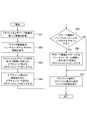
- control unit 100 stores the profile tying information specified in the profile tying setting command in the memory 12, and transitions to S82.
- control unit 100 acquires pan / tilt / zoom support information indicating whether pan / tilt / zoom is possible for each dewarp information from the memory 12, and transitions to S83.
- control unit 100 maps the video source setting corresponding to the dewarp information from the memory 12 to the profile, and transitions to S84.
- step S84 the control unit 100 maps a video encoding setting having a resolution that includes the resolution that can be output by the sensor in the video source setting to the profile, and the process transitions to step S85.
- step S85 the control unit 100 determines whether the dewarp information supports pan, tilt, or zoom from the pan, tilt, or zoom support information.
- the control unit 100 transitions to S86 when the dewarp information supports any of pan, tilt, and zoom, and transitions to S87 when neither is supported.
- step S86 the control unit 100 maps the PTZ setting that matches the pan, tilt, and zoom support information on the profile, and the process transitions to step S87.
- control unit 100 In S87, the control unit 100 generates a response to the profile tying setting command, and transmits a response to the profile tying setting command to the client device 20.
- the user does not have to consider the dependency between the video source setting, the video encoder setting, and the PTZ setting.
- the surveillance camera 10 can map video source settings, video encoder settings, and PTZ settings that match from the resolution of the video source settings and the video encoder settings and the pan-tilt-zoom support information to the profile. Therefore, appropriate video distribution and PTZ control can be performed.
- the profile returned by the profile acquisition command can be preferentially returned by a profile that can be handled by the client device 20.
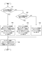
- control unit 100 acquires the installation state of the camera from the memory 12 and determines whether or not the ceiling is attached. The control unit 100 transitions to S92 if the ceiling is attached, and transitions to S93 otherwise.
- the control unit 100 rearranges the order of the profiles returned as a response to the profile acquisition command.
- the dewarping information of the video source setting included in the profile is a fisheye (without dewarping processing), cutout 1 (with dewarping processing capable of changing the cutout position two-dimensionally), panorama (with dewarping processing)
- the profiles of the same dewarp information are further sorted in the ascending order of profile ID alphabetically after the profiles are rearranged in the order of two-dimensional cutout position change), and the process proceeds to S96.
- control unit 100 acquires the installation state of the camera from the memory 12 and determines whether or not the wall is attached. If the control unit 100 is wall-mounted, the process transitions to step S94. Otherwise, the control unit 100 transitions to step S95.
- the control unit 100 rearranges the order of the profiles returned as a response to the profile acquisition command. First, after the control unit 100 rearranges the profiles in the order of panorama, cutout 1, and fisheye in the video source setting dewarp information included in the profile, the profiles of the same dewarp information are further rearranged in ascending order of profile ID in alphabetical order. , S96.
- step S95 the control unit 100 rearranges the order of profiles returned as a response to the profile acquisition command.
- the control unit 100 rearranges the profile IDs in ascending alphabetical order, and transitions to S96.
- control unit 100 creates a response of the profile acquisition command using the rearranged profile, and transmits the response of the profile acquisition command to the client device 20.
- the user does not have to consider the dependency between the video source setting, the video encoder setting, and the PTZ setting.
- Video source settings, video encoder settings, and PTZ settings adapted to the dewarp information linked to the profile by the user can be mapped to the profile based on the dependency relationship table between the monitoring camera 10 between configurations. Therefore, appropriate video distribution and PTZ control can be performed.
- the profile returned by the profile acquisition command can be preferentially returned in the profile assumed to be used in the installation state of the surveillance camera such as ceiling attachment or wall attachment.
- the present invention supplies a program that implements one or more functions of the above-described embodiments to a system or apparatus via a network or a storage medium. And, it is also possible to realize the processing in which one or more processors in the computer of the system or apparatus read and execute the program. It can also be implemented by a circuit (eg, an ASIC) that implements one or more functions.
- a circuit eg, an ASIC
- the hardware configuration of the monitoring camera 10 described above is an example, and for example, a plurality of CPUs, memories, communication units, and the like may be provided. Also, a plurality of CPUs may execute processing based on programs and using data stored in a plurality of memories. Alternatively, a GPU (Graphics Processing Unit) may be used instead of the CPU.
- a GPU Graphics Processing Unit
Abstract
複数の設定情報を含む設定情報群であるプロファイルと、魚眼画像に係るデワープ情報との関連を示す紐付け情報を取得する取得手段と、取得手段により取得された紐付け情報に基づいてビデオソース設定とビデオエンコード設定とPTZ設定とをプロファイルに対応付ける対応付け手段と、を有する。
Description
本発明は、撮像装置、情報処理方法及びプログラムに関する。
従来、クライアント装置へ撮像画像を送信する監視カメラにおいて、外部装置から監視カメラの設定変更や、画像の配信の開始を指示するコマンド群が実装されている。そのようなコマンド群の例として、ONVIF(Open Network Video Interface Forum)により策定された規格によって定義されるものが知られている。
ONVIFでは監視カメラの設定(コンフィグレーション)として、以下のものが設定されている。即ち、画像の歪み補正、切り出し範囲の有無や種類を決定するデワープ情報やセンサーが出力可能な解像度を含むビデオソース設定(Video Source Configuration)が定義されている。また、画像の符号化のエンコード種別や解像度等を含むビデオエンコーダ設定(Video Encoder Configuration)が定義されている。また、パン・チルト・ズームをサポートする・しない等を含むPTZ設定(PTZ Configuration)等が定義されている。
これらのコンフィグレーションは監視カメラの制御に指定するプロファイル(Profile)にマッピング(関連付け)され、監視カメラは、そのプロファイルにマッピングされたコンフィグレーションの内容で映像配信やPTZ制御等を行う。プロファイルとは、上記の各設定の集合であり、例えば、クライアント装置が、監視カメラから映像ストリームを受信する際に使う。例えば、クライアント装置は、プロファイルに含まれる各設定を指定し、その各設定に基づく映像ストリームを送信するよう、監視カメラに指示する。図1は、ONVIFでコンフィグレーションをプロファイルにマッピングする一例を示す図である。このように1つ以上のビデオソース設定、ビデオエンコーダ設定、PTZ設定からそれぞれ1つを選択し、プロファイルにマッピングする。
監視カメラが各コンフィグレーションをマッピング済みのプロファイルを準備するか、クライアント装置が監視カメラから各コンフィグレーションを取得し、そのコンフィグレーションをプロファイルにマッピングする方法がある。クライアント装置でプロファイルにマッピングする場合は、各コンフィグレーション間の依存関係を考慮してマッピングする必要がある。
例えば、全方位カメラで魚眼、パノラマ画像、魚眼からの一部切り出し画像等、複数の画像を生成できるカメラの場合、画像のデワープ情報はビデオソース設定で指定する。
監視カメラから魚眼画像を配信する場合には、魚眼画像に対応したビデオソース設定をプロファイルにマッピングするが、その際に魚眼画像で設定可能な解像度を持つビデオエンコーダ設定を設定する必要がある。
また、魚眼画像でPTZできない場合は、PTZ設定はプロファイルにマッピングできない。
このように配信する画像のデワープ情報によって、それに対応したビデオソース設定、ビデオエンコーダ設定、PTZ設定をプロファイルにマッピングする必要があり、正しくマッピングしないと監視カメラは映像配信、PTZ制御が行えない。
また、特開2014-107590号公報には、ビデオソース設定とビデオエンコーダ設定との設定値間を調整する撮像装置が開示されている。
しかし、特開2014-107590号公報の技術では監視カメラの各コンフィグレーション間の設定値の依存関係を調整するものである。
監視カメラの各コンフィグレーション間の設定値の依存関係を調整するために、例えば、以下の構成を有する。複数の設定情報を含む設定情報群であるプロファイルと、魚眼画像に係るデワープ情報との関連を示す紐付け情報を取得する取得手段と、前記取得手段により取得された前記紐付け情報に基づいてビデオソース設定とビデオエンコード設定とPTZ設定とをプロファイルに対応付ける対応付け手段と、を有する。
以下、本発明の実施形態について図面に基づいて説明する。
<実施形態1>
図2は、監視カメラ10を含むシステム構成の一例を示す図である。監視カメラ10とクライアント装置20とは、ネットワーク35を介して相互に通信可能な状態に接続されている。クライアント装置20は、監視カメラ10に対して、プロファイル紐付け設定コマンドやプロファイル取得コマンド等の各制御コマンドを送信する外部装置である。監視カメラ10は、コマンドに対するレスポンスをクライアント装置20に送信する。
図2は、監視カメラ10を含むシステム構成の一例を示す図である。監視カメラ10とクライアント装置20とは、ネットワーク35を介して相互に通信可能な状態に接続されている。クライアント装置20は、監視カメラ10に対して、プロファイル紐付け設定コマンドやプロファイル取得コマンド等の各制御コマンドを送信する外部装置である。監視カメラ10は、コマンドに対するレスポンスをクライアント装置20に送信する。
以下の説明において、デワープ情報とは、デワープ処理に関する情報である。例えば、魚眼レンズを介して撮影された魚眼画像に対して、デワープ処理と呼ばれる、画像の切出しと歪み補正の両方の処理が行われることが多い。切出された画像は、その切出し位置や、切出す数、切出し位置の変更が可能かによって、様々な呼ばれ方をする。例えば、切出し範囲が広い場合はパノラマと呼ばれることがある。また、魚眼画像から、切出し位置を変更可能な4つの画像を切出す場合は、4画面モードや4画切出しモードと呼ばれることがある。2つのパノラマ映像を切出す場合はダブルパノラマモードと呼ばれることがある。また、デワープ処理における歪み補正処理は魚眼レンズに起因する歪みや傾きを調整し、人が視認している状態とほぼ同じ状態の画像に変換する処理である。
各実施形態では少なくとも上記の補正処理を行うことをデワープ処理と称し、それに関する情報をデワープ情報と称することとする。つまり、デワープ処理を行ったか否か(又はデワープ処理をすべきか否か)を示す情報や、どのようなデワープ処理を行ったかを示す情報(その名称)等をデワープ情報と称することとする。デワープ情報は、単に魚眼画像に係る各映像ストリームの名称(魚眼、切出し、パノラマ等)を示すものであったり、その名称を示すインデックスであったりしてもよい。少なくとも監視カメラと、クライアント装置との間で、魚眼画像に基づくどのような映像ストリームが送受信されるかが分かる情報であればよい。
図3Aは、監視カメラ10のハードウェア構成の一例を示す図である。
CPU11は、監視カメラ10の全体の制御を行う。
メモリ12は、様々なデータの格納領域として使用される。格納領域としては、CPU11が実行するプログラム格納領域、プログラム実行中のワーク領域等がある。また、格納領域としては、監視カメラの設定値(コンフィグレーション)、プロファイル、プロファイルとデワープ情報との紐付け設定、天井付けや壁付け等のカメラの設置状況等の設定値格納領域がある。
また、格納領域としては、コンフィグレーション間の依存関係テーブル、デワープ情報ごとのパン・チルト・ズームサポート情報等の情報格納領域、後述する撮像部13が生成する画像データの格納領域等がある。また、コンフィグレーションとして、画像の歪み補正と切り出し範囲の有無や種類を決定するデワープ情報やセンサーが出力可能な解像度を含むビデオソース設定(Video Source Configuration)等がある。また、コンフィグレーションとして、画像の符号化のエンコード種別や解像度等を含むビデオエンコーダ設定(Video Encoder Configuration)等がある。また、コンフィグレーションとして、パン・チルト・ズームをサポートする・しない等を含むPTZ設定(PTZ Configuration)等がある。また、コンフィグレーションは監視カメラの制御に指定するプロファイル(Profile)にマッピング(対応付け)され、監視カメラはそのプロファイルにマッピングされたコンフィグレーションの内容で映像配信やPTZ制御等を行う。
撮像部13は、監視カメラ10の撮像光学系により結像された被写体の像を撮像して取得したアナログ信号をデジタルデータに変換し、撮像画像としてメモリ12に出力する。撮像画像がメモリ12に出力されたとき、CPU11は撮像部13から画像取得イベントを受信する。
通信部14は、プロファイル取得等の各制御コマンドを外部機器から受信する場合、また各制御コマンドに対するレスポンスを外部機器へ送信する場合に使用される。外部機器からコマンドを受信した場合、CPU11は通信部14からコマンド受信イベントを受信する。
CPU11がメモリ12に記憶されたプログラムに基づき処理を実行することによって、後述する図4Aのソフトウェア構成及び図5のシーケンス図の監視カメラ10の処理、図7~図11のフローチャートの処理が実現される。
ここで、図3Aに示した監視カメラ10のハードウェア構成は一例であり、図3Aに示したもの以外に、監視カメラ10は、音声入力部、音声出力部、画像解析処理部等をハードウェアとして有していてもよい。
図3Bは、クライアント装置20のハードウェア構成の一例を示す図である。
CPU21は、クライアント装置20の全体の制御を行う。
メモリ22は、主にCPU21が実行するプログラム格納領域、プログラム実行中のワーク領域等、様々なデータの格納領域として使用される。
表示部23は、例えばLCD、有機ELディスプレイ等で構成される。表示部23は、クライアント装置20の使用者に対して、プロファイルとデワープ情報との紐付けを行う設定画面を含む様々な設定画面や表示画面、監視カメラ10から受信する映像のビューワ、各種メッセージ等を表示する。
入力部24は、例えばボタン、十字キー、タッチパネル、マウス等で構成され、使用者による画面操作の内容をCPU21に通知する。
通信部25は、プロファイル紐付け設定コマンドやプロファイル取得を含む各制御コマンドを監視カメラ10に対して送信する場合、各制御コマンドに対するレスポンスや、映像ストリームを監視カメラ10から受信する場合等に使用される。
CPU21がメモリ22に記憶されたプログラムに基づき処理を実行することによって、後述する図4Bのソフトウェア構成及び図5のシーケンス図のクライアント装置20の処理が実現される。
図4Aは、監視カメラ10のソフトウェア構成の一例を示す図である。
制御部100は、監視カメラ10の全体の処理を制御する。
撮像制御部101は、撮像部13を制御する。例えば、撮像制御部101は、制御部100が入力するパン、チルト、或いはズームの値に従って、撮像部13の撮像範囲をチルト駆動、パン駆動、或いはズーム駆動に変更させる。
圧縮符号化部102は、撮像部13が出力した撮像画像に対してJPEG或いはH.264、H.265等の形式に基づき圧縮符号化処理を行うことにより画像データを生成し、メモリ12に出力する。
撮像制御部101は、ハードウェア構成として監視カメラ10に実装されていてもよい。同様に、圧縮符号化部102も、ハードウェア構成として監視カメラ10に実装されていてもよい。
図4Bは、クライアント装置20のソフトウェア構成の一例を示す図である。
制御部200は、クライアント装置20の全体の処理を制御する。
復号部201は、通信部25を介して受信された圧縮符号化されている画像データをJPEG、或いはH.264、H.265等の形式に基づいて復号化し、メモリ22に展開する。
復号部201は、ハードウェア構成としてクライアント装置20に実装してもよい。
図5は、監視カメラ10のプロファイル紐付け設定コマンドとプロファイル取得コマンドとに係る処理のシーケンス図である。
クライアント装置20の制御部200は、プロファイルとデワープ情報との紐付け情報を含むプロファイル紐付け設定コマンドを送信する。監視カメラ10の制御部100は、プロファイル紐付け設定コマンドを受信し、プロファイル紐付け設定コマンド処理30を行い、その応答としてプロファイル紐付け設定レスポンスをクライアント装置20に送信する。クライアント装置20の制御部200は、プロファイル紐付け設定レスポンスを受信する。プロファイルは、図1等に示されるように、複数の設定情報を含む設定情報群である。また、紐付け情報は、プロファイルとデワープ情報との関連を示す情報の一例である。
クライアント装置20の制御部200は、プロファイル取得コマンドを送信する。監視カメラ10の制御部100は、プロファイル取得コマンドを受信し、プロファイル取得コマンド処理31を行い、その応答としてプロファイル取得レスポンスをクライアント装置20に送信する。クライアント装置20の制御部200は、プロファイル取得レスポンスを受信する。
図5では同一のクライアント装置20からプロファイル紐付け設定コマンドとプロファイル取得コマンドとを送信しているが、異なるクライアント装置20から各コマンドを送信してもよい。また、各コマンドのプロトコルを制限するものではなく、コマンドのプロトコルはONVIFや監視カメラ独自の制御プロトコル等である。
プロファイル紐付け設定コマンド処理30、プロファイル取得コマンド処理31は、情報処理の一例である。
図6は、プロファイルとデワープ情報との紐付けを行う設定画面である。図6の設定画面は、クライアント装置20の表示部23に表示される。プロファイルID一覧表示エリア41には監視カメラ10に設定されているプロファイルの識別子IDの一覧が表示される。ユーザはクライアント装置20の入力部24を操作し、デワープ情報選択ボックス42からプロファイルに紐付けるデワープ情報を選択する。ユーザが紐付け設定43を選択すると、クライアント装置20の制御部200は、プロファイル紐付け設定コマンドを監視カメラ10に送信する。
図6の設定画面を表示するためのデータは、クライアント装置20が有していてもよいし、監視カメラ10が有しており、クライアント装置20からの要求に応じて、クライアント装置20のWebブラウザ等に表示されるようにしてもよい。
図7は、プロファイル紐付け設定コマンド処理30の一例を示すフローチャートである。
S51で、制御部100は、プロファイル紐付け設定コマンドにより指定されたプロファイル紐付け情報(プロファイルとデワープ情報との紐付け情報)をメモリ12に格納し、S52に遷移する。
S52で、制御部100は、メモリ12から、ビデオソース設定、ビデオエンコーダ設定、PTZ設定の依存関係テーブル60を取得し、S53に遷移する。
図8は、プロファイルにマッピング可能なコンフィグレーション間の依存関係テーブルの一例を示す図である。ビデオソース設定1と一緒にプロファイルにマッピング可能なビデオエンコーダ設定はビデオエンコーダ設定1で、PTZ設定はない。また、ビデオソース設定2と一緒にプロファイルにマッピング可能なビデオエンコーダ設定はビデオエンコーダ設定2で、PTZ設定はPTZ設定1である。
S53で、制御部100は、メモリ12から、プロファイルとデワープ情報との紐付け情報を取得し、デワープ情報に対応するビデオソース設定をプロファイルにマッピングし、S54に遷移する。S53の処理は、プロファイルとデワープ情報との紐付け情報を取得する処理の一例である。
S54で、制御部100は、依存関係テーブルの内容で、マッピングしたビデオソース設定に対応するビデオエンコード設定とPTZ設定とをプロファイルにマッピングする。S53及びS54の処理は、紐付け情報に基づいてビデオソース設定とビデオエンコード設定とPTZ設定とをプロファイルに対応付ける対応付け処理の一例である。また、S54の処理は、依存関係テーブルに基づき、マッピングしたビデオソース設定に設定可能なビデオエンコード設定とPTZ設定とプロファイルにマッピングする処理の一例である。
S55で、制御部100は、プロファイル紐付け設定コマンドの応答を生成し、クライアント装置20にプロファイル紐付け設定コマンドの応答を送信する。
図9は、プロファイル取得コマンド処理31の一例を示すフローチャートである。
S71で、制御部100は、プロファイル設定コマンドに含まれるONVIFサービス名を取得し、ONVIFサービス名がビデオエンコーディングとしてJPEG、H.264をサポートするMeidaサービスであるか否かを判定する。制御部100は、ONVIFサービス名がビデオエンコーディングとしてJPEG、H.264をサポートするMeidaサービスである場合、S72に遷移し、それ以外の場合はS73に遷移する。
S72で、制御部100は、プロファイル取得コマンドの応答として返すプロファイルの順番を並べ替える。まず、制御部100は、プロファイルに含まれるビデオエンコーダ設定のエンコード種別がH.264、JPEG、H.265の順番でプロファイルを並べ替える。そして、制御部100は、同じエンコード種別のプロファイルは更にプロファイルIDのアルファベット昇順で並べ替え、S76に遷移する。
S73で、制御部100は、プロファイル設定コマンドに含まれるONVIFサービス名を取得し、ONVIFサービス名がビデオエンコーディングとしてJPEG、H.264、H.265をサポートするMedia2サービスであるか否かを判定する。制御部100は、ONVIFサービス名がビデオエンコーディングとしてJPEG、H.264、H.265をサポートするMedia2サービスであった場合、S74に遷移し、それ以外であった場合、S75に遷移する。
S74で、制御部100は、プロファイル取得コマンドの応答として返すプロファイルの順番を並べ替える。まず、制御部100は、プロファイルに含まれるビデオエンコーダ設定のエンコード種別がH.265、H.264、JPEGの順番でプロファイルを並べ替える。その後、制御部100は、同じエンコード種別のプロファイルは更にプロファイルIDのアルファベット昇順で並べ替え、S76に遷移する。
S75で、制御部100は、プロファイル取得コマンドの応答として返すプロファイルの順番を並べ替える。制御部100は、プロファイルIDのアルファベット昇順でプロファイルを並べ替え、S76に遷移する。
S76で、制御部100は、プロファイル取得コマンドの応答を並べ替えたプロファイルで作成し、クライアント装置20にプロファイル取得コマンドの応答を送信する。
図9では、プロファイル取得コマンドに含まれるサービス名に応じて、応答するプロファイルの順番を決定する制御の一例を示したが、サービス名の替わりにバージョン情報に応じて、応答するプロファイルの順番を決定する制御をするようにしてもよい。
図9の処理は、プロファイル取得コマンドに含まれるサービス名に応じて、サポートされていないエンコード種別が設定されているビデオエンコーダ設定を含むプロファイルを最後にクライアント装置20に送信するよう制御する処理の一例である。
以上、説明したように、実施形態1では、ユーザはビデオソース設定、ビデオエンコーダ設定、PTZ設定間の依存関係を考慮する必要がない。監視カメラ10がコンフィグレーション間の依存関係テーブルを基に、ユーザがプロファイルに紐付けたデワープ情報に適合したビデオソース設定、ビデオエンコーダ設定、PTZ設定をプロファイルにマッピングすることができる。そのため、適切な映像配信、PTZ制御を行うことができる。
また、プロファイル取得コマンドで返すプロファイルを、クライアント装置20が扱うことが可能なプロファイルで優先的に返すことができる。
<実施形態2>
以下、図10を参照して、実施形態2に係る監視カメラ10のプロファイル紐付け設定コマンド受信時のプロファイル紐付け設定コマンド処理30について説明する。実施形態1と同じ部分については説明を省略する。
以下、図10を参照して、実施形態2に係る監視カメラ10のプロファイル紐付け設定コマンド受信時のプロファイル紐付け設定コマンド処理30について説明する。実施形態1と同じ部分については説明を省略する。
S81で、制御部100は、プロファイル紐付け設定コマンドに指定されたプロファイル紐付け情報をメモリ12に格納し、S82に遷移する。
S82で、制御部100は、メモリ12から、デワープ情報毎のパン・チルト・ズーム可能かを表すパン・チルト・ズームサポート情報を取得し、S83に遷移する。
S83で、制御部100は、メモリ12から、デワープ情報に対応するビデオソース設定をプロファイルにマッピングし、S84に遷移する。
S84で、制御部100は、ビデオソース設定のセンサーが出力可能な解像度を含む解像度を持つビデオエンコード設定をプロファイルにマッピングし、S85に遷移する。
S85で、制御部100は、パン・チルト・ズームサポート情報からデワープ情報がパン・チルト・ズームの何れかをサポートするか否かを判定する。制御部100は、デワープ情報がパン・チルト・ズームの何れかをサポートする場合、S86に遷移し、何れもサポートしない場合、S87に遷移する。
S86で、制御部100は、パン・チルト・ズームサポート情報に一致するPTZ設定をプロファイルにマッピングし、S87に遷移する。
S87で、制御部100は、プロファイル紐付け設定コマンドの応答を生成し、クライアント装置20にプロファイル紐付け設定コマンドの応答を送信する。
以上、説明したように、実施形態2では、ユーザはビデオソース設定、ビデオエンコーダ設定、PTZ設定間の依存関係を考慮する必要がない。監視カメラ10がビデオソース設定及びビデオエンコーダ設定の解像度とパン・チルト・ズームサポート情報とから適合するビデオソース設定、ビデオエンコーダ設定、PTZ設定をプロファイルにマッピングすることができる。そのため、適切な映像配信、PTZ制御を行うことができる。
また、プロファイル取得コマンドで返すプロファイルを、クライアント装置20が扱うことが可能なプロファイルで優先的に返すことができる。
<実施形態3>
以下、図11を参照して、実施形態3に係る監視カメラ10のプロファイル取得コマンド受信時のプロファイル取得コマンド処理31について説明する。実施形態1と同じ部分については説明を省略する。
以下、図11を参照して、実施形態3に係る監視カメラ10のプロファイル取得コマンド受信時のプロファイル取得コマンド処理31について説明する。実施形態1と同じ部分については説明を省略する。
S91で、制御部100は、メモリ12からカメラの設置状態を取得し、天井付けであるか否かを判定する。制御部100は、天井付けであった場合、S92に遷移し、それ以外の場合は、S93に遷移する。
S92で、制御部100は、プロファイル取得コマンドの応答として返すプロファイルの順番を並べ替える。まず、制御部100は、プロファイルに含まれるビデオソース設定のデワープ情報が魚眼(デワープ処理無し)、切り出し1(デワープ処理ありで2次元的に切出し位置の変更が可能)、パノラマ(デワープ処理ありで、2次元的な切出し位置の変更は不可)の順番でプロファイルを並べ替えた後、同じデワープ情報のプロファイルは更にプロファイルIDのアルファベット昇順で並べ替え、S96に遷移する。
S93で、制御部100は、メモリ12からカメラの設置状態を取得し、壁付けであるか否かを判定する。制御部100は、壁付けであった場合、S94に遷移し、それ以外の場合は、S95に遷移する。
S94で、制御部100は、プロファイル取得コマンドの応答として返すプロファイルの順番を並べ替える。まず、制御部100は、プロファイルに含まれるビデオソース設定のデワープ情報がパノラマ、切り出し1、魚眼の順番でプロファイルを並べ替えた後、同じデワープ情報のプロファイルは更にプロファイルIDのアルファベット昇順で並べ替え、S96に遷移する。
S95で、制御部100は、プロファイル取得コマンドの応答として返すプロファイルの順番を並べ替える。制御部100は、プロファイルIDのアルファベット昇順で並べ替え、S96に遷移する。
S96で、制御部100は、プロファイル取得コマンドの応答を並べ替えたプロファイルで作成し、クライアント装置20にプロファイル取得コマンドの応答を送信する。
以上、説明したように、実施形態3では、ユーザはビデオソース設定、ビデオエンコーダ設定、PTZ設定間の依存関係を考慮する必要がない。監視カメラ10がコンフィグレーション間の依存関係テーブルを基に、ユーザがプロファイルに紐付けたデワープ情報に適合したビデオソース設定、ビデオエンコーダ設定、PTZ設定をプロファイルにマッピングすることができる。そのため、適切な映像配信、PTZ制御を行うことができる。
また、プロファイル取得コマンドで返すプロファイルを、天井付けや壁付け等の監視カメラの設置状態で使用されることが想定されるプロファイルで優先的に返すことができる。
<その他の実施形態>
本発明は、上述の実施形態の1以上の機能を実現するプログラムを、ネットワーク又は記憶媒体を介してシステム又は装置に供給する。そして、そのシステム又は装置のコンピュータにおける1つ以上のプロセッサーがプログラムを読み出し実行する処理でも実現可能である。また、1以上の機能を実現する回路(例えば、ASIC)によっても実現可能である。
本発明は、上述の実施形態の1以上の機能を実現するプログラムを、ネットワーク又は記憶媒体を介してシステム又は装置に供給する。そして、そのシステム又は装置のコンピュータにおける1つ以上のプロセッサーがプログラムを読み出し実行する処理でも実現可能である。また、1以上の機能を実現する回路(例えば、ASIC)によっても実現可能である。
以上、本発明の実施形態の一例について詳述したが、本発明は係る特定の実施形態に限定されるものではない。
上述した監視カメラ10のハードウェア構成は一例であり、例えば、CPUやメモリ、通信部等は複数有していてもよい。また、複数のCPUがプログラムに基づき、複数のメモリに記憶されたデータ等を用いながら処理を実行するようにしてもよい。また、CPUに替えてGPU(Graphics Processing Unit)を用いることとしてもよい。
また、上述した実施形態を任意に組み合わせて実施してもよい。
以上の各実施形態によれば、コンフィグレーションの組み合わせの依存関係を解決することができる。
本発明は上記実施の形態に制限されるものではなく、本発明の精神及び範囲から離脱することなく、様々な変更及び変形が可能である。従って、本発明の範囲を公にするために以下の請求項を添付する。
本願は、2017年8月1日提出の日本国特許出願特願2017-149095を基礎として優先権を主張するものであり、その記載内容の全てをここに援用する。
Claims (11)
- 複数の設定情報を含む設定情報群であるプロファイルと、魚眼画像に係るデワープ情報との関連を示す紐付け情報を取得する取得手段と、
前記取得手段により取得された前記紐付け情報に基づいてビデオソース設定とビデオエンコード設定とPTZ設定とをプロファイルに対応付ける対応付け手段と、
を有する撮像装置。 - 前記対応付け手段は、前記紐付け情報に対応する前記ビデオソース設定をプロファイルに対応付け、ビデオソース設定とビデオエンコード設定とPTZ設定との依存関係テーブルから前記プロファイルに対応付けられた前記ビデオソース設定に設定可能なビデオエンコード設定とPTZ設定とを前記プロファイルに対応付ける請求項1記載の撮像装置。
- 前記対応付け手段は、前記紐付け情報に対応する前記ビデオソース設定をプロファイルに対応付け、前記ビデオソース設定の解像度を含むビデオエンコード設定を前記プロファイルに対応付け、前記デワープ情報がサポートするパン、チルト、ズームに一致するPTZ設定を前記プロファイルに対応付ける請求項1記載の撮像装置。
- クライアント装置より受信された紐付け設定コマンドに含まれる前記紐付け情報をメモリに格納する格納手段を更に有し、
前記取得手段は、前記メモリより前記紐付け情報を取得する請求項1記載の撮像装置。 - クライアント装置より受信されたプロファイル取得コマンドに基づいて複数のプロファイルを前記クライアント装置に送信する場合、前記プロファイル取得コマンドに含まれるサービス名に応じて、応答するプロファイルの順番を決定する制御手段を更に有する請求項1記載の撮像装置。
- 前記制御手段は、前記プロファイル取得コマンドに含まれるサービス名に応じて、サポートされていないエンコード種別が設定されているビデオエンコーダ設定を含むプロファイルを最後に前記クライアント装置に送信するよう制御する請求項5記載の撮像装置。
- クライアント装置より受信されたプロファイル取得コマンドに基づいて複数のプロファイルを送信する場合、前記撮像装置の設置状態に応じて、応答するプロファイルの順番を決定する制御手段を更に有する請求項1記載の撮像装置。
- 前記デワープ情報は、デワープ処理の有無を示す情報を含む請求項1記載の撮像装置。
- 前記デワープ情報は、魚眼画像に係る情報であって、画像の種類を示す情報を含む請求項1記載の撮像装置。
- 撮像装置が実行する情報処理方法であって、
複数の設定情報を含む設定情報群であるプロファイルと、魚眼画像に係るデワープ情報との関連を示す紐付け情報を取得する取得工程と、
前記取得工程により取得された前記紐付け情報に基づいてビデオソース設定とビデオエンコード設定とPTZ設定とをプロファイルに対応付ける対応付け工程と、
を含む情報処理方法。 - コンピュータを、請求項1記載の撮像装置の各手段として機能させるためのプログラム。
Priority Applications (1)
| Application Number | Priority Date | Filing Date | Title |
|---|---|---|---|
| US16/775,009 US11010864B2 (en) | 2017-08-01 | 2020-01-28 | Image capturing apparatus, control method, and storage medium |
Applications Claiming Priority (2)
| Application Number | Priority Date | Filing Date | Title |
|---|---|---|---|
| JP2017-149095 | 2017-08-01 | ||
| JP2017149095A JP6968610B2 (ja) | 2017-08-01 | 2017-08-01 | 撮像装置、情報処理方法及びプログラム |
Related Child Applications (1)
| Application Number | Title | Priority Date | Filing Date |
|---|---|---|---|
| US16/775,009 Continuation US11010864B2 (en) | 2017-08-01 | 2020-01-28 | Image capturing apparatus, control method, and storage medium |
Publications (1)
| Publication Number | Publication Date |
|---|---|
| WO2019026666A1 true WO2019026666A1 (ja) | 2019-02-07 |
Family
ID=65232802
Family Applications (1)
| Application Number | Title | Priority Date | Filing Date |
|---|---|---|---|
| PCT/JP2018/027463 WO2019026666A1 (ja) | 2017-08-01 | 2018-07-23 | 撮像装置、情報処理方法及びプログラム |
Country Status (3)
| Country | Link |
|---|---|
| US (1) | US11010864B2 (ja) |
| JP (1) | JP6968610B2 (ja) |
| WO (1) | WO2019026666A1 (ja) |
Cited By (1)
| Publication number | Priority date | Publication date | Assignee | Title |
|---|---|---|---|---|
| CN112200875A (zh) * | 2020-12-02 | 2021-01-08 | 武汉光谷信息技术股份有限公司 | 非量测相机交叉耦合误差补偿与影像匹配纠正方法及系统 |
Families Citing this family (1)
| Publication number | Priority date | Publication date | Assignee | Title |
|---|---|---|---|---|
| JP7306857B2 (ja) * | 2019-04-05 | 2023-07-11 | 株式会社キーエンス | 画像検査システム |
Citations (5)
| Publication number | Priority date | Publication date | Assignee | Title |
|---|---|---|---|---|
| JP2013243544A (ja) * | 2012-05-21 | 2013-12-05 | Canon Inc | 撮像装置、マスク画像設定方法、および、プログラム |
| JP2013258538A (ja) * | 2012-06-12 | 2013-12-26 | Canon Inc | 撮像制御装置、撮像制御方法及びプログラム |
| JP2015080142A (ja) * | 2013-10-18 | 2015-04-23 | キヤノン株式会社 | 撮像装置、撮像システム、撮像装置の制御方法、撮像システムの制御方法、及びプログラム |
| JP2015222931A (ja) * | 2014-05-23 | 2015-12-10 | キヤノン株式会社 | 画像処理装置、及び外部装置 |
| JP2017017446A (ja) * | 2015-06-29 | 2017-01-19 | キヤノン株式会社 | 情報処理装置およびその制御方法、並びにプログラム |
Family Cites Families (52)
| Publication number | Priority date | Publication date | Assignee | Title |
|---|---|---|---|---|
| KR100327377B1 (ko) * | 2000-03-06 | 2002-03-06 | 구자홍 | 디지털 영상 수신기와 디지털 디스플레이 장치 사이에서디지털 영상 신호를 디스플레이 하는 방법 |
| US8479253B2 (en) * | 2007-12-17 | 2013-07-02 | Ati Technologies Ulc | Method, apparatus and machine-readable medium for video processing capability communication between a video source device and a video sink device |
| EP2232848A4 (en) * | 2007-12-20 | 2012-10-24 | Ati Technologies Ulc | ADJUSTING VIDEO PROCESSING IN A SYSTEM COMPRISING A VIDEO SOURCE DEVICE AND A VIDEO ACCUMULATION DEVICE |
| US10477158B2 (en) * | 2010-11-05 | 2019-11-12 | Razberi Technologies, Inc. | System and method for a security system |
| US11082665B2 (en) * | 2010-11-05 | 2021-08-03 | Razberi Secure Technologies, Llc | System and method for a security system |
| US9704393B2 (en) * | 2011-01-11 | 2017-07-11 | Videonetics Technology Private Limited | Integrated intelligent server based system and method/systems adapted to facilitate fail-safe integration and/or optimized utilization of various sensory inputs |
| EP2782329B1 (en) * | 2011-11-14 | 2019-10-16 | Canon Kabushiki Kaisha | Imaging device, control device, control method and program |
| US9066129B2 (en) * | 2012-04-24 | 2015-06-23 | Comcast Cable Communications, Llc | Video presentation device and method |
| JP5955171B2 (ja) * | 2012-09-11 | 2016-07-20 | キヤノン株式会社 | 送信装置、受信装置、送信方法、受信方法、及びプログラム |
| JP6204655B2 (ja) | 2012-11-22 | 2017-09-27 | キヤノン株式会社 | 撮像装置、撮像装置の制御方法、及びプログラム |
| JP6214178B2 (ja) * | 2013-01-25 | 2017-10-18 | キヤノン株式会社 | 撮像装置、クライアント装置、撮像システム、撮像装置の制御方法、クライアント装置の制御方法、および撮像システムの制御方法 |
| JP6103999B2 (ja) * | 2013-03-15 | 2017-03-29 | キヤノン株式会社 | 画像データ送信装置、画像データ受信装置、画像データ送信方法、画像データ受信方法、及びプログラム |
| JP6091269B2 (ja) * | 2013-03-15 | 2017-03-08 | キヤノン株式会社 | 撮像装置、クライアント装置、撮像システム、撮像装置の制御方法、クライアント装置の制御方法、および撮像システムの制御方法 |
| KR101321527B1 (ko) * | 2013-03-27 | 2013-10-28 | 조철휘 | 열교환기를 활용한 건조기 |
| JP6218471B2 (ja) * | 2013-07-20 | 2017-10-25 | キヤノン株式会社 | 撮像装置、外部装置、撮像システム、撮像装置の制御方法、外部装置の制御方法、撮像システムの制御方法、及びプログラム |
| JP6327816B2 (ja) * | 2013-09-13 | 2018-05-23 | キヤノン株式会社 | 送信装置、受信装置、送受信システム、送信装置の制御方法、受信装置の制御方法、送受信システムの制御方法、及びプログラム |
| JP6234165B2 (ja) * | 2013-10-28 | 2017-11-22 | キヤノン株式会社 | 撮像装置、外部装置、撮像システム、撮像装置の制御方法、外部装置の制御方法、撮像システムの制御方法、及びプログラム |
| JP2015088786A (ja) * | 2013-10-28 | 2015-05-07 | キヤノン株式会社 | 撮像装置、撮像システム、撮像装置の制御方法、撮像システムの制御方法、及びプログラム |
| JP6415037B2 (ja) * | 2013-11-12 | 2018-10-31 | キヤノン株式会社 | 撮像装置、クライアント装置、撮像装置の制御方法、クライアント装置の制御方法、及びプログラム |
| JP6338356B2 (ja) * | 2013-11-13 | 2018-06-06 | キヤノン株式会社 | 撮像装置、外部装置、撮像システム、撮像装置の制御方法、外部装置の制御方法、撮像システムの制御方法、及びプログラム |
| US9769369B2 (en) * | 2013-11-21 | 2017-09-19 | Canon Kabushiki Kaisha | Imaging apparatus, imaging system, control method of imaging apparatus, and storage medium |
| WO2015125420A1 (en) * | 2014-02-19 | 2015-08-27 | Canon Kabushiki Kaisha | Imaging apparatus and imaging system |
| JP6305110B2 (ja) * | 2014-02-28 | 2018-04-04 | キヤノン株式会社 | 撮像装置、及び撮像システム |
| JP6399766B2 (ja) * | 2014-03-07 | 2018-10-03 | キヤノン株式会社 | 撮像装置、撮像装置の制御方法及びプログラム |
| JP6230453B2 (ja) * | 2014-03-17 | 2017-11-15 | キヤノン株式会社 | 撮像装置及びその制御方法 |
| JP2015177467A (ja) * | 2014-03-17 | 2015-10-05 | キヤノン株式会社 | 撮像装置及びその制御方法 |
| JP6333019B2 (ja) * | 2014-03-28 | 2018-05-30 | キヤノン株式会社 | 撮像装置、撮像方法及びプログラム |
| JP2015220692A (ja) * | 2014-05-20 | 2015-12-07 | キヤノン株式会社 | 撮像装置、情報処理装置、撮像システム、及びそれらの制御方法、ならびにプログラム |
| JP6355428B2 (ja) * | 2014-05-21 | 2018-07-11 | キヤノン株式会社 | 撮像装置 |
| JP2015233208A (ja) * | 2014-06-09 | 2015-12-24 | キヤノン株式会社 | 画像処理装置 |
| JP6444073B2 (ja) * | 2014-06-25 | 2018-12-26 | キヤノン株式会社 | 画像処理装置 |
| TWI578781B (zh) * | 2014-10-21 | 2017-04-11 | 群暉科技股份有限公司 | 藉助於全景地圖來管理一監視系統之方法與裝置 |
| JP6381667B2 (ja) * | 2014-11-13 | 2018-08-29 | キヤノン株式会社 | 情報処理装置、制御方法、及び、プログラム |
| JP6566626B2 (ja) * | 2014-11-18 | 2019-08-28 | キヤノン株式会社 | 撮像装置 |
| JP6425569B2 (ja) * | 2015-01-30 | 2018-11-21 | キヤノン株式会社 | 通信装置 |
| JP6478777B2 (ja) * | 2015-04-13 | 2019-03-06 | キヤノン株式会社 | 制御装置及びその制御方法、プログラム |
| WO2016179303A1 (en) * | 2015-05-04 | 2016-11-10 | Kamama, Inc. | System and method of vehicle sensor management |
| JP6676347B2 (ja) * | 2015-11-09 | 2020-04-08 | キヤノン株式会社 | 制御装置、制御方法、及びプログラム |
| US9948983B2 (en) * | 2016-03-31 | 2018-04-17 | Rovi Guides, Inc. | Systems and methods for allowing access to a different version of the media asset |
| KR102474745B1 (ko) * | 2016-06-02 | 2022-12-05 | 한화테크윈 주식회사 | 모니터링 장치 및 모니터링 시스템 |
| GB2556925B (en) * | 2016-11-25 | 2020-07-29 | Canon Kk | Method and system for determining encoding parameters of video sources in large scale video surveillance systems |
| EP3549108A1 (en) * | 2016-12-02 | 2019-10-09 | Koninklijke KPN N.V. | Determining size of virtual object |
| US20190045109A1 (en) * | 2017-08-02 | 2019-02-07 | Canon Kabushiki Kaisha | Information processing apparatus, information processing method, and storage medium |
| JP6980450B2 (ja) * | 2017-08-09 | 2021-12-15 | キヤノン株式会社 | 制御装置、制御方法、及びプログラム |
| JP7073120B2 (ja) * | 2018-01-26 | 2022-05-23 | キヤノン株式会社 | 映像送信装置、情報処理装置、システム、情報処理方法及びプログラム |
| US10904423B2 (en) * | 2018-03-16 | 2021-01-26 | Hanwha Techwin Co., Ltd. | Image providing apparatus and method |
| JP7250440B2 (ja) * | 2018-05-31 | 2023-04-03 | キヤノン株式会社 | 撮影装置、情報処理装置、情報処理方法、およびプログラム |
| JP7065329B2 (ja) * | 2018-09-27 | 2022-05-12 | パナソニックIpマネジメント株式会社 | 窒化物半導体装置及びその製造方法 |
| US11496472B2 (en) * | 2018-11-16 | 2022-11-08 | Mutualink, Inc. | System and method for secure access to camera systems |
| JP7191663B2 (ja) * | 2018-12-04 | 2022-12-19 | キヤノン株式会社 | 撮像装置、制御方法及びプログラム |
| KR20200085556A (ko) * | 2019-01-07 | 2020-07-15 | 한화테크윈 주식회사 | 설정 장치 및 이의 제어 방법 |
| JP7204569B2 (ja) * | 2019-04-05 | 2023-01-16 | キヤノン株式会社 | 撮像装置、システム、撮像装置の制御方法、プログラム |
-
2017
- 2017-08-01 JP JP2017149095A patent/JP6968610B2/ja active Active
-
2018
- 2018-07-23 WO PCT/JP2018/027463 patent/WO2019026666A1/ja active Application Filing
-
2020
- 2020-01-28 US US16/775,009 patent/US11010864B2/en active Active
Patent Citations (5)
| Publication number | Priority date | Publication date | Assignee | Title |
|---|---|---|---|---|
| JP2013243544A (ja) * | 2012-05-21 | 2013-12-05 | Canon Inc | 撮像装置、マスク画像設定方法、および、プログラム |
| JP2013258538A (ja) * | 2012-06-12 | 2013-12-26 | Canon Inc | 撮像制御装置、撮像制御方法及びプログラム |
| JP2015080142A (ja) * | 2013-10-18 | 2015-04-23 | キヤノン株式会社 | 撮像装置、撮像システム、撮像装置の制御方法、撮像システムの制御方法、及びプログラム |
| JP2015222931A (ja) * | 2014-05-23 | 2015-12-10 | キヤノン株式会社 | 画像処理装置、及び外部装置 |
| JP2017017446A (ja) * | 2015-06-29 | 2017-01-19 | キヤノン株式会社 | 情報処理装置およびその制御方法、並びにプログラム |
Cited By (1)
| Publication number | Priority date | Publication date | Assignee | Title |
|---|---|---|---|---|
| CN112200875A (zh) * | 2020-12-02 | 2021-01-08 | 武汉光谷信息技术股份有限公司 | 非量测相机交叉耦合误差补偿与影像匹配纠正方法及系统 |
Also Published As
| Publication number | Publication date |
|---|---|
| JP2019029888A (ja) | 2019-02-21 |
| US20200167892A1 (en) | 2020-05-28 |
| JP6968610B2 (ja) | 2021-11-17 |
| US11010864B2 (en) | 2021-05-18 |
Similar Documents
| Publication | Publication Date | Title |
|---|---|---|
| JP3938127B2 (ja) | 撮像装置 | |
| US9491410B2 (en) | Apparatus and method for information processing and program | |
| JP6415037B2 (ja) | 撮像装置、クライアント装置、撮像装置の制御方法、クライアント装置の制御方法、及びプログラム | |
| US8687119B2 (en) | Video display apparatus and control method thereof, and video output apparatus and control method thereof | |
| JP2007053568A (ja) | モニタディスプレイ装置及びそれを用いた監視システム | |
| JP2012028950A (ja) | 情報処理装置及びその制御方法、表示装置及びその制御方法、及び、画像転送システム | |
| JP2016048835A (ja) | 撮像装置、撮像装置の制御方法、撮像装置の制御プログラム、及び撮像システム | |
| WO2019026666A1 (ja) | 撮像装置、情報処理方法及びプログラム | |
| JP2015195509A (ja) | 制御装置、画像入力装置、及び、それらの制御方法 | |
| US8395669B2 (en) | Image data transmission apparatus and method, remote display control apparatus and control method thereof, program, and storage medium | |
| JP6234165B2 (ja) | 撮像装置、外部装置、撮像システム、撮像装置の制御方法、外部装置の制御方法、撮像システムの制御方法、及びプログラム | |
| JP2014030070A (ja) | 監視カメラ制御装置 | |
| JP6184133B2 (ja) | 撮像装置 | |
| JP2014107775A (ja) | 電子カメラ | |
| JP6980450B2 (ja) | 制御装置、制御方法、及びプログラム | |
| JP7073120B2 (ja) | 映像送信装置、情報処理装置、システム、情報処理方法及びプログラム | |
| JP2015088786A (ja) | 撮像装置、撮像システム、撮像装置の制御方法、撮像システムの制御方法、及びプログラム | |
| JP2010032920A (ja) | 映像表示装置及び映像表示方法 | |
| JP2007221362A (ja) | データ通信装置およびテレビ会議システム | |
| US11842518B2 (en) | Camera apparatus, control method for camera apparatus, and storage medium | |
| JP2012074999A (ja) | 画像データ伝送システム、サーバ装置、クライアント端末、画像データ伝送方法、及び制御プログラム | |
| JP2006308767A (ja) | 映像表示方法及び映像表示システム | |
| JP6949534B2 (ja) | 表示装置、画像出力装置及び表示方法 | |
| JP2019029995A (ja) | 情報処理装置、情報処理方法及びプログラム | |
| JP2019062470A (ja) | 情報処理装置、情報処理方法、及びプログラム |
Legal Events
| Date | Code | Title | Description |
|---|---|---|---|
| 121 | Ep: the epo has been informed by wipo that ep was designated in this application |
Ref document number: 18841716 Country of ref document: EP Kind code of ref document: A1 |
|
| NENP | Non-entry into the national phase |
Ref country code: DE |
|
| 122 | Ep: pct application non-entry in european phase |
Ref document number: 18841716 Country of ref document: EP Kind code of ref document: A1 |