WO2019026666A1 - 撮像装置、情報処理方法及びプログラム - Google Patents
撮像装置、情報処理方法及びプログラム Download PDFInfo
- Publication number
- WO2019026666A1 WO2019026666A1 PCT/JP2018/027463 JP2018027463W WO2019026666A1 WO 2019026666 A1 WO2019026666 A1 WO 2019026666A1 JP 2018027463 W JP2018027463 W JP 2018027463W WO 2019026666 A1 WO2019026666 A1 WO 2019026666A1
- Authority
- WO
- WIPO (PCT)
- Prior art keywords
- setting
- profile
- information
- video
- video source
- Prior art date
- Legal status (The legal status is an assumption and is not a legal conclusion. Google has not performed a legal analysis and makes no representation as to the accuracy of the status listed.)
- Ceased
Links
Images


Classifications
-
- G—PHYSICS
- G06—COMPUTING OR CALCULATING; COUNTING
- G06T—IMAGE DATA PROCESSING OR GENERATION, IN GENERAL
- G06T3/00—Geometric image transformations in the plane of the image
- G06T3/04—Context-preserving transformations, e.g. by using an importance map
- G06T3/047—Fisheye or wide-angle transformations
-
- G—PHYSICS
- G02—OPTICS
- G02B—OPTICAL ELEMENTS, SYSTEMS OR APPARATUS
- G02B13/00—Optical objectives specially designed for the purposes specified below
- G02B13/06—Panoramic objectives; So-called "sky lenses" including panoramic objectives having reflecting surfaces
-
- G—PHYSICS
- G03—PHOTOGRAPHY; CINEMATOGRAPHY; ANALOGOUS TECHNIQUES USING WAVES OTHER THAN OPTICAL WAVES; ELECTROGRAPHY; HOLOGRAPHY
- G03B—APPARATUS OR ARRANGEMENTS FOR TAKING PHOTOGRAPHS OR FOR PROJECTING OR VIEWING THEM; APPARATUS OR ARRANGEMENTS EMPLOYING ANALOGOUS TECHNIQUES USING WAVES OTHER THAN OPTICAL WAVES; ACCESSORIES THEREFOR
- G03B15/00—Special procedures for taking photographs; Apparatus therefor
-
- G—PHYSICS
- G03—PHOTOGRAPHY; CINEMATOGRAPHY; ANALOGOUS TECHNIQUES USING WAVES OTHER THAN OPTICAL WAVES; ELECTROGRAPHY; HOLOGRAPHY
- G03B—APPARATUS OR ARRANGEMENTS FOR TAKING PHOTOGRAPHS OR FOR PROJECTING OR VIEWING THEM; APPARATUS OR ARRANGEMENTS EMPLOYING ANALOGOUS TECHNIQUES USING WAVES OTHER THAN OPTICAL WAVES; ACCESSORIES THEREFOR
- G03B17/00—Details of cameras or camera bodies; Accessories therefor
- G03B17/24—Details of cameras or camera bodies; Accessories therefor with means for separately producing marks on the film, e.g. title, time of exposure
-
- G—PHYSICS
- G06—COMPUTING OR CALCULATING; COUNTING
- G06T—IMAGE DATA PROCESSING OR GENERATION, IN GENERAL
- G06T7/00—Image analysis
- G06T7/80—Analysis of captured images to determine intrinsic or extrinsic camera parameters, i.e. camera calibration
-
- H—ELECTRICITY
- H04—ELECTRIC COMMUNICATION TECHNIQUE
- H04N—PICTORIAL COMMUNICATION, e.g. TELEVISION
- H04N23/00—Cameras or camera modules comprising electronic image sensors; Control thereof
- H04N23/60—Control of cameras or camera modules
-
- H—ELECTRICITY
- H04—ELECTRIC COMMUNICATION TECHNIQUE
- H04N—PICTORIAL COMMUNICATION, e.g. TELEVISION
- H04N7/00—Television systems
- H04N7/18—Closed-circuit television [CCTV] systems, i.e. systems in which the video signal is not broadcast
-
- H—ELECTRICITY
- H04—ELECTRIC COMMUNICATION TECHNIQUE
- H04N—PICTORIAL COMMUNICATION, e.g. TELEVISION
- H04N7/00—Television systems
- H04N7/18—Closed-circuit television [CCTV] systems, i.e. systems in which the video signal is not broadcast
- H04N7/183—Closed-circuit television [CCTV] systems, i.e. systems in which the video signal is not broadcast for receiving images from a single remote source
-
- G—PHYSICS
- G06—COMPUTING OR CALCULATING; COUNTING
- G06T—IMAGE DATA PROCESSING OR GENERATION, IN GENERAL
- G06T2207/00—Indexing scheme for image analysis or image enhancement
- G06T2207/30—Subject of image; Context of image processing
- G06T2207/30232—Surveillance
Definitions
- the present invention relates to an imaging device, an information processing method, and a program.
- a command group that instructs the external device to change the setting of the monitoring camera or start distribution of an image is implemented.
- ONVIF Open Network Video Interface Forum
- video source configuration (Video Source Configuration) including distortion correction of an image, dewarp information for determining the presence or absence and type of cutout range, and a resolution that can be output by a sensor
- video encoder configuration (Video Encoder Configuration) including an encoding type and resolution of image encoding
- PTZ configuration (PTZ Configuration) including pan / tilt / zoom support, etc. is defined.
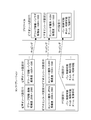
- FIG. 1 is a diagram showing an example of mapping a configuration to a profile by ONVIF. Thus, one is selected from each of one or more video source settings, video encoder settings, and PTZ settings, and is mapped to a profile.
- the surveillance camera prepares a profile in which each configuration is mapped, or the client device acquires each configuration from the surveillance camera and maps the configuration to the profile.
- mapping to a profile in a client device it is necessary to map in consideration of the dependency between each configuration.
- image dewarping information is designated in the video source setting.
- PTZ settings can not be mapped to profiles.
- Japanese Patent Application Laid-Open No. 2014-107590 discloses an imaging device for adjusting between setting values of a video source setting and a video encoder setting.
- An acquisition unit for acquiring association information indicating a relationship between a profile, which is a setting information group including a plurality of setting information, and dewarp information related to a fisheye image, and the association information acquired by the acquisition unit
- associating means for associating the video source setting, the video encoding setting and the PTZ setting with the profile.
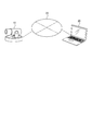
- FIG. 2 is a diagram showing an example of a system configuration including the monitoring camera 10.
- the monitoring camera 10 and the client device 20 are connected in a mutually communicable state via the network 35.
- the client device 20 is an external device that transmits control commands such as a profile tying setting command and a profile acquisition command to the monitoring camera 10.
- the monitoring camera 10 transmits a response to the command to the client device 20.
- the dewarping information is information related to the dewarping process.
- a fish-eye image captured through a fish-eye lens is often subjected to processing of both image cutting and distortion correction called dewarping.
- the clipped image is called in various ways depending on the clip position, the number of clips, and the possibility of changing the clip position.
- the cutting range is wide, it may be called a panorama.
- the cutting out four images whose cutting positions can be changed from a fish-eye image it may be called a four-screen mode or a four-frame cutting mode.
- two panoramic images are cut out, it is sometimes called double panoramic mode.
- distortion correction processing in the dewarping processing is processing for adjusting distortion and inclination caused by a fisheye lens, and converting the image into an image in almost the same state as a human being visually recognizes.
- de-warping processing performing at least the above-described correction processing is referred to as de-warping processing, and information related thereto is referred to as de-warping information. That is, information indicating whether or not the dewarping process has been performed (or whether or not the dewarping process should be performed), information indicating the type of the dewarping process (its name), and the like are referred to as dewarping information.
- the dewarp information may simply indicate the name (fisheye, cutout, panorama, etc.) of each video stream related to the fisheye image, or may be an index indicating the name. It may be any information that indicates what kind of video stream is to be transmitted and received based on a fisheye image between at least the surveillance camera and the client device.
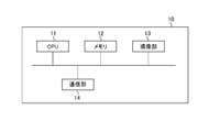
- FIG. 3A is a diagram showing an example of a hardware configuration of the monitoring camera 10. As shown in FIG.
- the CPU 11 controls the entire surveillance camera 10.
- the memory 12 is used as a storage area for various data.
- a storage area there are a program storage area executed by the CPU 11, a work area during program execution, and the like.
- a setting value storage area such as a setting value (configuration) of the monitoring camera, a profile, a correlating setting between the profile and the dewarp information, and an installation situation of the camera such as ceiling attachment or wall attachment.
- storage areas there are a dependency relation table between configurations, information storage areas such as pan / tilt / zoom support information for each dewarp information, storage areas of image data generated by the imaging unit 13 described later, and the like.
- dewarp information for determining distortion correction of the image and the presence or absence of the clipping range
- a video source configuration (Video Source Configuration) including the resolution that the sensor can output.
- video encoder setting (Video Encoder Configuration) including an encoding type and resolution of image encoding, and the like.
- PTZ setting PTZ Configuration
- the configuration is mapped (correlated) to a profile (Profile) specified for control of the surveillance camera, and the surveillance camera performs video distribution, PTZ control, etc. with the contents of the configuration mapped to the profile.
- Profile profile
- the imaging unit 13 captures an image of a subject formed by the imaging optical system of the monitoring camera 10, converts the acquired analog signal into digital data, and outputs the digital data to the memory 12 as a captured image.
- the CPU 11 receives an image acquisition event from the imaging unit 13.
- the communication unit 14 is used when receiving each control command such as profile acquisition from an external device, and when transmitting a response to each control command to the external device.
- the CPU 11 receives a command reception event from the communication unit 14.
- the hardware configuration of the surveillance camera 10 shown in FIG. 3A is an example, and in addition to the one shown in FIG. 3A, the surveillance camera 10 includes an audio input unit, an audio output unit, an image analysis processing unit, etc. You may have as.
- FIG. 3B is a diagram showing an example of the hardware configuration of the client device 20. As shown in FIG.
- the CPU 21 controls the entire client device 20.
- the memory 22 is mainly used as a storage area for various data, such as a program storage area executed by the CPU 21 and a work area during program execution.
- the display unit 23 is configured of, for example, an LCD, an organic EL display, or the like.
- the display unit 23 displays various setting screens and display screens including a setting screen for linking the profile and the warp information to the user of the client device 20, a viewer of the video received from the monitoring camera 10, various messages, and the like.
- the input unit 24 includes, for example, a button, an arrow key, a touch panel, and a mouse, and notifies the CPU 21 of the content of the screen operation by the user.
- the communication unit 25 is used for transmitting a response to each control command or receiving a video stream from the monitoring camera 10 when transmitting each control command including a profile tying setting command and profile acquisition to the monitoring camera 10. Ru.
- FIG. 4A is a view showing an example of the software configuration of the monitoring camera 10. As shown in FIG.
- the control unit 100 controls the entire processing of the surveillance camera 10.
- the imaging control unit 101 controls the imaging unit 13.
- the imaging control unit 101 changes the imaging range of the imaging unit 13 to tilt drive, pan drive, or zoom drive according to the pan, tilt, or zoom value input by the control unit 100.
- the compression encoding unit 102 applies JPEG or H.264 to the captured image output from the imaging unit 13.
- Image data is generated by performing compression encoding processing based on the format such as H.265 and output to the memory 12.
- the imaging control unit 101 may be mounted on the monitoring camera 10 as a hardware configuration.
- the compression encoding unit 102 may also be mounted on the monitoring camera 10 as a hardware configuration.
- FIG. 4B is a diagram showing an example of the software configuration of the client device 20. As shown in FIG.
- the control unit 200 controls the entire processing of the client device 20.
- the decoding unit 201 performs JPEG or H.264 compression-encoded image data received via the communication unit 25. H.264. Decoding is performed based on the format such as 265 and expanded in the memory 22.
- the decryption unit 201 may be implemented in the client device 20 as a hardware configuration.
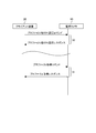
- FIG. 5 is a sequence diagram of processing relating to a profile tying setting command and a profile acquisition command of the monitoring camera 10.
- the control unit 200 of the client device 20 transmits a profile tying setting command including tying information between the profile and the dewarp information.
- the control unit 100 of the monitoring camera 10 receives a profile tying setting command, performs profile tying setting command processing 30, and transmits a profile tying setting response to the client device 20 as a response.
- the control unit 200 of the client device 20 receives the profile tying setting response.
- the profile is a setting information group including a plurality of setting information as shown in FIG.
- the linking information is an example of information indicating the association between the profile and the dewarp information.
- the control unit 200 of the client device 20 transmits a profile acquisition command.
- the control unit 100 of the monitoring camera 10 receives the profile acquisition command, performs profile acquisition command processing 31, and transmits a profile acquisition response to the client device 20 as a response.
- the control unit 200 of the client device 20 receives the profile acquisition response.
- the profile association setting command and the profile acquisition command are transmitted from the same client device 20, different commands may be transmitted from different client devices 20.
- the protocol of each command is not limited, and the protocol of the command is ONVIF, a control protocol unique to the surveillance camera, or the like.
- the profile tying setting command processing 30 and the profile acquisition command processing 31 are examples of information processing.
- FIG. 6 is a setting screen for correlating the profile and the dewarp information.
- the setting screen of FIG. 6 is displayed on the display unit 23 of the client device 20.
- a list of identifier IDs of profiles set in the monitoring camera 10 is displayed.
- the user operates the input unit 24 of the client device 20 and selects the dewarp information to be associated with the profile from the dewarp information selection box 42.
- the control unit 200 of the client device 20 transmits a profile tying setting command to the monitoring camera 10.
- Data for displaying the setting screen shown in FIG. 6 may be included in the client device 20, or may be included in the monitoring camera 10, and in response to a request from the client device 20, the web browser of the client device 20 It may be displayed on the like.
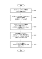
- FIG. 7 is a flowchart showing an example of the profile tying setting command processing 30.
- step S51 the control unit 100 stores, in the memory 12, the profile connection information (the connection information between the profile and the dewarp information) specified by the profile connection setting command, and the process proceeds to step S52.
- control unit 100 acquires the video source setting, the video encoder setting, and the PTZ setting dependency relationship table 60 from the memory 12, and transitions to S53.
- FIG. 8 is a diagram showing an example of a dependency relationship table between configurations that can be mapped to a profile.
- the video encoder setting that can be mapped to the profile together with the video source setting 1 is the video encoder setting 1 and there is no PTZ setting.
- a video encoder setting that can be mapped to a profile together with the video source setting 2 is a video encoder setting 2 and a PTZ setting is a PTZ setting 1.
- control unit 100 acquires the association information between the profile and the dewarp information from the memory 12, maps the video source setting corresponding to the dewarp information to the profile, and shifts to S54.
- the process of S53 is an example of a process of acquiring tying information between the profile and the dewarp information.
- the control unit 100 maps the video encoding setting and the PTZ setting corresponding to the mapped video source setting to the profile with the contents of the dependency relationship table.
- the processes of S53 and S54 are an example of an associating process of associating the video source setting, the video encoding setting, and the PTZ setting with the profile based on the association information.
- the process of S54 is an example of the process of mapping to the video encoding setting that can be set to the mapped video source setting, the PTZ setting, and the profile based on the dependency relationship table.
- control unit 100 generates a response to the profile tying setting command, and transmits a response to the profile tying setting command to the client device 20.
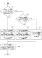
- FIG. 9 is a flowchart showing an example of the profile acquisition command process 31.
- step S71 the control unit 100 acquires the ONVIF service name included in the profile setting command, and the ONVIF service name is JPEG as video encoding. It is determined whether or not it is a Meida service that supports H.264. The control unit 100 determines that the ONVIF service name is JPEG as video encoding and H.264. If the service is a Meida service that supports H.264, the process transitions to step S72; otherwise, the process transitions to step S73.
- the control unit 100 rearranges the order of the profiles returned as a response to the profile acquisition command. First, the control unit 100 determines that the encoding type of the video encoder setting included in the profile is H.264. H.264, JPEG, H. Sort the profiles in the order of 265. Then, the control unit 100 further rearranges profiles of the same encoding type in ascending order of profile ID in alphabetical order, and shifts to S76.
- the control unit 100 acquires the ONVIF service name included in the profile setting command, and the ONVIF service name is JPEG as video encoding. H.264. It is determined whether or not it is a Media2 service that supports H.265. The control unit 100 determines that the ONVIF service name is JPEG as video encoding and H.264. H.264. If it is a Media2 service that supports H.265, the process goes to S74; otherwise, it goes to S75.
- the control unit 100 rearranges the order of the profiles returned as a response to the profile acquisition command.
- the control unit 100 determines that the encoding type of the video encoder setting included in the profile is H.264. H.265. Sort the profiles in the order of H.264 and JPEG. After that, the control unit 100 further rearranges profiles of the same encoding type in ascending order of profile ID alphabetically, and transitions to S76.
- control unit 100 rearranges the order of the profiles returned as a response to the profile acquisition command.
- the control unit 100 rearranges the profiles in ascending order of profile ID alphabetically, and transitions to S76.
- control unit 100 creates a response of the profile acquisition command using the rearranged profile, and transmits the response of the profile acquisition command to the client device 20.
- FIG. 9 shows an example of control for determining the order of responding profiles according to the service name included in the profile acquisition command
- the order of responding profiles is determined according to the version information instead of the service name. Control may be performed.
- the process in FIG. 9 is an example of a process of controlling to finally transmit to the client device 20 a profile including a video encoder setting in which an unsupported encoding type is set according to the service name included in the profile acquisition command. It is.
- the user does not have to consider the dependency between the video source setting, the video encoder setting, and the PTZ setting in the first embodiment.
- Video source settings, video encoder settings, and PTZ settings adapted to the dewarp information linked to the profile by the user can be mapped to the profile based on the dependency relationship table between the monitoring camera 10 between configurations. Therefore, appropriate video distribution and PTZ control can be performed.
- the profile returned by the profile acquisition command can be preferentially returned by a profile that can be handled by the client device 20.
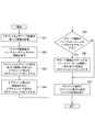
- control unit 100 stores the profile tying information specified in the profile tying setting command in the memory 12, and transitions to S82.
- control unit 100 acquires pan / tilt / zoom support information indicating whether pan / tilt / zoom is possible for each dewarp information from the memory 12, and transitions to S83.
- control unit 100 maps the video source setting corresponding to the dewarp information from the memory 12 to the profile, and transitions to S84.
- step S84 the control unit 100 maps a video encoding setting having a resolution that includes the resolution that can be output by the sensor in the video source setting to the profile, and the process transitions to step S85.
- step S85 the control unit 100 determines whether the dewarp information supports pan, tilt, or zoom from the pan, tilt, or zoom support information.
- the control unit 100 transitions to S86 when the dewarp information supports any of pan, tilt, and zoom, and transitions to S87 when neither is supported.
- step S86 the control unit 100 maps the PTZ setting that matches the pan, tilt, and zoom support information on the profile, and the process transitions to step S87.
- control unit 100 In S87, the control unit 100 generates a response to the profile tying setting command, and transmits a response to the profile tying setting command to the client device 20.
- the user does not have to consider the dependency between the video source setting, the video encoder setting, and the PTZ setting.
- the surveillance camera 10 can map video source settings, video encoder settings, and PTZ settings that match from the resolution of the video source settings and the video encoder settings and the pan-tilt-zoom support information to the profile. Therefore, appropriate video distribution and PTZ control can be performed.
- the profile returned by the profile acquisition command can be preferentially returned by a profile that can be handled by the client device 20.
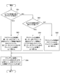
- control unit 100 acquires the installation state of the camera from the memory 12 and determines whether or not the ceiling is attached. The control unit 100 transitions to S92 if the ceiling is attached, and transitions to S93 otherwise.
- the control unit 100 rearranges the order of the profiles returned as a response to the profile acquisition command.
- the dewarping information of the video source setting included in the profile is a fisheye (without dewarping processing), cutout 1 (with dewarping processing capable of changing the cutout position two-dimensionally), panorama (with dewarping processing)
- the profiles of the same dewarp information are further sorted in the ascending order of profile ID alphabetically after the profiles are rearranged in the order of two-dimensional cutout position change), and the process proceeds to S96.
- control unit 100 acquires the installation state of the camera from the memory 12 and determines whether or not the wall is attached. If the control unit 100 is wall-mounted, the process transitions to step S94. Otherwise, the control unit 100 transitions to step S95.
- the control unit 100 rearranges the order of the profiles returned as a response to the profile acquisition command. First, after the control unit 100 rearranges the profiles in the order of panorama, cutout 1, and fisheye in the video source setting dewarp information included in the profile, the profiles of the same dewarp information are further rearranged in ascending order of profile ID in alphabetical order. , S96.
- step S95 the control unit 100 rearranges the order of profiles returned as a response to the profile acquisition command.
- the control unit 100 rearranges the profile IDs in ascending alphabetical order, and transitions to S96.
- control unit 100 creates a response of the profile acquisition command using the rearranged profile, and transmits the response of the profile acquisition command to the client device 20.
- the user does not have to consider the dependency between the video source setting, the video encoder setting, and the PTZ setting.
- Video source settings, video encoder settings, and PTZ settings adapted to the dewarp information linked to the profile by the user can be mapped to the profile based on the dependency relationship table between the monitoring camera 10 between configurations. Therefore, appropriate video distribution and PTZ control can be performed.
- the profile returned by the profile acquisition command can be preferentially returned in the profile assumed to be used in the installation state of the surveillance camera such as ceiling attachment or wall attachment.
- the present invention supplies a program that implements one or more functions of the above-described embodiments to a system or apparatus via a network or a storage medium. And, it is also possible to realize the processing in which one or more processors in the computer of the system or apparatus read and execute the program. It can also be implemented by a circuit (eg, an ASIC) that implements one or more functions.
- a circuit eg, an ASIC
- the hardware configuration of the monitoring camera 10 described above is an example, and for example, a plurality of CPUs, memories, communication units, and the like may be provided. Also, a plurality of CPUs may execute processing based on programs and using data stored in a plurality of memories. Alternatively, a GPU (Graphics Processing Unit) may be used instead of the CPU.
- a GPU Graphics Processing Unit
Landscapes
- Physics & Mathematics (AREA)
- Engineering & Computer Science (AREA)
- General Physics & Mathematics (AREA)
- Multimedia (AREA)
- Signal Processing (AREA)
- Theoretical Computer Science (AREA)
- Optics & Photonics (AREA)
- Computer Vision & Pattern Recognition (AREA)
- Closed-Circuit Television Systems (AREA)
- Studio Devices (AREA)
- Camera Data Copying Or Recording (AREA)
Priority Applications (1)
| Application Number | Priority Date | Filing Date | Title |
|---|---|---|---|
| US16/775,009 US11010864B2 (en) | 2017-08-01 | 2020-01-28 | Image capturing apparatus, control method, and storage medium |
Applications Claiming Priority (2)
| Application Number | Priority Date | Filing Date | Title |
|---|---|---|---|
| JP2017-149095 | 2017-08-01 | ||
| JP2017149095A JP6968610B2 (ja) | 2017-08-01 | 2017-08-01 | 撮像装置、情報処理方法及びプログラム |
Related Child Applications (1)
| Application Number | Title | Priority Date | Filing Date |
|---|---|---|---|
| US16/775,009 Continuation US11010864B2 (en) | 2017-08-01 | 2020-01-28 | Image capturing apparatus, control method, and storage medium |
Publications (1)
| Publication Number | Publication Date |
|---|---|
| WO2019026666A1 true WO2019026666A1 (ja) | 2019-02-07 |
Family
ID=65232802
Family Applications (1)
| Application Number | Title | Priority Date | Filing Date |
|---|---|---|---|
| PCT/JP2018/027463 Ceased WO2019026666A1 (ja) | 2017-08-01 | 2018-07-23 | 撮像装置、情報処理方法及びプログラム |
Country Status (3)
| Country | Link |
|---|---|
| US (1) | US11010864B2 (enExample) |
| JP (1) | JP6968610B2 (enExample) |
| WO (1) | WO2019026666A1 (enExample) |
Cited By (1)
| Publication number | Priority date | Publication date | Assignee | Title |
|---|---|---|---|---|
| CN112200875A (zh) * | 2020-12-02 | 2021-01-08 | 武汉光谷信息技术股份有限公司 | 非量测相机交叉耦合误差补偿与影像匹配纠正方法及系统 |
Families Citing this family (2)
| Publication number | Priority date | Publication date | Assignee | Title |
|---|---|---|---|---|
| JP7306857B2 (ja) * | 2019-04-05 | 2023-07-11 | 株式会社キーエンス | 画像検査システム |
| US20260046386A1 (en) * | 2024-08-12 | 2026-02-12 | Security Camera Maintenance Company | Camera monitoring systems and methods |
Citations (5)
| Publication number | Priority date | Publication date | Assignee | Title |
|---|---|---|---|---|
| JP2013243544A (ja) * | 2012-05-21 | 2013-12-05 | Canon Inc | 撮像装置、マスク画像設定方法、および、プログラム |
| JP2013258538A (ja) * | 2012-06-12 | 2013-12-26 | Canon Inc | 撮像制御装置、撮像制御方法及びプログラム |
| JP2015080142A (ja) * | 2013-10-18 | 2015-04-23 | キヤノン株式会社 | 撮像装置、撮像システム、撮像装置の制御方法、撮像システムの制御方法、及びプログラム |
| JP2015222931A (ja) * | 2014-05-23 | 2015-12-10 | キヤノン株式会社 | 画像処理装置、及び外部装置 |
| JP2017017446A (ja) * | 2015-06-29 | 2017-01-19 | キヤノン株式会社 | 情報処理装置およびその制御方法、並びにプログラム |
Family Cites Families (52)
| Publication number | Priority date | Publication date | Assignee | Title |
|---|---|---|---|---|
| KR100327377B1 (ko) * | 2000-03-06 | 2002-03-06 | 구자홍 | 디지털 영상 수신기와 디지털 디스플레이 장치 사이에서디지털 영상 신호를 디스플레이 하는 방법 |
| US8479253B2 (en) * | 2007-12-17 | 2013-07-02 | Ati Technologies Ulc | Method, apparatus and machine-readable medium for video processing capability communication between a video source device and a video sink device |
| KR101623890B1 (ko) * | 2007-12-20 | 2016-06-07 | 에이티아이 테크놀로지스 유엘씨 | 비디오 소스 디바이스와 비디오 싱크 디바이스를 구비하는 시스템에서의 비디오 프로세싱 조정 |
| US11082665B2 (en) * | 2010-11-05 | 2021-08-03 | Razberi Secure Technologies, Llc | System and method for a security system |
| US10477158B2 (en) * | 2010-11-05 | 2019-11-12 | Razberi Technologies, Inc. | System and method for a security system |
| US9704393B2 (en) * | 2011-01-11 | 2017-07-11 | Videonetics Technology Private Limited | Integrated intelligent server based system and method/systems adapted to facilitate fail-safe integration and/or optimized utilization of various sensory inputs |
| WO2013072981A1 (ja) * | 2011-11-14 | 2013-05-23 | キヤノン株式会社 | 撮像装置、制御装置、制御方法、及びプログラム |
| US9066129B2 (en) * | 2012-04-24 | 2015-06-23 | Comcast Cable Communications, Llc | Video presentation device and method |
| JP5955171B2 (ja) * | 2012-09-11 | 2016-07-20 | キヤノン株式会社 | 送信装置、受信装置、送信方法、受信方法、及びプログラム |
| JP6204655B2 (ja) | 2012-11-22 | 2017-09-27 | キヤノン株式会社 | 撮像装置、撮像装置の制御方法、及びプログラム |
| JP6214178B2 (ja) * | 2013-01-25 | 2017-10-18 | キヤノン株式会社 | 撮像装置、クライアント装置、撮像システム、撮像装置の制御方法、クライアント装置の制御方法、および撮像システムの制御方法 |
| JP6103999B2 (ja) * | 2013-03-15 | 2017-03-29 | キヤノン株式会社 | 画像データ送信装置、画像データ受信装置、画像データ送信方法、画像データ受信方法、及びプログラム |
| JP6091269B2 (ja) * | 2013-03-15 | 2017-03-08 | キヤノン株式会社 | 撮像装置、クライアント装置、撮像システム、撮像装置の制御方法、クライアント装置の制御方法、および撮像システムの制御方法 |
| KR101321527B1 (ko) * | 2013-03-27 | 2013-10-28 | 조철휘 | 열교환기를 활용한 건조기 |
| JP6218471B2 (ja) * | 2013-07-20 | 2017-10-25 | キヤノン株式会社 | 撮像装置、外部装置、撮像システム、撮像装置の制御方法、外部装置の制御方法、撮像システムの制御方法、及びプログラム |
| JP6327816B2 (ja) * | 2013-09-13 | 2018-05-23 | キヤノン株式会社 | 送信装置、受信装置、送受信システム、送信装置の制御方法、受信装置の制御方法、送受信システムの制御方法、及びプログラム |
| JP6234165B2 (ja) * | 2013-10-28 | 2017-11-22 | キヤノン株式会社 | 撮像装置、外部装置、撮像システム、撮像装置の制御方法、外部装置の制御方法、撮像システムの制御方法、及びプログラム |
| JP2015088786A (ja) * | 2013-10-28 | 2015-05-07 | キヤノン株式会社 | 撮像装置、撮像システム、撮像装置の制御方法、撮像システムの制御方法、及びプログラム |
| JP6415037B2 (ja) * | 2013-11-12 | 2018-10-31 | キヤノン株式会社 | 撮像装置、クライアント装置、撮像装置の制御方法、クライアント装置の制御方法、及びプログラム |
| JP6338356B2 (ja) * | 2013-11-13 | 2018-06-06 | キヤノン株式会社 | 撮像装置、外部装置、撮像システム、撮像装置の制御方法、外部装置の制御方法、撮像システムの制御方法、及びプログラム |
| US9769369B2 (en) * | 2013-11-21 | 2017-09-19 | Canon Kabushiki Kaisha | Imaging apparatus, imaging system, control method of imaging apparatus, and storage medium |
| WO2015125420A1 (en) * | 2014-02-19 | 2015-08-27 | Canon Kabushiki Kaisha | Imaging apparatus and imaging system |
| JP6305110B2 (ja) * | 2014-02-28 | 2018-04-04 | キヤノン株式会社 | 撮像装置、及び撮像システム |
| JP6399766B2 (ja) * | 2014-03-07 | 2018-10-03 | キヤノン株式会社 | 撮像装置、撮像装置の制御方法及びプログラム |
| JP6230453B2 (ja) * | 2014-03-17 | 2017-11-15 | キヤノン株式会社 | 撮像装置及びその制御方法 |
| JP2015177467A (ja) * | 2014-03-17 | 2015-10-05 | キヤノン株式会社 | 撮像装置及びその制御方法 |
| JP6333019B2 (ja) * | 2014-03-28 | 2018-05-30 | キヤノン株式会社 | 撮像装置、撮像方法及びプログラム |
| JP2015220692A (ja) * | 2014-05-20 | 2015-12-07 | キヤノン株式会社 | 撮像装置、情報処理装置、撮像システム、及びそれらの制御方法、ならびにプログラム |
| JP6355428B2 (ja) * | 2014-05-21 | 2018-07-11 | キヤノン株式会社 | 撮像装置 |
| JP2015233208A (ja) * | 2014-06-09 | 2015-12-24 | キヤノン株式会社 | 画像処理装置 |
| JP6444073B2 (ja) * | 2014-06-25 | 2018-12-26 | キヤノン株式会社 | 画像処理装置 |
| TWI578781B (zh) * | 2014-10-21 | 2017-04-11 | 群暉科技股份有限公司 | 藉助於全景地圖來管理一監視系統之方法與裝置 |
| CN107005405B (zh) * | 2014-11-13 | 2020-12-15 | 佳能株式会社 | 信息处理装置、控制方法及存储介质 |
| JP6566626B2 (ja) * | 2014-11-18 | 2019-08-28 | キヤノン株式会社 | 撮像装置 |
| JP6425569B2 (ja) * | 2015-01-30 | 2018-11-21 | キヤノン株式会社 | 通信装置 |
| JP6478777B2 (ja) * | 2015-04-13 | 2019-03-06 | キヤノン株式会社 | 制御装置及びその制御方法、プログラム |
| WO2016179303A1 (en) * | 2015-05-04 | 2016-11-10 | Kamama, Inc. | System and method of vehicle sensor management |
| JP6676347B2 (ja) * | 2015-11-09 | 2020-04-08 | キヤノン株式会社 | 制御装置、制御方法、及びプログラム |
| US9948983B2 (en) * | 2016-03-31 | 2018-04-17 | Rovi Guides, Inc. | Systems and methods for allowing access to a different version of the media asset |
| KR102474745B1 (ko) * | 2016-06-02 | 2022-12-05 | 한화테크윈 주식회사 | 모니터링 장치 및 모니터링 시스템 |
| GB2556925B (en) * | 2016-11-25 | 2020-07-29 | Canon Kk | Method and system for determining encoding parameters of video sources in large scale video surveillance systems |
| CN109997175B (zh) * | 2016-12-02 | 2023-12-08 | 皇家Kpn公司 | 确定虚拟对象的大小 |
| US20190045109A1 (en) * | 2017-08-02 | 2019-02-07 | Canon Kabushiki Kaisha | Information processing apparatus, information processing method, and storage medium |
| JP6980450B2 (ja) * | 2017-08-09 | 2021-12-15 | キヤノン株式会社 | 制御装置、制御方法、及びプログラム |
| JP7073120B2 (ja) * | 2018-01-26 | 2022-05-23 | キヤノン株式会社 | 映像送信装置、情報処理装置、システム、情報処理方法及びプログラム |
| US10904423B2 (en) * | 2018-03-16 | 2021-01-26 | Hanwha Techwin Co., Ltd. | Image providing apparatus and method |
| JP7250440B2 (ja) * | 2018-05-31 | 2023-04-03 | キヤノン株式会社 | 撮影装置、情報処理装置、情報処理方法、およびプログラム |
| JP7065329B2 (ja) * | 2018-09-27 | 2022-05-12 | パナソニックIpマネジメント株式会社 | 窒化物半導体装置及びその製造方法 |
| US11496472B2 (en) * | 2018-11-16 | 2022-11-08 | Mutualink, Inc. | System and method for secure access to camera systems |
| JP7191663B2 (ja) * | 2018-12-04 | 2022-12-19 | キヤノン株式会社 | 撮像装置、制御方法及びプログラム |
| KR102721188B1 (ko) * | 2019-01-07 | 2024-10-24 | 한화비전 주식회사 | 설정 장치 및 이의 제어 방법 |
| JP7204569B2 (ja) * | 2019-04-05 | 2023-01-16 | キヤノン株式会社 | 撮像装置、システム、撮像装置の制御方法、プログラム |
-
2017
- 2017-08-01 JP JP2017149095A patent/JP6968610B2/ja active Active
-
2018
- 2018-07-23 WO PCT/JP2018/027463 patent/WO2019026666A1/ja not_active Ceased
-
2020
- 2020-01-28 US US16/775,009 patent/US11010864B2/en active Active
Patent Citations (5)
| Publication number | Priority date | Publication date | Assignee | Title |
|---|---|---|---|---|
| JP2013243544A (ja) * | 2012-05-21 | 2013-12-05 | Canon Inc | 撮像装置、マスク画像設定方法、および、プログラム |
| JP2013258538A (ja) * | 2012-06-12 | 2013-12-26 | Canon Inc | 撮像制御装置、撮像制御方法及びプログラム |
| JP2015080142A (ja) * | 2013-10-18 | 2015-04-23 | キヤノン株式会社 | 撮像装置、撮像システム、撮像装置の制御方法、撮像システムの制御方法、及びプログラム |
| JP2015222931A (ja) * | 2014-05-23 | 2015-12-10 | キヤノン株式会社 | 画像処理装置、及び外部装置 |
| JP2017017446A (ja) * | 2015-06-29 | 2017-01-19 | キヤノン株式会社 | 情報処理装置およびその制御方法、並びにプログラム |
Cited By (1)
| Publication number | Priority date | Publication date | Assignee | Title |
|---|---|---|---|---|
| CN112200875A (zh) * | 2020-12-02 | 2021-01-08 | 武汉光谷信息技术股份有限公司 | 非量测相机交叉耦合误差补偿与影像匹配纠正方法及系统 |
Also Published As
| Publication number | Publication date |
|---|---|
| US11010864B2 (en) | 2021-05-18 |
| JP2019029888A (ja) | 2019-02-21 |
| JP6968610B2 (ja) | 2021-11-17 |
| US20200167892A1 (en) | 2020-05-28 |
Similar Documents
| Publication | Publication Date | Title |
|---|---|---|
| US9491410B2 (en) | Apparatus and method for information processing and program | |
| JP6415037B2 (ja) | 撮像装置、クライアント装置、撮像装置の制御方法、クライアント装置の制御方法、及びプログラム | |
| US10187575B2 (en) | Image acquisition apparatus, method of controlling image acquisition apparatus, computer-readable recording medium non-transitorily storing control program of image acquisition apparatus, and image acquisition system | |
| US8687119B2 (en) | Video display apparatus and control method thereof, and video output apparatus and control method thereof | |
| JP2015195509A (ja) | 制御装置、画像入力装置、及び、それらの制御方法 | |
| WO2019026666A1 (ja) | 撮像装置、情報処理方法及びプログラム | |
| CN105659581B (zh) | 摄像设备、摄像系统和用于控制摄像设备的方法 | |
| JP6980450B2 (ja) | 制御装置、制御方法、及びプログラム | |
| US8395669B2 (en) | Image data transmission apparatus and method, remote display control apparatus and control method thereof, program, and storage medium | |
| JP2015088785A (ja) | 撮像装置、外部装置、撮像システム、撮像装置の制御方法、外部装置の制御方法、撮像システムの制御方法、及びプログラム | |
| JP7073120B2 (ja) | 映像送信装置、情報処理装置、システム、情報処理方法及びプログラム | |
| JP2007053568A (ja) | モニタディスプレイ装置及びそれを用いた監視システム | |
| CN103581619A (zh) | 监视摄像机控制装置 | |
| JP6184133B2 (ja) | 撮像装置 | |
| JP2014107775A (ja) | 電子カメラ | |
| JP2015088786A (ja) | 撮像装置、撮像システム、撮像装置の制御方法、撮像システムの制御方法、及びプログラム | |
| JP2015023417A (ja) | 通信装置、撮像装置およびそれらの制御方法、並びにプログラム | |
| JP2010032920A (ja) | 映像表示装置及び映像表示方法 | |
| US11842518B2 (en) | Camera apparatus, control method for camera apparatus, and storage medium | |
| JP7802520B2 (ja) | 情報処理装置、情報処理方法、撮像装置、制御方法およびプラグラム | |
| JP2012074999A (ja) | 画像データ伝送システム、サーバ装置、クライアント端末、画像データ伝送方法、及び制御プログラム | |
| JP2006308767A (ja) | 映像表示方法及び映像表示システム | |
| JP2010045539A (ja) | 情報処理装置及びその制御方法 | |
| JP2019029995A (ja) | 情報処理装置、情報処理方法及びプログラム | |
| JP2019062470A (ja) | 情報処理装置、情報処理方法、及びプログラム |
Legal Events
| Date | Code | Title | Description |
|---|---|---|---|
| 121 | Ep: the epo has been informed by wipo that ep was designated in this application |
Ref document number: 18841716 Country of ref document: EP Kind code of ref document: A1 |
|
| NENP | Non-entry into the national phase |
Ref country code: DE |
|
| 122 | Ep: pct application non-entry in european phase |
Ref document number: 18841716 Country of ref document: EP Kind code of ref document: A1 |