WO2019022043A1 - 首振り式剃刀 - Google Patents
首振り式剃刀 Download PDFInfo
- Publication number
- WO2019022043A1 WO2019022043A1 PCT/JP2018/027611 JP2018027611W WO2019022043A1 WO 2019022043 A1 WO2019022043 A1 WO 2019022043A1 JP 2018027611 W JP2018027611 W JP 2018027611W WO 2019022043 A1 WO2019022043 A1 WO 2019022043A1
- Authority
- WO
- WIPO (PCT)
- Prior art keywords
- blade assembly
- flexible
- razor
- swing
- support
- Prior art date
Links
Images
Classifications
-
- B—PERFORMING OPERATIONS; TRANSPORTING
- B26—HAND CUTTING TOOLS; CUTTING; SEVERING
- B26B—HAND-HELD CUTTING TOOLS NOT OTHERWISE PROVIDED FOR
- B26B21/00—Razors of the open or knife type; Safety razors or other shaving implements of the planing type; Hair-trimming devices involving a razor-blade; Equipment therefor
- B26B21/08—Razors of the open or knife type; Safety razors or other shaving implements of the planing type; Hair-trimming devices involving a razor-blade; Equipment therefor involving changeable blades
- B26B21/14—Safety razors with one or more blades arranged transversely to the handle
- B26B21/22—Safety razors with one or more blades arranged transversely to the handle involving several blades to be used simultaneously
- B26B21/222—Safety razors with one or more blades arranged transversely to the handle involving several blades to be used simultaneously with the blades moulded into, or attached to, a changeable unit
- B26B21/225—Safety razors with one or more blades arranged transversely to the handle involving several blades to be used simultaneously with the blades moulded into, or attached to, a changeable unit the changeable unit being resiliently mounted on the handle
-
- B—PERFORMING OPERATIONS; TRANSPORTING
- B26—HAND CUTTING TOOLS; CUTTING; SEVERING
- B26B—HAND-HELD CUTTING TOOLS NOT OTHERWISE PROVIDED FOR
- B26B21/00—Razors of the open or knife type; Safety razors or other shaving implements of the planing type; Hair-trimming devices involving a razor-blade; Equipment therefor
- B26B21/40—Details or accessories
- B26B21/52—Handles, e.g. tiltable, flexible
- B26B21/521—Connection details, e.g. connection to razor heads
Definitions
- the present invention relates to a swing razor in which a razor head assembled with a blade can move against the head of a holder against elastic force.
- Patent Document 1 discloses a conventional safety razor.
- the safety razor of Patent Document 1 includes a handle, a replaceable blade unit having a blade, and a joint located between the handle and the replaceable blade unit.
- the handle includes a pivot for pivotally supporting the joint and an elastic member for biasing the joint towards the joint's neutral position.
- the joint is provided with a pair of journal axes for supporting the replaceable blade unit.
- the replaceable blade unit includes a pair of journal bearings provided corresponding to a pair of journal axes of the joint, and an elastic piece for urging the replaceable blade unit toward the neutral position of the replaceable blade unit.
- the pair of journal axes of the joint is received by the pair of journal bearings of the replaceable blade unit, whereby the replaceable blade unit is supported by the joint so as to be pivotable around both journal axes. More specifically, the replaceable blade unit swings around both journal axes against the elastic force of the elastic piece with reference to the neutral position of the replaceable blade unit. Furthermore, the joint supporting the replaceable blade unit pivots with the replaceable blade unit around the pivot axis against the elastic force of the elastic member with reference to the neutral position of the joint.
- the invention relates to a swing razor comprising a holder having a head and a razor head having a blade, wherein the razor head can be moved against a resilient force from a neutral position relative to the head of the holder. It is intended to simplify the support structure for supporting the head of the holder.
- the swing razor includes a holder having a head and a razor head attached to the holder, the razor head including a blade assembly having a blade, an elastic support, and the like.
- a connecting portion continuous with the head of the holder, and the blade assembly has a front side to which a blade edge of the blade is exposed and a back side opposite to the front side, and the elastic support
- the body is located on the back side, and the elastic support includes a support portion for supporting the blade assembly and a flexible portion located between the support and the connection portion, the blade assembly Is biased by the flexible portion of the elastic support at a neutral position, and the blade assembly moves from the neutral position against the biasing force of the flexible portion. It can move to one movement position.
- the blade assembly in the razor head attached to the holder, since the blade assembly is supported by the flexible portion, the blade assembly can be moved relative to the neutral position against the biasing force of the flexible portion.
- the supporting structure to support can be simplified.
- the flexible portion since the flexible portion is provided on the back side of the blade assembly, the flexible portion can be easily disposed relatively close to the blade. Therefore, when using the swing-type razor, the blade assembly can be operated smoothly on the skin surface to improve the feel on the skin surface.
- each of the connection portion and the blade assembly preferably has a fulcrum portion for supporting the blade assembly with respect to the connection portion.
- the blade assembly when the blade assembly is moved against the biasing force of the flexible portion when the swing razor is used, the blade assembly is supported by the fulcrum portion, so that the blade assembly is The movement can be stabilized.
- the fulcrum portions abut each other at the neutral position and the movement position of the blade assembly, the blade assembly is supported by the abutment of the fulcrum portions at both the neutral position and the movement position, The movement of the blade assembly relative to the connection can be stabilized between the neutral position and the movement position.
- the support portion is one of two support portions for supporting the blade assembly
- the flexible portion is one of two flexible portions.
- One of the two flexible portions is located between one of the two support portions and the connection portion, and the other of the two flexible portions is one of the two support portions. Preferably, it is located between the other and the connection.
- the flexible portion can be provided in a stable state between each support portion and the connection portion.
- the extending direction of the cutting edge coincides with the left-right direction, and the two flexible parts are disposed on both sides in the left-right direction with respect to the connecting part.
- the razor head since the size of the razor head in the front-rear direction can be reduced, the razor head can be made compact.
- the extending direction of the blade edge coincides with the left-right direction, and the fulcrum of the connecting portion and the fulcrum of the blade assembly in the vertical direction orthogonal to the left-right direction It is preferable to arrange
- the blade assembly can be easily moved by the force applied to the blade assembly and the blade above the fulcrum.
- the connection portion has a projecting piece portion located on the back side of the blade assembly and having a free end portion projecting toward the blade assembly, and
- the fulcrum portion is preferably formed at the free end portion.
- the fulcrum can be easily formed.
- the blade assembly move in a moving direction along an arc so as to draw an arc-like locus between the neutral position and the movement position.
- the blade assembly can be easily moved around the fulcrum.
- the fulcrum portion of the connection portion has an arc shape along the movement direction.
- the contact position of the fulcrum portion of the connection portion with the fulcrum portion of the blade assembly changes with the movement of the blade assembly, so the contact resistance between the fulcrum portions is reduced. Therefore, since the blade assembly moves smoothly when using the swing razor, the feel on the skin surface can be improved.
- each flexible portion has an inner end adjacent to the connection portion and an outer end adjacent to one of the two support portions adjacent to the flexible portion.
- the space between the outer ends of both flexible parts constitutes an assumed air space, and the fulcrum of the connection and the fulcrum of the blade assembly are disposed inside the assumed air space. Is preferred.
- the blade assembly is movable in a plurality of movement directions, at least one of the movement positions is a plurality of movement positions, and the blade assembly is in the neutral position and each movement. It is preferable to move in the moving direction of at least one of the plurality of moving directions between positions.
- the shaving taste of the swing razor can be enhanced. For example, if the fulcrum portion of the connection portion and the fulcrum portion of the blade assembly come in contact with each other at each movement position of the blade assembly, the blade assembly at each movement position comes into contact with the fulcrum portions. Because of the support, the movement of the blade assembly with respect to the connection can be stabilized at each movement position.
- the extending direction of the blade edge coincides with the left-right direction
- the direction orthogonal to the left-right direction is the front-back direction
- the direction orthogonal to both the left-right direction and the front-back direction is the up-down direction
- the longitudinal direction and the vertical direction define a vertical surface
- the lateral direction and the longitudinal direction define a horizontal surface
- the plurality of movement positions include a first movement position and a second movement position;
- the assembly moves in the moving direction along the arc so as to draw an arc-like locus on the vertical plane between the neutral position and the first movement position, and the blade assembly is Between the neutral position and the second movement position, it is preferable to move in the movement direction along the arc so as to draw an arc-like locus on the horizontal surface.
- each flexible portion has an inner end adjacent to the connection portion, and an outer end adjacent to one of the two support portions adjacent to the flexible portion. And an inclined portion positioned between the inner end and the outer end, a space between both outer ends of the flexible portions constitutes an assumed air space, and the inclined portions of the flexible portions are: It is preferable to incline so as to approach the assumed air space as it goes from the inner end of the flexible part to the outer end of the flexible part.
- the length between the inner end and the outer end of each flexible portion can be made longer by the inclined portion to make the flexible portion easier to bend.
- the distance between the flexible portions be gradually increased from the inner end toward the outer end.
- each support portion of the elastic support has a continuous portion integrally formed with one of the two flexible portions adjacent to the support portion, and the connection portion It is preferable to have a continuous portion integrally formed with both flexible portions.
- each of the connecting portion of the razor head and the head of the holder have a connecting portion for detachably connecting the connecting portion to the head.
- the razor head can be attached to and detached from the holder via the connection portion.
- the support structure for supporting the razor head on the head of the holder so as to move the razor head against the elastic force from the neutral position relative to the head of the holder can be simplified.
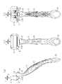
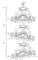
- FIG. 1 is a side view which shows the whole swing-type razor which cap-covered the razor head attached to the holder
- (b) is a front view of the swing-type razor of FIG. 1 (a)
- (c) Is a rear view of the swing razor of FIG. 1 (a).
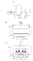
- (A) is a partial enlarged side view of FIG. 1 (a)
- (b) is a partial enlarged front view of FIG. 1 (b)
- (c) is a partial enlarged rear view of FIG. 1 (c)
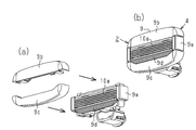
- (A) is a partial enlarged side view showing the razor head with the cap removed.
- (B) is a partial enlarged front view showing the razor head with the cap removed.
- (C) is the cap removed.
- FIG. 5 is a partially enlarged rear view showing the razor head in a state.
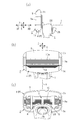
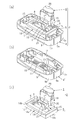
- A is a partially enlarged side sectional view showing the razor head and the head of the holder
- (b) is a partially enlarged rear view showing the razor head removed from the head of the holder
- FIG. 10 is a partially enlarged plan view showing the razor head removed from the head.
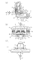
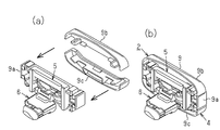
- A) is a rear perspective view showing a state in which the blade assembly, the elastic support and the connection portion are assembled to each other in the razor head removed from the head of the holder
- (b) is a blade assembly before assembly It is a back perspective view showing an attachment
- (c) is a back perspective view showing an elastic support body and a connection part before attachment.
- (A) is a front perspective view showing a blade assembly in which the upper and lower parts are separated from the middle part having a blade, and (b) is a blade assembly in which the upper and lower parts are assembled to the middle part having a blade. It is a front perspective view showing.
- (A) is a rear perspective view showing a blade assembly in which the upper portion and the lower portion are separated from the middle portion having the blade, and (b) is a blade assembly having the upper portion and the lower portion assembled to the middle portion having the blade. It is a rear perspective view showing.
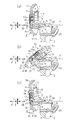
- FIG. (A) is the partial expanded sectional view which looked at the razor head which the blade assembly body is in the neutral position from the side, and (b) and (c) are the partial enlargement sides of the razor head in which the blade assembly is in the movement position.
- FIG. (A) is a partial enlarged plan sectional view showing the razor head in which the blade assembly is in the neutral position, and (b) and (c) are partial enlarged plan sections showing the razor head in which the blade assembly is in the moving position
- the swing razor shown in FIGS. 1 (a) to 1 (c) includes a holder 1, a razor head 2 and a cap 3.
- the razor head 2 comprises a blade assembly 4, an elastic support 5 and a connection 6.
- the elastic support 5 includes a support 7 and a flexible portion 8.
- the blade assembly 4 of the razor head 2 has an intermediate portion 9a, It comprises a frame portion 9 constituted by an upper portion 9 b and a lower portion 9 c.
- the upper part 9b and the lower part 9c are non-removably attached to the middle part 9a.
- a plurality of blade bodies 10 each having a cutting edge 10a are assembled to the intermediate portion 9a.
- the plurality of blades 10 are arranged in the vertical direction Z.
- the blade edge 10 a of each blade 10 is exposed on the front side of the intermediate portion 9 a and extends in the left-right direction Y. As shown in FIG.
- an uneven mounting table 11 is provided on the back side of the intermediate portion 9 a.
- a plate-like regulating unit 12 is provided below the mounting table 11.
- the restricting portion 12 is located at the central portion in the left-right direction Y of the blade assembly 4.
- the restricting portion 12 protrudes in the rearward direction XB from the rear surface of the middle portion 9a.
- a fulcrum groove portion 13 (fulcrum portion) extending in the left-right direction Y is provided between the restricting portion 12 and the mounting table portion 11.
- Shaving aids are attached to the surfaces of the upper 9 b and lower 9 c of the frame 9.
- a soft resin fin 9d is provided on the surface of the lower portion 9c so as to be able to cause wrinkles.
- the support portion 7 of the elastic support 5 of the razor head 2 is formed in a substantially U shape by the upper portion 14a, the left portion 14b (support portion), and the right portion 14c (support portion).
- the mounting unit 14 is provided.
- the connection portion 6 of the razor head 2 is disposed between the left portion 14b and the right portion 14c.
- flexible portions 8 having a rectangular plate shape in cross section are disposed.
- Each of the left portion 14 b and the right portion 14 c is provided with a continuous portion 15 (support portion) integrally formed with the flexible portion 8.
- the mounting portion 14 of the support portion 7 is non-removably attached to the mounting base portion 11 of the blade assembly 4.
- each of the left and right flexible parts 8 has an inner end 8a adjacent to the connection 6 and an outer end 8b opposite to the inner end 8a.
- the outer end 8 b of the left flexible portion 8 is adjacent to the left portion 14 b of the support 7.
- the outer end 8 b of the right flexible portion 8 is adjacent to the right portion 14 c of the support 7.
- the space between the outer ends 8b of the left and right flexible parts 8 constitutes an assumed air space S. More specifically, the assumed air space S is a space on the assumed line L connecting the outer ends 8 b of the left and right flexible portions 8 or a cylindrical air space surrounding the outer periphery of the assumed line L.
- the assumed air space S is a cylindrical air space including an extended line of the outer peripheral edge of the outer end portion 8 b having a predetermined cross-sectional shape such as a rectangular shape.
- Each flexible portion 8 has an inclined portion 16 inclined so as to approach the assumed air space S as it goes from the inner end 8 a to the outer end 8 b of the flexible portion 8.
- the distance between the inclined portions 16 of the left and right flexible portions 8 gradually increases from the inner end 8a toward the outer end 8b.
- the inclined portion 16 is inclined with respect to the assumed air space S when viewed in the front-rear direction X and the up-down direction Z.
- connection portion 6 of the razor head 2 includes a main portion 18, a plate-like tongue piece 19 (projecting piece), and a connecting cylindrical portion 20 (connected Section) and
- the main portion 18 has a continuous portion 17 integrally formed with the left and right flexible portions 8.
- the main body portion 18 is located above the restricting portion 12 of the blade assembly 4 and faces the restricting portion 12.
- the tongue piece 19 extends from the main body 18 in the forward direction XF. That is, the tongue piece 19 (projecting piece) is located on the back side of the blade assembly 4 and protrudes toward the blade assembly 4.
- the connecting cylindrical portion 20 extends from the main portion 18 in the rearward direction XB.
- the dimension of the tongue piece 19 in the left-right direction Y along the extending direction of the blade edge 10 a of the blade 10 corresponds to the width dimension of the tongue piece 19.
- the dimension of the tongue piece 19 in the front-rear direction X orthogonal to the left-right direction Y corresponds to the length dimension of the tongue piece 19.
- the dimension of the tongue piece 19 in the vertical direction Z orthogonal to both the left-right direction Y and the front-rear direction X corresponds to the thickness dimension of the tongue piece 19.
- the thickness dimension of the tongue portion 19 is set smaller than the width dimension and the length dimension of the tongue portion 19.
- the width dimension of the tongue portion 19 is set smaller than the length dimension of the tongue portion 19.
- the free end of the tongue piece 19 is provided with a fulcrum edge 21 (fulcrum) that extends in the left-right direction Y and abuts on the fulcrum groove 13 of the blade assembly 4.
- the dimension between the upper surface and the lower surface of the fulcrum edge 21 corresponds to the thickness dimension of the fulcrum edge 21.
- the upper surface of the fulcrum edge 21 is inclined so that the thickness dimension of the fulcrum edge 21 becomes smaller toward the free end.
- the fulcrum groove 13 of the blade assembly 4 and the fulcrum edge 21 of the tongue piece 19 are disposed below the cutting edge 10 a of the blade 10 and inside the assumed air space S.
- the blade assembly 4 is supported by the support portion 7 of the elastic support 5 as the fulcrum edge 21 and the fulcrum groove 13 abut each other.
- the extending direction of the blade edge 10 a of the blade 10 coincides with the left-right direction Y.
- the longitudinal direction X is orthogonal to the lateral direction Y.
- the up-down direction Z is orthogonal to both the left-right direction Y and the front-rear direction X.
- the blade assembly 4 has a neutral position on the vertical plane V defined by the longitudinal direction X and the vertical direction Z along with the deformation of the flexible portion 8. It can move so as to draw an arc-like locus from P to the longitudinal direction X.
- the blade assembly 4 moves in the moving direction XV along the arc so as to draw an arc-like locus on the vertical plane V. It can move. Then, as shown in FIGS. 8A to 8C, the blade assembly 4 can be disposed at the movement position Q by moving in the movement direction XV along with the deformation of the flexible portion 8. Further, as shown in FIGS. 9A to 9C, the blade assembly 4 is neutral on the horizontal plane H defined by the left and right direction Y and the front and back direction X along with the deformation of the flexible portion 8. It can move so as to draw an arc-like locus from the position P to the longitudinal direction X.
- the blade assembly 4 moves in the moving direction XH along the arc so as to draw an arc-like locus on the horizontal surface H It can. Then, as shown in FIGS. 9A to 9C, the blade assembly 4 can be disposed at the movement position Q by moving in the movement direction XH along with the deformation of the flexible portion 8.
- the fulcrum groove 13 of the blade assembly 4 and the fulcrum edge 21 of the tongue piece 19 are formed in an arc shape along the moving direction XV.
- the supporting point edge 21 of the tongue piece 19 is formed in an arc shape along the moving direction XH.
- the support portion 7 of the elastic support 5 and the connection portion 6 are simultaneously molded in one mold except for the continuous portions 15 and 17. Thereafter, the flexible portion 8 is formed together with the continuous portions 15 and 17, and the support portion 7 and the connection portion 6 are integrally formed by connecting the continuous portions 15 and 17 to each other.
- the holder 1 has a main body 22 which is long in the vertical direction Z, a grip 23 provided on the outer periphery of the main body 22, and an upper end of the main body 22. And a head 24 provided on the The head 24 is provided with a connecting hole 25 (connecting portion) that penetrates the head 24 in the front-rear direction X.
- An elastic engagement / disengagement portion 26 extending in the rearward direction XB is provided in the connection cylindrical portion 20 of the connection portion 6 (see FIG. 4C).
- the connecting cylindrical portion 20 is detachably inserted into the connecting hole portion 25 via the engagement by the elastic engagement / disengagement portion 26. In the inserted state, the head 24 and the connecting portion 6 are integrally continuous with each other.
- the connection cylindrical portion 20 is pulled out of the connection hole 25 by releasing the engagement by the elastic engagement / disengagement portion 26, the head 24 and the connection portion 6 are separated from each other.
- the cap 3 is removably put on the blade assembly 4 of the razor head 2 from the upper side in the vertical direction Z.
- the cap 3 has a back plate 27 facing the back side of the blade assembly 4.
- a stopper stepped portion 28 (stopper portion) is formed on the main body portion 18 of the connection portion 6 of the razor head 2.
- a stopper edge 29 is formed at the lower end of the back plate 27. The stopper edge 29 of the cap 3 is engaged with the stopper step 28 of the razor head 2.
- the cap may be configured to be detachably put on the blade assembly 4 of the razor head 2 from the lower side in the vertical direction Z.
- the main part of the blade assembly 4, the mounting portion 14 of the support portion 7 of the elastic support 5, the connection portion 6, the main portion 22 of the holder 1, and the cap 3 are made of ABS resin or polypropylene resin Etc. It is shape
- the continuous portion 15 of the support portion 7 of the elastic support 5, the flexible portion 8 of the elastic support 5, the continuous portion 17 of the connection portion 6, and the grip portion 23 of the holder 1 It is molded by a soft resin such as a styrene-based elastomer resin.
- a soft resin such as a styrene-based elastomer resin.
- an elastomer resin for forming the flexible portion 8 a material having a hardness in the range of Shore A 40 to Shore D 70 is employed.
- a material having a hardness of Shore A 90 is employed.
- FIGS. 8 (a) and 9 (a) at the neutral position P of the swing razor, the fulcrum groove 13 of the blade assembly 4 and the fulcrum edge 21 of the tongue piece 19 are in contact with each other.
- the left and right flexible parts 8 are stationary in the state of being in contact.
- the razor head 2 extends and stands along the vertical direction Z and the lateral direction Y.
- a slight gap G exists between the regulation portion 12 of the blade assembly 4 of the razor head 2 and the main portion 18 and the tongue piece 19 of the connection portion 6 of the razor head 2. It is formed.
- a swing for rotating the blade assembly 4 along the vertical plane V and a rotation of the blade assembly 4 along the horizontal plane H
- a combination of swinging can also be performed.
- the present embodiment has the following effects.
- (1) The blade assembly 4 is supported by the flexible portion 8 in the razor head 2.
- the support structure for rotatably supporting the blade assembly 4 against the biasing force of the flexible portion 8 can be simplified.
- the flexible portion 8 is provided on the back side of the blade assembly 4. Therefore, since the flexible portion 8 can be easily disposed at a position relatively close to the blade 10, the blade assembly 4 can be operated smoothly on the skin surface in use to improve the feel on the skin surface.
- the blade assembly 4 When rotating the blade assembly 4 against the biasing force of the flexible portion 8 when using the swing razor, the blade assembly 4 is a fulcrum (supporting groove 13, support edge 21) , So that the movement of the blade assembly 4 can be stabilized.
- connection portion 6 and the blade assembly 4 of the razor head 2 can support the blade assembly 4 movably with respect to the connection portion 6 (fulcrum edge 21, fulcrum groove 13) have.
- the support portions 7 of the blade assembly 4 and the elastic support 5 may be supported by the left and right flexible portions 8 by omitting their supporting points.
- you may provide several fulcrum parts other than one fulcrum part.
- the fulcrum (fulcrum edge 21 and fulcrum groove 13) is disposed inside the assumed air space S, but the fulcrum may be disposed outside the assumed air space S.
- the fulcrum edge 21 of the connecting portion 6 and the fulcrum groove 13 of the blade assembly 4 abut each other at the neutral position P and the movement position Q, respectively. That is, at both the neutral position P and the movement position Q, the blade assembly 4 is supported by the connecting portion 6 by the abutment of the fulcrum edge 21 and the fulcrum groove 13.
- the fulcrum edge 21 of the connection portion 6 and the fulcrum groove 13 of the blade assembly 4 may be in contact with each other at at least one of the neutral position P and the movement position Q. That is, at least one of the neutral position P and the movement position Q, the blade assembly 4 may be supported by the connection portion 6 by the abutment of the fulcrum edge 21 and the fulcrum groove 13.
- the fulcrum portions (fulcrum edge 21 and fulcrum groove 13) may be separated at the neutral position P, and when moving from the neutral position P to the movement position Q, the fulcrum portions may abut.
- a swing that rotates the blade assembly 4 along the vertical plane V a swing that rotates the blade assembly 4 along the horizontal surface H, and a swing that combines them. And may be able to perform only one swing.
- the plate-like tongue piece 19 may be configured to be deformable in the thickness direction (vertical direction Z). -Although the plate-like tongue piece 19 is employ
- connection part 6 of the razor head 2 and the head 24 of the holder 1 can be attached or detached via those connection parts (the connection cylinder part 20, the connection hole part 25).
- the razor head 2 may be provided integrally with the holder 1 by omitting the connecting portions.
- other connection structures may be adopted.
- the plate-shaped flexible part 8 of a cross-sectional rectangle was employ
- the flexible portion 8 having the inclined portion 16 is disposed so as to extend mainly in the left-right direction Y.
- the flexible portion 8 may be disposed so as to extend mainly in the vertical direction Z.
- the flexible portions 8 are disposed between the support 7 and the connection 6 on both sides in the left-right direction Y.
- one or three or more flexible portions 8 may be connected to the support 7 and the connection 6 It may be placed between -In the said embodiment, the flexible part 8, the continuous part 15 of the support part 7, and the continuous part 17 of the connection part 6 were shape
- the flexible portion 8, the continuous portion 15, and the continuous portion 17 may be formed in a thin plate shape without using a soft resin, or may be configured to be deformable by forming a thin hinge portion.
- the blade edge 10a of the blade 10 of the razor head 2 extends in the left-right direction Y
- the holder 1 extends in the up-down direction Z, but extends in directions other than the up-down direction Z
- the holder 1 may be arranged in the same manner.
- the shaving aid is attached to the surface of the upper portion 9b and the lower portion 9c of the frame portion 9.
- any one or the middle portion 9a, the upper portion 9b and the lower portion 9c of the frame portion 9 is used. Two or three shaving aids can be attached.
- the shaving aid attached to the surface of the upper portion 9b of the frame 9 and the shaving aid attached to the surface of the lower portion 9c of the frame 9 may have the same components as each other.
- the shaving aid attached to the surface of the upper portion 9b of the frame 9 and the shaving aid attached to the surface of the lower portion 9c of the frame 9 may have different components.
- a shaving aid with moisturizing ingredients may be provided on the surface of the upper part 9b.
- the upper part 9b and the lower part 9c to which the shaving aid is attached are irremovably attached to the middle part 9a, the upper part 9b and the lower part 9c can be replaced so that the upper part 9b and the lower part 9c can be replaced. You may attach to the intermediate part 9a so that attachment or detachment is possible.
Abstract
首振り式剃刀は、頭部(24)を有するホルダ(1)と、ホルダ(1)に取り付けられた剃刀ヘッド(2)とを備える。剃刀ヘッド(2)は、刃組付体(4)と、弾性支持体(5)と、ホルダ(1)の頭部(24)に連続する接続部(6)とを備える。弾性支持体(5)は、刃組付体(4)を支持する支持部(7)と、支持部(7)及び接続部(6)の間に位置する可撓部(8)とを備える。刃組付体(4)が弾性支持体(5)の可撓部(8)により付勢されて静止する位置は中立位置(P)である。刃組付体(4)は、中立位置(P)から可撓部(8)の付勢力に抗して移動した少なくとも一つの移動位置(Q)に移動可能である。
Description
本発明は、刃体を組み付けた剃刀ヘッドがホルダの頭部に対し弾性力に抗して移動し得る首振り式剃刀に関するものである。
特許文献1には、従来の安全剃刀が開示されている。特許文献1の安全剃刀は、柄と、刃体を有する替刃ユニットと、柄及び替刃ユニットの間に位置するジョイントとを備えている。柄は、ジョイントを枢動可能に支持する枢動軸と、ジョイントをジョイントの中立位置へ向けて付勢する弾性部材とを備えている。ジョイントは、替刃ユニットを支持するための一対のジャーナル軸を備えている。替刃ユニットは、ジョイントの一対のジャーナル軸に対応して設けられた一対のジャーナル軸受と、替刃ユニットを替刃ユニットの中立位置へ向けて付勢する弾性片とを備えている。ジョイントの一対のジャーナル軸が替刃ユニットの一対のジャーナル軸受に受容されることで、替刃ユニットは両ジャーナル軸の周りに揺動可能にジョイントに支持されている。より詳しくは、替刃ユニットは、替刃ユニットの中立位置を基準として、両ジャーナル軸の周りを、弾性片による弾性力に抗して、揺動する。さらに、替刃ユニットを支持するジョイントは、ジョイントの中立位置を基準として、枢動軸の周りを、弾性部材による弾性力に抗して、替刃ユニットとともに揺動する。
特許文献1の安全剃刀では、ジャーナル軸を中心とする揺動方向及び枢動軸を中心とする揺動方向のそれぞれに対して揺動支持構造を必要とするため、剃刀の構造が複雑になっていた。
この発明は、頭部を有するホルダと、刃体を有する剃刀ヘッドとを備える首振り式剃刀において、剃刀ヘッドをホルダの頭部に対する中立位置から弾性力に抗して移動させ得るように剃刀ヘッドをホルダの頭部に支持するための支持構造を簡単にすることを目的としている。
本発明の一態様における首振り式剃刀は、頭部を有するホルダと、前記ホルダに取り付けられた剃刀ヘッドとを備え、前記剃刀ヘッドは、刃体を有する刃組付体と、弾性支持体と、前記ホルダの前記頭部に連続する接続部とを備え、前記刃組付体は、前記刃体の刃先が露出する表側と、当該表側とは反対側の裏側とを有し、前記弾性支持体は前記裏側に位置し、前記弾性支持体は、前記刃組付体を支持する支持部と、前記支持部及び前記接続部の間に位置する可撓部とを備え、前記刃組付体が前記弾性支持体の前記可撓部により付勢されて静止する位置は中立位置であり、前記刃組付体は、前記中立位置から前記可撓部の付勢力に抗して移動した少なくとも一つの移動位置に移動可能である。
この構成によれば、ホルダに取り付けた剃刀ヘッドにおいて、刃組付体が可撓部により支持されるため、刃組付体を可撓部の付勢力に抗して中立位置に対し移動可能に支持する支持構造を簡単にすることができる。また、刃組付体の裏側に可撓部を設けたため、刃体に比較的近い位置に可撓部を配置し易くなる。よって、首振り式剃刀の使用時に肌面で刃組付体を滑らかに操作して肌面に対する感触を良くすることができる。
上記首振り式剃刀において、前記接続部及び前記刃組付体の各々は、前記接続部に対し前記刃組付体を支持する支点部を有していることが好ましい。
この構成によれば、首振り式剃刀の使用時に刃組付体を可撓部の付勢力に抗して移動させる際に、刃組付体が支点部で支えられるため、刃組付体の動きを安定させることができる。例えば、それらの支点部が刃組付体の中立位置及び移動位置でそれぞれ互いに当接する場合、中立位置及び移動位置の両位置において刃組付体が支点部同士の当接により支持されるため、接続部に対する刃組付体の移動を中立位置及び移動位置の間で安定させることができる。
この構成によれば、首振り式剃刀の使用時に刃組付体を可撓部の付勢力に抗して移動させる際に、刃組付体が支点部で支えられるため、刃組付体の動きを安定させることができる。例えば、それらの支点部が刃組付体の中立位置及び移動位置でそれぞれ互いに当接する場合、中立位置及び移動位置の両位置において刃組付体が支点部同士の当接により支持されるため、接続部に対する刃組付体の移動を中立位置及び移動位置の間で安定させることができる。
上記首振り式剃刀において、前記支持部は前記刃組付体を支持する二つの支持部のうちの一つであり、前記可撓部は二つの可撓部のうちの一つであり、前記二つの可撓部のうちの一方は前記二つの支持部のうちの一方と前記接続部との間に位置し、前記二つの可撓部のうちの他方は、前記二つの支持部のうちの他方と前記接続部との間に位置することが好ましい。
この構成によれば、各支持部と接続部との間で可撓部を安定した状態で設けることができる。
上記首振り式剃刀において、前記刃先の延在方向は左右方向と一致し、前記二つの可撓部は前記接続部に対して前記左右方向の両側に配置されていることが好ましい。
上記首振り式剃刀において、前記刃先の延在方向は左右方向と一致し、前記二つの可撓部は前記接続部に対して前記左右方向の両側に配置されていることが好ましい。
この構成によれば、前後方向における剃刀ヘッドの寸法を低減できるため、剃刀ヘッドをコンパクトにすることができる。
上記首振り式剃刀において、前記刃先の延在方向は左右方向と一致し、前記接続部の前記支点部と前記刃組付体の前記支点部とは、前記左右方向に対し直交する上下方向において前記刃先の下方に配置されていることが好ましい。
上記首振り式剃刀において、前記刃先の延在方向は左右方向と一致し、前記接続部の前記支点部と前記刃組付体の前記支点部とは、前記左右方向に対し直交する上下方向において前記刃先の下方に配置されていることが好ましい。
この構成によれば、支点部の上方で刃組付体及び刃体に付与される力により、刃組付体を容易に移動させることができる。
上記首振り式剃刀において、前記接続部は、前記刃組付体の前記裏側に位置するとともに当該刃組付体に向けて突出して自由端部を有する突片部を有し、前記接続部の前記支点部は前記自由端部に形成されていることが好ましい。
上記首振り式剃刀において、前記接続部は、前記刃組付体の前記裏側に位置するとともに当該刃組付体に向けて突出して自由端部を有する突片部を有し、前記接続部の前記支点部は前記自由端部に形成されていることが好ましい。
この構成によれば、支点部を容易に形成することができる。
上記首振り式剃刀において、前記刃組付体は、前記中立位置と前記移動位置との間で弧状の軌跡を描くように弧に沿った移動方向に移動することが好ましい。
上記首振り式剃刀において、前記刃組付体は、前記中立位置と前記移動位置との間で弧状の軌跡を描くように弧に沿った移動方向に移動することが好ましい。
この構成によれば、支点部の周りに刃組付体を容易に移動させることができる。
上記首振り式剃刀において、前記接続部の前記支点部は、前記移動方向に沿う弧形状を有していることが好ましい。
上記首振り式剃刀において、前記接続部の前記支点部は、前記移動方向に沿う弧形状を有していることが好ましい。
この構成によれば、刃組付体の支点部に対する接続部の支点部の当接位置が刃組付体の移動に伴い変化するため、支点部同士の接触抵抗が低減される。よって、首振り式剃刀の使用時に刃組付体が滑らかに移動するため、肌面に対する感触を良くすることができる。
上記首振り式剃刀において、各可撓部は、前記接続部に隣接する内端部と、前記二つの支持部のうちその可撓部に隣接する一方の支持部に隣接する外端部とを備え、両可撓部の両外端部の間の空間は想定空域を構成し、前記接続部の前記支点部と前記刃組付体の前記支点部とは、前記想定空域の内側に配置されていることが好ましい。
この構成によれば、両可撓部の両外端部の間の想定空域の内側に支点部が配置されているため、刃組付体を可撓部の付勢力に抗して移動させる際の可撓部の動きが安定する。よって、刃組付体を滑らかに移動させることができる。
上記首振り式剃刀において、前記刃組付体は複数の移動方向に移動可能であり、少なくとも一つの前記移動位置は複数の移動位置であり、前記刃組付体は、前記中立位置と各移動位置との間で複数の前記移動方向のうちの少なくとも一つの移動方向に移動することが好ましい。
この構成によれば、刃組付体が複数の移動方向に移動するため、首振り式剃刀の剃り味を高めることができる。例えば、接続部の支点部と刃組付体の支点部とが、刃組付体の各移動位置で互いに当接すれば、各移動位置において、刃組付体が、支点部同士の当接により支持されるため、接続部に対する刃組付体の移動を各移動位置で安定させることができる。
上記首振り式剃刀において、前記刃先の延在方向は左右方向と一致し、前記左右方向に直交する方向は前後方向であり、前記左右方向及び前記前後方向の両方向に直交する方向は上下方向であり、前記前後方向及び前記上下方向は鉛直面を規定し、前記左右方向及び前後方向は水平面を規定し、複数の前記移動位置は第1の移動位置及び第2の移動位置を含み、前記刃組付体は、前記中立位置と前記第1の移動位置との間では、前記鉛直面上で弧状の軌跡を描くように弧に沿った移動方向に移動し、前記刃組付体は、前記中立位置と前記第2の移動位置との間では、前記水平面上で弧状の軌跡を描くように弧に沿った移動方向に移動することが好ましい。
この構成によれば、刃組付体が鉛直面上の移動方向と水平面上の移動方向とで弧状の軌跡を描くように移動するため、首振り式剃刀の剃り味を高めることができる。
上記首振り式剃刀において、各可撓部は、前記接続部に隣接する内端部と、前記二つの支持部のうちその可撓部に隣接する一方の支持部に隣接する外端部と、前記内端部及び前記外端部の間に位置する傾斜部とを備え、両可撓部の両外端部の間の空間は想定空域を構成し、各可撓部の前記傾斜部は、その可撓部の前記内端部からその可撓部の前記外端部に向かうに従い前記想定空域に接近するように傾斜していることが好ましい。
上記首振り式剃刀において、各可撓部は、前記接続部に隣接する内端部と、前記二つの支持部のうちその可撓部に隣接する一方の支持部に隣接する外端部と、前記内端部及び前記外端部の間に位置する傾斜部とを備え、両可撓部の両外端部の間の空間は想定空域を構成し、各可撓部の前記傾斜部は、その可撓部の前記内端部からその可撓部の前記外端部に向かうに従い前記想定空域に接近するように傾斜していることが好ましい。
この構成によれば、各可撓部における内端部と外端部との間の長さを傾斜部により長くして可撓部を撓み易くすることができる。
上記首振り式剃刀において、両可撓部同士の間隔は前記内端部から前記外端部に向かうに従い次第に大きくなっていることが好ましい。
上記首振り式剃刀において、両可撓部同士の間隔は前記内端部から前記外端部に向かうに従い次第に大きくなっていることが好ましい。
この構成によれば、両可撓部に傾斜部を容易に形成することができる。
上記首振り式剃刀において、前記弾性支持体の各支持部は、前記二つの可撓部のうちその支持部に隣接する一方の可撓部と一体成形された連続部を有し、前記接続部は、両可撓部と一体成形された連続部を有していることが好ましい。
上記首振り式剃刀において、前記弾性支持体の各支持部は、前記二つの可撓部のうちその支持部に隣接する一方の可撓部と一体成形された連続部を有し、前記接続部は、両可撓部と一体成形された連続部を有していることが好ましい。
この構成によれば、連続部を介して弾性支持体の両支持部及び剃刀ヘッドの接続部に両可撓部を容易に取り付けることができる。
上記首振り式剃刀において、前記剃刀ヘッドの前記接続部と前記ホルダの前記頭部との各々は、前記頭部に対し前記接続部を着脱可能に連結する連結部を有していることが好ましい。
上記首振り式剃刀において、前記剃刀ヘッドの前記接続部と前記ホルダの前記頭部との各々は、前記頭部に対し前記接続部を着脱可能に連結する連結部を有していることが好ましい。
この構成によれば、連結部を介してホルダに対して剃刀ヘッドを着脱させることができる。
本発明によれば、首振り式剃刀において、剃刀ヘッドをホルダの頭部に対する中立位置から弾性力に抗して移動させ得るように剃刀ヘッドをホルダの頭部に支持するための支持構造を簡単にすることができる。
以下、本発明の一実施形態にかかる首振り式剃刀について図面を参照して説明する。
図1(a)~図1(c)に示す首振り式剃刀は、ホルダ1、剃刀ヘッド2、及びキャップ3を備えている。剃刀ヘッド2は刃組付体4、弾性支持体5、及び接続部6を備えている。弾性支持体5は支持部7及び可撓部8を備えている。
図1(a)~図1(c)に示す首振り式剃刀は、ホルダ1、剃刀ヘッド2、及びキャップ3を備えている。剃刀ヘッド2は刃組付体4、弾性支持体5、及び接続部6を備えている。弾性支持体5は支持部7及び可撓部8を備えている。
図3(a)~図3(c)、図6(a)(b)、及び図7(a)(b)に示すように、剃刀ヘッド2の刃組付体4は、中間部9a、上部9b、及び下部9cにより構成された枠部9を備えている。上部9b及び下部9cは中間部9aに対し離脱不能に取り付けられている。中間部9aには各々が刃先10aを有する複数の刃体10が組み付けられている。複数の刃体10は上下方向Zへ並べられている。各刃体10の刃先10aは、中間部9aの表側に露出しており、かつ左右方向Yへ延在している。図5(b)に示すように、枠部9内において、中間部9aの裏側には凹凸状の載置台部11が設けられている。載置台部11の下方には板状の規制部12が設けられている。規制部12は刃組付体4における左右方向Yの中央部に位置している。規制部12は中間部9aの後面から後向きXBへ突出している。規制部12と載置台部11との間には左右方向Yへ延在する支点溝部13(支点部)が設けられている。枠部9の上部9b及び下部9cの表面にはシェービングエイドが取着されている。さらに、下部9cの表面には髭を起こすことができるように軟質樹脂製のフィン9dが設けられている。
図5(c)に示すように、剃刀ヘッド2の弾性支持体5の支持部7は、上部14a、左部14b(支持部)、及び右部14c(支持部)により略U字形状に形成された載置部14を備えている。剃刀ヘッド2の接続部6は、左部14b及び右部14cの間に配置されている。接続部6と左部14bとの間及び接続部6と右部14cとの間には断面矩形の板状をなす可撓部8がそれぞれ配置されている。左部14b及び右部14cの各々には、可撓部8と一体成形された連続部15(支持部)が設けられている。支持部7の載置部14は刃組付体4の載置台部11に対し離脱不能に取り付けられている。図4(b)に示すように、左右両可撓部8の各々は、接続部6に隣接する内端部8aと、内端部8aとは反対側の外端部8bとを有している。詳しくは、左側の可撓部8の外端部8bは支持部7の左部14bに隣接している。右側の可撓部8の外端部8bは支持部7の右部14cに隣接している。図9(a)~図9(c)に示すように、左右両可撓部8の両外端部8bの間の空間は想定空域Sを構成している。詳しくは、想定空域Sは、左右両可撓部8の外端部8b同士を結ぶ想定線L上の空間、または、その想定線Lの外周を囲う筒状空域である。換言すれば、想定空域Sは、矩形状などの所定断面形状を有する外端部8bの外周縁の延長線を含む筒状空域である。各可撓部8は、その可撓部8の内端部8aから外端部8bに向かうに従い想定空域Sに接近するように傾斜する傾斜部16を有している。左右両可撓部8の傾斜部16同士の間隔は内端部8aから外端部8bに向かうに従い次第に大きくなっている。傾斜部16は前後方向X及び上下方向Zで見て共に想定空域Sに対し傾斜している。
図5(a)及び図5(c)に示すように、剃刀ヘッド2の接続部6は、主体部18と、板状の舌片部19(突片部)と、連結筒部20(連結部)とを備えている。主体部18は、左右両可撓部8と一体成形された連続部17を有している。図4(a)に示すように、主体部18は、刃組付体4の規制部12の上方に位置し、かつ当該規制部12に面している。舌片部19は、主体部18から前向きXFに延在している。すなわち、舌片部19(突片部)は刃組付体4の裏側に位置し、かつ刃組付体4に向けて突出している。連結筒部20は、主体部18から後向きXBに延在している。刃体10の刃先10aの延在方向に沿う左右方向Yにおける舌片部19の寸法は、舌片部19の幅寸法に対応する。左右方向Yに対し直交する前後方向Xにおける舌片部19の寸法は、舌片部19の長さ寸法に対応する。左右方向Y及び前後方向Xの両方向に直交する上下方向Zにおける舌片部19の寸法は、舌片部19の厚さ寸法に対応する。このとき、舌片部19の厚さ寸法は舌片部19の幅寸法及び長さ寸法よりも小さく設定されている。また、舌片部19の幅寸法は、舌片部19の長さ寸法より小さく設定されている。舌片部19の自由端部には、左右方向Yに延在し、かつ刃組付体4の支点溝部13に当接する支点縁部21(支点部)が設けられている。支点縁部21の上面と下面との間の寸法は、支点縁部21の厚さ寸法に対応する。支点縁部21の上面は、支点縁部21の厚さ寸法が自由端部に向かうに従い小さくなるように傾斜している。刃組付体4の支点溝部13と舌片部19の支点縁部21とは刃体10の刃先10aよりも下側かつ想定空域Sの内側に配置されている。支点縁部21及び支点溝部13が互いに当接することにより、刃組付体4が弾性支持体5の支持部7に支持されている。
刃体10の刃先10aの延在方向は左右方向Yに一致する。前後方向Xは左右方向Yに直交する。上下方向Zは左右方向Y及び前後方向Xの両方向に直交する。刃組付体4は、図8(a)~図8(c)に示すように、可撓部8の変形に伴い、前後方向X及び上下方向Zにより規定される鉛直面V上で中立位置Pから前後方向Xへ弧状の軌跡を描くように移動し得る。すなわち、このときの刃組付体4の移動方向を移動方向XVと称すると、刃組付体4は、鉛直面V上で、弧状の軌跡を描くように、弧に沿った移動方向XVに移動し得る。そして、刃組付体4は、図8(a)~図8(c)に示すように、可撓部8の変形に伴い移動方向XVに移動することで、移動位置Qに配置され得る。また、刃組付体4は、図9(a)~図9(c)に示すように、可撓部8の変形に伴い、左右方向Y及び前後方向Xにより規定される水平面H上で中立位置Pから前後方向Xへ弧状の軌跡を描くように移動し得る。すなわち、このときの刃組付体4の移動方向を移動方向XHと称すると、刃組付体4は、水平面H上で、弧状の軌跡を描くように、弧に沿った移動方向XHに移動し得る。そして、刃組付体4は、図9(a)~図9(c)に示すように、可撓部8の変形に伴い移動方向XHに移動することで、移動位置Qに配置され得る。刃組付体4の支点溝部13及び舌片部19の支点縁部21は、移動方向XVに沿う弧形状に形成されている。舌片部19の支点縁部21は、移動方向XHに沿う弧形状に形成されている。
剃刀ヘッド2においては、弾性支持体5の支持部7と接続部6とを連続部15,17を除いて一つの型内で同時に成形する。その後、連続部15,17とともに可撓部8を成形して、支持部7と接続部6とを連続部15,17で互いに繋いで一体的に形成する。
図1(a)~図1(c)に示すように、ホルダ1は、上下方向Zに長い主体部22と、主体部22の外周に設けられた把持部23と、主体部22の上端部に設けられた頭部24とを備えている。頭部24には当該頭部24を前後方向Xへ貫通する連結孔部25(連結部)が設けられている。接続部6の連結筒部20には後向きXBに延在する弾性係脱部26が設けられている(図4(c)参照)。弾性係脱部26による係合を介して連結筒部20が連結孔部25に着脱可能に挿着されている。その挿着状態では、頭部24と接続部6とが互いに一体的に連続する。弾性係脱部26による係合を解除して連結筒部20を連結孔部25から引き抜くと、頭部24及び接続部6が互いに分離される。
図1(a)~図2(c)に示すように、キャップ3は、剃刀ヘッド2の刃組付体4に上下方向Zの上側から着脱可能に被せられている。図4(a)に示すように、キャップ3は刃組付体4の裏側に面する裏板部27を有している。剃刀ヘッド2の接続部6の主体部18上にはストッパ段部28(ストッパ部)が形成されている。裏板部27の下端部にはストッパ縁部29(ストッパ部)が形成されている。そして、キャップ3のストッパ縁部29が剃刀ヘッド2のストッパ段部28に係入されている。なお、剃刀ヘッド2の刃組付体4に上下方向Zの下側から着脱可能に被せられるようにキャップを構成してもよい。
ちなみに、刃組付体4の主要部と、弾性支持体5の支持部7の載置部14と、接続部6と、ホルダ1の主体部22と、キャップ3とは、ABS樹脂やポリプロピレン樹脂などの硬質樹脂により成形されている。また、弾性支持体5の支持部7の連続部15と、弾性支持体5の可撓部8と、接続部6の連続部17と、ホルダ1の把持部23とは、ポリエステル系エラストマー樹脂やスチレン系エラストマー樹脂などの軟質樹脂により成形されている。可撓部8を形成するためのエラストマー樹脂としては、ショアA40~ショアD70の範囲の硬度を有する材料が採用される。例えば、可撓部8を形成するためのエラストマー樹脂としては、ショアA90の硬度を有する材料が採用される。
次に、首振り式剃刀の使用態様について述べる。
図8(a)及び図9(a)に示すように、首振り式剃刀の中立位置Pにおいては、刃組付体4の支点溝部13と舌片部19の支点縁部21とが互いに当接した状態で左右両可撓部8が静止している。中立位置Pにおいては、剃刀ヘッド2が上下方向Z及び左右方向Yに沿うように延びて静止している。図8(a)に示すように、剃刀ヘッド2の刃組付体4の規制部12と剃刀ヘッド2の接続部6の主体部18及び舌片部19との間には若干の隙間Gが形成されている。
図8(a)及び図9(a)に示すように、首振り式剃刀の中立位置Pにおいては、刃組付体4の支点溝部13と舌片部19の支点縁部21とが互いに当接した状態で左右両可撓部8が静止している。中立位置Pにおいては、剃刀ヘッド2が上下方向Z及び左右方向Yに沿うように延びて静止している。図8(a)に示すように、剃刀ヘッド2の刃組付体4の規制部12と剃刀ヘッド2の接続部6の主体部18及び舌片部19との間には若干の隙間Gが形成されている。
中立位置Pに配置された刃組付体4の上部が後向きXBに押されると、図8(b)に示すように、支点溝部13と支点縁部21とが当接部CVで互いに当接しながら、左右両可撓部8が変形する。その結果、刃組付体4の上部が弾性支持体5の支持部7とともに後向きXBに当接部CVの周りに鉛直面Vに沿って回動する。この回動により刃組付体4が弾性支持体5の支持部7とともに傾き、刃組付体4が移動位置Q(第1の移動位置)で停止する。刃組付体4の規制部12は接続部6の主体部18及び舌片部19から下方へ離間して隙間Gが広げられる。刃組付体4は弾性支持体5の支持部7が接続部6に当接するまで回動し得る。
中立位置Pに配置された刃組付体4の下部が後向きXBに押されると、図8(c)に示すように、支点溝部13と支点縁部21とが当接部CVで互いに当接しながら、左右両可撓部8が変形する。その結果、刃組付体4の下部が弾性支持体5の支持部7とともに後向きXBに当接部CVの周りに鉛直面Vに沿って回動する。この回動により刃組付体4が弾性支持体5の支持部7とともに傾き、刃組付体4が移動位置Q(第1の移動位置)で停止する。刃組付体4は規制部12が接続部6に当接するまで隙間Gの範囲で回動し得る。すなわち、移動方向XVは、当接部CVを中心とする弧に沿う方向に対応する。
中立位置Pに配置された刃組付体4の左部が後向きXBに押されると、図9(b)に示すように、支点溝部13と支点縁部21とが互いに当接しながら、左右両可撓部8が変形する。その結果、刃組付体4の左部が弾性支持体5の支持部7とともに後向きXBに支点縁部21の後方の仮想位置CHの周りに水平面Hに沿って回動する。この回動により刃組付体4が弾性支持体5の支持部7とともに傾き、刃組付体4が移動位置Q(第2の移動位置)で停止する。刃組付体4は接続部6に当接するまで回動し得る。
中立位置Pに配置された刃組付体4の右部が後向きXBに押されると、図9(c)に示すように、支点溝部13と支点縁部21とが互いに当接しながら、左右両可撓部8が変形する。その結果、刃組付体4の右部が弾性支持体5の支持部7とともに後向きXBに仮想位置CHの周りに水平面Hに沿って回動する。この回動により刃組付体4が弾性支持体5の支持部7とともに傾き、刃組付体4が移動位置Q(第2の移動位置)で停止する。刃組付体4は接続部6に当接するまで回動し得る。すなわち、移動方向XHは、仮想位置CHを中心とする弧に沿う方向に対応する。
図示しないが、刃組付体4を鉛直面Vに沿って回動させる首振り(図8(b)及び図8(c)参照)と、刃組付体4を水平面Hに沿って回動させる首振り(図9(b)及び図9(c)参照)とを組み合わせた首振りも行うことができる。
本実施形態は下記の効果を有する。
(1) 剃刀ヘッド2において刃組付体4を可撓部8により支持した。よって、刃組付体4を可撓部8の付勢力に抗して回動可能に支持する支持構造を簡単にすることができる。
(1) 剃刀ヘッド2において刃組付体4を可撓部8により支持した。よって、刃組付体4を可撓部8の付勢力に抗して回動可能に支持する支持構造を簡単にすることができる。
(2) 刃組付体4の裏側に可撓部8を設けた。よって、刃体10に比較的近い位置に可撓部8を配置し易くなるため、使用時に肌面で刃組付体4を滑らかに操作して肌面に対する感触を良くすることができる。
(3) 首振り式剃刀の使用時に刃組付体4を可撓部8の付勢力に抗して回動させる際、刃組付体4が支点部(支持溝部13、支持縁部21)で支えられるため、刃組付体4の動きを安定させることができる。
前記実施形態を例えば下記のように変更してもよい。
・ 前記実施形態において、剃刀ヘッド2の接続部6と刃組付体4とは、接続部6に対し刃組付体4を移動可能に支え得る支点部(支点縁部21、支点溝部13)を有している。しかし、それらの支点部を省略して左右両可撓部8により刃組付体4及び弾性支持体5の支持部7を支えてもよい。また、一つの支点部以外に、複数の支点部を設けてもよい。
・ 前記実施形態において、剃刀ヘッド2の接続部6と刃組付体4とは、接続部6に対し刃組付体4を移動可能に支え得る支点部(支点縁部21、支点溝部13)を有している。しかし、それらの支点部を省略して左右両可撓部8により刃組付体4及び弾性支持体5の支持部7を支えてもよい。また、一つの支点部以外に、複数の支点部を設けてもよい。
・ 前記実施形態では、支点部(支点縁部21、支点溝部13)を想定空域Sの内側に配置したが、支点部を想定空域Sの外側に配置してもよい。
・ 前記実施形態において、接続部6の支点縁部21と刃組付体4の支点溝部13とは、中立位置P及び移動位置Qでそれぞれ互いに当接する。すなわち、中立位置P及び移動位置Qの両位置において、刃組付体4は支点縁部21及び支点溝部13の当接により接続部6に支持される。しかし、接続部6の支点縁部21と刃組付体4の支点溝部13とは、中立位置Pと移動位置Qとのうち少なくとも一方で互いに当接すればよい。すなわち、中立位置P及び移動位置Qの少なくとも一方において、刃組付体4は支点縁部21及び支点溝部13の当接により接続部6に支持されればよい。例えばそれらの支点部(支点縁部21、支点溝部13)を中立位置Pで離間させ、中立位置Pから移動位置Qに移動する際にそれらの支点部を当接させるようにしてもよい。
・ 前記実施形態において、接続部6の支点縁部21と刃組付体4の支点溝部13とは、中立位置P及び移動位置Qでそれぞれ互いに当接する。すなわち、中立位置P及び移動位置Qの両位置において、刃組付体4は支点縁部21及び支点溝部13の当接により接続部6に支持される。しかし、接続部6の支点縁部21と刃組付体4の支点溝部13とは、中立位置Pと移動位置Qとのうち少なくとも一方で互いに当接すればよい。すなわち、中立位置P及び移動位置Qの少なくとも一方において、刃組付体4は支点縁部21及び支点溝部13の当接により接続部6に支持されればよい。例えばそれらの支点部(支点縁部21、支点溝部13)を中立位置Pで離間させ、中立位置Pから移動位置Qに移動する際にそれらの支点部を当接させるようにしてもよい。
・ 前記実施形態では、刃組付体4を鉛直面Vに沿って回動させる首振りと、刃組付体4を水平面Hに沿って回動させる首振りと、それらを互いに組み合わせた首振りとを行うことができるが、いずれか一つの首振りのみを行うことができるようにしてもよい。
・ 板状の舌片部19を厚み方向(上下方向Z)に変形可能に構成してもよい。
・ 前記実施形態では、板状の舌片部19を採用しているが、舌片部19の代わりに棒状の突片部を採用してもよい。その際、突片部の先端部に半球状の支点部を形成してもよい。
・ 前記実施形態では、板状の舌片部19を採用しているが、舌片部19の代わりに棒状の突片部を採用してもよい。その際、突片部の先端部に半球状の支点部を形成してもよい。
・ 前記実施形態では、剃刀ヘッド2の接続部6とホルダ1の頭部24とをそれらの連結部(連結筒部20、連結孔部25)を介して着脱させることができる。しかし、それらの連結部を省略して剃刀ヘッド2をホルダ1に対し一体的に設けてもよい。また、接続部6と頭部24とにおいて、着脱可能な凹凸関係を逆にした連結構造を採用してもよい。また、他の連結構造を採用してもよい。
・ 前記実施形態では、断面矩形の板状の可撓部8を採用したが、円形、三角形、T字形などの断面形状を有する可撓部を採用してもよい。
・ 前記実施形態では、傾斜部16を有する可撓部8を主に左右方向Yに延在するように配置した。しかし、主に上下方向Zに延在するように可撓部8を配置してもよい。
・ 前記実施形態では、傾斜部16を有する可撓部8を主に左右方向Yに延在するように配置した。しかし、主に上下方向Zに延在するように可撓部8を配置してもよい。
・ 前記実施形態では、左右方向Yの両側で両支持部7と接続部6との間に可撓部8を配置したが、一または三以上の可撓部8を支持部7と接続部6との間に配置してもよい。
・ 前記実施形態では、可撓部8、支持部7の連続部15、及び接続部6の連続部17を軟質樹脂により成形した。しかし、これら可撓部8、連続部15、及び連続部17を軟質樹脂を用いないで薄板状に形成したり薄肉ヒンジ部を形成したりして変形可能に構成してもよい。
・ 前記実施形態では、可撓部8、支持部7の連続部15、及び接続部6の連続部17を軟質樹脂により成形した。しかし、これら可撓部8、連続部15、及び連続部17を軟質樹脂を用いないで薄板状に形成したり薄肉ヒンジ部を形成したりして変形可能に構成してもよい。
・ 前記実施形態では、剃刀ヘッド2の刃体10の刃先10aが左右方向Yに延在し、かつホルダ1が上下方向Zに延在しているが、上下方向Z以外の方向に延在するようにホルダ1を配置してもよい。
・ 前記実施形態では、枠部9の上部9b及び下部9cの表面にシェービングエイドが取着されているが、枠部9の中間部9aと上部9bと下部9cとのうち、任意の一つまたは二つまたは三つにシェービングエイドを取着することができる。
・ 枠部9の上部9bの表面に取着するシェービングエイドと枠部9の下部9cの表面に取着するシェービングエイドとは、互いに同じ成分を有するものであってもよい。枠部9の上部9bの表面に取着するシェービングエイドと枠部9の下部9cの表面に取着するシェービングエイドとは、互いに異なる成分を有するものであってもよい。保湿性成分を有するシェービングエイドを上部9bの表面に設けてもよい。
・ 前記実施形態では、シェービングエイドが取着された上部9b及び下部9cが中間部9aに対し離脱不能に取り付けられているが、上部9b及び下部9cを交換し得るように上部9b及び下部9cを中間部9aに対し着脱可能に取り付けてもよい。
1…ホルダ、2…剃刀ヘッド、4…刃組付体、5…弾性支持体、6…接続部、7…支持部、8…可撓部、10…刃体、10a…刃体の刃先、13…支点溝部(支点部)、14b…載置部の左部(支持部)、14c…載置部の右部(支持部)、15…可撓部の連続部(支持部)、19…舌片部(突片部)、21…支点縁部(支点部)、24…ホルダの頭部、P…中立位置、Q…移動位置(第1及び第2の移動位置)、X…前後方向、Y…左右方向、Z…上下方向。
Claims (15)
- 頭部を有するホルダと、前記ホルダに取り付けられた剃刀ヘッドとを備え、
前記剃刀ヘッドは、刃体を有する刃組付体と、弾性支持体と、前記ホルダの前記頭部に連続する接続部とを備え、
前記刃組付体は、前記刃体の刃先が露出する表側と、当該表側とは反対側の裏側とを有し、
前記弾性支持体は前記裏側に位置し、
前記弾性支持体は、前記刃組付体を支持する支持部と、前記支持部及び前記接続部の間に位置する可撓部とを備え、
前記刃組付体が前記弾性支持体の前記可撓部により付勢されて静止する位置は中立位置であり、
前記刃組付体は、前記中立位置から前記可撓部の付勢力に抗して移動した少なくとも一つの移動位置に移動可能である
ことを特徴とする首振り式剃刀。 - 前記接続部及び前記刃組付体の各々は、前記接続部に対し前記刃組付体を支持する支点部を有していることを特徴とする請求項1に記載の首振り式剃刀。
- 前記支持部は前記刃組付体を支持する二つの支持部のうちの一つであり、
前記可撓部は二つの可撓部のうちの一つであり、
前記二つの可撓部のうちの一方は前記二つの支持部のうちの一方と前記接続部との間に位置し、
前記二つの可撓部のうちの他方は、前記二つの支持部のうちの他方と前記接続部との間に位置する
ことを特徴とする請求項2に記載の首振り式剃刀。 - 前記刃先の延在方向は左右方向と一致し、
前記二つの可撓部は前記接続部に対して前記左右方向の両側に配置されている
ことを特徴とする請求項3に記載の首振り式剃刀。 - 前記刃先の延在方向は左右方向と一致し、
前記接続部の前記支点部と前記刃組付体の前記支点部とは、前記左右方向に対し直交する上下方向において前記刃先の下方に配置されていることを特徴とする請求項2~4のうちいずれか一項に記載の首振り式剃刀。 - 前記接続部は、前記刃組付体の前記裏側に位置するとともに当該刃組付体に向けて突出して自由端部を有する突片部を有し、
前記接続部の前記支点部は前記自由端部に形成されている
ことを特徴とする請求項2~5のうちいずれか一項に記載の首振り式剃刀。 - 前記刃組付体は、前記中立位置と前記移動位置との間で弧状の軌跡を描くように弧に沿った移動方向に移動する請求項2~6のうちいずれか一項に記載の首振り式剃刀。
- 前記接続部の前記支点部は、前記移動方向に沿う弧形状を有していることを特徴とする請求項7に記載の首振り式剃刀。
- 各可撓部は、前記接続部に隣接する内端部と、前記二つの支持部のうちその可撓部に隣接する一方の支持部に隣接する外端部とを備え、
両可撓部の両外端部の間の空間は想定空域を構成し、
前記接続部の前記支点部と前記刃組付体の前記支点部とは、前記想定空域の内側に配置されている
ことを特徴とする請求項3または請求項4に記載の首振り式剃刀。 - 前記刃組付体は複数の移動方向に移動可能であり、
少なくとも一つの前記移動位置は複数の移動位置であり、
前記刃組付体は、前記中立位置と各移動位置との間で複数の前記移動方向のうちの少なくとも一つの移動方向に移動する
ことを特徴とする請求項2~9のうちいずれか一項に記載の首振り式剃刀。 - 前記刃先の延在方向は左右方向と一致し、
前記左右方向に直交する方向は前後方向であり、
前記左右方向及び前記前後方向の両方向に直交する方向は上下方向であり、
前記前後方向及び前記上下方向は鉛直面を規定し、
前記左右方向及び前後方向は水平面を規定し、
複数の前記移動位置は第1の移動位置及び第2の移動位置を含み、
前記刃組付体は、前記中立位置と前記第1の移動位置との間では、前記鉛直面上で弧状の軌跡を描くように弧に沿った移動方向に移動し、
前記刃組付体は、前記中立位置と前記第2の移動位置との間では、前記水平面上で弧状の軌跡を描くように弧に沿った移動方向に移動する
ことを特徴とする請求項10に記載の首振り式剃刀。 - 各可撓部は、前記接続部に隣接する内端部と、前記二つの支持部のうちその可撓部に隣接する一方の支持部に隣接する外端部と、前記内端部及び前記外端部の間に位置する傾斜部とを備え、
両可撓部の両外端部の間の空間は想定空域を構成し、
各可撓部の前記傾斜部は、その可撓部の前記内端部からその可撓部の前記外端部に向かうに従い前記想定空域に接近するように傾斜している
ことを特徴とする請求項3、4、及び9のうちいずれか一項に記載の首振り式剃刀。 - 両可撓部同士の間隔は前記内端部から前記外端部に向かうに従い次第に大きくなっていることを特徴とする請求項12に記載の首振り式剃刀。
- 前記弾性支持体の各支持部は、前記二つの可撓部のうちその支持部に隣接する一方の可撓部と一体成形された連続部を有し、
前記接続部は、両可撓部と一体成形された連続部を有している
ことを特徴とする請求項3、4、9、12、及び13のうちいずれか一項に記載の首振り式剃刀。 - 前記剃刀ヘッドの前記接続部と前記ホルダの前記頭部との各々は、前記頭部に対し前記接続部を着脱可能に連結する連結部を有していることを特徴とする請求項1~14のうちいずれか一項に記載の首振り式剃刀。
Priority Applications (3)
| Application Number | Priority Date | Filing Date | Title |
|---|---|---|---|
| CN201880048770.XA CN110944812B (zh) | 2017-07-24 | 2018-07-24 | 摇头式剃刀 |
| US16/632,612 US11247358B2 (en) | 2017-07-24 | 2018-07-24 | Pivotal neck razor |
| EP18837518.2A EP3659761B1 (en) | 2017-07-24 | 2018-07-24 | Oscillating razor |
Applications Claiming Priority (2)
| Application Number | Priority Date | Filing Date | Title |
|---|---|---|---|
| JP2017-142761 | 2017-07-24 | ||
| JP2017142761A JP6755836B2 (ja) | 2017-07-24 | 2017-07-24 | 首振り式剃刀 |
Publications (1)
| Publication Number | Publication Date |
|---|---|
| WO2019022043A1 true WO2019022043A1 (ja) | 2019-01-31 |
Family
ID=65040672
Family Applications (1)
| Application Number | Title | Priority Date | Filing Date |
|---|---|---|---|
| PCT/JP2018/027611 WO2019022043A1 (ja) | 2017-07-24 | 2018-07-24 | 首振り式剃刀 |
Country Status (5)
| Country | Link |
|---|---|
| US (1) | US11247358B2 (ja) |
| EP (1) | EP3659761B1 (ja) |
| JP (1) | JP6755836B2 (ja) |
| CN (1) | CN110944812B (ja) |
| WO (1) | WO2019022043A1 (ja) |
Cited By (1)
| Publication number | Priority date | Publication date | Assignee | Title |
|---|---|---|---|---|
| US20210245380A1 (en) * | 2018-07-18 | 2021-08-12 | Bic Violex S.A. | Shaving blade assemblies |
Families Citing this family (2)
| Publication number | Priority date | Publication date | Assignee | Title |
|---|---|---|---|---|
| KR102231870B1 (ko) * | 2019-07-08 | 2021-03-25 | 주식회사 도루코 | 카트리지 커넥터 및 이를 이용한 면도기 조립체 |
| JP2022043782A (ja) * | 2020-09-04 | 2022-03-16 | 株式会社貝印刃物開発センター | ハンドル屈曲剃刀 |
Citations (5)
| Publication number | Priority date | Publication date | Assignee | Title |
|---|---|---|---|---|
| JPH0422388A (ja) | 1990-05-18 | 1992-01-27 | Kaijirushi Hamono Kaihatsu Center:Kk | 安全かみそり |
| JP2000300870A (ja) * | 1999-04-21 | 2000-10-31 | Warner Lambert Co | カミソリカートリッジ |
| JP2001510720A (ja) * | 1997-07-22 | 2001-08-07 | ザ ジレット カンパニー | 安全かみそり |
| US20030213130A1 (en) * | 2002-05-16 | 2003-11-20 | Motta Vincent C. | Razor cartridge mounting structure |
| WO2014073500A1 (ja) * | 2012-11-06 | 2014-05-15 | 株式会社 貝印刃物開発センター | 剃刀 |
Family Cites Families (26)
| Publication number | Priority date | Publication date | Assignee | Title |
|---|---|---|---|---|
| US1455751A (en) * | 1922-07-06 | 1923-05-15 | Hartman Harry Buxton | Safety razor |
| US4152828A (en) * | 1978-03-29 | 1979-05-08 | Lund Lloyd W | Razor having variable angle and tilt of its blade |
| DE8903182U1 (ja) * | 1989-03-15 | 1989-05-03 | Wilkinson Sword Gmbh, 5650 Solingen, De | |
| AR244587A1 (es) | 1989-11-17 | 1993-11-30 | Warner Lambert Co | Conjunto afeitador de seguridad movible angularmente |
| US5050301A (en) * | 1990-09-19 | 1991-09-24 | The Gillette Company | Razor assembly |
| DE69233729T2 (de) * | 1991-11-27 | 2009-03-12 | The Gillette Co., Boston | Rasierapparate |
| GB9208098D0 (en) * | 1992-04-13 | 1992-05-27 | Gillette Co | Razor with movable cartridge |
| US5953825A (en) | 1996-01-16 | 1999-09-21 | The Gillette Company | Safety razors |
| GB9600818D0 (en) | 1996-01-16 | 1996-03-20 | Gillette Co | Safety razors |
| US5784790A (en) | 1996-04-10 | 1998-07-28 | The Gillette Company | Shaving razor and method |
| US6085426A (en) | 1996-04-10 | 2000-07-11 | The Gillette Company | Dispensing razor blade cartridges used with a handle |
| US5787586A (en) | 1996-04-10 | 1998-08-04 | The Gillette Company | Shaving system and method |
| US5956851A (en) | 1996-04-10 | 1999-09-28 | The Gillette Company | Shaving system including handle and replaceable cartridges |
| US6041926A (en) | 1996-04-10 | 2000-03-28 | The Gillette Company | Dispensing razor blade cartridges used with a handle |
| US6854188B1 (en) * | 2002-10-24 | 2005-02-15 | American Safety Razor Company | One-piece spring for razor handle |
| US20040177519A1 (en) * | 2003-03-14 | 2004-09-16 | Louis D. Tomassetti | Flexible razor and dispenser with pivoting head |
| EP1635998B1 (en) * | 2003-06-25 | 2010-08-11 | Eveready Battery Company, Inc. | Razor having a multi-position shaving head |
| JP3972903B2 (ja) * | 2003-12-26 | 2007-09-05 | 松下電工株式会社 | 電気かみそり |
| US8205344B2 (en) | 2008-08-20 | 2012-06-26 | The Gillette Company | Safety razor having pivotable blade unit |
| JP5513910B2 (ja) * | 2010-01-28 | 2014-06-04 | 株式会社貝印刃物開発センター | 首振り式剃刀 |
| US8745882B2 (en) | 2010-09-29 | 2014-06-10 | The Gillette Company | Flexible and separable portion of a razor handle |
| JP5860707B2 (ja) | 2011-05-18 | 2016-02-16 | 株式会社貝印刃物開発センター | 首振り式剃刀 |
| US9486930B2 (en) | 2012-09-27 | 2016-11-08 | Shavelogic, Inc. | Shaving systems |
| JP6172450B2 (ja) * | 2013-06-04 | 2017-08-02 | 株式会社泉精器製作所 | ロータリー式電気かみそり |
| US9616584B2 (en) * | 2014-03-20 | 2017-04-11 | Rolling Razor, Inc. | Shaving razor and shaving handle with an interconnection mechanism |
| US20170173806A1 (en) * | 2015-12-16 | 2017-06-22 | Tsung-Shih Lee | Biaxial razor |
-
2017
- 2017-07-24 JP JP2017142761A patent/JP6755836B2/ja active Active
-
2018
- 2018-07-24 CN CN201880048770.XA patent/CN110944812B/zh active Active
- 2018-07-24 US US16/632,612 patent/US11247358B2/en active Active
- 2018-07-24 WO PCT/JP2018/027611 patent/WO2019022043A1/ja unknown
- 2018-07-24 EP EP18837518.2A patent/EP3659761B1/en active Active
Patent Citations (5)
| Publication number | Priority date | Publication date | Assignee | Title |
|---|---|---|---|---|
| JPH0422388A (ja) | 1990-05-18 | 1992-01-27 | Kaijirushi Hamono Kaihatsu Center:Kk | 安全かみそり |
| JP2001510720A (ja) * | 1997-07-22 | 2001-08-07 | ザ ジレット カンパニー | 安全かみそり |
| JP2000300870A (ja) * | 1999-04-21 | 2000-10-31 | Warner Lambert Co | カミソリカートリッジ |
| US20030213130A1 (en) * | 2002-05-16 | 2003-11-20 | Motta Vincent C. | Razor cartridge mounting structure |
| WO2014073500A1 (ja) * | 2012-11-06 | 2014-05-15 | 株式会社 貝印刃物開発センター | 剃刀 |
Cited By (2)
| Publication number | Priority date | Publication date | Assignee | Title |
|---|---|---|---|---|
| US20210245380A1 (en) * | 2018-07-18 | 2021-08-12 | Bic Violex S.A. | Shaving blade assemblies |
| US11613033B2 (en) * | 2018-07-18 | 2023-03-28 | BIC Violex Single Member S.A. | Shaving blade assemblies |
Also Published As
| Publication number | Publication date |
|---|---|
| CN110944812A (zh) | 2020-03-31 |
| JP2019022601A (ja) | 2019-02-14 |
| EP3659761A4 (en) | 2021-04-28 |
| US11247358B2 (en) | 2022-02-15 |
| EP3659761A1 (en) | 2020-06-03 |
| JP6755836B2 (ja) | 2020-09-16 |
| EP3659761B1 (en) | 2023-09-06 |
| US20200164536A1 (en) | 2020-05-28 |
| CN110944812B (zh) | 2021-11-30 |
Similar Documents
| Publication | Publication Date | Title |
|---|---|---|
| JP4921747B2 (ja) | 剃刀 | |
| JP4443574B2 (ja) | レザーアッセンブリ | |
| JP5010896B2 (ja) | 剃刀 | |
| WO2019022043A1 (ja) | 首振り式剃刀 | |
| JP4975042B2 (ja) | シェービングカートリッジの回動軸 | |
| JP2009539473A (ja) | レーザ・ハンドル | |
| JP5297189B2 (ja) | 分離されるガードバーを有するかみそりカートリッジ | |
| JP3727347B2 (ja) | 二軸旋回シェービング装置 | |
| JP3284474B2 (ja) | 湿式かみそり装置のかみそり装置頭部 | |
| WO2012157624A1 (ja) | 首振り式剃刀 | |
| WO2014073501A1 (ja) | 剃刀 | |
| JP2007068922A (ja) | 首振り式剃刀 | |
| JPH10258190A (ja) | カミソリヘッド | |
| JP2013017900A (ja) | シェービング器具 | |
| US9889570B2 (en) | Razor with attached shaving aid | |
| JP5243057B2 (ja) | 顔のほか足や腕の毛を剃るための安全かみそり | |
| JP2019022601A5 (ja) | ||
| JP5433320B2 (ja) | T型安全かみそり | |
| JP2003327032A (ja) | ヘッドレスト装置 | |
| JPH0234193A (ja) | 安全かみそり | |
| JP2001079281A (ja) | 安全かみそり | |
| JP6430742B2 (ja) | シェービングエイド付き剃刀 | |
| JP2017213114A (ja) | 電気かみそり | |
| JPH0540869Y2 (ja) | ||
| JP2000262777A (ja) | 安全かみそり |
Legal Events
| Date | Code | Title | Description |
|---|---|---|---|
| 121 | Ep: the epo has been informed by wipo that ep was designated in this application |
Ref document number: 18837518 Country of ref document: EP Kind code of ref document: A1 |
|
| NENP | Non-entry into the national phase |
Ref country code: DE |
|
| ENP | Entry into the national phase |
Ref document number: 2018837518 Country of ref document: EP Effective date: 20200224 |