WO2019022043A1 - Rasoir oscillant - Google Patents
Rasoir oscillant Download PDFInfo
- Publication number
- WO2019022043A1 WO2019022043A1 PCT/JP2018/027611 JP2018027611W WO2019022043A1 WO 2019022043 A1 WO2019022043 A1 WO 2019022043A1 JP 2018027611 W JP2018027611 W JP 2018027611W WO 2019022043 A1 WO2019022043 A1 WO 2019022043A1
- Authority
- WO
- WIPO (PCT)
- Prior art keywords
- blade assembly
- flexible
- razor
- swing
- support
- Prior art date
Links
Images
Classifications
-
- B—PERFORMING OPERATIONS; TRANSPORTING
- B26—HAND CUTTING TOOLS; CUTTING; SEVERING
- B26B—HAND-HELD CUTTING TOOLS NOT OTHERWISE PROVIDED FOR
- B26B21/00—Razors of the open or knife type; Safety razors or other shaving implements of the planing type; Hair-trimming devices involving a razor-blade; Equipment therefor
- B26B21/08—Razors of the open or knife type; Safety razors or other shaving implements of the planing type; Hair-trimming devices involving a razor-blade; Equipment therefor involving changeable blades
- B26B21/14—Safety razors with one or more blades arranged transversely to the handle
- B26B21/22—Safety razors with one or more blades arranged transversely to the handle involving several blades to be used simultaneously
- B26B21/222—Safety razors with one or more blades arranged transversely to the handle involving several blades to be used simultaneously with the blades moulded into, or attached to, a changeable unit
- B26B21/225—Safety razors with one or more blades arranged transversely to the handle involving several blades to be used simultaneously with the blades moulded into, or attached to, a changeable unit the changeable unit being resiliently mounted on the handle
-
- B—PERFORMING OPERATIONS; TRANSPORTING
- B26—HAND CUTTING TOOLS; CUTTING; SEVERING
- B26B—HAND-HELD CUTTING TOOLS NOT OTHERWISE PROVIDED FOR
- B26B21/00—Razors of the open or knife type; Safety razors or other shaving implements of the planing type; Hair-trimming devices involving a razor-blade; Equipment therefor
- B26B21/40—Details or accessories
- B26B21/52—Handles, e.g. tiltable, flexible
- B26B21/521—Connection details, e.g. connection to razor heads
Definitions
- the present invention relates to a swing razor in which a razor head assembled with a blade can move against the head of a holder against elastic force.
- Patent Document 1 discloses a conventional safety razor.
- the safety razor of Patent Document 1 includes a handle, a replaceable blade unit having a blade, and a joint located between the handle and the replaceable blade unit.
- the handle includes a pivot for pivotally supporting the joint and an elastic member for biasing the joint towards the joint's neutral position.
- the joint is provided with a pair of journal axes for supporting the replaceable blade unit.
- the replaceable blade unit includes a pair of journal bearings provided corresponding to a pair of journal axes of the joint, and an elastic piece for urging the replaceable blade unit toward the neutral position of the replaceable blade unit.
- the pair of journal axes of the joint is received by the pair of journal bearings of the replaceable blade unit, whereby the replaceable blade unit is supported by the joint so as to be pivotable around both journal axes. More specifically, the replaceable blade unit swings around both journal axes against the elastic force of the elastic piece with reference to the neutral position of the replaceable blade unit. Furthermore, the joint supporting the replaceable blade unit pivots with the replaceable blade unit around the pivot axis against the elastic force of the elastic member with reference to the neutral position of the joint.
- the invention relates to a swing razor comprising a holder having a head and a razor head having a blade, wherein the razor head can be moved against a resilient force from a neutral position relative to the head of the holder. It is intended to simplify the support structure for supporting the head of the holder.
- the swing razor includes a holder having a head and a razor head attached to the holder, the razor head including a blade assembly having a blade, an elastic support, and the like.
- a connecting portion continuous with the head of the holder, and the blade assembly has a front side to which a blade edge of the blade is exposed and a back side opposite to the front side, and the elastic support
- the body is located on the back side, and the elastic support includes a support portion for supporting the blade assembly and a flexible portion located between the support and the connection portion, the blade assembly Is biased by the flexible portion of the elastic support at a neutral position, and the blade assembly moves from the neutral position against the biasing force of the flexible portion. It can move to one movement position.
- the blade assembly in the razor head attached to the holder, since the blade assembly is supported by the flexible portion, the blade assembly can be moved relative to the neutral position against the biasing force of the flexible portion.
- the supporting structure to support can be simplified.
- the flexible portion since the flexible portion is provided on the back side of the blade assembly, the flexible portion can be easily disposed relatively close to the blade. Therefore, when using the swing-type razor, the blade assembly can be operated smoothly on the skin surface to improve the feel on the skin surface.
- each of the connection portion and the blade assembly preferably has a fulcrum portion for supporting the blade assembly with respect to the connection portion.
- the blade assembly when the blade assembly is moved against the biasing force of the flexible portion when the swing razor is used, the blade assembly is supported by the fulcrum portion, so that the blade assembly is The movement can be stabilized.
- the fulcrum portions abut each other at the neutral position and the movement position of the blade assembly, the blade assembly is supported by the abutment of the fulcrum portions at both the neutral position and the movement position, The movement of the blade assembly relative to the connection can be stabilized between the neutral position and the movement position.
- the support portion is one of two support portions for supporting the blade assembly
- the flexible portion is one of two flexible portions.
- One of the two flexible portions is located between one of the two support portions and the connection portion, and the other of the two flexible portions is one of the two support portions. Preferably, it is located between the other and the connection.
- the flexible portion can be provided in a stable state between each support portion and the connection portion.
- the extending direction of the cutting edge coincides with the left-right direction, and the two flexible parts are disposed on both sides in the left-right direction with respect to the connecting part.
- the razor head since the size of the razor head in the front-rear direction can be reduced, the razor head can be made compact.
- the extending direction of the blade edge coincides with the left-right direction, and the fulcrum of the connecting portion and the fulcrum of the blade assembly in the vertical direction orthogonal to the left-right direction It is preferable to arrange
- the blade assembly can be easily moved by the force applied to the blade assembly and the blade above the fulcrum.
- the connection portion has a projecting piece portion located on the back side of the blade assembly and having a free end portion projecting toward the blade assembly, and
- the fulcrum portion is preferably formed at the free end portion.
- the fulcrum can be easily formed.
- the blade assembly move in a moving direction along an arc so as to draw an arc-like locus between the neutral position and the movement position.
- the blade assembly can be easily moved around the fulcrum.
- the fulcrum portion of the connection portion has an arc shape along the movement direction.
- the contact position of the fulcrum portion of the connection portion with the fulcrum portion of the blade assembly changes with the movement of the blade assembly, so the contact resistance between the fulcrum portions is reduced. Therefore, since the blade assembly moves smoothly when using the swing razor, the feel on the skin surface can be improved.
- each flexible portion has an inner end adjacent to the connection portion and an outer end adjacent to one of the two support portions adjacent to the flexible portion.
- the space between the outer ends of both flexible parts constitutes an assumed air space, and the fulcrum of the connection and the fulcrum of the blade assembly are disposed inside the assumed air space. Is preferred.
- the blade assembly is movable in a plurality of movement directions, at least one of the movement positions is a plurality of movement positions, and the blade assembly is in the neutral position and each movement. It is preferable to move in the moving direction of at least one of the plurality of moving directions between positions.
- the shaving taste of the swing razor can be enhanced. For example, if the fulcrum portion of the connection portion and the fulcrum portion of the blade assembly come in contact with each other at each movement position of the blade assembly, the blade assembly at each movement position comes into contact with the fulcrum portions. Because of the support, the movement of the blade assembly with respect to the connection can be stabilized at each movement position.
- the extending direction of the blade edge coincides with the left-right direction
- the direction orthogonal to the left-right direction is the front-back direction
- the direction orthogonal to both the left-right direction and the front-back direction is the up-down direction
- the longitudinal direction and the vertical direction define a vertical surface
- the lateral direction and the longitudinal direction define a horizontal surface
- the plurality of movement positions include a first movement position and a second movement position;
- the assembly moves in the moving direction along the arc so as to draw an arc-like locus on the vertical plane between the neutral position and the first movement position, and the blade assembly is Between the neutral position and the second movement position, it is preferable to move in the movement direction along the arc so as to draw an arc-like locus on the horizontal surface.
- each flexible portion has an inner end adjacent to the connection portion, and an outer end adjacent to one of the two support portions adjacent to the flexible portion. And an inclined portion positioned between the inner end and the outer end, a space between both outer ends of the flexible portions constitutes an assumed air space, and the inclined portions of the flexible portions are: It is preferable to incline so as to approach the assumed air space as it goes from the inner end of the flexible part to the outer end of the flexible part.
- the length between the inner end and the outer end of each flexible portion can be made longer by the inclined portion to make the flexible portion easier to bend.
- the distance between the flexible portions be gradually increased from the inner end toward the outer end.
- each support portion of the elastic support has a continuous portion integrally formed with one of the two flexible portions adjacent to the support portion, and the connection portion It is preferable to have a continuous portion integrally formed with both flexible portions.
- each of the connecting portion of the razor head and the head of the holder have a connecting portion for detachably connecting the connecting portion to the head.
- the razor head can be attached to and detached from the holder via the connection portion.
- the support structure for supporting the razor head on the head of the holder so as to move the razor head against the elastic force from the neutral position relative to the head of the holder can be simplified.
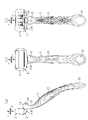
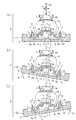
- FIG. 1 is a side view which shows the whole swing-type razor which cap-covered the razor head attached to the holder
- (b) is a front view of the swing-type razor of FIG. 1 (a)
- (c) Is a rear view of the swing razor of FIG. 1 (a).
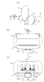
- (A) is a partial enlarged side view of FIG. 1 (a)
- (b) is a partial enlarged front view of FIG. 1 (b)
- (c) is a partial enlarged rear view of FIG. 1 (c)
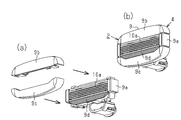
- (A) is a partial enlarged side view showing the razor head with the cap removed.
- (B) is a partial enlarged front view showing the razor head with the cap removed.
- (C) is the cap removed.
- FIG. 5 is a partially enlarged rear view showing the razor head in a state.
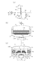
- A is a partially enlarged side sectional view showing the razor head and the head of the holder
- (b) is a partially enlarged rear view showing the razor head removed from the head of the holder
- FIG. 10 is a partially enlarged plan view showing the razor head removed from the head.
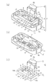
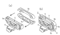
- A) is a rear perspective view showing a state in which the blade assembly, the elastic support and the connection portion are assembled to each other in the razor head removed from the head of the holder
- (b) is a blade assembly before assembly It is a back perspective view showing an attachment
- (c) is a back perspective view showing an elastic support body and a connection part before attachment.
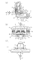
- (A) is a front perspective view showing a blade assembly in which the upper and lower parts are separated from the middle part having a blade, and (b) is a blade assembly in which the upper and lower parts are assembled to the middle part having a blade. It is a front perspective view showing.
- (A) is a rear perspective view showing a blade assembly in which the upper portion and the lower portion are separated from the middle portion having the blade, and (b) is a blade assembly having the upper portion and the lower portion assembled to the middle portion having the blade. It is a rear perspective view showing.
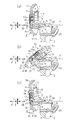
- FIG. (A) is the partial expanded sectional view which looked at the razor head which the blade assembly body is in the neutral position from the side, and (b) and (c) are the partial enlargement sides of the razor head in which the blade assembly is in the movement position.
- FIG. (A) is a partial enlarged plan sectional view showing the razor head in which the blade assembly is in the neutral position, and (b) and (c) are partial enlarged plan sections showing the razor head in which the blade assembly is in the moving position
- the swing razor shown in FIGS. 1 (a) to 1 (c) includes a holder 1, a razor head 2 and a cap 3.
- the razor head 2 comprises a blade assembly 4, an elastic support 5 and a connection 6.
- the elastic support 5 includes a support 7 and a flexible portion 8.
- the blade assembly 4 of the razor head 2 has an intermediate portion 9a, It comprises a frame portion 9 constituted by an upper portion 9 b and a lower portion 9 c.
- the upper part 9b and the lower part 9c are non-removably attached to the middle part 9a.
- a plurality of blade bodies 10 each having a cutting edge 10a are assembled to the intermediate portion 9a.
- the plurality of blades 10 are arranged in the vertical direction Z.
- the blade edge 10 a of each blade 10 is exposed on the front side of the intermediate portion 9 a and extends in the left-right direction Y. As shown in FIG.
- an uneven mounting table 11 is provided on the back side of the intermediate portion 9 a.
- a plate-like regulating unit 12 is provided below the mounting table 11.
- the restricting portion 12 is located at the central portion in the left-right direction Y of the blade assembly 4.
- the restricting portion 12 protrudes in the rearward direction XB from the rear surface of the middle portion 9a.
- a fulcrum groove portion 13 (fulcrum portion) extending in the left-right direction Y is provided between the restricting portion 12 and the mounting table portion 11.
- Shaving aids are attached to the surfaces of the upper 9 b and lower 9 c of the frame 9.
- a soft resin fin 9d is provided on the surface of the lower portion 9c so as to be able to cause wrinkles.
- the support portion 7 of the elastic support 5 of the razor head 2 is formed in a substantially U shape by the upper portion 14a, the left portion 14b (support portion), and the right portion 14c (support portion).
- the mounting unit 14 is provided.
- the connection portion 6 of the razor head 2 is disposed between the left portion 14b and the right portion 14c.
- flexible portions 8 having a rectangular plate shape in cross section are disposed.
- Each of the left portion 14 b and the right portion 14 c is provided with a continuous portion 15 (support portion) integrally formed with the flexible portion 8.
- the mounting portion 14 of the support portion 7 is non-removably attached to the mounting base portion 11 of the blade assembly 4.
- each of the left and right flexible parts 8 has an inner end 8a adjacent to the connection 6 and an outer end 8b opposite to the inner end 8a.
- the outer end 8 b of the left flexible portion 8 is adjacent to the left portion 14 b of the support 7.
- the outer end 8 b of the right flexible portion 8 is adjacent to the right portion 14 c of the support 7.
- the space between the outer ends 8b of the left and right flexible parts 8 constitutes an assumed air space S. More specifically, the assumed air space S is a space on the assumed line L connecting the outer ends 8 b of the left and right flexible portions 8 or a cylindrical air space surrounding the outer periphery of the assumed line L.
- the assumed air space S is a cylindrical air space including an extended line of the outer peripheral edge of the outer end portion 8 b having a predetermined cross-sectional shape such as a rectangular shape.
- Each flexible portion 8 has an inclined portion 16 inclined so as to approach the assumed air space S as it goes from the inner end 8 a to the outer end 8 b of the flexible portion 8.
- the distance between the inclined portions 16 of the left and right flexible portions 8 gradually increases from the inner end 8a toward the outer end 8b.
- the inclined portion 16 is inclined with respect to the assumed air space S when viewed in the front-rear direction X and the up-down direction Z.
- connection portion 6 of the razor head 2 includes a main portion 18, a plate-like tongue piece 19 (projecting piece), and a connecting cylindrical portion 20 (connected Section) and
- the main portion 18 has a continuous portion 17 integrally formed with the left and right flexible portions 8.
- the main body portion 18 is located above the restricting portion 12 of the blade assembly 4 and faces the restricting portion 12.
- the tongue piece 19 extends from the main body 18 in the forward direction XF. That is, the tongue piece 19 (projecting piece) is located on the back side of the blade assembly 4 and protrudes toward the blade assembly 4.
- the connecting cylindrical portion 20 extends from the main portion 18 in the rearward direction XB.
- the dimension of the tongue piece 19 in the left-right direction Y along the extending direction of the blade edge 10 a of the blade 10 corresponds to the width dimension of the tongue piece 19.
- the dimension of the tongue piece 19 in the front-rear direction X orthogonal to the left-right direction Y corresponds to the length dimension of the tongue piece 19.
- the dimension of the tongue piece 19 in the vertical direction Z orthogonal to both the left-right direction Y and the front-rear direction X corresponds to the thickness dimension of the tongue piece 19.
- the thickness dimension of the tongue portion 19 is set smaller than the width dimension and the length dimension of the tongue portion 19.
- the width dimension of the tongue portion 19 is set smaller than the length dimension of the tongue portion 19.
- the free end of the tongue piece 19 is provided with a fulcrum edge 21 (fulcrum) that extends in the left-right direction Y and abuts on the fulcrum groove 13 of the blade assembly 4.
- the dimension between the upper surface and the lower surface of the fulcrum edge 21 corresponds to the thickness dimension of the fulcrum edge 21.
- the upper surface of the fulcrum edge 21 is inclined so that the thickness dimension of the fulcrum edge 21 becomes smaller toward the free end.
- the fulcrum groove 13 of the blade assembly 4 and the fulcrum edge 21 of the tongue piece 19 are disposed below the cutting edge 10 a of the blade 10 and inside the assumed air space S.
- the blade assembly 4 is supported by the support portion 7 of the elastic support 5 as the fulcrum edge 21 and the fulcrum groove 13 abut each other.
- the extending direction of the blade edge 10 a of the blade 10 coincides with the left-right direction Y.
- the longitudinal direction X is orthogonal to the lateral direction Y.
- the up-down direction Z is orthogonal to both the left-right direction Y and the front-rear direction X.
- the blade assembly 4 has a neutral position on the vertical plane V defined by the longitudinal direction X and the vertical direction Z along with the deformation of the flexible portion 8. It can move so as to draw an arc-like locus from P to the longitudinal direction X.
- the blade assembly 4 moves in the moving direction XV along the arc so as to draw an arc-like locus on the vertical plane V. It can move. Then, as shown in FIGS. 8A to 8C, the blade assembly 4 can be disposed at the movement position Q by moving in the movement direction XV along with the deformation of the flexible portion 8. Further, as shown in FIGS. 9A to 9C, the blade assembly 4 is neutral on the horizontal plane H defined by the left and right direction Y and the front and back direction X along with the deformation of the flexible portion 8. It can move so as to draw an arc-like locus from the position P to the longitudinal direction X.
- the blade assembly 4 moves in the moving direction XH along the arc so as to draw an arc-like locus on the horizontal surface H It can. Then, as shown in FIGS. 9A to 9C, the blade assembly 4 can be disposed at the movement position Q by moving in the movement direction XH along with the deformation of the flexible portion 8.
- the fulcrum groove 13 of the blade assembly 4 and the fulcrum edge 21 of the tongue piece 19 are formed in an arc shape along the moving direction XV.
- the supporting point edge 21 of the tongue piece 19 is formed in an arc shape along the moving direction XH.
- the support portion 7 of the elastic support 5 and the connection portion 6 are simultaneously molded in one mold except for the continuous portions 15 and 17. Thereafter, the flexible portion 8 is formed together with the continuous portions 15 and 17, and the support portion 7 and the connection portion 6 are integrally formed by connecting the continuous portions 15 and 17 to each other.
- the holder 1 has a main body 22 which is long in the vertical direction Z, a grip 23 provided on the outer periphery of the main body 22, and an upper end of the main body 22. And a head 24 provided on the The head 24 is provided with a connecting hole 25 (connecting portion) that penetrates the head 24 in the front-rear direction X.
- An elastic engagement / disengagement portion 26 extending in the rearward direction XB is provided in the connection cylindrical portion 20 of the connection portion 6 (see FIG. 4C).
- the connecting cylindrical portion 20 is detachably inserted into the connecting hole portion 25 via the engagement by the elastic engagement / disengagement portion 26. In the inserted state, the head 24 and the connecting portion 6 are integrally continuous with each other.
- the connection cylindrical portion 20 is pulled out of the connection hole 25 by releasing the engagement by the elastic engagement / disengagement portion 26, the head 24 and the connection portion 6 are separated from each other.
- the cap 3 is removably put on the blade assembly 4 of the razor head 2 from the upper side in the vertical direction Z.
- the cap 3 has a back plate 27 facing the back side of the blade assembly 4.
- a stopper stepped portion 28 (stopper portion) is formed on the main body portion 18 of the connection portion 6 of the razor head 2.
- a stopper edge 29 is formed at the lower end of the back plate 27. The stopper edge 29 of the cap 3 is engaged with the stopper step 28 of the razor head 2.
- the cap may be configured to be detachably put on the blade assembly 4 of the razor head 2 from the lower side in the vertical direction Z.
- the main part of the blade assembly 4, the mounting portion 14 of the support portion 7 of the elastic support 5, the connection portion 6, the main portion 22 of the holder 1, and the cap 3 are made of ABS resin or polypropylene resin Etc. It is shape
- the continuous portion 15 of the support portion 7 of the elastic support 5, the flexible portion 8 of the elastic support 5, the continuous portion 17 of the connection portion 6, and the grip portion 23 of the holder 1 It is molded by a soft resin such as a styrene-based elastomer resin.
- a soft resin such as a styrene-based elastomer resin.
- an elastomer resin for forming the flexible portion 8 a material having a hardness in the range of Shore A 40 to Shore D 70 is employed.
- a material having a hardness of Shore A 90 is employed.
- FIGS. 8 (a) and 9 (a) at the neutral position P of the swing razor, the fulcrum groove 13 of the blade assembly 4 and the fulcrum edge 21 of the tongue piece 19 are in contact with each other.
- the left and right flexible parts 8 are stationary in the state of being in contact.
- the razor head 2 extends and stands along the vertical direction Z and the lateral direction Y.
- a slight gap G exists between the regulation portion 12 of the blade assembly 4 of the razor head 2 and the main portion 18 and the tongue piece 19 of the connection portion 6 of the razor head 2. It is formed.
- a swing for rotating the blade assembly 4 along the vertical plane V and a rotation of the blade assembly 4 along the horizontal plane H
- a combination of swinging can also be performed.
- the present embodiment has the following effects.
- (1) The blade assembly 4 is supported by the flexible portion 8 in the razor head 2.
- the support structure for rotatably supporting the blade assembly 4 against the biasing force of the flexible portion 8 can be simplified.
- the flexible portion 8 is provided on the back side of the blade assembly 4. Therefore, since the flexible portion 8 can be easily disposed at a position relatively close to the blade 10, the blade assembly 4 can be operated smoothly on the skin surface in use to improve the feel on the skin surface.
- the blade assembly 4 When rotating the blade assembly 4 against the biasing force of the flexible portion 8 when using the swing razor, the blade assembly 4 is a fulcrum (supporting groove 13, support edge 21) , So that the movement of the blade assembly 4 can be stabilized.
- connection portion 6 and the blade assembly 4 of the razor head 2 can support the blade assembly 4 movably with respect to the connection portion 6 (fulcrum edge 21, fulcrum groove 13) have.
- the support portions 7 of the blade assembly 4 and the elastic support 5 may be supported by the left and right flexible portions 8 by omitting their supporting points.
- you may provide several fulcrum parts other than one fulcrum part.
- the fulcrum (fulcrum edge 21 and fulcrum groove 13) is disposed inside the assumed air space S, but the fulcrum may be disposed outside the assumed air space S.
- the fulcrum edge 21 of the connecting portion 6 and the fulcrum groove 13 of the blade assembly 4 abut each other at the neutral position P and the movement position Q, respectively. That is, at both the neutral position P and the movement position Q, the blade assembly 4 is supported by the connecting portion 6 by the abutment of the fulcrum edge 21 and the fulcrum groove 13.
- the fulcrum edge 21 of the connection portion 6 and the fulcrum groove 13 of the blade assembly 4 may be in contact with each other at at least one of the neutral position P and the movement position Q. That is, at least one of the neutral position P and the movement position Q, the blade assembly 4 may be supported by the connection portion 6 by the abutment of the fulcrum edge 21 and the fulcrum groove 13.
- the fulcrum portions (fulcrum edge 21 and fulcrum groove 13) may be separated at the neutral position P, and when moving from the neutral position P to the movement position Q, the fulcrum portions may abut.
- a swing that rotates the blade assembly 4 along the vertical plane V a swing that rotates the blade assembly 4 along the horizontal surface H, and a swing that combines them. And may be able to perform only one swing.
- the plate-like tongue piece 19 may be configured to be deformable in the thickness direction (vertical direction Z). -Although the plate-like tongue piece 19 is employ
- connection part 6 of the razor head 2 and the head 24 of the holder 1 can be attached or detached via those connection parts (the connection cylinder part 20, the connection hole part 25).
- the razor head 2 may be provided integrally with the holder 1 by omitting the connecting portions.
- other connection structures may be adopted.
- the plate-shaped flexible part 8 of a cross-sectional rectangle was employ
- the flexible portion 8 having the inclined portion 16 is disposed so as to extend mainly in the left-right direction Y.
- the flexible portion 8 may be disposed so as to extend mainly in the vertical direction Z.
- the flexible portions 8 are disposed between the support 7 and the connection 6 on both sides in the left-right direction Y.
- one or three or more flexible portions 8 may be connected to the support 7 and the connection 6 It may be placed between -In the said embodiment, the flexible part 8, the continuous part 15 of the support part 7, and the continuous part 17 of the connection part 6 were shape
- the flexible portion 8, the continuous portion 15, and the continuous portion 17 may be formed in a thin plate shape without using a soft resin, or may be configured to be deformable by forming a thin hinge portion.
- the blade edge 10a of the blade 10 of the razor head 2 extends in the left-right direction Y
- the holder 1 extends in the up-down direction Z, but extends in directions other than the up-down direction Z
- the holder 1 may be arranged in the same manner.
- the shaving aid is attached to the surface of the upper portion 9b and the lower portion 9c of the frame portion 9.
- any one or the middle portion 9a, the upper portion 9b and the lower portion 9c of the frame portion 9 is used. Two or three shaving aids can be attached.
- the shaving aid attached to the surface of the upper portion 9b of the frame 9 and the shaving aid attached to the surface of the lower portion 9c of the frame 9 may have the same components as each other.
- the shaving aid attached to the surface of the upper portion 9b of the frame 9 and the shaving aid attached to the surface of the lower portion 9c of the frame 9 may have different components.
- a shaving aid with moisturizing ingredients may be provided on the surface of the upper part 9b.
- the upper part 9b and the lower part 9c to which the shaving aid is attached are irremovably attached to the middle part 9a, the upper part 9b and the lower part 9c can be replaced so that the upper part 9b and the lower part 9c can be replaced. You may attach to the intermediate part 9a so that attachment or detachment is possible.
Landscapes
- Life Sciences & Earth Sciences (AREA)
- Forests & Forestry (AREA)
- Engineering & Computer Science (AREA)
- Mechanical Engineering (AREA)
- Dry Shavers And Clippers (AREA)
Abstract
Selon l'invention, un rasoir oscillant comprend un support (1) ayant une partie tête (24), et une tête de rasoir (2) fixée au support (1). La tête de rasoir (2) comprend un ensemble lame (4), un corps de support élastique (5), et une partie de liaison (6) reliée à la partie tête (24) du support (1). Le corps de support élastique (5) comprend une partie de support (7) permettant de supporter l'ensemble lame (4) et une partie souple (8) positionnée entre la partie support (7) et la partie de liaison (6). La position à laquelle l'ensemble lame (4) est sollicité par la partie souple (8) du corps de support élastique (5) de façon à être stationnaire est une position neutre (P). L'ensemble lame (4) est capable de se déplacer vers au moins une position de mouvement (Q) qui est déplacée à partir de la position neutre (P) contre la force de poussée de la partie souple (8).
Priority Applications (3)
| Application Number | Priority Date | Filing Date | Title |
|---|---|---|---|
| EP18837518.2A EP3659761B1 (fr) | 2017-07-24 | 2018-07-24 | Rasoir oscillant |
| CN201880048770.XA CN110944812B (zh) | 2017-07-24 | 2018-07-24 | 摇头式剃刀 |
| US16/632,612 US11247358B2 (en) | 2017-07-24 | 2018-07-24 | Pivotal neck razor |
Applications Claiming Priority (2)
| Application Number | Priority Date | Filing Date | Title |
|---|---|---|---|
| JP2017142761A JP6755836B2 (ja) | 2017-07-24 | 2017-07-24 | 首振り式剃刀 |
| JP2017-142761 | 2017-07-24 |
Publications (1)
| Publication Number | Publication Date |
|---|---|
| WO2019022043A1 true WO2019022043A1 (fr) | 2019-01-31 |
Family
ID=65040672
Family Applications (1)
| Application Number | Title | Priority Date | Filing Date |
|---|---|---|---|
| PCT/JP2018/027611 WO2019022043A1 (fr) | 2017-07-24 | 2018-07-24 | Rasoir oscillant |
Country Status (5)
| Country | Link |
|---|---|
| US (1) | US11247358B2 (fr) |
| EP (1) | EP3659761B1 (fr) |
| JP (1) | JP6755836B2 (fr) |
| CN (1) | CN110944812B (fr) |
| WO (1) | WO2019022043A1 (fr) |
Cited By (1)
| Publication number | Priority date | Publication date | Assignee | Title |
|---|---|---|---|---|
| US20210245380A1 (en) * | 2018-07-18 | 2021-08-12 | Bic Violex S.A. | Shaving blade assemblies |
Families Citing this family (2)
| Publication number | Priority date | Publication date | Assignee | Title |
|---|---|---|---|---|
| KR102231870B1 (ko) * | 2019-07-08 | 2021-03-25 | 주식회사 도루코 | 카트리지 커넥터 및 이를 이용한 면도기 조립체 |
| JP2022043782A (ja) * | 2020-09-04 | 2022-03-16 | 株式会社貝印刃物開発センター | ハンドル屈曲剃刀 |
Citations (5)
| Publication number | Priority date | Publication date | Assignee | Title |
|---|---|---|---|---|
| JPH0422388A (ja) | 1990-05-18 | 1992-01-27 | Kaijirushi Hamono Kaihatsu Center:Kk | 安全かみそり |
| JP2000300870A (ja) * | 1999-04-21 | 2000-10-31 | Warner Lambert Co | カミソリカートリッジ |
| JP2001510720A (ja) * | 1997-07-22 | 2001-08-07 | ザ ジレット カンパニー | 安全かみそり |
| US20030213130A1 (en) * | 2002-05-16 | 2003-11-20 | Motta Vincent C. | Razor cartridge mounting structure |
| WO2014073500A1 (fr) * | 2012-11-06 | 2014-05-15 | 株式会社 貝印刃物開発センター | Rasoir |
Family Cites Families (26)
| Publication number | Priority date | Publication date | Assignee | Title |
|---|---|---|---|---|
| US1455751A (en) * | 1922-07-06 | 1923-05-15 | Hartman Harry Buxton | Safety razor |
| US4152828A (en) * | 1978-03-29 | 1979-05-08 | Lund Lloyd W | Razor having variable angle and tilt of its blade |
| DE8903182U1 (fr) * | 1989-03-15 | 1989-05-03 | Wilkinson Sword Gmbh, 5650 Solingen, De | |
| AR244587A1 (es) | 1989-11-17 | 1993-11-30 | Warner Lambert Co | Conjunto afeitador de seguridad movible angularmente |
| US5050301A (en) * | 1990-09-19 | 1991-09-24 | The Gillette Company | Razor assembly |
| ES2299951T3 (es) | 1991-11-27 | 2008-06-01 | The Gillette Company | Maquinillas de afeitar. |
| GB9208098D0 (en) * | 1992-04-13 | 1992-05-27 | Gillette Co | Razor with movable cartridge |
| GB9600818D0 (en) | 1996-01-16 | 1996-03-20 | Gillette Co | Safety razors |
| US5953825A (en) | 1996-01-16 | 1999-09-21 | The Gillette Company | Safety razors |
| US5956851A (en) | 1996-04-10 | 1999-09-28 | The Gillette Company | Shaving system including handle and replaceable cartridges |
| US6085426A (en) | 1996-04-10 | 2000-07-11 | The Gillette Company | Dispensing razor blade cartridges used with a handle |
| US5784790A (en) | 1996-04-10 | 1998-07-28 | The Gillette Company | Shaving razor and method |
| US5787586A (en) | 1996-04-10 | 1998-08-04 | The Gillette Company | Shaving system and method |
| US6041926A (en) | 1996-04-10 | 2000-03-28 | The Gillette Company | Dispensing razor blade cartridges used with a handle |
| US6854188B1 (en) * | 2002-10-24 | 2005-02-15 | American Safety Razor Company | One-piece spring for razor handle |
| US20040177519A1 (en) * | 2003-03-14 | 2004-09-16 | Louis D. Tomassetti | Flexible razor and dispenser with pivoting head |
| DE602004028613D1 (de) * | 2003-06-25 | 2010-09-23 | Eveready Battery Inc | Rasierer mit einem rasierkopf mit mehreren positionen |
| JP3972903B2 (ja) * | 2003-12-26 | 2007-09-05 | 松下電工株式会社 | 電気かみそり |
| US8205344B2 (en) | 2008-08-20 | 2012-06-26 | The Gillette Company | Safety razor having pivotable blade unit |
| JP5513910B2 (ja) * | 2010-01-28 | 2014-06-04 | 株式会社貝印刃物開発センター | 首振り式剃刀 |
| US8745882B2 (en) | 2010-09-29 | 2014-06-10 | The Gillette Company | Flexible and separable portion of a razor handle |
| JP5860707B2 (ja) | 2011-05-18 | 2016-02-16 | 株式会社貝印刃物開発センター | 首振り式剃刀 |
| US9486930B2 (en) | 2012-09-27 | 2016-11-08 | Shavelogic, Inc. | Shaving systems |
| JP6172450B2 (ja) * | 2013-06-04 | 2017-08-02 | 株式会社泉精器製作所 | ロータリー式電気かみそり |
| US9616584B2 (en) * | 2014-03-20 | 2017-04-11 | Rolling Razor, Inc. | Shaving razor and shaving handle with an interconnection mechanism |
| US20170173806A1 (en) * | 2015-12-16 | 2017-06-22 | Tsung-Shih Lee | Biaxial razor |
-
2017
- 2017-07-24 JP JP2017142761A patent/JP6755836B2/ja active Active
-
2018
- 2018-07-24 WO PCT/JP2018/027611 patent/WO2019022043A1/fr unknown
- 2018-07-24 EP EP18837518.2A patent/EP3659761B1/fr active Active
- 2018-07-24 US US16/632,612 patent/US11247358B2/en active Active
- 2018-07-24 CN CN201880048770.XA patent/CN110944812B/zh active Active
Patent Citations (5)
| Publication number | Priority date | Publication date | Assignee | Title |
|---|---|---|---|---|
| JPH0422388A (ja) | 1990-05-18 | 1992-01-27 | Kaijirushi Hamono Kaihatsu Center:Kk | 安全かみそり |
| JP2001510720A (ja) * | 1997-07-22 | 2001-08-07 | ザ ジレット カンパニー | 安全かみそり |
| JP2000300870A (ja) * | 1999-04-21 | 2000-10-31 | Warner Lambert Co | カミソリカートリッジ |
| US20030213130A1 (en) * | 2002-05-16 | 2003-11-20 | Motta Vincent C. | Razor cartridge mounting structure |
| WO2014073500A1 (fr) * | 2012-11-06 | 2014-05-15 | 株式会社 貝印刃物開発センター | Rasoir |
Cited By (2)
| Publication number | Priority date | Publication date | Assignee | Title |
|---|---|---|---|---|
| US20210245380A1 (en) * | 2018-07-18 | 2021-08-12 | Bic Violex S.A. | Shaving blade assemblies |
| US11613033B2 (en) * | 2018-07-18 | 2023-03-28 | BIC Violex Single Member S.A. | Shaving blade assemblies |
Also Published As
| Publication number | Publication date |
|---|---|
| US11247358B2 (en) | 2022-02-15 |
| US20200164536A1 (en) | 2020-05-28 |
| EP3659761B1 (fr) | 2023-09-06 |
| JP6755836B2 (ja) | 2020-09-16 |
| EP3659761A1 (fr) | 2020-06-03 |
| JP2019022601A (ja) | 2019-02-14 |
| CN110944812A (zh) | 2020-03-31 |
| EP3659761A4 (fr) | 2021-04-28 |
| CN110944812B (zh) | 2021-11-30 |
Similar Documents
| Publication | Publication Date | Title |
|---|---|---|
| JP4921747B2 (ja) | 剃刀 | |
| JP4443574B2 (ja) | レザーアッセンブリ | |
| JP5010896B2 (ja) | 剃刀 | |
| WO2019022043A1 (fr) | Rasoir oscillant | |
| JP4975042B2 (ja) | シェービングカートリッジの回動軸 | |
| JP2009539473A (ja) | レーザ・ハンドル | |
| JP5297189B2 (ja) | 分離されるガードバーを有するかみそりカートリッジ | |
| JP3727347B2 (ja) | 二軸旋回シェービング装置 | |
| JP3284474B2 (ja) | 湿式かみそり装置のかみそり装置頭部 | |
| WO2012157624A1 (fr) | Rasoir pivotant | |
| WO2014073501A1 (fr) | Rasoir | |
| JP2007068922A (ja) | 首振り式剃刀 | |
| JPH10258190A (ja) | カミソリヘッド | |
| JP5438816B2 (ja) | シェービング器具 | |
| JP2007089698A (ja) | 電気かみそり | |
| US9889570B2 (en) | Razor with attached shaving aid | |
| JP5243057B2 (ja) | 顔のほか足や腕の毛を剃るための安全かみそり | |
| JP2019022601A5 (fr) | ||
| JP5433320B2 (ja) | T型安全かみそり | |
| JP2003327032A (ja) | ヘッドレスト装置 | |
| JPH07155232A (ja) | 背もたれ付き椅子 | |
| JPH0234193A (ja) | 安全かみそり | |
| JP2001079281A (ja) | 安全かみそり | |
| JP6430742B2 (ja) | シェービングエイド付き剃刀 | |
| JP2017213114A (ja) | 電気かみそり |
Legal Events
| Date | Code | Title | Description |
|---|---|---|---|
| 121 | Ep: the epo has been informed by wipo that ep was designated in this application |
Ref document number: 18837518 Country of ref document: EP Kind code of ref document: A1 |
|
| NENP | Non-entry into the national phase |
Ref country code: DE |
|
| ENP | Entry into the national phase |
Ref document number: 2018837518 Country of ref document: EP Effective date: 20200224 |