EP3659761B1 - Oscillating razor - Google Patents
Oscillating razor Download PDFInfo
- Publication number
- EP3659761B1 EP3659761B1 EP18837518.2A EP18837518A EP3659761B1 EP 3659761 B1 EP3659761 B1 EP 3659761B1 EP 18837518 A EP18837518 A EP 18837518A EP 3659761 B1 EP3659761 B1 EP 3659761B1
- Authority
- EP
- European Patent Office
- Prior art keywords
- blade assembly
- connection unit
- flexible
- portions
- movement
- Prior art date
- Legal status (The legal status is an assumption and is not a legal conclusion. Google has not performed a legal analysis and makes no representation as to the accuracy of the status listed.)
- Active
Links
- 230000007935 neutral effect Effects 0.000 claims description 39
- 230000008878 coupling Effects 0.000 claims description 21
- 238000010168 coupling process Methods 0.000 claims description 21
- 238000005859 coupling reaction Methods 0.000 claims description 21
- 239000004033 plastic Substances 0.000 description 5
- 229920001971 elastomer Polymers 0.000 description 4
- 239000000806 elastomer Substances 0.000 description 4
- PPBRXRYQALVLMV-UHFFFAOYSA-N Styrene Chemical compound C=CC1=CC=CC=C1 PPBRXRYQALVLMV-UHFFFAOYSA-N 0.000 description 2
- 239000011796 hollow space material Substances 0.000 description 2
- 239000000463 material Substances 0.000 description 2
- 238000000465 moulding Methods 0.000 description 2
- 239000004743 Polypropylene Substances 0.000 description 1
- 230000003247 decreasing effect Effects 0.000 description 1
- 230000000694 effects Effects 0.000 description 1
- 238000012986 modification Methods 0.000 description 1
- 230000004048 modification Effects 0.000 description 1
- 230000003020 moisturizing effect Effects 0.000 description 1
- 229920000728 polyester Polymers 0.000 description 1
- -1 polypropylene Polymers 0.000 description 1
- 229920001155 polypropylene Polymers 0.000 description 1
Images


Classifications
-
- B—PERFORMING OPERATIONS; TRANSPORTING
- B26—HAND CUTTING TOOLS; CUTTING; SEVERING
- B26B—HAND-HELD CUTTING TOOLS NOT OTHERWISE PROVIDED FOR
- B26B21/00—Razors of the open or knife type; Safety razors or other shaving implements of the planing type; Hair-trimming devices involving a razor-blade; Equipment therefor
- B26B21/40—Details or accessories
- B26B21/52—Handles, e.g. tiltable, flexible
- B26B21/521—Connection details, e.g. connection to razor heads
-
- B—PERFORMING OPERATIONS; TRANSPORTING
- B26—HAND CUTTING TOOLS; CUTTING; SEVERING
- B26B—HAND-HELD CUTTING TOOLS NOT OTHERWISE PROVIDED FOR
- B26B21/00—Razors of the open or knife type; Safety razors or other shaving implements of the planing type; Hair-trimming devices involving a razor-blade; Equipment therefor
- B26B21/08—Razors of the open or knife type; Safety razors or other shaving implements of the planing type; Hair-trimming devices involving a razor-blade; Equipment therefor involving changeable blades
- B26B21/14—Safety razors with one or more blades arranged transversely to the handle
- B26B21/22—Safety razors with one or more blades arranged transversely to the handle involving several blades to be used simultaneously
- B26B21/222—Safety razors with one or more blades arranged transversely to the handle involving several blades to be used simultaneously with the blades moulded into, or attached to, a changeable unit
- B26B21/225—Safety razors with one or more blades arranged transversely to the handle involving several blades to be used simultaneously with the blades moulded into, or attached to, a changeable unit the changeable unit being resiliently mounted on the handle
-
- B—PERFORMING OPERATIONS; TRANSPORTING
- B26—HAND CUTTING TOOLS; CUTTING; SEVERING
- B26B—HAND-HELD CUTTING TOOLS NOT OTHERWISE PROVIDED FOR
- B26B21/00—Razors of the open or knife type; Safety razors or other shaving implements of the planing type; Hair-trimming devices involving a razor-blade; Equipment therefor
- B26B21/40—Details or accessories
- B26B21/52—Handles, e.g. tiltable, flexible
Definitions
- the present invention relates to a pivotal neck type razor allowing a razor head including a blade body to move relative to a top end of a holder against an elastic force.
- Patent Document 1 describes a known safety razor.
- the safety razor of Patent Document 1 includes a handle, a replaceable blade unit accommodating blade bodies, and a joint located between the handle and the replaceable blade unit.
- the handle includes a pivot shaft that pivotally supports the joint and an elastic member that urges the joint toward a neutral position of the joint.
- the joint includes two journal shafts that support the replaceable blade unit.
- the replaceable blade unit includes two journal bearings arranged in correspondence with the two journal shafts of the joint and an elastic piece that urges the replaceable blade unit toward a neutral position of the replaceable blade unit.
- the two journal shafts of the joint are received by the two journal bearings of the replaceable blade unit so that the joint pivotally supports the replaceable blade unit about the two journal shafts.
- the replaceable blade unit is pivoted about the two journal shafts against an elastic force of the elastic piece from the neutral position of the replaceable blade unit, which is set as the reference. Further, the joint that supports the replaceable blade unit is pivoted together with the replaceable blade unit about the pivot shaft against an elastic force of the elastic member from the neutral position of the joint, which is set as the reference.
- Patent Document 1 Japanese Laid-Open Patent Publication No. 4-22388 ;
- EP1046472A1 discloses a razor assembly that includes a cartridge, a handle assembly, and a pivot frame;
- EP2918383A1 discloses a razor including a razor head attached to a top portion of a holder.
- the safety razor of Patent Document 1 requires separate pivotal support structures for the pivoting direction about the journal shafts and for the pivoting direction about the pivot shaft. Thus, the structure of the razor is complicated.
- a pivotal neck type razor includes a holder including a top end and a razor head attached to the holder.
- the razor head includes an elastic support body, a connection unit that is continuous with the top end of the holder, and a blade assembly that includes a blade body.
- the blade assembly includes a front side from which a blade edge of the blade body is exposed and a rear side that is opposite to the front side.
- the elastic support body is located at the rear side.
- the elastic support body includes a support portion that supports the blade assembly and a flexible portion located between the support portion and the connection unit.
- the blade assembly is urged by the flexible portion of the elastic support body to be stationary at a neutral position.
- the blade assembly is movable to at least one movement position from the neutral position against an urging force of the flexible portion.
- the blade assembly of the razor head attached to the holder is supported by the flexible portion.
- the flexible portion is arranged on the rear side of the blade assembly so that the flexible portion can easily be arranged at a location relatively close to the blade body. This allows for smooth movement of the blade assembly on the skin surface and improves the feel on the skin surface when the pivotal neck type razor is used.
- connection unit and the blade assembly includes a fulcrum portion that supports the blade assembly on the connection unit.
- the support portion is one of two support portions that support the blade assembly
- the flexible portion is one of two flexible portions
- one of the two flexible portions is arranged between one of the two support portions and the connection unit
- the other one of the two flexible portions is arranged between the other one of the two support portions and the connection unit.
- the flexible portions are arranged between the support portions and the connection unit in a stable manner.
- the blade edge extends in a direction corresponding to a right-left direction, and the two flexible portions are arranged at two sides of the connection unit in the right-left direction.
- the dimensions of the razor head are decreased in a front-rear direction so that the razor head is reduced in size.
- the blade edge extends in a direction corresponding to a right-left direction, and the fulcrum portion of the connection unit and the fulcrum portion of the blade assembly are arranged downward from the blade edge in an up-down direction that is orthogonal to the right-left direction.
- connection unit may include a projection located at the rear side of the blade assembly, the projection may project toward the blade assembly and include a free end, and the fulcrum portion of the connection unit may be formed on the free end.
- the blade assembly may move in a movement direction along an arc to form an arcuate path between the neutral position and the movement position.
- the fulcrum portion of the connection unit may be arcuate in correspondence with the movement direction.
- each of the flexible portions may include an inner end that is adjacent to the connection unit and an outer end that is adjacent to one of the two support portions that is adjacent to the flexible portion, a space between the two outer ends of the two flexible portions may define a planned space, and the fulcrum portion of the connection unit and the fulcrum portion of the blade assembly may be arranged inside the planned space.
- the fulcrum portions are arranged inside the planned space between the two outer ends of the two flexible portions. This stabilizes the movement of the flexible portions when the blade assembly is moved against an urging force of the flexible portions, thereby allowing for smooth movement of the blade assembly.
- the blade assembly may be movable in a plurality of movement directions, the at least one movement position may be a plurality of movement positions, and the blade assembly may move in at least one of the movement directions between the neutral position and each of the movement positions.
- the blade assembly moves in the movement directions so that the shaving of the pivotal neck type razor is improved.
- the blade assembly is supported by the abutment of the fulcrum portions at the movement positions. This stabilizes the movement of the blade assembly relative to the connection unit at the movement positions.
- the blade edge may extend in a direction corresponding to a right-left direction
- the right-left direction may be orthogonal to a direction that is a front-rear direction
- the right-left direction and the front-rear direction may be both orthogonal to a direction that is an up-down direction
- the front-rear direction and the up-down direction may define a vertical plane
- the right-left direction and the front-rear direction may define a horizontal plane
- the movement positions may include a first movement position and a second movement position
- the blade assembly may move in a movement direction along an arc to form an arcuate path on the vertical plane between the neutral position and the first movement position
- the blade assembly may move in a movement direction along an arc to form an arcuate path on the horizontal plane between the neutral position and the second movement position.
- the blade assembly moves in the movement directions to form an arcuate path on the vertical plane and on the horizontal plane so that the shaving of the pivotal neck type razor is improved.
- each of the flexible portions may include an inner end that is adjacent to the connection unit, an outer end that is adjacent to one of the two support portions that is adjacent to the flexible portion, and an inclined portion located between the inner end and the outer end, a space between the two outer ends of the two flexible portions may define a planned space, and the inclined portion of each of the flexible portions may be inclined to approach the planned space from the inner end of the flexible portion toward the outer end of the flexible portion.
- the inclined portion prolongs the length between the inner end and the outer end of the flexible portion so that the flexible portion is easily bent.
- the distance between the two flexible portions gradually may increase from the inner ends to the outer ends.
- each of the support portions of the elastic support body may include a continuous portion molded integrally with one of the two flexible portions that is adjacent to the support portion, and the connection unit may include a continuous portion molded integrally with the two flexible portions.
- the two flexible portions are easily attached to the two support portions of the elastic support body and the connection unit of the razor head at the continuous portions.
- connection unit of the razor head and the top end of the holder may each include a coupling portion that couples the connection unit to the top end in a removable manner.
- the razor head is attached in a removable manner to the holder at the coupling portion.
- the present invention simplifies a support structure of a pivotal neck type razor that supports a razor head on a top end of a holder so that the razor head moves relative to the top end of the holder from a neutral position against an elastic force.
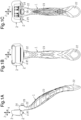
- the pivotal neck type razor shown in Figs. 1A to 1C includes a holder 1, a razor head 2, and a cap 3.
- the razor head 2 includes a blade assembly 4, an elastic support body 5, and a connection unit 6.
- the elastic support body 5 includes a support portion 7 and a flexible portion 8.
- the blade assembly 4 of the razor head 2 includes a frame 9 formed by an intermediate portion 9a, an upper portion 9b, and a lower portion 9c.
- the upper portion 9b and the lower portion 9c are attached to the intermediate portion 9a in a non-removable manner.
- Blade bodies 10, each having a blade edge 10a, are coupled to the intermediate portion 9a.
- the blade bodies 10 are arranged in up-down direction Z.
- the blade edge 10a of each blade body 10 is exposed to the outside at the front side of the intermediate portion 9a and extends in right-left direction Y.
- an uneven mounting base 11 is arranged at the rear side of the intermediate portion 9a inside the frame 9.
- a restriction 12 having the form of a plate is arranged downward from the mounting base 11.
- the restriction 12 is located at a central portion of the blade assembly 4 in right-left direction Y.
- the restriction 12 projects in rearward direction XB from the rear surface of the intermediate portion 9a.
- a fulcrum groove 13 (fulcrum portion) extends in right-left direction Y between the restriction 12 and the mounting base 11.
- Shaving aids are attached to the front surfaces of the upper portion 9b and the lower portion 9c of the frame 9. Further, soft plastic fins 9d are arranged on the front surface of the lower portion 9c to grab a beard.
- the support portion 7 of the elastic support body 5 of the razor head 2 includes a mount 14 formed to be substantially U-shaped by an upper portion 14a, a left portion 14b (support portion), and a right portion 14c (support portion).
- the connection unit 6 of the razor head 2 is arranged between the left portion 14b and the right portion 14c.
- the flexible portion 8, which has the form of a plate with a rectangular cross section, is arranged between the connection unit 6 and the left portion 14b and between the connection unit 6 and the right portion 14c.
- Continuous portions 15 (support portion) that are integrally molded with the flexible portion 8 are arranged on the left portion 14b and the right portion 14c.
- the mount 14 of the support portion 7 is attached in a non-removable manner to the mounting base 11 of the blade assembly 4.
- the right and left flexible portions 8 each include an inner end 8a, which is adjacent to the connection unit 6, and an outer end 8b, which is opposite to the inner end 8a.
- the outer end 8b of the left flexible portion 8 is adjacent to the left portion 14b of the support portion 7.
- the outer end 8b of the right flexible portion 8 is adjacent to the right portion 14c of the support portion 7.
- the space between the two outer ends 8b of the right and left flexible portions 8 defines planned space S.
- planned space S is the space lying along planned line L that connects the outer ends 8b of the right and left flexible portions 8 or a hollow space surrounding planned line L.
- planned space S is a hollow space including lines extended from the outer edges of the outer ends 8b that have a predetermined cross section such as a rectangular cross section.
- the flexible portions 8 each include an inclined portion 16 that is inclined toward planned space S from the inner end 8a to the outer end 8b of the flexible portion 8. The distance between the inclined portions 16 of the right and left flexible portions 8 gradually increases from the inner ends 8a to the outer ends 8b.
- the inclined portions 16 are inclined relative to planned space S in front-rear direction X and up-down direction Z.
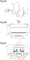
- the connection unit 6 of the razor head 2 includes a main body 18, a flat tongue 19 (projection) and a coupling tube 20 (coupling portion).
- the main body 18 includes a continuous portion 17 integrally molded with the right and left flexible portions 8.
- the main body 18 is arranged upward from the restriction 12 of the blade assembly 4 facing the restriction 12.
- the tongue 19 extends in frontward direction XF from the main body 18. That is, the tongue 19 (projection) is arranged at the rear side of the blade assembly 4 and projects toward the blade assembly 4.
- the coupling tube 20 extends in rearward direction XB from the main body 18.
- the dimension of the tongue 19 in right-left direction Y which is parallel to a direction in which the blade edges 10a of the blade bodies 10 extend, corresponds to the width of the tongue 19.
- the dimension of the tongue 19 in front-rear direction X which is orthogonal to right-left direction Y, corresponds to the length of the tongue 19.
- the dimension of the tongue 19 in up-down direction Z which is orthogonal to right-left direction Y and front-rear direction X, corresponds to the thickness of the tongue 19.
- the thickness of the tongue 19 is less than the width and the length of the tongue 19.
- the width of the tongue 19 is less than the length of the tongue 19.
- a free end of the tongue 19 includes a fulcrum edge 21 (fulcrum portion) extending in right-left direction Y and abutting the fulcrum groove 13 of the blade assembly 4.
- the dimension between the upper surface and the lower surface of the fulcrum edge 21 corresponds to the thickness of the fulcrum edge 21.
- the upper surface of the fulcrum edge 21 is inclined so that the thickness of the fulcrum edge 21 is reduced toward the free end.
- the fulcrum groove 13 of the blade assembly 4 and the fulcrum edge 21 of the tongue 19 are arranged downward from the blade edges 10a of the blade bodies 10 inside planned space S.
- the fulcrum edge 21 and the fulcrum groove 13 are in abutment with each other so that the blade assembly 4 is supported by the support portion 7 of the elastic support body 5.
- the direction in which the blade edges 10a of the blade bodies 10 extend corresponds to right-left direction Y.
- Front-rear direction X is orthogonal to right-left direction Y
- Up-down direction Z is orthogonal to right-left direction Y and front-rear direction X.
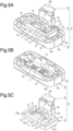
- deformation of the flexible portions 8 allows the blade assembly 4 to move along an arcuate path from neutral position P in front-rear direction X on vertical plane V that is set in front-rear direction X and up-down direction Z.
- movement direction XV when the direction in which the blade assembly 4 is moved is referred to as movement direction XV, the blade assembly 4 may be moved along an arc in movement direction XV so as to form an arcuate path on vertical plane V.
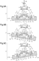
- deformation of the flexible portions 8 allows the blade assembly 4 to move in movement direction XV to movement position Q. Further, as shown in Figs. 9A to 9C , deformation of the flexible portions 8 allows the blade assembly 4 to move along an arcuate path in front-rear direction X from neutral position P on horizontal plane H that is set in right-left direction Y and front-rear direction X. Specifically, when the direction in which the blade assembly 4 is moved is referred to as movement direction XH, the blade assembly 4 may be moved along an arc in movement direction XH so as to form an arcuate path on horizontal plane H. As shown in Figs.
- deformation of the flexible portions 8 allows the blade assembly 4 to move in movement direction XH to movement position Q.
- the fulcrum groove 13 of the blade assembly 4 and the fulcrum edge 21 of the tongue 19 are shaped to be arcuate in correspondence with movement direction XV.
- the fulcrum edge 21 of the tongue 19 is shaped to be arcuate in correspondence with movement direction XH.
- the support portion 7 of the elastic support body 5 and the connection unit 6, excluding the continuous portions 15, 17, are simultaneously molded in the same mold. Then, the flexible portions 8 are molded together with the continuous portions 15, 17 so that the continuous portions 15, 17 integrally connect the support portion 7 and the connection unit 6
- the holder 1 includes a main body 22 elongated in up-down direction Z, a handle 23 arranged on the main body 22, and a top end 24 arranged at the upper end of the main body 22.
- the top end 24 includes a coupling hole 25 (coupling portion) that extends through the top end 24 in front-rear direction X.
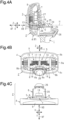
- the coupling tube 20 of the connection unit 6 includes an elastic engagement portion 26 that extends in rearward direction XB (refer to Fig. 4C ).
- the coupling tube 20 is inserted into and attached in a removable manner to the coupling hole 25 through engagement of the elastic engagement portion 26. In the inserted and attached state, the top end 24 and the connection unit 6 are integrally continuous with each other.
- the elastic engagement portion 26 is disengaged and the coupling tube 20 is removed from the coupling hole 25, the top end 24 and the connection unit 6 are separated from each other.
- the cap 3 covers the blade assembly 4 of the razor head 2 in a removable manner from above in up-down direction Z.
- the cap 3 includes a back plate 27 that faces the rear side of the blade assembly 4.
- the main body 18 of the connection unit 6 of the razor head 2 includes a stopper step 28 (stopper).
- the lower end of the back plate 27 defines a stopper edge 29 (stopper).
- the stopper edge 29 of the cap 3 is engaged with the stopper step 28 of the razor head 2.
- the cap may be configured to cover the blade assembly 4 of the razor head 2 in a removable manner from below in up-down direction Z.
- a main part of the blade assembly 4, the mount 14 of the support portion 7 of the elastic support body 5, the connection unit 6, the main body 22 of the holder 1, and the cap 3 are made of a hard plastic such as ABS or polypropylene.
- the continuous portions 15 of the support portion 7 of the elastic support body 5, the flexible portions 8 of the elastic support body 5, the continuous portion 17 of the connection unit 6, and the handle 23 of the holder 1 are made of a soft plastic such as polyester elastomer or styrene elastomer.
- Elastomer for molding the flexible portions 8 may be a material having a hardness range from Shore A40 to Shore D70.
- elastomer for molding the flexible portions 8 may be a material having a hardness of Shore A90.
- the right and left flexible portions 8 are stationary when the fulcrum groove 13 of the blade assembly 4 and the fulcrum edge 21 of the tongue 19 are in abutment with each other.
- the razor head 2 extends in up-down direction Z and right-left direction Y and is stationary.
- slight gap G is formed between the restriction 12 of the blade assembly 4 of the razor head 2 and both of the main body 18 and tongue 19 of the connection unit 6 of the razor head 2.
- pivoting may be performed by combining pivoting of the blade assembly 4 along vertical plane V (refer to Figs. 8B and 8C ) and pivoting of the blade assembly 4 along horizontal plane H (refer to Figs. 9B and 9C ).
- the present embodiment has the following advantages.
- connection unit 6 and the blade assembly 4 of the razor head 2 include the fulcrum portions (fulcrum groove 13, fulcrum edge 21) that movably support the blade assembly 4 relative to the connection unit 6.
- the fulcrum portions may be omitted and the right and left flexible portions 8 may support the blade assembly 4 and the support portion 7 of the elastic support body 5.
- plural fulcrum portions may be arranged.
- the fulcrum portions are arranged inside planned space S.
- the fulcrum portions may be arranged outside planned space S.
- the fulcrum edge 21 of the connection unit 6 and the fulcrum groove 13 of the blade assembly 4 are in abutment with each other at neutral position P and movement position Q.
- the blade assembly 4 is supported by the connection unit 6 by the abutment between the fulcrum edge 21 and fulcrum groove 13 at neutral position P and movement position Q.
- the fulcrum edge 21 of the connection unit 6 and the fulcrum groove 13 of the blade assembly 4 need only to abut each other in at least one of neutral position P and movement position Q.
- the blade assembly 4 need only be supported by the connection unit 6 through abutment of the fulcrum edge 21 and fulcrum groove 13 in at least one of neutral position P and movement position Q.
- the fulcrum portions (fulcrum edge 21, fulcrum groove 13) may be separated at neutral position P and the fulcrum portions may be brought into abutment during movement from neutral position P to movement position Q.
- the embodiment allows for pivoting of the blade assembly 4 along vertical plane V, pivoting of the blade assembly 4 on horizontal plane H, and a combination of these pivotings. However, modifications may be made so that only one of these pivotings is performed.
- the flat tongue 19 may be deformable in the thickness direction (up-down direction Z).
- the flat tongue 19 is used.
- the tongue 19 may be replaced with a rod-shaped projection.
- the projection may include a semispherical fulcrum portion at the distal end.
- connection unit 6 of the razor head 2 is attached in a removable manner to the top end 24 of the holder 1 at the coupling portions (coupling tube 20, coupling hole 25).
- the coupling portions may be omitted and the razor head 2 may be integrated with the holder 1.
- the connection unit 6 and the top end 24 may have a coupling structure reversing the projection-recess relationship that allows for attachment and removal. Further, other coupling structures may be used.
- the flexible portion 8 has the form of a plate with a rectangular cross section.
- the flexible portion may have a circular, triangular, or T-shaped cross section.
- the flexible portions 8 including the inclined portions 16 are arranged to substantially extend in right-left direction Y. Instead, the flexible portions 8 may be arranged to substantially extend in up-down direction Z.
- the flexible portions 8 are arranged between the support portion 7 and the connection unit 6 at two sides in right-left direction Y. Instead, one or more than two flexible portions 8 may be arranged between the support portion 7 and the connection unit 6.
- the flexible portions 8, the continuous portions 15 of the support portion 7, and the continuous portion 17 of the connection unit 6 are made of soft plastic.
- the flexible portions 8, the continuous portion 15, and the continuous portion 17 may be formed as thin plates or thin hinges without using soft plastic so that the portions can be deformed.
- the blade edges 10a of the blade bodies 10 of the razor head 2 extend in right-left direction Y and the holder 1 extends in up-down direction Z.
- the holder 1 may be arranged to extend in a direction other than up-down direction Z.
- the shaving aids are attached to the front surfaces of the upper portion 9b and the lower portion 9c of the frame 9.
- the shaving aid may be applied to any one, two, or three of the intermediate portion 9a, the upper portion 9b, and the lower portion 9c of the frame 9.
- the shaving aid attached to the front surface of the upper portion 9b of the frame 9 may contain the same component as the shaving aid attached to the front surface of the lower portion 9c of the frame 9.
- the shaving aid attached to the front surface of the upper portion 9b of the frame 9 may contain a different component as the shaving aid attached to the front surface of the lower portion 9c of the frame 9.
- a shaving aid containing a moisturizing component may be attached to the front surface of the upper portion 9b.
- the upper portion 9b and the lower portion 9c to which shaving aids are applied are attached to the intermediate portion 9a in a non-removable manner.
- the upper portion 9b and the lower portion 9c may be attached to the intermediate portion 9a in a removable manner so that the upper portion 9b and the lower portion 9c can be replaced.
Applications Claiming Priority (2)
| Application Number | Priority Date | Filing Date | Title |
|---|---|---|---|
| JP2017142761A JP6755836B2 (ja) | 2017-07-24 | 2017-07-24 | 首振り式剃刀 |
| PCT/JP2018/027611 WO2019022043A1 (ja) | 2017-07-24 | 2018-07-24 | 首振り式剃刀 |
Publications (3)
| Publication Number | Publication Date |
|---|---|
| EP3659761A1 EP3659761A1 (en) | 2020-06-03 |
| EP3659761A4 EP3659761A4 (en) | 2021-04-28 |
| EP3659761B1 true EP3659761B1 (en) | 2023-09-06 |
Family
ID=65040672
Family Applications (1)
| Application Number | Title | Priority Date | Filing Date |
|---|---|---|---|
| EP18837518.2A Active EP3659761B1 (en) | 2017-07-24 | 2018-07-24 | Oscillating razor |
Country Status (5)
| Country | Link |
|---|---|
| US (1) | US11247358B2 (ja) |
| EP (1) | EP3659761B1 (ja) |
| JP (1) | JP6755836B2 (ja) |
| CN (1) | CN110944812B (ja) |
| WO (1) | WO2019022043A1 (ja) |
Families Citing this family (3)
| Publication number | Priority date | Publication date | Assignee | Title |
|---|---|---|---|---|
| EP3823800A1 (en) * | 2018-07-18 | 2021-05-26 | Bic Violex S.A. | Shaving blade assemblies |
| KR102231870B1 (ko) * | 2019-07-08 | 2021-03-25 | 주식회사 도루코 | 카트리지 커넥터 및 이를 이용한 면도기 조립체 |
| JP2022043782A (ja) * | 2020-09-04 | 2022-03-16 | 株式会社貝印刃物開発センター | ハンドル屈曲剃刀 |
Family Cites Families (31)
| Publication number | Priority date | Publication date | Assignee | Title |
|---|---|---|---|---|
| US1455751A (en) * | 1922-07-06 | 1923-05-15 | Hartman Harry Buxton | Safety razor |
| US4152828A (en) * | 1978-03-29 | 1979-05-08 | Lund Lloyd W | Razor having variable angle and tilt of its blade |
| DE8903182U1 (ja) * | 1989-03-15 | 1989-05-03 | Wilkinson Sword Gmbh, 5650 Solingen, De | |
| AR244587A1 (es) | 1989-11-17 | 1993-11-30 | Warner Lambert Co | Conjunto afeitador de seguridad movible angularmente |
| JPH0422388A (ja) | 1990-05-18 | 1992-01-27 | Kaijirushi Hamono Kaihatsu Center:Kk | 安全かみそり |
| US5050301A (en) * | 1990-09-19 | 1991-09-24 | The Gillette Company | Razor assembly |
| RO113014B1 (ro) * | 1991-11-27 | 1998-03-30 | Gillette Co | Aparat de ras |
| GB9208098D0 (en) * | 1992-04-13 | 1992-05-27 | Gillette Co | Razor with movable cartridge |
| US5953825A (en) | 1996-01-16 | 1999-09-21 | The Gillette Company | Safety razors |
| GB9600818D0 (en) | 1996-01-16 | 1996-03-20 | Gillette Co | Safety razors |
| US6041926A (en) | 1996-04-10 | 2000-03-28 | The Gillette Company | Dispensing razor blade cartridges used with a handle |
| US5787586A (en) | 1996-04-10 | 1998-08-04 | The Gillette Company | Shaving system and method |
| US5956851A (en) | 1996-04-10 | 1999-09-28 | The Gillette Company | Shaving system including handle and replaceable cartridges |
| US5784790A (en) | 1996-04-10 | 1998-07-28 | The Gillette Company | Shaving razor and method |
| US6085426A (en) | 1996-04-10 | 2000-07-11 | The Gillette Company | Dispensing razor blade cartridges used with a handle |
| GB9715501D0 (en) | 1997-07-22 | 1997-10-01 | Gillette Co | Safety razors |
| US6138361A (en) * | 1999-04-21 | 2000-10-31 | Warner-Lambert Company | Pivotable razor assembly and cartridge |
| AU2003212586A1 (en) | 2002-05-16 | 2003-12-02 | Warner-Lambert Company Llc | Razor cartridge mounting structure |
| US6854188B1 (en) * | 2002-10-24 | 2005-02-15 | American Safety Razor Company | One-piece spring for razor handle |
| US20040177519A1 (en) * | 2003-03-14 | 2004-09-16 | Louis D. Tomassetti | Flexible razor and dispenser with pivoting head |
| EP1635998B1 (en) * | 2003-06-25 | 2010-08-11 | Eveready Battery Company, Inc. | Razor having a multi-position shaving head |
| JP3972903B2 (ja) * | 2003-12-26 | 2007-09-05 | 松下電工株式会社 | 電気かみそり |
| US8205344B2 (en) | 2008-08-20 | 2012-06-26 | The Gillette Company | Safety razor having pivotable blade unit |
| JP5513910B2 (ja) * | 2010-01-28 | 2014-06-04 | 株式会社貝印刃物開発センター | 首振り式剃刀 |
| US8745882B2 (en) | 2010-09-29 | 2014-06-10 | The Gillette Company | Flexible and separable portion of a razor handle |
| JP5860707B2 (ja) | 2011-05-18 | 2016-02-16 | 株式会社貝印刃物開発センター | 首振り式剃刀 |
| US9486930B2 (en) | 2012-09-27 | 2016-11-08 | Shavelogic, Inc. | Shaving systems |
| JP6093551B2 (ja) | 2012-11-06 | 2017-03-08 | 株式会社貝印刃物開発センター | 剃刀 |
| JP6172450B2 (ja) * | 2013-06-04 | 2017-08-02 | 株式会社泉精器製作所 | ロータリー式電気かみそり |
| US9616584B2 (en) | 2014-03-20 | 2017-04-11 | Rolling Razor, Inc. | Shaving razor and shaving handle with an interconnection mechanism |
| US20170173806A1 (en) * | 2015-12-16 | 2017-06-22 | Tsung-Shih Lee | Biaxial razor |
-
2017
- 2017-07-24 JP JP2017142761A patent/JP6755836B2/ja active Active
-
2018
- 2018-07-24 EP EP18837518.2A patent/EP3659761B1/en active Active
- 2018-07-24 US US16/632,612 patent/US11247358B2/en active Active
- 2018-07-24 CN CN201880048770.XA patent/CN110944812B/zh active Active
- 2018-07-24 WO PCT/JP2018/027611 patent/WO2019022043A1/ja unknown
Also Published As
| Publication number | Publication date |
|---|---|
| WO2019022043A1 (ja) | 2019-01-31 |
| CN110944812B (zh) | 2021-11-30 |
| JP6755836B2 (ja) | 2020-09-16 |
| EP3659761A4 (en) | 2021-04-28 |
| CN110944812A (zh) | 2020-03-31 |
| JP2019022601A (ja) | 2019-02-14 |
| US11247358B2 (en) | 2022-02-15 |
| EP3659761A1 (en) | 2020-06-03 |
| US20200164536A1 (en) | 2020-05-28 |
Similar Documents
| Publication | Publication Date | Title |
|---|---|---|
| EP2918383B1 (en) | Razor | |
| EP3659761B1 (en) | Oscillating razor | |
| US9498892B2 (en) | Pivoting razor | |
| US9919440B2 (en) | Razor | |
| US8166658B2 (en) | Razor | |
| JP4939785B2 (ja) | 首振り式剃刀 | |
| JP2005185856A (ja) | シェービングカミソリハンドル | |
| JP2018507734A (ja) | 剃毛かみそりカートリッジ | |
| US10632635B2 (en) | Razor | |
| EP2918382B1 (en) | Razor with attached shaving aid | |
| JPH038226Y2 (ja) | ||
| JP5109158B2 (ja) | カッターナイフ | |
| US20230390953A1 (en) | Razor cartridge | |
| US20220063120A1 (en) | Razor cartridge | |
| KR20230164326A (ko) | 면도기 카트리지 및 탈착 부재 | |
| JPS592785Y2 (ja) | 安全カミソリ |
Legal Events
| Date | Code | Title | Description |
|---|---|---|---|
| STAA | Information on the status of an ep patent application or granted ep patent |
Free format text: STATUS: THE INTERNATIONAL PUBLICATION HAS BEEN MADE |
|
| PUAI | Public reference made under article 153(3) epc to a published international application that has entered the european phase |
Free format text: ORIGINAL CODE: 0009012 |
|
| STAA | Information on the status of an ep patent application or granted ep patent |
Free format text: STATUS: REQUEST FOR EXAMINATION WAS MADE |
|
| 17P | Request for examination filed |
Effective date: 20200204 |
|
| AK | Designated contracting states |
Kind code of ref document: A1 Designated state(s): AL AT BE BG CH CY CZ DE DK EE ES FI FR GB GR HR HU IE IS IT LI LT LU LV MC MK MT NL NO PL PT RO RS SE SI SK SM TR |
|
| AX | Request for extension of the european patent |
Extension state: BA ME |
|
| DAV | Request for validation of the european patent (deleted) | ||
| DAX | Request for extension of the european patent (deleted) | ||
| A4 | Supplementary search report drawn up and despatched |
Effective date: 20210326 |
|
| RIC1 | Information provided on ipc code assigned before grant |
Ipc: B26B 21/52 20060101AFI20210322BHEP Ipc: B26B 21/22 20060101ALI20210322BHEP |
|
| GRAP | Despatch of communication of intention to grant a patent |
Free format text: ORIGINAL CODE: EPIDOSNIGR1 |
|
| RIC1 | Information provided on ipc code assigned before grant |
Ipc: B26B 21/22 20060101ALI20230309BHEP Ipc: B26B 21/52 20060101AFI20230309BHEP |
|
| STAA | Information on the status of an ep patent application or granted ep patent |
Free format text: STATUS: GRANT OF PATENT IS INTENDED |
|
| INTG | Intention to grant announced |
Effective date: 20230413 |
|
| GRAS | Grant fee paid |
Free format text: ORIGINAL CODE: EPIDOSNIGR3 |
|
| GRAA | (expected) grant |
Free format text: ORIGINAL CODE: 0009210 |
|
| STAA | Information on the status of an ep patent application or granted ep patent |
Free format text: STATUS: THE PATENT HAS BEEN GRANTED |
|
| P01 | Opt-out of the competence of the unified patent court (upc) registered |
Effective date: 20230720 |
|
| AK | Designated contracting states |
Kind code of ref document: B1 Designated state(s): AL AT BE BG CH CY CZ DE DK EE ES FI FR GB GR HR HU IE IS IT LI LT LU LV MC MK MT NL NO PL PT RO RS SE SI SK SM TR |
|
| REG | Reference to a national code |
Ref country code: GB Ref legal event code: FG4D |
|
| REG | Reference to a national code |
Ref country code: CH Ref legal event code: EP |
|
| REG | Reference to a national code |
Ref country code: IE Ref legal event code: FG4D |
|
| REG | Reference to a national code |
Ref country code: DE Ref legal event code: R096 Ref document number: 602018057146 Country of ref document: DE |
|
| REG | Reference to a national code |
Ref country code: LT Ref legal event code: MG9D |
|
| REG | Reference to a national code |
Ref country code: NL Ref legal event code: MP Effective date: 20230906 |
|
| PG25 | Lapsed in a contracting state [announced via postgrant information from national office to epo] |
Ref country code: GR Free format text: LAPSE BECAUSE OF FAILURE TO SUBMIT A TRANSLATION OF THE DESCRIPTION OR TO PAY THE FEE WITHIN THE PRESCRIBED TIME-LIMIT Effective date: 20231207 |
|
| PG25 | Lapsed in a contracting state [announced via postgrant information from national office to epo] |
Ref country code: SE Free format text: LAPSE BECAUSE OF FAILURE TO SUBMIT A TRANSLATION OF THE DESCRIPTION OR TO PAY THE FEE WITHIN THE PRESCRIBED TIME-LIMIT Effective date: 20230906 Ref country code: RS Free format text: LAPSE BECAUSE OF FAILURE TO SUBMIT A TRANSLATION OF THE DESCRIPTION OR TO PAY THE FEE WITHIN THE PRESCRIBED TIME-LIMIT Effective date: 20230906 Ref country code: NO Free format text: LAPSE BECAUSE OF FAILURE TO SUBMIT A TRANSLATION OF THE DESCRIPTION OR TO PAY THE FEE WITHIN THE PRESCRIBED TIME-LIMIT Effective date: 20231206 Ref country code: LV Free format text: LAPSE BECAUSE OF FAILURE TO SUBMIT A TRANSLATION OF THE DESCRIPTION OR TO PAY THE FEE WITHIN THE PRESCRIBED TIME-LIMIT Effective date: 20230906 Ref country code: LT Free format text: LAPSE BECAUSE OF FAILURE TO SUBMIT A TRANSLATION OF THE DESCRIPTION OR TO PAY THE FEE WITHIN THE PRESCRIBED TIME-LIMIT Effective date: 20230906 Ref country code: HR Free format text: LAPSE BECAUSE OF FAILURE TO SUBMIT A TRANSLATION OF THE DESCRIPTION OR TO PAY THE FEE WITHIN THE PRESCRIBED TIME-LIMIT Effective date: 20230906 Ref country code: GR Free format text: LAPSE BECAUSE OF FAILURE TO SUBMIT A TRANSLATION OF THE DESCRIPTION OR TO PAY THE FEE WITHIN THE PRESCRIBED TIME-LIMIT Effective date: 20231207 Ref country code: FI Free format text: LAPSE BECAUSE OF FAILURE TO SUBMIT A TRANSLATION OF THE DESCRIPTION OR TO PAY THE FEE WITHIN THE PRESCRIBED TIME-LIMIT Effective date: 20230906 |
|
| REG | Reference to a national code |
Ref country code: AT Ref legal event code: MK05 Ref document number: 1607895 Country of ref document: AT Kind code of ref document: T Effective date: 20230906 |
|
| PG25 | Lapsed in a contracting state [announced via postgrant information from national office to epo] |
Ref country code: NL Free format text: LAPSE BECAUSE OF FAILURE TO SUBMIT A TRANSLATION OF THE DESCRIPTION OR TO PAY THE FEE WITHIN THE PRESCRIBED TIME-LIMIT Effective date: 20230906 |
|
| PG25 | Lapsed in a contracting state [announced via postgrant information from national office to epo] |
Ref country code: IS Free format text: LAPSE BECAUSE OF FAILURE TO SUBMIT A TRANSLATION OF THE DESCRIPTION OR TO PAY THE FEE WITHIN THE PRESCRIBED TIME-LIMIT Effective date: 20240106 |
|
| PG25 | Lapsed in a contracting state [announced via postgrant information from national office to epo] |
Ref country code: AT Free format text: LAPSE BECAUSE OF FAILURE TO SUBMIT A TRANSLATION OF THE DESCRIPTION OR TO PAY THE FEE WITHIN THE PRESCRIBED TIME-LIMIT Effective date: 20230906 |