WO2019021724A1 - タイヤ - Google Patents
タイヤ Download PDFInfo
- Publication number
- WO2019021724A1 WO2019021724A1 PCT/JP2018/024231 JP2018024231W WO2019021724A1 WO 2019021724 A1 WO2019021724 A1 WO 2019021724A1 JP 2018024231 W JP2018024231 W JP 2018024231W WO 2019021724 A1 WO2019021724 A1 WO 2019021724A1
- Authority
- WO
- WIPO (PCT)
- Prior art keywords
- tire
- reinforcing rubber
- rubber layer
- layer
- width direction
- Prior art date
Links
Images


Classifications
-
- B—PERFORMING OPERATIONS; TRANSPORTING
- B60—VEHICLES IN GENERAL
- B60C—VEHICLE TYRES; TYRE INFLATION; TYRE CHANGING; CONNECTING VALVES TO INFLATABLE ELASTIC BODIES IN GENERAL; DEVICES OR ARRANGEMENTS RELATED TO TYRES
- B60C17/00—Tyres characterised by means enabling restricted operation in damaged or deflated condition; Accessories therefor
- B60C17/0009—Tyres characterised by means enabling restricted operation in damaged or deflated condition; Accessories therefor comprising sidewall rubber inserts, e.g. crescent shaped inserts
-
- B—PERFORMING OPERATIONS; TRANSPORTING
- B60—VEHICLES IN GENERAL
- B60C—VEHICLE TYRES; TYRE INFLATION; TYRE CHANGING; CONNECTING VALVES TO INFLATABLE ELASTIC BODIES IN GENERAL; DEVICES OR ARRANGEMENTS RELATED TO TYRES
- B60C17/00—Tyres characterised by means enabling restricted operation in damaged or deflated condition; Accessories therefor
-
- B—PERFORMING OPERATIONS; TRANSPORTING
- B60—VEHICLES IN GENERAL
- B60C—VEHICLE TYRES; TYRE INFLATION; TYRE CHANGING; CONNECTING VALVES TO INFLATABLE ELASTIC BODIES IN GENERAL; DEVICES OR ARRANGEMENTS RELATED TO TYRES
- B60C19/00—Tyre parts or constructions not otherwise provided for
- B60C19/002—Noise damping elements provided in the tyre structure or attached thereto, e.g. in the tyre interior
Definitions
- the present invention relates to a tire.
- the gas filled in the tire lumen causes cavity resonance.
- This cavity resonance is one of the noise caused by the tire, and most of its resonance frequency is in the range of 180 to 300 Hz.
- the cavity resonance sound is transmitted into the vehicle compartment, unlike the noise in the other frequency bands, it has a sharp high peak value, which is annoying to the passenger in the vehicle compartment.
- Patent Document 2 As a way to reduce such cavity resonance noise, for example, there is known a technique of providing a noise suppressing layer made of a sponge or the like on the tire inner cavity side of the inner liner (for example, Patent Document 2).
- the calorific value at the time of load rolling of the tire is increased as compared to a tire not having the reinforcing rubber layer. Therefore, in the side reinforced run flat tire, when the above-described noise suppressing layer is provided to reduce cavity resonance noise, the heat radiation of the tire is reduced, and the durability of the tire, in particular, the heat generation amount in the reinforced rubber layer In particular, there is a risk that the durability of the tire during run flat running may decrease. In addition, in run flat tires, it is also desired to improve the steering stability during run flat running.
- an object of the present invention is to provide a tire in which the durability and the steering stability of the tire during run flat running are improved while the cavity resonance noise is reduced.
- the tire according to the present invention has a pair of bead portions, a pair of sidewall portions disposed on the tire radial direction outer side of the bead portions, and a tread portion disposed between the sidewall portions,
- the tire is provided with a reinforcing rubber layer in a wall portion, and the reinforcing rubber layer extends from the sidewall portion over at least a portion of the tread portion, and at least a portion of the inner circumferential surface of the tire
- a noise suppressing layer is provided, wherein the noise suppressing layer is not laminated on the reinforcing rubber layer.
- the noise control layer is laminated on the reinforcing rubber layer
- the noise control layer is directly fixed to the reinforcing rubber layer, or the noise control layer is another component on the reinforcing rubber layer. It means that it is indirectly fixed via
- "on the reinforcing rubber layer” means on the inner circumferential surface of the tire corresponding to the extension region of the reinforcing rubber layer.
- the “bead portion” refers to a region from the bead toe of the tire to the separation point of the rim to be assembled to the tire. More specifically, it refers to the area extending between the bead toe and the normal to the outer surface of the tire drawn at the point of separation of the rim.
- the “sidewall portion” refers to a region from the separation point of the rim assembled to the tire to the tread contact end. More specifically, it refers to a region extending between the normal to the tire outer surface drawn at the rim separation point and the normal to the tire outer surface drawn at the tread contact edge.
- tread ground contact end refers to a tread tread surface (a tire that is assembled to a rim and filled with a predetermined internal pressure and is brought into contact with the road surface when loaded under a maximum load).
- tread portion refers to a region between tread tread ends. More specifically, it refers to a region extending between the normal of the tire outer surface drawn at one tread ground contact end and the normal of the tire outer surface drawn at the other tread ground contact end.
- rim is an industrial standard effective for the area where tires are produced and used.
- JATMA Joint Automobile Tire Association
- JATMA YEAR BOOK and in Europe ETRTO (The European Tire and Standard rims in application size (STANDARDS MANUAL at ETRTO, Measured at Rim Technical Organization) STANDARDS MANUAL in the US, YEAR BOOK etc.
- TRA The Tire and Rim Association, Inc.
- TRA's YEAR BOOK refers to Design Rim) (ie, the "rim” above includes the current size plus a size that may be included in the above industry standard in the future.
- predetermined internal pressure refers to the air pressure (maximum air pressure) corresponding to the maximum load capacity of a single wheel in application size and ply rating described in the above-mentioned JATMA YEAR BOOK etc.
- predetermined internal pressure refers to the air pressure (maximum air pressure) corresponding to the maximum load capacity defined for each vehicle on which the tire is mounted.
- maximum load load shall mean the load corresponding to the above-mentioned maximum load capacity.
- the “reference state” described later in the present specification refers to a state in which the tire is assembled to the rim, filled with a predetermined internal pressure, and not loaded.
- FIG. 1 is a partial cross-sectional view showing a tire width direction cross-section of a half of a tire 10 according to an embodiment of the present invention.
- the half portion of the tire 10 (not shown) also has the same configuration as the half portion of the tire 10 shown.
- the tire 10 according to the present embodiment includes a pair of bead portions 1, a pair of sidewall portions 2 disposed radially outward of the bead portions 1, and a tread portion 3 disposed between the sidewall portions 2.
- each side wall portion 2 is provided with a reinforcing rubber layer 4 having a crescent-like cross section.
- the tire 10 has a toroidal shape between the bead cores 5 disposed in each of the pair of bead portions 1, the carcass 6 and the toroidal between the bead cores 5 on the inner peripheral side of the tire than the carcass 6. And an inner liner 7 forming an inner circumferential surface of the tire 10, and a reinforcing rubber layer 4 is disposed between the carcass 6 and the inner liner 7.
- the inner liner 7 in the present embodiment extends from the vicinity of the bead toe of one bead portion 1 to the vicinity of the bead toe of the other bead portion 1 and extends substantially over the entire inner circumferential surface of the tire. Therefore, in the sidewall portion 2 of the tire 10, the inner liner 7, the reinforcing rubber layer 4, and the carcass 6 are laminated in this order from the inner peripheral side of the tire 10.
- the reinforcing rubber layer 4 in the present embodiment extends from the vicinity of the tire radial direction inner end edge 2E of the sidewall portion 2 to the tire radial direction outer side over the tire radial direction region of the sidewall portion 2. , Extends over at least a portion of the tread portion 3. That is, the reinforcing rubber layer 4 in the present embodiment is terminated on the inner side in the tire width direction than the outer edge 3E of the tread portion 3 in the tire width direction.
- the reinforcing rubber layer 4 is continuous in the circumferential direction of the tire and extends in an annular shape.
- a noise control layer 8 made of a porous material is provided in at least a part of the inner circumferential surface of the tire (in the present embodiment, a region including the tire equatorial plane CL on the inner circumferential surface of the tread portion 3).
- the noise suppressing layer 8 is disposed such that the tire width direction end 8E of the noise suppressing layer 8 is positioned more inward in the tire width direction than the tire radial direction outer end 4E of the reinforcing rubber layer 4, that is, on the tire equatorial plane CL side. It is done.
- the noise suppressing layer 8 is disposed so as not to be laminated on the reinforcing rubber layer 4.
- the noise control layer 8 covering at least a part of the inner peripheral surface of the tire is provided, it is possible to reduce the cavity resonance noise while the vehicle is traveling. Further, since the sound damping layer 8 is not laminated on the reinforcing rubber layer 4, heat dissipation in the reinforcing rubber layer 4 is not suppressed by the noise damping layer 8, and the heat is not easily stored in the reinforcing rubber layer 4. Therefore, since the temperature rise in the reinforcement rubber layer 4 which becomes remarkable especially in the side reinforcement type run flat tire is suppressed, the durability of the tire at the time of run flat traveling can be improved.
- the noise control layer 8 in the present embodiment is made of a sponge material.
- the sponge material is a sponge-like porous structure, and includes, for example, a so-called sponge having open cells in which rubber or synthetic resin is foamed.
- the sponge material includes web-like materials in which animal fibers, plant fibers or synthetic fibers are entangled and integrally connected.
- the above-mentioned "porous structure" is the meaning including not only the structure which has an open cell but the structure which has a closed cell.
- the sponge material as described above converts the vibrational energy of the air whose air gap is formed on the surface or inside into the thermal energy. This suppresses cavity resonance in the tire lumen, and as a result, road noise can be reduced.
- the sponge material is easy to be deformed such as contraction and bending. Therefore, even if the noise suppressing layer 8 formed of the sponge material is laminated on the inner peripheral surface of the tread, the deformation of the tire during traveling of the vehicle is not substantially affected. That is, even when the noise control layer 8 is laminated on the inner circumferential surface of the tread, the steering stability and the like are not easily adversely affected.
- the material of the sponge material examples include synthetic polyurethane resin sponges such as ether polyurethane foam, ester polyurethane foam, polyethylene sponge, chloroprene rubber sponge (CR sponge), ethylene propylene rubber sponge (EPDM sponge), nitrile rubber sponge (NBR sponge) And rubber sponges. It is preferable to use a polyurethane-based or polyethylene-based sponge including an ether-based polyurethane sponge, in view of noise suppression properties, lightness, foam adjustability, durability, and the like.
- synthetic polyurethane resin sponges such as ether polyurethane foam, ester polyurethane foam, polyethylene sponge, chloroprene rubber sponge (CR sponge), ethylene propylene rubber sponge (EPDM sponge), nitrile rubber sponge (NBR sponge) And rubber sponges. It is preferable to use a polyurethane-based or polyethylene-based sponge including an ether-based polyurethane sponge, in view of noise suppression properties, lightness, foam adjustability, durability, and the like.
- the material constituting the noise suppressing layer 8 may be any material that can be controlled to reduce cavity resonance energy by relaxation of the cavity resonance energy, absorption, conversion to another energy (for example, thermal energy), etc.
- the present invention is not limited to the above-mentioned sponge material.
- the specific gravity of the sponge material is preferably in the range of 0.005 to 0.06, preferably 0.01 to 0.04, in consideration of the balance between the increase in tire weight and the effect of suppressing cavity resonance. Is more preferable, and it is particularly preferable to set it to 0.01 to 0.03.
- the volume of the noise suppressing layer 8 is preferably 0.4% to 20% of the total volume of the tire lumen.
- the noise suppressing layer 8 is more preferably 1% or more, more preferably 2% or more, and particularly preferably 4% or more of the total volume of the tire lumen.
- the volume of the noise suppressing layer 8 is configured to exceed 20% of the entire volume of the tire lumen, improvement in the reduction effect of the cavity resonance energy can not be expected.
- the volume of the noise suppressing layer 8 is more preferably 16% or less, and particularly preferably 10% or less of the total volume of the tire lumen.
- the above-mentioned volume ratio is not related to the number of noise control layers 8. That is, in the case where there are a plurality of noise control layers 8, similar effects can be obtained as long as the sum of the volumes of all of the plurality of noise control layers 8 satisfies the above-described volume ratio relationship.
- the tire radial direction outer end 4E of the reinforcing rubber layer 4 and the tire width direction outer end 8E of the sound absorbing layer 8 overlap, more specifically, the tire radial direction of the reinforcing rubber layer 4
- the tire width direction outer end 8E of the sound absorbing layer 8 is located on the tire radial direction line (indicated by a two-dot chain line in the drawing) drawn to the outer end 4E
- the sound absorbing layer 8 is a reinforced rubber layer 4 It shall not be stacked on top.
- the sound absorbing layer 8 is not laminated on the reinforcing rubber layer 8, that is, the sound absorbing layer 8 is not directly fixed on the reinforcing rubber layer 8, or From the viewpoint of not suppressing the heat radiation in the reinforcing rubber layer 4, it is important that the noise suppressing layer 8 is not indirectly fixed on the reinforcing rubber layer via, for example, other components such as the inner liner 7. is there. Therefore, for example, a part of the sound absorbing layer 8 may cover the reinforcing rubber layer 4 with a space between the sound absorbing layer 8 and the reinforcing rubber layer 4. In this case, the heat generated in the reinforcing rubber layer 4 is dissipated through the space.
- the reinforcing rubber layer 4 extends from the sidewall portion 2 to at least a part of the tread portion 3. As described above, when the reinforcing rubber layer 4 does not end in the sidewall portion 2 and extends to the inside in the tire width direction further than the tire width direction outer side end 3E of the tread portion 3, Since the rigidity in the tire radial direction and the tire width direction is further enhanced, the steering stability at the time of run flat traveling is improved.
- the volume of the reinforcing rubber layer 4 in the tire 10 becomes relatively large. Calorific value also increases.
- the noise suppressing layer 8 and the reinforcing rubber layer 4 are separated by 3.0 mm or more and 15.0 mm or less along the inner circumferential surface of the tire. That is, the tire radial direction outer end 4E of the reinforcing rubber layer 4 and the tire width direction outer end 8E of the noise control layer 8 are separated by 3.0 mm or more and 15.0 mm or less along the inner peripheral surface of the tire. Is preferred.
- the separation distance D between the reinforcing rubber layer 4 and the sound damping layer 8 is 3.0 mm or more, the reinforcing rubber layer 4 and the sound damping layer 8 which interferes with the heat dissipation in the reinforcing rubber layer 4 sufficiently separate As a result, the heat radiation in the reinforcing rubber layer 4 is less likely to be suppressed, so the durability of the tire during run-flat running can be further improved.
- the separation distance D is 15.0 mm or less, the volume and the surface area of the noise isolation layer 8 can be sufficiently ensured, and the cavity resonance noise can be sufficiently reduced.
- the calorific value of the reinforcing rubber layer 4 is proportional to the volume of the reinforcing rubber layer 4. Therefore, in the present embodiment, the separation distance D (mm) between the reinforcing rubber layer 4 and the sound damping layer 8 is divided by the cross-sectional area (mm 2 ) of the reinforcing rubber layer 4 in the tire width direction cross section in the reference state. A value of 0.006 / mm or more is preferable from the viewpoint of further improving the durability of the tire during runflat running.
- the noise control layer 8 extends in a region including the tire equatorial plane CL on the inner peripheral surface of the tread portion 3 and in the reference state, the tire along the tire equatorial plane CL It is preferable that the circumferential length of the noise control layer 8 along the tire inner circumferential surface be 0.7 or more times the circumferential length of the inner circumferential surface of the tire in a circumferential cross section. If the noise suppressing layer 8 is disposed in a region including the equatorial plane CL of the tire, the noise suppressing layer 8 can be disposed relatively wide, and the volume of the sound absorbing layer 8 can be increased.
- the length along the tire inner circumferential surface of the noise suppressing layer 8 is 0.7 or more times the circumferential length of the inner circumferential surface of the tire, noise suppression is performed. Since the volume of the layer 8 can be further increased, cavity resonance noise can be reduced more reliably.
- the noise control layer can be divided and disposed on one side and the other side of the equatorial plane CL of the tire.
- the noise suppressing layer can be disposed continuously or intermittently in the circumferential direction of the tire.
- the length W8 of the noise control layer 8 along the inner peripheral surface of the tire in the tire width direction cross section in the reference state is along the inner peripheral surface of the tread portion 3
- the length W3 is 0.6 or more and 0.9 or less. That is, the ratio W8 / W3 is 0.6 or more and 0.9 or less.
- the sound absorbing layer 8 is disposed relatively wide, and the volume and the surface area of the sound absorbing layer 8 are increased, so that the cavity resonance can be reduced more sufficiently. If it is 0.9 or less, it is difficult to prevent the heat radiation on the tire inner surface of the tread portion 3, so that the temperature rise of the entire tire during traveling of the vehicle is suppressed. Therefore, the durability of the tire can be further improved even during run flat running.
- the sound absorbing layer 8 is rectangular in cross section, but the cross sectional shape of the sound absorbing layer 8 may be any shape such as triangle, trapezoid, circle, oval or a combination thereof.
- the surface on the inner peripheral side of the sound absorbing layer 8 is, for example, an uneven shape such as a wave shape, a zigzag shape, or a step shape, or an uneven shape having a plurality of protrusions
- the surface area of the sound absorbing layer 8 is Because of the increase, the cavity resonance can be effectively reduced.
- the tire 10 includes the belt 9 on the outer peripheral side of the carcass 6 in the tread portion 3, and in the present embodiment, the belt 9 is extended in a plurality of incliningly with respect to the tire circumferential direction.
- at least one layer (in this embodiment, one layer) of the circumferential belt layer is at least one layer (in this embodiment, one layer) of the circumferential belt layer.
- the belt 9 extends from the tire equatorial plane CL to both sides in the tire width direction, and terminates on the outer side in the tire width direction than the tire width direction outer side end 3E of the tread portion 3.
- the configuration of the belt is not limited to this.
- the half portion of the tire 10 (not shown) has the same configuration as the half portion of the tire 10 shown, but in the present invention, sound absorption is performed in at least one half portion of the tire.
- sound absorption is performed in at least one half portion of the tire.
- the sound absorbing layer 8 is used in both the one and the other half of the tire. Are preferably not laminated on the reinforcing rubber layer 4.
- FIG. 2 is a partial cross-sectional view showing a tire width direction cross section of a half of a tire 20 according to another embodiment of the present invention.
- the tire 20 is the tire 10 according to the previous embodiment shown in FIG. 1 except that the tire width direction end 72E of the inner liner 72 is terminated at the sidewall portion 2 in the tire width direction cross sectional view in the reference state. It has the same configuration as Therefore, about the same composition as tire 10, the same numerals are attached and the explanation is omitted.
- the inner liner 72 in the tire 20 according to the present embodiment extends across the tire radial direction outer region of the pair of sidewall portions 2. That is, in the present embodiment, the inner liner 72 extends from the tire equatorial plane CL on both sides in the tire width direction across the tire width direction area of the tread portion 3 with the tire equatorial plane CL as a center, and further, the tread portion 3 The tire ends in the tire width direction outer side than the tire width direction outer side end 3E.
- the tire width direction end 72E of the inner liner 72 in the present embodiment is located outside the tread ground contact end TE in the tire width direction and is located outside the maximum width position of the tire 20 in the tire radial direction.
- the inner liner 72 in the present embodiment is stacked only on the tire radial direction outer portion of the reinforcing rubber layer 4 disposed in the sidewall portion 2 in the sidewall portion 2. That is, in the tire radial direction outer portion of the reinforcing rubber layer 4, the inner liner 72, the reinforcing rubber layer 4, and the carcass 6 are laminated in this order from the inner peripheral side of the tire, but the reinforcing rubber The reinforcing rubber layer 4 and the carcass 6 are laminated in this order from the inner peripheral side of the tire on the inner side in the tire radial direction than the portion of the layer 3 and the inner liner 72 is not laminated.
- the inner liner 72 constitutes the inner peripheral surface of the tire 20 in the extension region of the inner liner 72, but the non-extension region of the inner liner 72, for example, In the tire radial direction inner region of the sidewall portion 2, the reinforcing rubber layer 4 forms an inner circumferential surface of the tire 20.
- the sound absorbing layer 8 is not laminated on the reinforcing rubber layer 4 as in the tire 10 according to the previous embodiment described above.
- the inner liner 72 is not laminated on the reinforcing rubber layer 4 in the tire radial direction. That is, the inner liner 72 is laminated only on a part of the reinforcing rubber layer 4.
- the reinforcing rubber layer 4 can be provided without arranging the inner liner 72 over the entire inner peripheral surface of the tire. The internal pressure is maintained by
- the inner liner 72 and the belt 9 disposed on the tire radial direction outer side of the carcass 6 in the tread portion 3 have the following relationship in the tire width direction cross section in the reference state. It is preferable to satisfy the formula. That is, it is preferable that the length W72 of the inner liner 72 along the tire inner circumferential surface and the belt width W9 of the belt 9 in the tire width direction sectional view satisfy the relational expression “W9 ⁇ W72 ⁇ W9 + 20 mm” .
- the internal pressure retention of the tire can be suitably maintained and the durability of the belt 9 can be maintained. it can. Further, if the length W72 of the inner liner 72 along the inner circumferential surface of the tire is equal to or less than the length obtained by adding 20 mm to the belt width W9, unnecessary heat generation due to the inner liner 72 can be suppressed.
- the overlapping length R of the inner liner 72 and the reinforcing rubber layer 4 along the inner peripheral surface of the tire is approximately 25% of the length of the reinforcing rubber layer 4 along the inner peripheral surface of the tire.
- the overlapping length R can be arbitrarily determined, such as 20% or less, 15% or less, 10% or less.
- the preferable arrangement range of the reinforcing rubber layer 4, the preferable arrangement range of the sound absorbing layer 8 and the tire width direction length, the preferable material of the sound absorbing layer 8, the specific gravity and the inside of the tire The proportion of the total volume of the cavity, the preferable cross-sectional shape of the sound absorbing layer 8, the preferable distance between the reinforcing rubber layer 4 and the sound absorbing layer 8, and the like are as described in the tire 10 according to the previous embodiment.
- two circumferential grooves 11 are provided on the tread surface T of the tread portion 3, but the tire according to the present invention without limitation, one, three or more circumferential grooves may or may not be provided in one half of the tire. Furthermore, depending on the desired performance, it is possible to provide an arbitrary groove or the like such as a width direction groove or a sipe.
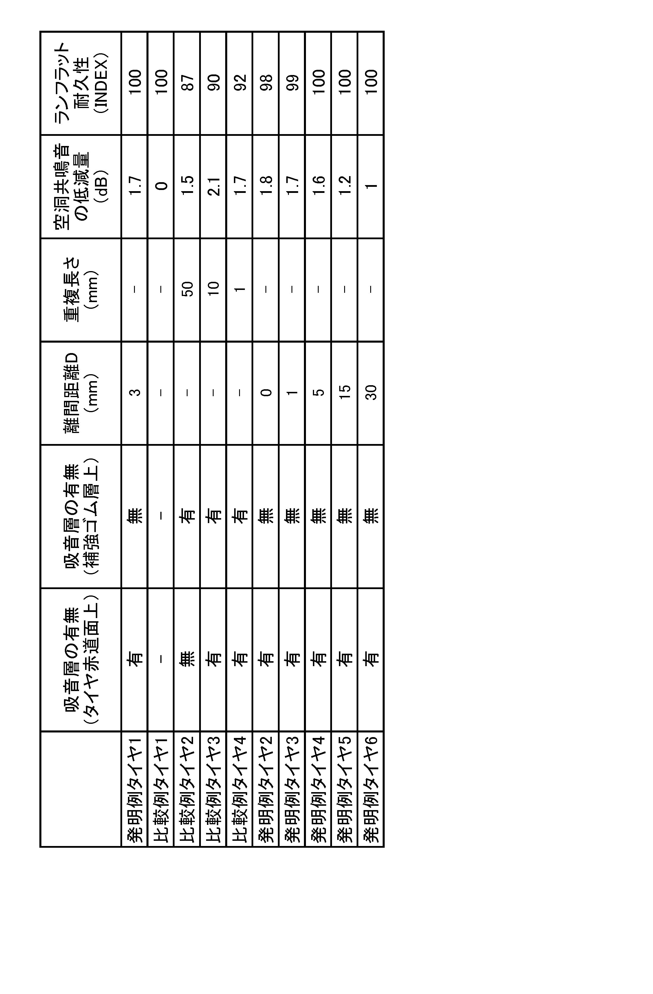
- Inventive example tires and comparative example tires were produced on the basis of the specifications shown in Table 1 to evaluate the reduction effect of cavity resonance noise and the durability during run flat running.
- Inventive example tire 1 is a tire having reinforcing rubber layer 4 in side wall portion 2 shown in FIG. 1, wherein sound absorbing layer 8 is provided on at least a part of the inner peripheral surface of the tire, and sound absorbing layer 8 The tire is not laminated on the reinforcing rubber layer 4.
- the separation distance D between the reinforcing rubber layer 4 and the sound absorbing layer 8 is 3.0 mm.
- the comparative tire 1 is the same tire as the inventive tire 1 except that the sound absorbing layer 8 is not provided.
- the comparative example tire 2 is the same tire as the inventive example tire except that the sound absorbing layer is provided, but the whole of the sound absorbing layer is laminated on the reinforcing rubber layer. That is, in the sound absorbing layer of the comparative example tire 2, two sound absorbing layers having a half length along the inner circumferential surface of the sound absorbing layer 8 of the example tire 1 are respectively provided on one sidewall portion. They are disposed on the provided reinforcing rubber layer and on the reinforcing rubber layer provided on the other sidewall portion.
- the “overlapping length” of Comparative Example tire 2 described in Table 1 is the overlapping length of the noise control layer and the reinforcing rubber layer in one sidewall portion, and in the other sidewall portion. Also, the noise suppressing layer is similarly overlapped on the reinforcing rubber layer.
- the comparative tires 3 and 4 each have a sound absorbing layer, and are similar to the inventive tire 1 except that a part of the sound absorbing layer is laminated on the reinforcing rubber layer. That is, the sound absorbing layer in Comparative Example tires 3 and 4 is wider in the tire width direction than the sound absorbing layer 8 in Inventive Example tire 1, and both ends of the sound absorbing layer are on the reinforcing rubber layer provided in the sidewall portion. It is stacked.
- the overlapping length of the sound absorbing layer and the reinforcing rubber layer in the comparative example tire 3 along the inner peripheral surface of the tire is 10 mm, and the overlapping length in the comparative example tire 4 is 1 mm.
- the “overlap length” of Comparative Example tires 3 and 4 described in Table 1 is the overlap length with the reinforcing rubber layer at one end in the tire width direction of the noise control layer, and The other end in the tire width direction also overlaps the reinforcing rubber layer in the same manner.
- Inventive Example tires 2 to 6 are the same as Inventive Example tire 1 except that the separation distance D between the reinforcing rubber layer 4 and the noise suppressing layer 8 along the inner circumferential surface of the tire is different.
- Each test tire is mounted on a rim (16 x 6.5 J), filled with an internal pressure of 250 kPa (equivalent pressure), mounted on a drum tester equipped with an iron drum having a diameter of 1.7 m and having an iron plate surface. . Rolled at a constant speed under the conditions of 0 kN and a speed of 60 km / h. At that time, each test tire is measured by measuring the peak value of the frequency corresponding to the cavity resonance sound from the frequency spectrum obtained by measuring the vertical tire axial force (Fz) using the wheel force meter. Cavity resonance sound was measured. The results are shown in Table 1 as the reduction amount (dB) of the cavity resonance sound from the peak value of the cavity resonance sound generated in the comparative example tire 1. As the numerical value is larger, it means that the reduction amount of the cavity resonance sound is larger.
- Bead part 2 Side wall part 3: Tread part 4: Reinforcing rubber layer 5: Bead core 6: 6: Carcass 7, 72: Inner liner 8: Noise layer 9: Belt 10, 20 A: tire 11: circumferential groove 2 E: tire radial inner end of sidewall portion 3 E: tire lateral outer end of tread portion 4 E: tire radial outer end of reinforced rubber layer 8 E: tire of sound absorbing layer Width direction outer end, W3: Tire width direction length along the tire inner circumferential surface of the tread portion, W72: Tire width direction length along the tire inner circumferential surface of the inner liner, W8: along the tire inner circumferential surface of the sound absorbing layer Tire width direction length, W9: Belt width, CL: Tire equatorial plane, D: Separation distance, R: Overlap distance, TE: Tread contact edge
Landscapes
- Engineering & Computer Science (AREA)
- Mechanical Engineering (AREA)
- Tires In General (AREA)
Abstract
一対のビード部と、該ビード部のタイヤ径方向外側に配置された一対のサイドウォール部と、該サイドウォール部間に配置されたトレッド部と、を有し、前記サイドウォール部に補強ゴム層を備えるタイヤであって、前記補強ゴム層が、前記サイドウォール部から前記トレッド部の少なくとも一部に亘って延在するとともに、前記タイヤの内周面の少なくとも一部を覆う、制音層を備え、該制音層が、前記補強ゴム層上に積層されていない。
Description
本発明はタイヤに関する。
従来、パンク等によってタイヤ内圧が低下しても、タイヤが荷重支持能力を失うことなくある程度の距離を安全に走行することが可能なタイヤ、所謂ランフラットタイヤとして、タイヤのサイドウォール部に断面三日月状の補強ゴム層を配設した、サイド補強型のランフラットタイヤがある。
このランフラットタイヤは、通常走行時には荷重をタイヤ内圧で支持し、一方、パンク走行時には荷重を補強ゴム層で肩代わりして支持する。このため、タイヤのパンク時にタイヤ内部の空気圧が急激に低下しても、車輌の挙動に急激な変化が生じないので安定した走行が可能であり、また、慌てた運転手による誤ったハンドル操作の危険性を低減することができる(例えば、特許文献1)。
また、一般に、車輌の走行中にトレッド部が路面の凹凸に衝接して振動すると、タイヤ内腔に充填された気体が空洞共鳴することが知られている。この空洞共鳴音は、タイヤに起因する騒音の一つであり、その共鳴周波数の多くが180~300Hzの範囲にある。空洞共鳴音が車室内に伝達されると、他の周波数帯域の騒音とは異なり、鋭く高いピーク値をとるため、車室内の乗員にとって耳障りな騒音となる。
このような空洞共鳴音を低減する方途としては、例えば、インナーライナーのタイヤ内腔側に、スポンジ等からなる制音層を設ける技術が知られている(例えば、特許文献2)。
しかしながら、サイドウォール部に補強ゴム層を有する、サイド補強型のランフラットタイヤにおいては、該補強ゴム層を具備しないタイヤに比しタイヤの負荷転動時における発熱量が増加する。そのため、サイド補強型のランフラットタイヤにおいて、空洞共鳴音を低減するべく上述の制音層を設けた場合、タイヤの放熱性が低下し、タイヤの耐久性、特には、補強ゴム層における発熱量が特に増加するランフラット走行時のタイヤの耐久性が低下する虞があった。また、ランフラットタイヤにおいては、ランフラット走行時の操縦安定性を向上させることも望まれている。
そこで、本発明は、空洞共鳴音を低減しつつも、ランフラット走行時におけるタイヤの耐久性及び操縦安定性を向上させた、タイヤを提供することを目的とする。
本発明のタイヤは、一対のビード部と、該ビード部のタイヤ径方向外側に配置された一対のサイドウォール部と、該サイドウォール部間に配置されたトレッド部と、を有し、前記サイドウォール部に補強ゴム層を備えるタイヤであって、前記補強ゴム層が、前記サイドウォール部から前記トレッド部の少なくとも一部に亘って延在するとともに、前記タイヤの内周面の少なくとも一部を覆う、制音層を備え、該制音層が、前記補強ゴム層上に積層されていないこと、を特徴とする。
なお、「制音層が、補強ゴム層上に積層」とは、制音層が補強ゴム層に直接固着されているか、又は、該制音層が補強ゴム層上に、他の構成部材を介して間接的に固着されていることを意味する。制音層が補強ゴム層上に間接的に固着されている場合における、「補強ゴム層上」とは、該補強ゴム層の延在領域に対応する、タイヤの内周面上を意味する。
また、本明細書において、「ビード部」とは、タイヤのビードトウから、該タイヤに組み付けるリムの離反点に至る領域をいう。より詳細には、ビードトウと、リムの離反点において引いたタイヤ外表面の法線と、の間に延在する領域をいう。
また、本明細書において、「サイドウォール部」とは、タイヤに組み付けるリムの離反点からトレッド接地端に至る領域をいう。より詳細には、リムの離反点において引いたタイヤ外表面の法線と、トレッド接地端において引いたタイヤ外表面の法線と、の間に延在する領域をいう。なお、「トレッド接地端」とは、トレッド踏面(リムに組み付けるとともに所定の内圧を充填したタイヤを、最大負荷荷重を負荷した状態で転動させた際に、路面と接触することになる、タイヤの全周に亘る外周面)のタイヤ幅方向両端をいう。
また、本明細書において、「トレッド部」とは、トレッド接地端間の領域をいう。より詳細には、一方のトレッド接地端において引いたタイヤ外表面の法線と、他方のトレッド接地端において引いたタイヤ外表面の法線と、の間に延在する領域をいう。
なお、上記の「リム」とは、タイヤが生産され、使用される地域に有効な産業規格であって、日本ではJATMA(日本自動車タイヤ協会)のJATMA YEAR BOOK、欧州ではETRTO (The European Tyre and Rim Technical Organisation)のSTANDARDS MANUAL、米国ではTRA (The Tire and Rim Association, Inc.)のYEAR BOOK等に記載されているまたは将来的に記載される、適用サイズにおける標準リム(ETRTOのSTANDARDS MANUALではMeasuring Rim、TRAのYEAR BOOKではDesign Rim)を指す(すなわち、上記の「リム」には、現行サイズに加えて将来的に上記産業規格に含まれ得るサイズも含む。「将来的に記載されるサイズ」の例としては、ETRTOのSTANDARDS MANUAL 2013年度版において「FUTURE DEVELOPMENTS」として記載されているサイズを挙げることができる。)が、上記産業規格に記載のないサイズの場合は、タイヤのビード幅に対応した幅のリムをいう。
また、「所定の内圧」とは、上記のJATMA YEAR BOOK等に記載されている、適用サイズ・プライレーティングにおける単輪の最大負荷能力に対応する空気圧(最高空気圧)をいい、上記産業規格に記載のないサイズの場合は、「所定の内圧」は、タイヤを装着する車両ごとに規定される最大負荷能力に対応する空気圧(最高空気圧)をいうものとする。さらに、「最大負荷荷重」とは、上記最大負荷能力に対応する荷重をいうものとする。なお、ここでいう空気は、窒素ガス等の不活性ガスその他に置換することも可能である。
また、「所定の内圧」とは、上記のJATMA YEAR BOOK等に記載されている、適用サイズ・プライレーティングにおける単輪の最大負荷能力に対応する空気圧(最高空気圧)をいい、上記産業規格に記載のないサイズの場合は、「所定の内圧」は、タイヤを装着する車両ごとに規定される最大負荷能力に対応する空気圧(最高空気圧)をいうものとする。さらに、「最大負荷荷重」とは、上記最大負荷能力に対応する荷重をいうものとする。なお、ここでいう空気は、窒素ガス等の不活性ガスその他に置換することも可能である。
また、本明細書において後述する、「基準状態」とは、タイヤをリムに組み付け、所定の内圧を充填し、無負荷とした状態を指す。
本発明によれば、空洞共鳴音を低減しつつも、ランフラット走行時におけるタイヤの耐久性及び操縦安定性を向上させることができる。
以下に、図面を参照しながら、本発明に係るタイヤの実施形態を例示説明する。
図1は、本発明の一実施形態に係るタイヤ10の半部のタイヤ幅方向断面を示す、部分断面図である。なお、本実施形態では、図示しないタイヤ10の半部においても、図示するタイヤ10の半部と同一の構成を有している。
本実施形態に係るタイヤ10は、一対のビード部1と、該ビード部1の径方向外側に配置された一対のサイドウォール部2と、該サイドウォール部2間に配置されたトレッド部3と、を有し、該サイドウォール部2のそれぞれに、本実施形態では断面三日月状の補強ゴム層4を備えている。より詳細に、タイヤ10は、一対のビード部1のそれぞれに配置されたビードコア5間にトロイダル状に跨る、カーカス6と、該カーカス6よりもタイヤの内周側にて該ビードコア5間にトロイダル状に跨り、タイヤ10の内周面をなす、インナーライナー7と、を備え、補強ゴム層4が、該カーカス6と該インナーライナー7との間に配置されている。
すなわち、本実施形態におけるインナーライナー7は、一方のビード部1のビードトウ付近から他方のビード部1のビードトウ付近に亘って、タイヤの内周面のほぼ全域に亘って延在している。従って、タイヤ10のサイドウォール部2では、タイヤ10の内周側から、インナーライナー7と、補強ゴム層4と、カーカス6と、がこの順に積層されている。
また、本実施形態における補強ゴム層4は、サイドウォール部2のタイヤ径方向内側端縁2E付近からタイヤ径方向外側に、該サイドウォール部2のタイヤ径方向領域に亘って延び、本実施形態では、トレッド部3の少なくとも一部に亘って延びている。すなわち、本実施形態における補強ゴム層4は、トレッド部3のタイヤ幅方向外側端縁3Eよりもタイヤ幅方向内側にて終端している。
なお、補強ゴム層4は、タイヤ周方向に亘って連続し、円環状に延在している。
なお、補強ゴム層4は、タイヤ周方向に亘って連続し、円環状に延在している。
また、本実施形態に係るタイヤ10は、タイヤの内周面の少なくとも一部(本実施形態では、トレッド部3の内周面の、タイヤ赤道面CLを含む領域)に、本実施形態では、多孔質材料からなる制音層8を備えている。制音層8は、該制音層8のタイヤ幅方向端8Eが、補強ゴム層4のタイヤ径方向外側端4Eよりもタイヤ幅方向内側、すなわち、タイヤ赤道面CL側に位置するように配置されている。
このように、本実施形態に係るタイヤ10では、制音層8が、補強ゴム層4上に積層しないように配置されている。
このように、本実施形態に係るタイヤ10では、制音層8が、補強ゴム層4上に積層しないように配置されている。
以上のように、本実施形態に係るタイヤ10では、タイヤの内周面の少なくとも一部を覆う、制音層8を設けているため、車両走行中の空洞共鳴音を低減させることができる。
また、該制音層8が、補強ゴム層4上に積層されていないため、当該制音層8によって補強ゴム層4における放熱が抑制されず、該補強ゴム層4に蓄熱され難い。従って、サイド補強型のランフラットタイヤにおいて特に顕著となる、補強ゴム層4における温度上昇が抑制されるため、ランフラット走行時におけるタイヤの耐久性を向上させることができる。
また、該制音層8が、補強ゴム層4上に積層されていないため、当該制音層8によって補強ゴム層4における放熱が抑制されず、該補強ゴム層4に蓄熱され難い。従って、サイド補強型のランフラットタイヤにおいて特に顕著となる、補強ゴム層4における温度上昇が抑制されるため、ランフラット走行時におけるタイヤの耐久性を向上させることができる。
なお、本実施形態における制音層8は、スポンジ材により構成されている。スポンジ材は、海綿状の多孔構造体であり、例えば、ゴムや合成樹脂を発泡させた連続気泡を有する所謂スポンジを含む。また、スポンジ材は、上述のスポンジの他に、動物繊維、植物繊維又は合成繊維等を絡み合わせて一体に連結したウエブ状のものを含む。なお、上述の「多孔構造体」は、連続気泡を有する構造体に限らず、独立気泡を有する構造体も含む意味である。
上述のようなスポンジ材は、表面や内部に形成される空隙が振動する空気の振動エネルギーを熱エネルギーに変換する。これにより、タイヤ内腔での空洞共鳴が抑制され、その結果、ロードノイズを低減することができる。またスポンジ材は、収縮、屈曲等の変形が容易である。そのため、スポンジ材で形成された制音層8がトレッドの内周面上に積層されていても、車両走行時のタイヤの変形に実質的な影響を与えない。つまり、トレッドの内周面上に制音層8を積層する構成としても、操縦安定性等に悪影響を与え難い。
スポンジ材の材料としては、例えば、エーテル系ポリウレタンスポンジ、エステル系ポリウレタンスポンジ、ポリエチレンスポンジなどの合成樹脂スポンジ、クロロプレンゴムスポンジ(CRスポンジ)、エチレンプロピレンゴムスポンジ(EPDMスポンジ)、ニトリルゴムスポンジ(NBRスポンジ)などのゴムスポンジが挙げられる。制音性、軽量性、発泡の調節可能性、耐久性などの観点を考慮すれば、エーテル系ポリウレタンスポンジを含むポリウレタン系又はポリエチレン系等のスポンジを用いることが好ましい。
なお、制音層8を構成する材料は、空洞共鳴エネルギーの緩和、吸収、別のエネルギー(例えば熱エネルギー)への変換、等によって、空洞共鳴エネルギーを低減するように制御できるものであればよく、上述したスポンジ材に限られるものではない。
また、スポンジ材の比重は、タイヤ重量の増加と空洞共鳴を抑える効果との両方のバランスを考慮し、0.005~0.06とすることが好ましく、0.01~0.04とすることがより好ましく、0.01~0.03とすることが特に好ましい。
更に、制音層8の体積は、タイヤ内腔の全体積の0.4%~20%とすることが好ましい。タイヤ内腔の全体積に対して制音層8の体積を0.4%以上確保することにより、所望量(例えば2dB以上)の空洞共鳴エネルギーの低減効果を実現し易い。制音層8は、タイヤ内腔の全体積の1%以上とすることがより好ましく、2%以上とすることが更に好ましく、4%以上とすることが特に好ましい。その一方、制音層8の体積がタイヤ内腔の全体積の20%を超えるように構成しても空洞共鳴エネルギーの低減効果の向上が期待できない。むしろ、タイヤをリムに組み付けてなるタイヤ組立体の重量バランスを悪化させる可能性がある。このような観点より、制音層8の体積は、タイヤ内腔の全体積の16%以下とすることがより好ましく、10%以下とすることが特に好ましい。なお、上述の体積比は、制音層8の数に関係しない。つまり、制音層8が複数ある場合には、複数の制音層8全ての体積の和が上述の体積比の関係を満足すれば、同様の効果を得ることができる。
なお、本発明において、補強ゴム層4のタイヤ径方向外側端4Eと、吸音層8のタイヤ幅方向外側端8Eと、が重複する場合、より具体的には、補強ゴム層4のタイヤ径方向外側端4Eに引いたタイヤ径方向線(図中、二点鎖線で示す)上に、吸音層8のタイヤ幅方向外側端8Eが位置している場合については、吸音層8が補強ゴム層4上に積層されていないものとする。
また、本発明では、上述のとおり、吸音層8が補強ゴム層8上に積層されていないことが肝要であり、すなわち、吸音層8が補強ゴム層8上に直接固着されていないこと、又は、該制音層8が補強ゴム層上に、例えば、インナーライナー7等の他の構成部材を介して間接的に固着されていないことが、補強ゴム層4における放熱を抑制しない観点から肝要である。従って、例えば、吸音層8の一部が、補強ゴム層4との間に空間を介して該補強ゴム層4上を覆っていてもよい。この場合、当該空間を介して、補強ゴム層4に生じた熱が放熱される。
また、本実施形態に係るタイヤ10では、補強ゴム層4が、サイドウォール部2からトレッド部3の少なくとも一部に亘って延在している。このように、補強ゴム層4が、サイドウォール部2内にて終端せず、トレッド部3のタイヤ幅方向外側端3Eよりもタイヤ幅方向内側まで延長している場合、ランフラット走行時における、タイヤ径方向及びタイヤ幅方向の剛性がより高まるため、ランフラット走行時における操縦安定性が向上する。
しかしながら、補強ゴム層4を、サイドウォール部2のみならず、トレッド部3の少なくとも一部に亘って延在させる場合、タイヤ10に占める補強ゴム層4の体積が相対的に大きくなり、タイヤ10の発熱量も増加する。
そこで、特に、補強ゴム層4をトレッド部3の少なくとも一部に亘って延在させる場合、制音層8を補強ゴム層4に積層させないことは勿論、タイヤの基準状態における、タイヤ幅方向断面視で、該制音層8と補強ゴム層4とが、タイヤの内周面に沿って3.0mm以上15.0mm以下離間していることが好ましい。
すなわち、補強ゴム層4のタイヤ径方向外側端4Eと、制音層8のタイヤ幅方向外側端8Eと、がタイヤの内周面に沿って3.0mm以上15.0mm以下離間していることが好ましい。
すなわち、補強ゴム層4のタイヤ径方向外側端4Eと、制音層8のタイヤ幅方向外側端8Eと、がタイヤの内周面に沿って3.0mm以上15.0mm以下離間していることが好ましい。
補強ゴム層4と制音層8との離間距離Dが3.0mm以上であれば、補強ゴム層4と、該補強ゴム層4における放熱の妨げとなる制音層8と、が十分に離間して、補強ゴム層4における放熱がより抑制されにくくなるため、ランフラット走行時にけるタイヤの耐久性をさらに向上させることができる。
離間距離Dが15.0mm以下であれば、制音層8の体積及び表面積を十分に確保して、空洞共鳴音をより十分に低減することができる。
離間距離Dが15.0mm以下であれば、制音層8の体積及び表面積を十分に確保して、空洞共鳴音をより十分に低減することができる。
また、補強ゴム層4における発熱量は、該補強ゴム層4の体積に比例する。そこで、本実施形態では、基準状態におけるタイヤ幅方向断面視で、補強ゴム層4と制音層8との離間距離D(mm)を、補強ゴム層4の断面積(mm2)で除した値が、0.006/mm以上であることが、ランフラット走行時におけるタイヤの耐久性をさらに向上させる観点からこのましい。
また、本実施形態に係るタイヤ10では、制音層8が、トレッド部3の内周面のタイヤ赤道面CLを含む領域に延在しており、基準状態における、タイヤ赤道面CLに沿うタイヤ周方向断面視で、制音層8のタイヤの内周面に沿う長さが、該タイヤの内周面の周長の、0.7倍以上であることが好ましい。
制音層8を、タイヤの赤道面CLを含む領域に配置すれば、該制音層8を比較的広幅に配置することができ、該吸音層8の体積を増すことができる。さらには、上記のタイヤ周方向断面視で、制音層8のタイヤの内周面に沿う長さを、該タイヤの内周面の周長の、0.7倍以上とすれば、制音層8の体積をさらに増すことができるため、空洞共鳴音をより確実に低減することができる。
制音層8を、タイヤの赤道面CLを含む領域に配置すれば、該制音層8を比較的広幅に配置することができ、該吸音層8の体積を増すことができる。さらには、上記のタイヤ周方向断面視で、制音層8のタイヤの内周面に沿う長さを、該タイヤの内周面の周長の、0.7倍以上とすれば、制音層8の体積をさらに増すことができるため、空洞共鳴音をより確実に低減することができる。
ただし、本発明では、制音層が補強ゴム層上に積層されていない限り、該制音層を、タイヤの赤道面CLの一方側と他方側とに分割して配置することができ、また、該制音層を、タイヤ周方向に連続的に又は断続的に配置することができる。
また、本実施形態に係るタイヤ10では、上記基準状態におけるタイヤ幅方向断面視で、制音層8のタイヤの内周面に沿う長さW8が、トレッド部3のタイヤの内周面に沿う長さW3の、0.6以上0.9以下である。すなわち、比W8/W3が、0.6以上0.9以下である。
0.6以上であれば、吸音層8が比較的広幅に配置されて、該吸音層8の体積及び表面積が増加するため、空洞共鳴音をより十分に低減することができる。
0.9以下であれば、トレッド部3のタイヤ内表面における放熱を妨げ難いため、車両走行中におけるタイヤ全体の温度上昇が抑制される。従って、ランフラット走行時においても、タイヤの耐久性をさらに向上させることができる。
0.9以下であれば、トレッド部3のタイヤ内表面における放熱を妨げ難いため、車両走行中におけるタイヤ全体の温度上昇が抑制される。従って、ランフラット走行時においても、タイヤの耐久性をさらに向上させることができる。
なお、図1において、吸音層8は、断面長方形であるが、該吸音層8の断面形状は、三角形、台形、円形、楕円形、又はこれらの組合せ等の、任意の形状とすることができる。
また、吸音層8の内周側の面を、例えば、波状、ジグザグ状、若しくは、階段状等の凹凸形状、又は、複数の突起を有する凹凸形状等とすれば、該吸音層8の表面積が増すため、空洞共鳴音を効果的に低減することができる。
また、吸音層8の内周側の面を、例えば、波状、ジグザグ状、若しくは、階段状等の凹凸形状、又は、複数の突起を有する凹凸形状等とすれば、該吸音層8の表面積が増すため、空洞共鳴音を効果的に低減することができる。
また、本実施形態に係るタイヤ10は、トレッド部3におけるカーカス6の外周側に、ベルト9を備え、本実施形態において、該ベルト9は、タイヤ周方向に対して傾斜して延びる複数本のコードをゴム被覆してなる、少なくとも1層(本実施形態では、2層)の傾斜ベルト層と、該傾斜ベルト層のタイヤ径方向外側に配置され、タイヤ周方向に沿って延びる複数本のコードをゴム被覆してなる、少なくとも1層(本実施形態では、1層)の周方向ベルト層と、から構成されている。本実施形態において、該ベルト9は、タイヤ赤道面CLからタイヤ幅方向両側に延び、トレッド部3のタイヤ幅方向外側端3Eよりもタイヤ幅方向外側にて終端している。
しかしながら、本発明に係るタイヤにおいて、ベルトの構成はこれに限定されない。
しかしながら、本発明に係るタイヤにおいて、ベルトの構成はこれに限定されない。
また、本実施形態においては、図示しないタイヤ10の半部が、図示するタイヤ10の半部と同一の構成を有しているが、本発明においては、タイヤの少なくとも一方の半部において、吸音層8が補強ゴム層4上に積層されていなければよく、タイヤの他方の半部における、吸音層8と補強ゴム層4との位置関係については限定されない。
しかしながら、空洞共鳴音の低減効果、及び、ランフラット走行時におけるタイヤの耐久性向上効果をより確実に得る観点から言えば、タイヤの一方の半部及び他方の半部の双方において、吸音層8が、補強ゴム層4上に積層されていないことが好ましい。
しかしながら、空洞共鳴音の低減効果、及び、ランフラット走行時におけるタイヤの耐久性向上効果をより確実に得る観点から言えば、タイヤの一方の半部及び他方の半部の双方において、吸音層8が、補強ゴム層4上に積層されていないことが好ましい。
つぎに、図2を参照して、本発明の他の実施形態に係るタイヤ20について説明する。図2は、本発明の他の実施形態に係るタイヤ20の半部のタイヤ幅方向断面を示す、部分断面図である。
タイヤ20は、基準状態におけるタイヤ幅方向断面視で、インナーライナー72のタイヤ幅方向端72Eがサイドウォール部2にて終端していること以外は、図1に示す先の実施形態に係るタイヤ10と同一の構成を有している。従って、タイヤ10と同一の構成については、同一の符号を付してその説明を省略する。
タイヤ20は、基準状態におけるタイヤ幅方向断面視で、インナーライナー72のタイヤ幅方向端72Eがサイドウォール部2にて終端していること以外は、図1に示す先の実施形態に係るタイヤ10と同一の構成を有している。従って、タイヤ10と同一の構成については、同一の符号を付してその説明を省略する。
本実施形態に係るタイヤ20におけるインナーライナー72は、一対のサイドウォール部2のタイヤ径方向外側領域間に跨って延びている。すなわち、本実施形態では、インナーライナー72が、タイヤ赤道面CLを中心として、該タイヤ赤道面CLからタイヤ幅方向両外側にトレッド部3のタイヤ幅方向領域に亘って延び、さらに、トレッド部3のタイヤ幅方向外側端3Eよりもタイヤ幅方向外側にて終端している。本実施形態におけるインナーライナー72のタイヤ幅方向端72Eは、トレッド接地端TEよりもタイヤ幅方向外側であり、かつタイヤ20の最大幅位置よりもタイヤ径方向外側に位置している。
従って、本実施形態におけるインナーライナー72は、サイドウォール部2において、該サイドウォール部2に配置された補強ゴム層4のタイヤ径方向外側部分にのみ積層されている。すなわち、補強ゴム層4の当該タイヤ径方向外側部分においては、タイヤの内周側から、インナーライナー72と、補強ゴム層4と、カーカス6と、がこの順に積層されているが、該補強ゴム層3の当該部分よりもタイヤ径方向内側では、タイヤの内周側から、補強ゴム層4と、カーカス6と、がこの順に積層されており、インナーライナー72は積層されていない。
このように、本実施形態に係るタイヤ20では、インナーライナー72の延在領域では該インナーライナー72がタイヤ20の内周面をなしているが、該インナーライナー72の非延在領域、例えば、サイドウォール部2のタイヤ径方向内側領域では、補強ゴム層4がタイヤ20の内周面をなしている。
また、本実施形態に係るタイヤ20では、上述した先の実施形態に係るタイヤ10と同様に、吸音層8が、補強ゴム層4上に積層されていない。
このように、タイヤ20では、吸音層8が、補強ゴム層4上に積層されていないことに加えて、インナーライナー72が、補強ゴム層4上にタイヤ径方向に亘って積層されていない。すなわち、インナーライナー72が、補強ゴム層4の一部にのみ積層されている。
このように、タイヤ20では、吸音層8が、補強ゴム層4上に積層されていないことに加えて、インナーライナー72が、補強ゴム層4上にタイヤ径方向に亘って積層されていない。すなわち、インナーライナー72が、補強ゴム層4の一部にのみ積層されている。
この構成では、補強ゴム層4の一部がタイヤの内腔に露出しており、該補強ゴム層4における放熱がより効率的に行われるため、ランフラット走行時におけるタイヤの耐久性をより高次に向上させることができる。
また、一般に、インナーライナーには、タイヤの他の部分に比し発熱性が高い(tanδが大きい)ゴムが使用されるので、該インナーライナーの配設領域を縮小することにより、ランフラット走行時は勿論のこと、通常の車両走行におけるタイヤの発熱量を低減できる観点からも、タイヤの耐久性をさらに向上させることができる。
また、一般に、インナーライナーには、タイヤの他の部分に比し発熱性が高い(tanδが大きい)ゴムが使用されるので、該インナーライナーの配設領域を縮小することにより、ランフラット走行時は勿論のこと、通常の車両走行におけるタイヤの発熱量を低減できる観点からも、タイヤの耐久性をさらに向上させることができる。
なお、本実施形態に係るタイヤ20のように、サイドウォール部2に補強ゴム層4を備える場合、インナーライナー72をタイヤの内周面の全域に亘って配置せずとも、当該補強ゴム層4によって内圧が保持される。
また、本実施形態に係るタイヤ20では、基準状態におけるタイヤ幅方向断面視で、インナーライナー72と、トレッド部3におけるカーカス6のタイヤ径方向外側に配置された、ベルト9と、が以下の関係式を満たしていることが好ましい。すなわち、タイヤ幅方向断面視における、インナーライナー72のタイヤの内周面に沿う長さW72と、ベルト9のベルト幅W9と、が関係式「W9≦W72≦W9+20mm」を満たしていることが好ましい。
インナーライナー72のタイヤの内周面に沿う長さW72が、ベルト9のベルト幅W9以上であれば、タイヤの内圧保持性を好適に維持し、また、ベルト9の耐久性を保持することができる。
また、インナーライナー72のタイヤの内周面に沿う長さW72が、ベルト幅W9に20mmを加えた長さ以下であれば、インナーライナー72に起因する不要な発熱を抑制することができる。
また、インナーライナー72のタイヤの内周面に沿う長さW72が、ベルト幅W9に20mmを加えた長さ以下であれば、インナーライナー72に起因する不要な発熱を抑制することができる。
なお、本実施形態では、タイヤの内周面に沿うインナーライナー72と補強ゴム層4との重複長さRは、該補強ゴム層4のタイヤの内周面に沿う長さのおよそ25%であるが、該重複長さRを、20%以下、15%以下、10%以下、等任意に決めることができる。
なお、本実施形態に係るタイヤ20における、補強ゴム層4の好適な配設範囲、吸音層8の好適な配設範囲及びタイヤ幅方向長さ、吸音層8の好適な材料・比重・タイヤ内腔の全体積に占める割合、吸音層8の好適な断面形状、補強ゴム層4と吸音層8との好適な離間距離等は、先の実施形態に係るタイヤ10において記載した通りである。
また、図1,2に示すタイヤ10,20の半部においては、トレッド部3の踏面Tに、2本の周方向溝11が設けられているが、本発明に係るタイヤは、当該形態に限定されず、タイヤの半部に1本、3本又はそれ以上の周方向溝を備えることができ、又は備えないことができる。さらに、所期する性能に応じて、幅方向溝やサイプ等の任意の溝等を設けることができる。
以下に、本発明の実施例について説明するが、本発明は下記の実施例に何ら限定されるものではない。
発明例タイヤおよび比較例タイヤ(ともに、タイヤサイズは205/55R16)を表1に示す仕様のもと試作し、空洞共鳴音の低減効果及びランフラット走行時の耐久性を評価した。
発明例タイヤ1は、図1に示す、サイドウォール部2に補強ゴム層4を備えるタイヤであって、タイヤの内周面の少なくとも一部に、吸音層8を備え、該吸音層8が、補強ゴム層4上に積層されていないタイヤである。なお、発明例タイヤ1における、補強ゴム層4と吸音層8との離間距離Dは、3.0mmである。
比較例タイヤ1は、吸音層8を備えないこと以外は、発明例タイヤ1と同様のタイヤである。
比較例タイヤ2は、吸音層を備えるが、該吸音層の全体が補強ゴム層上に積層されていること以外は、発明例タイヤと同様のタイヤである。すなわち、比較例タイヤ2における吸音層は、発明例タイヤ1における吸音層8の、タイヤの内周面に沿う長さの半分の長さを有する2つの吸音層がそれぞれ、一方のサイドウォール部に設けられた補強ゴム層上と、他方のサイドウォール部に設けられた補強ゴム層上と、に配置されている。なお、表1中に記載される、比較例タイヤ2の「重複長さ」は、一方のサイドウォール部における、制音層と補強ゴム層との重複長さであり、他方のサイドウォール部においても、制音層が補強ゴム層上に同様に重複している。
比較例タイヤ3,4は、吸音層を備えるが、該吸音層の一部が補強ゴム層上に積層されていること以外は、発明例タイヤ1と同様のタイヤである。すなわち、比較例タイヤ3,4における吸音層は、発明例タイヤ1における吸音層8よりもタイヤ幅方向に広幅であり、該吸音層の両端部が、サイドウォール部に設けた補強ゴム層上に積層されている。
なお、比較例タイヤ3における、吸音層と補強ゴム層とのタイヤの内周面に沿う重複長さは、10mmであり、比較例タイヤ4における同重複長さは、1mmである。なお、表1中に記載される、比較例タイヤ3,4の「重複長さ」は、制音層のタイヤ幅方向一方端における補強ゴム層との重複長さであり、該制音層のタイヤ幅方向他方端もまた同様に補強ゴム層上に重複している。
なお、比較例タイヤ3における、吸音層と補強ゴム層とのタイヤの内周面に沿う重複長さは、10mmであり、比較例タイヤ4における同重複長さは、1mmである。なお、表1中に記載される、比較例タイヤ3,4の「重複長さ」は、制音層のタイヤ幅方向一方端における補強ゴム層との重複長さであり、該制音層のタイヤ幅方向他方端もまた同様に補強ゴム層上に重複している。
発明例タイヤ2~6は、補強ゴム層4と制音層8との、タイヤの内周面に沿う離間距離Dが異なること以外は、発明例タイヤ1と同様のタイヤである。
[空洞共鳴音の低減効果]
各供試タイヤをリム(16×6.5J)に装着し、内圧250kPa(相当圧)を充填し、鉄板表面を有する直径1.7mの鉄製ドラムを備えるドラム試験機に取り付け、タイヤ負荷質量5.0kN、速度60km/hの条件のもと定速で転動させた。その際に、ホイール分力計を用いて上下方向タイヤ軸力(Fz)を測定することにより得られる周波数スペクトルから、空洞共鳴音に対応する周波数のピーク値を測定することにより、各供試タイヤの空洞共鳴音を測定した。
その結果を、表1に、比較例タイヤ1で発生した空洞共鳴音のピーク値からの低減量を、空洞共鳴音の低減量(dB)として示す。数値が大きいほど、空洞共鳴音の低減量が大きいことを意味している。
[ランフラット耐久性]
ドラム試験機にてLI(Load Index)に応じた最大負荷荷重の65%となる荷重を加え、速度80km/hで走行させ、160km(2時間)を完走条件として、タイヤが故障して走行できなくなるまでの距離を計測した。比較例タイヤ1におけるランフラット耐久性(ランフラット走行時の耐久性)を100として、指数評価した結果を表1に示す。数値が大きいほど、タイヤのランフラット耐久性が良好であることを示す。
ドラム試験機にてLI(Load Index)に応じた最大負荷荷重の65%となる荷重を加え、速度80km/hで走行させ、160km(2時間)を完走条件として、タイヤが故障して走行できなくなるまでの距離を計測した。比較例タイヤ1におけるランフラット耐久性(ランフラット走行時の耐久性)を100として、指数評価した結果を表1に示す。数値が大きいほど、タイヤのランフラット耐久性が良好であることを示す。
表1に示すように、発明例タイヤにおいては、比較例タイヤに比し、空洞共鳴音を低減しつつもランフラット走行時におけるタイヤの耐久性が向上した。
1:ビード部、 2:サイドウォール部、 3:トレッド部、 4:補強ゴム層、 5:ビードコア、 6:カーカス、 7,72:インナーライナー、 8:制音層、 9:ベルト、 10,20:タイヤ、 11:周方向溝、 2E:サイドウォール部のタイヤ径方向内側端、 3E:トレッド部のタイヤ幅方向外側端、 4E:補強ゴム層のタイヤ径方向外側端、 8E:吸音層のタイヤ幅方向外側端、 W3:トレッド部のタイヤ内周面に沿うタイヤ幅方向長さ、 W72:インナーライナーのタイヤ内周面に沿うタイヤ幅方向長さ、 W8:吸音層のタイヤ内周面に沿うタイヤ幅方向長さ、 W9:ベルト幅、 CL:タイヤ赤道面、 D:離間距離、 R:重複距離、 TE:トレッド接地端
Claims (4)
- 一対のビード部と、該ビード部のタイヤ径方向外側に配置された一対のサイドウォール部と、該サイドウォール部間に配置されたトレッド部と、を有し、前記サイドウォール部に補強ゴム層を備えるタイヤであって、
前記補強ゴム層が、前記サイドウォール部から前記トレッド部の少なくとも一部に亘って延在するとともに、
前記タイヤの内周面の少なくとも一部を覆う、制音層を備え、
該制音層が、前記補強ゴム層上に積層されていないこと、を特徴とするタイヤ。 - 前記制音層が、前記トレッド部の内周面のタイヤ赤道面を含む領域に延在しており、
前記タイヤをリムに組み付け、所定の内圧を充填し、無負荷とした、基準状態における、タイヤ赤道面に沿うタイヤ周方向断面視で、前記制音層の前記タイヤの内周面に沿う長さが、該タイヤの内周面の周長の、0.7倍以上である、請求項1に記載のタイヤ。 - 前記基準状態におけるタイヤ幅方向断面視で、前記補強ゴム層と前記制音層とが、前記タイヤの内周面に沿って3.0mm以上15.0mm以下離間している、請求項1又は2に記載のタイヤ。
- 前記基準状態におけるタイヤ幅方向断面視で、前記制音層の前記タイヤの内周面に沿う長さが、前記トレッド部の前記タイヤの内周面に沿う長さの、0.6以上0.9以下である、請求項2又は3に記載のタイヤ。
Priority Applications (3)
| Application Number | Priority Date | Filing Date | Title |
|---|---|---|---|
| EP18839228.6A EP3659829A4 (en) | 2017-07-27 | 2018-06-26 | TIRES |
| CN201880048353.5A CN110944854A (zh) | 2017-07-27 | 2018-06-26 | 轮胎 |
| US16/633,292 US20200139768A1 (en) | 2017-07-27 | 2018-06-26 | Tire |
Applications Claiming Priority (2)
| Application Number | Priority Date | Filing Date | Title |
|---|---|---|---|
| JP2017-145859 | 2017-07-27 | ||
| JP2017145859A JP2019026019A (ja) | 2017-07-27 | 2017-07-27 | タイヤ |
Publications (1)
| Publication Number | Publication Date |
|---|---|
| WO2019021724A1 true WO2019021724A1 (ja) | 2019-01-31 |
Family
ID=65041157
Family Applications (1)
| Application Number | Title | Priority Date | Filing Date |
|---|---|---|---|
| PCT/JP2018/024231 WO2019021724A1 (ja) | 2017-07-27 | 2018-06-26 | タイヤ |
Country Status (5)
| Country | Link |
|---|---|
| US (1) | US20200139768A1 (ja) |
| EP (1) | EP3659829A4 (ja) |
| JP (2) | JP2019026019A (ja) |
| CN (1) | CN110944854A (ja) |
| WO (1) | WO2019021724A1 (ja) |
Cited By (1)
| Publication number | Priority date | Publication date | Assignee | Title |
|---|---|---|---|---|
| WO2021229976A1 (ja) * | 2020-05-15 | 2021-11-18 | 横浜ゴム株式会社 | 空気入りタイヤ |
Families Citing this family (2)
| Publication number | Priority date | Publication date | Assignee | Title |
|---|---|---|---|---|
| JP6910284B2 (ja) * | 2017-12-18 | 2021-07-28 | 株式会社ブリヂストン | 空気入りタイヤ |
| CN112744034A (zh) * | 2020-12-21 | 2021-05-04 | 正新橡胶(中国)有限公司 | 缺气保用轮胎 |
Citations (6)
| Publication number | Priority date | Publication date | Assignee | Title |
|---|---|---|---|---|
| JPS5164203A (ja) * | 1974-10-09 | 1976-06-03 | Goodrich Co B F | |
| JP2015033958A (ja) | 2013-08-09 | 2015-02-19 | 株式会社ブリヂストン | ランフラットタイヤ |
| JP2015147544A (ja) * | 2014-02-07 | 2015-08-20 | 住友ゴム工業株式会社 | 制音具付き空気入りタイヤ及びタイヤ用制音具 |
| JP2016074283A (ja) * | 2014-10-03 | 2016-05-12 | 株式会社ブリヂストン | ランフラットタイヤ |
| DE102015213496A1 (de) * | 2015-07-17 | 2017-01-19 | Continental Reifen Deutschland Gmbh | Fahrzeugluftreifen |
| JP2017065673A (ja) | 2014-10-17 | 2017-04-06 | 住友ゴム工業株式会社 | 空気入りタイヤ、空気入りタイヤの製造方法 |
Family Cites Families (10)
| Publication number | Priority date | Publication date | Assignee | Title |
|---|---|---|---|---|
| JP3645277B2 (ja) * | 1992-12-24 | 2005-05-11 | 株式会社ブリヂストン | 空気入りタイヤ |
| JP3621899B2 (ja) * | 2001-08-28 | 2005-02-16 | 住友ゴム工業株式会社 | 空気入りタイヤとリムとの組立体 |
| JP4330550B2 (ja) * | 2005-04-28 | 2009-09-16 | 住友ゴム工業株式会社 | 空気入りタイヤとリムとの組立体 |
| JP2007091167A (ja) * | 2005-09-30 | 2007-04-12 | Yokohama Rubber Co Ltd:The | 空気入りタイヤ |
| JP2007112395A (ja) * | 2005-10-24 | 2007-05-10 | Sumitomo Rubber Ind Ltd | 空気入りタイヤとリムとの組立体 |
| EP1795378B1 (en) * | 2005-12-08 | 2011-05-25 | Sumitomo Rubber Industries, Ltd. | Pneumatic tire with noise damper |
| JP5528161B2 (ja) * | 2010-03-05 | 2014-06-25 | 株式会社ブリヂストン | タイヤ |
| JP6454472B2 (ja) * | 2014-02-03 | 2019-01-16 | 株式会社ブリヂストン | ランフラットラジアルタイヤ |
| JP6408333B2 (ja) * | 2014-10-03 | 2018-10-17 | 株式会社ブリヂストン | ランフラットタイヤ |
| JP6658035B2 (ja) * | 2016-02-05 | 2020-03-04 | 横浜ゴム株式会社 | 空気入りタイヤ |
-
2017
- 2017-07-27 JP JP2017145859A patent/JP2019026019A/ja not_active Ceased
-
2018
- 2018-06-26 WO PCT/JP2018/024231 patent/WO2019021724A1/ja active Application Filing
- 2018-06-26 CN CN201880048353.5A patent/CN110944854A/zh active Pending
- 2018-06-26 EP EP18839228.6A patent/EP3659829A4/en not_active Withdrawn
- 2018-06-26 US US16/633,292 patent/US20200139768A1/en not_active Abandoned
-
2021
- 2021-08-19 JP JP2021134379A patent/JP2021178637A/ja not_active Ceased
Patent Citations (6)
| Publication number | Priority date | Publication date | Assignee | Title |
|---|---|---|---|---|
| JPS5164203A (ja) * | 1974-10-09 | 1976-06-03 | Goodrich Co B F | |
| JP2015033958A (ja) | 2013-08-09 | 2015-02-19 | 株式会社ブリヂストン | ランフラットタイヤ |
| JP2015147544A (ja) * | 2014-02-07 | 2015-08-20 | 住友ゴム工業株式会社 | 制音具付き空気入りタイヤ及びタイヤ用制音具 |
| JP2016074283A (ja) * | 2014-10-03 | 2016-05-12 | 株式会社ブリヂストン | ランフラットタイヤ |
| JP2017065673A (ja) | 2014-10-17 | 2017-04-06 | 住友ゴム工業株式会社 | 空気入りタイヤ、空気入りタイヤの製造方法 |
| DE102015213496A1 (de) * | 2015-07-17 | 2017-01-19 | Continental Reifen Deutschland Gmbh | Fahrzeugluftreifen |
Non-Patent Citations (1)
| Title |
|---|
| See also references of EP3659829A4 * |
Cited By (1)
| Publication number | Priority date | Publication date | Assignee | Title |
|---|---|---|---|---|
| WO2021229976A1 (ja) * | 2020-05-15 | 2021-11-18 | 横浜ゴム株式会社 | 空気入りタイヤ |
Also Published As
| Publication number | Publication date |
|---|---|
| EP3659829A1 (en) | 2020-06-03 |
| JP2019026019A (ja) | 2019-02-21 |
| EP3659829A4 (en) | 2021-03-17 |
| JP2021178637A (ja) | 2021-11-18 |
| US20200139768A1 (en) | 2020-05-07 |
| CN110944854A (zh) | 2020-03-31 |
Similar Documents
| Publication | Publication Date | Title |
|---|---|---|
| RU2566593C2 (ru) | Пневматическая шина | |
| JP2021178637A (ja) | タイヤ | |
| JP2013112062A (ja) | 制音体付空気入りタイヤ | |
| JP2015120425A (ja) | 空気入りタイヤ | |
| JP2016074282A (ja) | ランフラットタイヤ | |
| JP2003335110A (ja) | 重荷重用空気入りタイヤ | |
| JP2019085063A (ja) | 空気入りタイヤ | |
| US6807996B2 (en) | Pneumatic tire | |
| JP6934354B2 (ja) | タイヤ | |
| WO2019102873A1 (ja) | 空気入りタイヤ | |
| JP2021091367A (ja) | 空気入りタイヤ | |
| JP2013169826A (ja) | 空気入りタイヤ | |
| JP2013184513A (ja) | 空気入りタイヤ | |
| JP7151627B2 (ja) | 空気入りタイヤ | |
| EP4194228A1 (en) | Pneumatic tyre | |
| JP7329106B2 (ja) | 乗用車用空気入りラジアルタイヤ | |
| JP6911560B2 (ja) | 空気入りタイヤ | |
| US20220324270A1 (en) | Tire | |
| JP2023025941A (ja) | ランフラットタイヤ及びランフラットタイヤ・リム組立体 | |
| JP2022120448A (ja) | タイヤ | |
| JP2020121688A (ja) | 空気入りタイヤ | |
| CN115443221A (zh) | 充气轮胎 | |
| JP2019189188A (ja) | 空気入りタイヤ | |
| JP2020121682A (ja) | 空気入りタイヤ | |
| JP2011201364A (ja) | 空気入りタイヤ |
Legal Events
| Date | Code | Title | Description |
|---|---|---|---|
| 121 | Ep: the epo has been informed by wipo that ep was designated in this application |
Ref document number: 18839228 Country of ref document: EP Kind code of ref document: A1 |
|
| NENP | Non-entry into the national phase |
Ref country code: DE |
|
| WWE | Wipo information: entry into national phase |
Ref document number: 2018839228 Country of ref document: EP |
|
| ENP | Entry into the national phase |
Ref document number: 2018839228 Country of ref document: EP Effective date: 20200227 |