WO2019017097A1 - 燃料噴射弁 - Google Patents
燃料噴射弁 Download PDFInfo
- Publication number
- WO2019017097A1 WO2019017097A1 PCT/JP2018/021489 JP2018021489W WO2019017097A1 WO 2019017097 A1 WO2019017097 A1 WO 2019017097A1 JP 2018021489 W JP2018021489 W JP 2018021489W WO 2019017097 A1 WO2019017097 A1 WO 2019017097A1
- Authority
- WO
- WIPO (PCT)
- Prior art keywords
- needle
- fuel
- movable core
- injection valve
- fuel injection
- Prior art date
- Legal status (The legal status is an assumption and is not a legal conclusion. Google has not performed a legal analysis and makes no representation as to the accuracy of the status listed.)
- Ceased
Links
Images


Classifications
-
- F—MECHANICAL ENGINEERING; LIGHTING; HEATING; WEAPONS; BLASTING
- F02—COMBUSTION ENGINES; HOT-GAS OR COMBUSTION-PRODUCT ENGINE PLANTS
- F02M—SUPPLYING COMBUSTION ENGINES IN GENERAL WITH COMBUSTIBLE MIXTURES OR CONSTITUENTS THEREOF
- F02M51/00—Fuel-injection apparatus characterised by being operated electrically
- F02M51/06—Injectors peculiar thereto with means directly operating the valve needle
- F02M51/061—Injectors peculiar thereto with means directly operating the valve needle using electromagnetic operating means
- F02M51/0625—Injectors peculiar thereto with means directly operating the valve needle using electromagnetic operating means characterised by arrangement of mobile armatures
- F02M51/0664—Injectors peculiar thereto with means directly operating the valve needle using electromagnetic operating means characterised by arrangement of mobile armatures having a cylindrically or partly cylindrically shaped armature, e.g. entering the winding; having a plate-shaped or undulated armature entering the winding
- F02M51/0685—Injectors peculiar thereto with means directly operating the valve needle using electromagnetic operating means characterised by arrangement of mobile armatures having a cylindrically or partly cylindrically shaped armature, e.g. entering the winding; having a plate-shaped or undulated armature entering the winding the armature and the valve being allowed to move relatively to each other or not being attached to each other
-
- F—MECHANICAL ENGINEERING; LIGHTING; HEATING; WEAPONS; BLASTING
- F02—COMBUSTION ENGINES; HOT-GAS OR COMBUSTION-PRODUCT ENGINE PLANTS
- F02M—SUPPLYING COMBUSTION ENGINES IN GENERAL WITH COMBUSTIBLE MIXTURES OR CONSTITUENTS THEREOF
- F02M21/00—Apparatus for supplying engines with non-liquid fuels, e.g. gaseous fuels stored in liquid form
- F02M21/02—Apparatus for supplying engines with non-liquid fuels, e.g. gaseous fuels stored in liquid form for gaseous fuels
-
- F—MECHANICAL ENGINEERING; LIGHTING; HEATING; WEAPONS; BLASTING
- F02—COMBUSTION ENGINES; HOT-GAS OR COMBUSTION-PRODUCT ENGINE PLANTS
- F02M—SUPPLYING COMBUSTION ENGINES IN GENERAL WITH COMBUSTIBLE MIXTURES OR CONSTITUENTS THEREOF
- F02M51/00—Fuel-injection apparatus characterised by being operated electrically
- F02M51/06—Injectors peculiar thereto with means directly operating the valve needle
- F02M51/061—Injectors peculiar thereto with means directly operating the valve needle using electromagnetic operating means
- F02M51/0625—Injectors peculiar thereto with means directly operating the valve needle using electromagnetic operating means characterised by arrangement of mobile armatures
- F02M51/0664—Injectors peculiar thereto with means directly operating the valve needle using electromagnetic operating means characterised by arrangement of mobile armatures having a cylindrically or partly cylindrically shaped armature, e.g. entering the winding; having a plate-shaped or undulated armature entering the winding
- F02M51/0671—Injectors peculiar thereto with means directly operating the valve needle using electromagnetic operating means characterised by arrangement of mobile armatures having a cylindrically or partly cylindrically shaped armature, e.g. entering the winding; having a plate-shaped or undulated armature entering the winding the armature having an elongated valve body attached thereto
- F02M51/0682—Injectors peculiar thereto with means directly operating the valve needle using electromagnetic operating means characterised by arrangement of mobile armatures having a cylindrically or partly cylindrically shaped armature, e.g. entering the winding; having a plate-shaped or undulated armature entering the winding the armature having an elongated valve body attached thereto the body being hollow and its interior communicating with the fuel flow
-
- F—MECHANICAL ENGINEERING; LIGHTING; HEATING; WEAPONS; BLASTING
- F02—COMBUSTION ENGINES; HOT-GAS OR COMBUSTION-PRODUCT ENGINE PLANTS
- F02M—SUPPLYING COMBUSTION ENGINES IN GENERAL WITH COMBUSTIBLE MIXTURES OR CONSTITUENTS THEREOF
- F02M2200/00—Details of fuel-injection apparatus, not otherwise provided for
- F02M2200/80—Fuel injection apparatus manufacture, repair or assembly
- F02M2200/8084—Fuel injection apparatus manufacture, repair or assembly involving welding or soldering
Definitions
- the present disclosure relates to a fuel injection valve.
- a fuel injection valve provided in an internal combustion engine one having a configuration in which the opening and closing of an injection hole, which is an outlet of fuel, is switched by operating an inner movable core with a needle by magnetic attraction is known.
- the movable core and the needle are configured as an integral member.
- the coil When the coil is energized, the movable core and the needle are operated by the generated magnetic attraction force, whereby the opening and closing of the injection hole are switched.
- Patent Document 1 also describes a structure capable of scraping off foreign matter that has entered and adhered to the inside of a fuel injection valve together with fuel by the operation of a needle. According to the said structure, the malfunctioning of the fuel injection valve accompanying the biting of a foreign material can be prevented.
- the movable core and the needle are configured as an integral member.
- the movable core and the needle are also configured to be separated from each other. In the configuration in which the two are separated, the impact force when the movable core collides with the fixed core is alleviated, so the durability of the fuel injection valve can be improved.
- the movable core moves relative to the needle each time the injection hole is opened and closed, and sliding occurs between the two, though for a short period of time. I will. If the wear powder generated by the sliding remains on the sliding portion, the movement of the movable core and the needle may be affected by the aggregation of the wear powder and the like. In addition, when the movable core moves relative to the needle again with the wear powder remaining on the sliding portion, the wear on the sliding portion is promoted, and more wear powder is generated. . In order to prevent such a phenomenon, it is preferable to discharge generated wear powder from the sliding portion as quickly as possible.
- An object of the present disclosure is to provide a fuel injection valve capable of quickly discharging wear powder generated between a movable core and a needle.
- the fuel injection valve includes a housing having a nozzle hole for injecting fuel, a needle for switching the opening and closing of the nozzle hole by moving inside the housing, and a needle receiving magnetic attraction force.
- a movable core that moves and a coil that generates a magnetic attraction force are provided.
- the needle and the movable core are separated from one another.
- the movable core and the needle are configured such that when the movable core and the needle move together, a flow of fuel occurs when the portion where the sliding occurs between the movable core and the needle is the sliding portion.
- the supply part for supplying a fuel to a sliding part is formed in at least one of these.
- the fuel injection valve having such a configuration the fuel is supplied from the supply portion to the sliding portion, so that the flow of fuel occurs in the sliding portion. If wear powder is generated at the sliding portion, the wear powder is discharged from the sliding portion by the flow of the fuel. The wear powder is discharged from the sliding portion each time fuel injection is performed, so the wear powder does not continue to remain in the sliding portion for a long period of time.
- a fuel injection valve capable of rapidly discharging wear powder generated between the movable core and the needle.
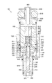
- FIG. 1 is a cross-sectional view showing the configuration of the fuel injection valve according to the first embodiment.
- FIG. 2 is a cross-sectional view showing the configuration of the needle according to the first embodiment.
- FIG. 3 is a cross-sectional view showing the configuration of the fuel injection valve according to the first embodiment.
- FIG. 4 is a cross-sectional view showing the configuration of the fuel injection valve according to the first embodiment.
- FIG. 5 is a cross-sectional view showing the configuration of the fuel injection valve according to the first embodiment.
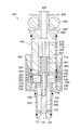
- FIG. 6 is a cross-sectional view showing the configuration of the fuel injection valve according to the second embodiment.
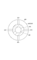
- FIG. 7 is a cross-sectional view showing the configuration of the movable core according to the second embodiment.
- FIG. 8 is a cross-sectional view showing the configuration of the fuel injection valve according to the third embodiment.
- FIG. 9 is a cross-sectional view showing the configuration of the needle according to the third embodiment.
- FIG. 10 is a cross-sectional view showing a configuration of a needle according to a modification of the third embodiment.
- the configuration of the fuel injection valve 10 according to the first embodiment will be described with reference to FIG.
- the fuel injection valve 10 is provided in an internal combustion engine (not shown), and is a device for injecting and supplying fuel to the internal combustion engine.
- gaseous fuel is used as the above-described fuel.
- the fuel injection valve 10 includes a housing 100, a needle 200, a fixed core 400, a movable core 300, and a coil 500.
- the housing 100 is a member that is formed as a generally cylindrical container in its entirety. In FIG. 1, a state in which the housing 100 is vertically aligned in the longitudinal direction is illustrated. In the following, for convenience of the description, words such as “upper side” may be simply used to indicate the upper side in FIG. Moreover, the word “lower side” etc. may be used only as what shows the lower side in FIG.
- the fuel injection valve 10 when the fuel injection valve 10 is attached to the internal combustion engine, the fuel injection valve 10 may be directed in a direction different from the direction shown in FIG. 1.
- the fuel injection valve 10 may be attached to the internal combustion engine in a state where the injection hole 141 described later does not face vertically downward as shown in FIG. 1 but faces obliquely downward.
- the fuel injected from the fuel injection valve 10 flows from the upper side to the lower side inside the housing 100.
- the needle 200, the movable core 300, and the fixed core 400, which will be described later, are accommodated in any of the housings 100.
- the housing 100 has a first cylindrical member 110, a second cylindrical member 120, a third cylindrical member 130, and an injection nozzle 140. Each of these is formed as a substantially cylindrical member, and is disposed in a state in which the central axes of the members coincide with each other.
- the first tubular member 110 is disposed at the most upstream side of the housing 100 along the fuel flow direction.
- the first tubular member 110 is formed of ferritic stainless steel which is a magnetic material.
- a connection member 800 described later is connected to the upper end portion of the first tubular member 110. The fuel supplied to the fuel injection valve 10 from the outside flows into the inside of the first cylindrical member 110 through the connection member 800.
- the second tubular member 120 is disposed at a position on the downstream side of the first tubular member 110 along the fuel flow direction in the housing 100.
- the second cylindrical member 120 is formed of austenitic stainless steel which is a nonmagnetic material.
- the inner diameter of the second tubular member 120 is equal to the inner diameter of the first tubular member 110.
- the upper end of the second cylindrical member 120 is fixed to the lower end of the first cylindrical member 110 by welding.
- the third cylindrical member 130 is disposed at a position on the downstream side of the second cylindrical member 120 along the fuel flow direction in the housing 100.
- the third cylindrical member 130 is formed of ferritic stainless steel which is a magnetic material.
- the inner diameter of the upper side portion of the third cylindrical member 130 is equal to the inner diameter of the second cylindrical member 120.
- the upper end of the third cylindrical member 130 is fixed to the lower end of the second cylindrical member 120 by welding.
- the inner diameter of the lower side portion of the third tubular member 130 is smaller than the inner diameter of the second tubular member 120 than the portion denoted by reference numeral 131.
- symbol 131 is attached is also described below also as the "diameter reduction part 131.”
- the injection nozzle 140 is disposed in the housing 100 at the most downstream position along the fuel flow direction.
- the injection nozzle 140 is fixed to the third cylindrical member 130 by welding in a state where the injection nozzle 140 is inserted into the inside of the third cylindrical member 130.
- An injection hole 141 is formed in the injection nozzle 140.
- the injection hole 141 is formed to penetrate the center of the injection nozzle 140 in the vertical direction.
- the injection hole 141 is a hole provided as an outlet of the fuel injected from the fuel injection valve 10.
- a valve seat 142 is formed on a portion of the upper side portion of the injection nozzle 140 which is an edge of the injection hole 141.
- the valve seat 142 is an inclined surface which descends inward.
- the valve seat 142 is a portion with which a seal portion 211 (described later) of the needle 200 abuts in order to close the injection hole 141 from the inside.
- the needle 200 is a substantially cylindrical member disposed inside the housing 100.
- the needle 200 is disposed so as to be movable along the longitudinal direction (vertical direction in FIG. 1) of the housing 100 in a state in which the central axis of the needle 200 is moved to the central axis of the housing 100.
- the needle 200 is formed of martensitic stainless steel.
- a seal portion 211 is formed at an end of the needle 200 on the injection nozzle 140 side.
- FIG. 1 shows the valve closing state of the fuel injection valve 10.
- the needle 200 moves upward and the seal portion 211 separates from the valve seat 142, the injection hole 141 is opened. Thereby, the injection of the fuel from the injection hole 141 is performed.
- the needle 200 is provided as a member for switching the opening and closing of the injection hole 141 by moving up and down inside the housing 100.
- the needle 200 has a cylindrical portion 210 and a flange 220.
- the cylindrical portion 210 is a cylindrical portion extending up and down, and occupies most of the needle 200.
- the seal portion 211 described above is formed at the lower end of the cylindrical portion 210.
- the flange 220 is a disk-shaped portion formed to project from the upper end of the cylindrical portion 210 to the periphery (side).
- An internal flow passage 230 is formed inside the cylindrical portion 210.
- the internal flow passage 230 is a space formed as part of a flow passage for fuel to pass through.
- the internal flow passage 230 is formed as an elongated space along the longitudinal direction of the needle 200, and the upper end thereof is open at the upper surface 221 of the flange 220.
- a plurality of openings 240 connecting the inner side (that is, the inner flow passage 230) of the cylindrical portion 210 and the outer side are formed on the side surface of the cylindrical portion 210.
- Each opening 240 is formed at a position near the lower end of the internal flow passage 230.
- the space formed between the outer surface of the cylindrical portion 210 and the inner surface of the third cylindrical member 130 is hereinafter also referred to as "space SP2".
- the opening 240 allows the internal flow passage 230 and the space SP2 to communicate with each other.
- a plurality of openings 250 connecting the inner side (that is, the internal flow path 230) of the cylindrical portion 210 and the outer side are further formed on the side surface of the cylindrical portion 210.
- Each opening 250 is formed at a position slightly below the flange 220 in the internal flow passage 230.
- the opening 250 can be referred to as a through hole formed to penetrate a portion of the needle 200.
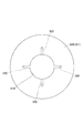
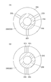
- FIG. 2 is a cross-sectional view showing a state in which the needle 200 is cut up and down at the position of the opening 250 and the cross section is viewed from the lower side.
- four openings 250 are formed in this embodiment. Further, the openings 250 are formed at equal intervals along the circumferential direction of the cylindrical portion 210. The effect of the formation of the opening 250 will be described later.
- the fixed core 400 is a cylindrical member fixed to the inside of the housing 100.
- the fixed core 400 is formed of ferritic stainless steel which is a magnetic material.
- the fixed core 400 is disposed so as to straddle both of the first cylindrical member 110 and the second cylindrical member 120, and is fixed to the respective inner surfaces.
- a space SP1 is formed so as to penetrate the fixed core 400 up and down.
- the space SP1 is a part of the flow path through which the fuel passes.
- the inner diameter of the fixed core 400 is slightly larger than the outer diameter of the flange 220 that the needle 200 has. As shown in FIG. 1, a part of the flange 220 is inserted into the space SP1 from the lower side.
- An adjustment member 600 is disposed at a position to be an upper side portion of the space SP1.
- the adjusting member 600 is a cylindrical member and is press-fitted and fixed to the inside of the fixed core 400.
- a through hole 610 is formed on the inside of the adjusting member 600 so as to penetrate the adjusting member 600 in the vertical direction.
- the through hole 610 is a part of the flow path through which the fuel passes.
- a spring 710 is disposed between the lower surface 601 of the adjustment member 600 and the upper surface 221 of the flange 220 in the space SP1.
- the spring 710 biases the needle 200 downward (ie, toward the valve seat 142).
- the magnitude of the biasing force of the spring 710 is adjusted by the height of the adjusting member 600.
- the movable core 300 is a cylindrical member disposed at a position below the fixed core 400.
- the movable core 300 is formed of ferritic stainless steel which is a magnetic material.
- the movable core 300 is disposed so as to be movable along the longitudinal direction (vertical direction in FIG. 1) of the housing 100 with the central axis of the movable core 300 moved to the central axis of the housing 100.
- the upper surface 301 of the movable core 300 is opposed to the lower surface 401 of the fixed core.
- the movable core 300 is provided as a member that moves up and down with the needle 200.
- the needle 200 and the movable core 300 are not integral members, and both are separated from each other. That is, the movable core 300 can move up and down relative to the needle 200.
- a through hole 310 is formed inside the movable core 300 so as to penetrate the movable core 300 in the vertical direction.
- the inner diameter of the through hole 310 is slightly larger than the outer diameter of the cylindrical portion 210 of the needle 200.
- a cylindrical portion 210 is inserted inside the through hole 310.
- the portion where the inner surface of the through hole 310 and the outer surface of the cylindrical portion 210 are facing is a portion where sliding occurs between the two when the fuel injection valve 10 performs the opening / closing operation, as will be described later. . Therefore, the portion (that is, the portion where the sliding occurs between the movable core 300 and the needle 200) is hereinafter also referred to as "sliding portion FR".
- the sliding portion FR the movable core 300 and the cylindrical portion 210 are not in close contact with each other as a whole, and a slight gap to the extent that fuel can pass is formed between the two.
- a spring 720 is disposed between the lower surface 302 of the movable core 300 and the reduced diameter portion 131 of the third cylindrical member 130.
- the spring 720 biases the movable core 300 upward (that is, opposite to the valve seat 142).
- the upper surface 301 of the movable core 300 is pressed against the lower surface 222 of the flange 220.
- the magnitude of the biasing force of the spring 720 is smaller than the magnitude of the biasing force of the spring 710. For this reason, in the state where current is not supplied to the coil 500 described later, the seal portion 211 of the needle 200 is in a state of being in contact with the valve seat 142 and pressed.
- the coil 500 generates a magnetic attraction between the fixed core 400 and the movable core 300.
- the coil 500 is disposed to surround the outside of the first tubular member 110, the second tubular member 120, and the third tubular member 130.
- the outer side of the coil 500 is surrounded by a holder 150.
- the holder 150 is a substantially cylindrical member, and is formed of ferritic stainless steel as a magnetic material.
- the holder 150 is fixed by welding to a portion of the third cylindrical member 130 which is on the lower side than the reduced diameter portion 131.
- the space around the coil 500, that is, the space between the holder 150 and the housing 100 is molded by the resin 160.
- a connecting member 800 is attached to the upper portion of the housing 100, that is, the upper portion of the first tubular member 110.
- the connecting member 800 is a portion connected to a delivery pipe (not shown) for distributing fuel to each cylinder.
- the connecting member 800 is formed with a through hole 801 penetrating the connecting member 800 in the vertical direction.
- the through hole 801 is a flow path through which the fuel supplied to the fuel injection valve 10 passes.
- the connection member 800 is fixed to the first cylindrical member 110 by welding in a state where the vicinity of the lower end portion of the connection member 800 is inserted into the inside of the first cylindrical member 110.
- the connecting member 800 is provided with an O-ring 810.
- the O-ring 810 is a seal member for preventing the fuel supplied from the delivery pipe to the fuel injection valve 10 from leaking out.
- a force is applied to the O-ring 810 due to the pressure of the fuel inside the delivery pipe. This force causes the O-ring 810 to be deformed, and a part thereof may be fitted between the connection member 800 and the delivery pipe. In order to prevent this, a backup ring 820 is provided below the O-ring 810.
- the reference numeral 830 in FIG. 1 is a ring-shaped member for preventing the O-ring 810 from coming upward.
- the movable core 300 starts moving upward by the magnetic attraction force.
- the needle 200 since the flange 220 of the needle 200 is in contact with the upper surface 301 of the movable core 300, the needle 200 also starts to move upward simultaneously. That is, the movable core 300 and the needle 200 start moving integrally upward.
- FIG. 3 What is shown in FIG. 3 is the state of the fuel injection valve 10 at the moment when the upper surface 301 of the movable core 300 moved upward as described above abuts on the lower surface 401 of the fixed core 400.
- a flow of fuel is generated inside the fuel injection valve 10.
- the fuel passes through the through hole 801, the through hole 610, the space SP1, and the internal flow passage 230 in order, and then flows into the space SP2 through the opening 240. Thereafter, fuel is injected from the injection holes 141 to the outside.
- Part of the fuel that has flowed into the internal flow passage 230 from the space SP1 is also supplied near the upper end of the sliding portion FR through the opening 250.
- the fuel flows downward through the sliding portion FR and then joins the fuel in the space SP2.
- the opening 250 in this embodiment functions as a "supply unit" for supplying fuel to the sliding unit FR.
- the flow of the fuel in the sliding portion FR as described above is generated due to the pressure difference of the fuel between the space SP1 and the space SP2.
- FIG. 4 shows the state after the needle 200 has moved further upward. Also in the state of FIG. 4, the same fuel flow as that indicated by the arrow in FIG. 3 is generated.
- FIG. 5 shows the state after the movable core 300 has moved further downward.
- the movable core 300 moved downward is moved upward again by the biasing force of the spring 720. Finally, the upper surface 301 of the movable core 300 is in contact with the lower surface 222 of the flange 220, that is, the condition shown in FIG.
- the occurrence of sliding between the movable core 300 and the needle 200 may generate new abrasion powder at the sliding portion FR.
- the wear powder is discharged from the sliding portion FR by the fuel flow as described above when the next valve opening is started.
- both the needle 200 and the movable core 300 move upward while the wear powder generated by the sliding at the time of valve closing remains in the sliding portion FR. Thereafter, due to sliding in the process of transitioning from the state of FIG. 3 to the state of FIG. In this case, since a wear powder of an amount corresponding to two slidings is deposited on the sliding portion FR, the possibility of problems such as aggregation increases. Furthermore, since the next sliding occurs in a state where a large amount of wear powder is present in the sliding portion FR, the possibility of accelerated wear in the sliding portion FR also increases.
- the second embodiment will be described with reference to FIGS. 6 and 7. In the following, differences from the first embodiment will be mainly described, and descriptions of points in common with the first embodiment will be omitted as appropriate.
- the needle 200 is not formed with the opening 250 as a supply portion, and instead, a through hole 320 is formed in the movable core 300.
- the through hole 320 is formed as a hole which obliquely penetrates from the upper surface 301 of the movable core 300 to the inner wall surface of the through hole 310.
- the position where the through hole 320 is open on the upper surface 301 is a position slightly outside the portion where the flange 220 abuts.
- FIG. 7 is a view of the movable core 300 as viewed from above. As shown in the figure, in the present embodiment, four through holes 320 are formed. In addition, the through holes 320 are formed at equal intervals along the circumferential direction of the cylindrical portion 210.
- each through hole 320 functions as a "supply unit" in the present embodiment. Even in a mode in which the supply portion is formed as the through hole 320 formed to penetrate a part of the movable core 300 as in the present embodiment, the same effects as those described in the first embodiment can be obtained. Play.
- the third embodiment will be described with reference to FIGS. 8 and 9. In the following, differences from the first embodiment will be mainly described, and descriptions of points in common with the first embodiment will be omitted as appropriate.
- the needle 200 is not formed with the opening 250 as a supply portion, and instead, a groove 223 is formed in the flange 220 of the needle 200.
- the groove 223 is formed at a portion where the movable core 300 and the flange 220 abut.
- the groove 223 is a linear groove formed in the lower surface 222 of the flange 220 so as to extend outward in the radial direction from the boundary with the cylindrical portion 210.
- the groove 223 extends to a position to be an outer peripheral end of the lower surface 222. Thereby, the space SP1 and the sliding portion FR are communicated by the groove 223.
- FIG. 9 is a cross-sectional view showing a state in which the needle 200 is cut up and down at a position in the middle of the cylindrical portion 210 and the cross section is viewed from the lower side. As shown in the figure, in the present embodiment, four grooves 223 are formed. Further, the grooves 223 are formed at equal intervals along the circumferential direction of the cylindrical portion 210.
- each groove 223 functions as a "supply unit" in the present embodiment. Even in the aspect in which the supply portion is formed as the groove 223 of the flange 220 as in the present embodiment, the same effects as those described in the first embodiment can be obtained.
- the fuel from the supply unit is supplied throughout the entire area including the vicinity of the upper end portion of the sliding portion FR, so the abrasion powder can be more reliably discharged from the sliding portion FR.
- the groove 223 for communicating the space SP1 with the sliding portion FR may be formed on the lower surface 222 of the flange 220 as described above, but a similar groove is formed on the upper surface 301 of the movable core 300. It may be done.
- grooves may be formed in both the lower surface 222 of the flange 220 and the upper surface 301 of the movable core 300 to communicate the space SP1 with the sliding portion FR.
- a groove functioning as a supply portion may be formed in the portion where the movable core 300 and the flange 220 abut.
- the needle 200 receives a force from the fuel in the groove 223.
- the direction of this force is the direction from the groove 223 toward the central axis of the cylindrical portion 210, respectively.
- the arrangement of the grooves 223 for balancing the force that the needle 200 receives from the fuel of each groove 223 is not limited to the arrangement as shown in FIG.
- three grooves 223 instead of four may be equally spaced.
- the grooves 223 are arranged so as to be symmetrical in the left-right direction in the drawing. Even with the arrangement of the grooves 223, the force received by the needle 200 from the fuel of each groove 223 (supply part) can be balanced.
- the arrangement of the supply units as described above can also be applied to the first embodiment and the second embodiment described above.
- the supply unit may be provided to both the movable core 300 and the needle 200.
- the opening 250 shown in FIG. 1 and the through hole 320 shown in FIG. 6 are provided.
Landscapes
- Engineering & Computer Science (AREA)
- Chemical & Material Sciences (AREA)
- Combustion & Propulsion (AREA)
- Mechanical Engineering (AREA)
- General Engineering & Computer Science (AREA)
- Physics & Mathematics (AREA)
- Electromagnetism (AREA)
- Chemical Kinetics & Catalysis (AREA)
- General Chemical & Material Sciences (AREA)
- Oil, Petroleum & Natural Gas (AREA)
- Fuel-Injection Apparatus (AREA)
Priority Applications (1)
| Application Number | Priority Date | Filing Date | Title |
|---|---|---|---|
| DE112018003718.5T DE112018003718T5 (de) | 2017-07-19 | 2018-06-05 | Kraftstoffeinspritzventil |
Applications Claiming Priority (2)
| Application Number | Priority Date | Filing Date | Title |
|---|---|---|---|
| JP2017140092A JP2019019780A (ja) | 2017-07-19 | 2017-07-19 | 燃料噴射弁 |
| JP2017-140092 | 2017-07-19 |
Publications (1)
| Publication Number | Publication Date |
|---|---|
| WO2019017097A1 true WO2019017097A1 (ja) | 2019-01-24 |
Family
ID=65015223
Family Applications (1)
| Application Number | Title | Priority Date | Filing Date |
|---|---|---|---|
| PCT/JP2018/021489 Ceased WO2019017097A1 (ja) | 2017-07-19 | 2018-06-05 | 燃料噴射弁 |
Country Status (3)
| Country | Link |
|---|---|
| JP (1) | JP2019019780A (enExample) |
| DE (1) | DE112018003718T5 (enExample) |
| WO (1) | WO2019017097A1 (enExample) |
Families Citing this family (1)
| Publication number | Priority date | Publication date | Assignee | Title |
|---|---|---|---|---|
| JP7068721B1 (ja) * | 2020-11-11 | 2022-05-17 | 株式会社アンクレス | 情報提供装置、情報提供方法、及びプログラム |
Citations (6)
| Publication number | Priority date | Publication date | Assignee | Title |
|---|---|---|---|---|
| JPH09273451A (ja) * | 1996-04-05 | 1997-10-21 | Keehin:Kk | 気体燃料噴射弁 |
| JP2011163242A (ja) * | 2010-02-11 | 2011-08-25 | Denso Corp | 燃料噴射弁 |
| JP2013100756A (ja) * | 2011-11-08 | 2013-05-23 | Denso Corp | 燃料噴射弁 |
| JP2014080964A (ja) * | 2012-09-26 | 2014-05-08 | Denso Corp | 燃料噴射弁 |
| JP2015218664A (ja) * | 2014-05-19 | 2015-12-07 | 株式会社デンソー | 燃料噴射弁 |
| JP2016065539A (ja) * | 2014-09-17 | 2016-04-28 | 株式会社デンソー | 燃料噴射弁 |
Family Cites Families (1)
| Publication number | Priority date | Publication date | Assignee | Title |
|---|---|---|---|---|
| JP5445429B2 (ja) * | 2010-11-12 | 2014-03-19 | 株式会社デンソー | 燃料噴射装置 |
-
2017
- 2017-07-19 JP JP2017140092A patent/JP2019019780A/ja active Pending
-
2018
- 2018-06-05 WO PCT/JP2018/021489 patent/WO2019017097A1/ja not_active Ceased
- 2018-06-05 DE DE112018003718.5T patent/DE112018003718T5/de not_active Ceased
Patent Citations (6)
| Publication number | Priority date | Publication date | Assignee | Title |
|---|---|---|---|---|
| JPH09273451A (ja) * | 1996-04-05 | 1997-10-21 | Keehin:Kk | 気体燃料噴射弁 |
| JP2011163242A (ja) * | 2010-02-11 | 2011-08-25 | Denso Corp | 燃料噴射弁 |
| JP2013100756A (ja) * | 2011-11-08 | 2013-05-23 | Denso Corp | 燃料噴射弁 |
| JP2014080964A (ja) * | 2012-09-26 | 2014-05-08 | Denso Corp | 燃料噴射弁 |
| JP2015218664A (ja) * | 2014-05-19 | 2015-12-07 | 株式会社デンソー | 燃料噴射弁 |
| JP2016065539A (ja) * | 2014-09-17 | 2016-04-28 | 株式会社デンソー | 燃料噴射弁 |
Also Published As
| Publication number | Publication date |
|---|---|
| JP2019019780A (ja) | 2019-02-07 |
| DE112018003718T5 (de) | 2020-04-02 |
Similar Documents
| Publication | Publication Date | Title |
|---|---|---|
| JP6021785B2 (ja) | 燃料噴射弁 | |
| JP6836955B2 (ja) | 燃料噴射弁 | |
| JP2017532502A (ja) | 燃焼機関のための燃料噴射バルブ | |
| US10260640B2 (en) | Valve apparatus | |
| JP7323445B2 (ja) | 燃料噴射弁 | |
| WO2019017097A1 (ja) | 燃料噴射弁 | |
| KR102200623B1 (ko) | 유체 분사기 및 유체 분사기용 니들 | |
| CN110337538B (zh) | 燃料喷射阀 | |
| JP6544416B2 (ja) | 燃料噴射弁 | |
| JP6733701B2 (ja) | インジェクタ | |
| KR102104189B1 (ko) | 밸브 조립체 및 유체 분사 밸브 | |
| JP7352384B2 (ja) | 燃料噴射弁 | |
| JP7152274B2 (ja) | 燃料噴射装置 | |
| US11168656B2 (en) | Fuel injection valve and method for manufacturing fuel injection valve | |
| WO2017122421A1 (ja) | 燃料噴射装置 | |
| KR20160090762A (ko) | 연료 분사 밸브 | |
| EP3156638B1 (en) | Fuel injector | |
| JP6760422B2 (ja) | インジェクタ | |
| JP7311315B2 (ja) | 燃料噴射弁 | |
| JP7116609B2 (ja) | 燃料噴射弁 | |
| JP6945078B2 (ja) | 燃料噴射弁 | |
| KR102477720B1 (ko) | 유체 계량용 밸브 | |
| JP7063741B2 (ja) | 燃料噴射弁 | |
| JP2006214394A (ja) | 燃料噴射弁 | |
| CN100564863C (zh) | 气体喷射器 |
Legal Events
| Date | Code | Title | Description |
|---|---|---|---|
| 121 | Ep: the epo has been informed by wipo that ep was designated in this application |
Ref document number: 18835009 Country of ref document: EP Kind code of ref document: A1 |
|
| 122 | Ep: pct application non-entry in european phase |
Ref document number: 18835009 Country of ref document: EP Kind code of ref document: A1 |