WO2019017097A1 - 燃料噴射弁 - Google Patents
燃料噴射弁 Download PDFInfo
- Publication number
- WO2019017097A1 WO2019017097A1 PCT/JP2018/021489 JP2018021489W WO2019017097A1 WO 2019017097 A1 WO2019017097 A1 WO 2019017097A1 JP 2018021489 W JP2018021489 W JP 2018021489W WO 2019017097 A1 WO2019017097 A1 WO 2019017097A1
- Authority
- WO
- WIPO (PCT)
- Prior art keywords
- needle
- fuel
- movable core
- injection valve
- fuel injection
- Prior art date
Links
Images


Classifications
-
- F—MECHANICAL ENGINEERING; LIGHTING; HEATING; WEAPONS; BLASTING
- F02—COMBUSTION ENGINES; HOT-GAS OR COMBUSTION-PRODUCT ENGINE PLANTS
- F02M—SUPPLYING COMBUSTION ENGINES IN GENERAL WITH COMBUSTIBLE MIXTURES OR CONSTITUENTS THEREOF
- F02M51/00—Fuel-injection apparatus characterised by being operated electrically
- F02M51/06—Injectors peculiar thereto with means directly operating the valve needle
- F02M51/061—Injectors peculiar thereto with means directly operating the valve needle using electromagnetic operating means
- F02M51/0625—Injectors peculiar thereto with means directly operating the valve needle using electromagnetic operating means characterised by arrangement of mobile armatures
- F02M51/0664—Injectors peculiar thereto with means directly operating the valve needle using electromagnetic operating means characterised by arrangement of mobile armatures having a cylindrically or partly cylindrically shaped armature, e.g. entering the winding; having a plate-shaped or undulated armature entering the winding
- F02M51/0685—Injectors peculiar thereto with means directly operating the valve needle using electromagnetic operating means characterised by arrangement of mobile armatures having a cylindrically or partly cylindrically shaped armature, e.g. entering the winding; having a plate-shaped or undulated armature entering the winding the armature and the valve being allowed to move relatively to each other or not being attached to each other
-
- F—MECHANICAL ENGINEERING; LIGHTING; HEATING; WEAPONS; BLASTING
- F02—COMBUSTION ENGINES; HOT-GAS OR COMBUSTION-PRODUCT ENGINE PLANTS
- F02M—SUPPLYING COMBUSTION ENGINES IN GENERAL WITH COMBUSTIBLE MIXTURES OR CONSTITUENTS THEREOF
- F02M21/00—Apparatus for supplying engines with non-liquid fuels, e.g. gaseous fuels stored in liquid form
- F02M21/02—Apparatus for supplying engines with non-liquid fuels, e.g. gaseous fuels stored in liquid form for gaseous fuels
-
- F—MECHANICAL ENGINEERING; LIGHTING; HEATING; WEAPONS; BLASTING
- F02—COMBUSTION ENGINES; HOT-GAS OR COMBUSTION-PRODUCT ENGINE PLANTS
- F02M—SUPPLYING COMBUSTION ENGINES IN GENERAL WITH COMBUSTIBLE MIXTURES OR CONSTITUENTS THEREOF
- F02M51/00—Fuel-injection apparatus characterised by being operated electrically
- F02M51/06—Injectors peculiar thereto with means directly operating the valve needle
- F02M51/061—Injectors peculiar thereto with means directly operating the valve needle using electromagnetic operating means
- F02M51/0625—Injectors peculiar thereto with means directly operating the valve needle using electromagnetic operating means characterised by arrangement of mobile armatures
- F02M51/0664—Injectors peculiar thereto with means directly operating the valve needle using electromagnetic operating means characterised by arrangement of mobile armatures having a cylindrically or partly cylindrically shaped armature, e.g. entering the winding; having a plate-shaped or undulated armature entering the winding
- F02M51/0671—Injectors peculiar thereto with means directly operating the valve needle using electromagnetic operating means characterised by arrangement of mobile armatures having a cylindrically or partly cylindrically shaped armature, e.g. entering the winding; having a plate-shaped or undulated armature entering the winding the armature having an elongated valve body attached thereto
- F02M51/0682—Injectors peculiar thereto with means directly operating the valve needle using electromagnetic operating means characterised by arrangement of mobile armatures having a cylindrically or partly cylindrically shaped armature, e.g. entering the winding; having a plate-shaped or undulated armature entering the winding the armature having an elongated valve body attached thereto the body being hollow and its interior communicating with the fuel flow
-
- F—MECHANICAL ENGINEERING; LIGHTING; HEATING; WEAPONS; BLASTING
- F02—COMBUSTION ENGINES; HOT-GAS OR COMBUSTION-PRODUCT ENGINE PLANTS
- F02M—SUPPLYING COMBUSTION ENGINES IN GENERAL WITH COMBUSTIBLE MIXTURES OR CONSTITUENTS THEREOF
- F02M2200/00—Details of fuel-injection apparatus, not otherwise provided for
- F02M2200/80—Fuel injection apparatus manufacture, repair or assembly
- F02M2200/8084—Fuel injection apparatus manufacture, repair or assembly involving welding or soldering
Definitions
- the present disclosure relates to a fuel injection valve.
- a fuel injection valve provided in an internal combustion engine one having a configuration in which the opening and closing of an injection hole, which is an outlet of fuel, is switched by operating an inner movable core with a needle by magnetic attraction is known.
- the movable core and the needle are configured as an integral member.
- the coil When the coil is energized, the movable core and the needle are operated by the generated magnetic attraction force, whereby the opening and closing of the injection hole are switched.
- Patent Document 1 also describes a structure capable of scraping off foreign matter that has entered and adhered to the inside of a fuel injection valve together with fuel by the operation of a needle. According to the said structure, the malfunctioning of the fuel injection valve accompanying the biting of a foreign material can be prevented.
- the movable core and the needle are configured as an integral member.
- the movable core and the needle are also configured to be separated from each other. In the configuration in which the two are separated, the impact force when the movable core collides with the fixed core is alleviated, so the durability of the fuel injection valve can be improved.
- the movable core moves relative to the needle each time the injection hole is opened and closed, and sliding occurs between the two, though for a short period of time. I will. If the wear powder generated by the sliding remains on the sliding portion, the movement of the movable core and the needle may be affected by the aggregation of the wear powder and the like. In addition, when the movable core moves relative to the needle again with the wear powder remaining on the sliding portion, the wear on the sliding portion is promoted, and more wear powder is generated. . In order to prevent such a phenomenon, it is preferable to discharge generated wear powder from the sliding portion as quickly as possible.
- An object of the present disclosure is to provide a fuel injection valve capable of quickly discharging wear powder generated between a movable core and a needle.
- the fuel injection valve includes a housing having a nozzle hole for injecting fuel, a needle for switching the opening and closing of the nozzle hole by moving inside the housing, and a needle receiving magnetic attraction force.
- a movable core that moves and a coil that generates a magnetic attraction force are provided.
- the needle and the movable core are separated from one another.
- the movable core and the needle are configured such that when the movable core and the needle move together, a flow of fuel occurs when the portion where the sliding occurs between the movable core and the needle is the sliding portion.
- the supply part for supplying a fuel to a sliding part is formed in at least one of these.
- the fuel injection valve having such a configuration the fuel is supplied from the supply portion to the sliding portion, so that the flow of fuel occurs in the sliding portion. If wear powder is generated at the sliding portion, the wear powder is discharged from the sliding portion by the flow of the fuel. The wear powder is discharged from the sliding portion each time fuel injection is performed, so the wear powder does not continue to remain in the sliding portion for a long period of time.
- a fuel injection valve capable of rapidly discharging wear powder generated between the movable core and the needle.
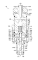
- FIG. 1 is a cross-sectional view showing the configuration of the fuel injection valve according to the first embodiment.
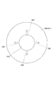
- FIG. 2 is a cross-sectional view showing the configuration of the needle according to the first embodiment.
- FIG. 3 is a cross-sectional view showing the configuration of the fuel injection valve according to the first embodiment.
- FIG. 4 is a cross-sectional view showing the configuration of the fuel injection valve according to the first embodiment.
- FIG. 5 is a cross-sectional view showing the configuration of the fuel injection valve according to the first embodiment.
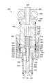
- FIG. 6 is a cross-sectional view showing the configuration of the fuel injection valve according to the second embodiment.
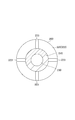
- FIG. 7 is a cross-sectional view showing the configuration of the movable core according to the second embodiment.
- FIG. 8 is a cross-sectional view showing the configuration of the fuel injection valve according to the third embodiment.
- FIG. 9 is a cross-sectional view showing the configuration of the needle according to the third embodiment.
- FIG. 10 is a cross-sectional view showing a configuration of a needle according to a modification of the third embodiment.
- the configuration of the fuel injection valve 10 according to the first embodiment will be described with reference to FIG.
- the fuel injection valve 10 is provided in an internal combustion engine (not shown), and is a device for injecting and supplying fuel to the internal combustion engine.
- gaseous fuel is used as the above-described fuel.
- the fuel injection valve 10 includes a housing 100, a needle 200, a fixed core 400, a movable core 300, and a coil 500.
- the housing 100 is a member that is formed as a generally cylindrical container in its entirety. In FIG. 1, a state in which the housing 100 is vertically aligned in the longitudinal direction is illustrated. In the following, for convenience of the description, words such as “upper side” may be simply used to indicate the upper side in FIG. Moreover, the word “lower side” etc. may be used only as what shows the lower side in FIG.
- the fuel injection valve 10 when the fuel injection valve 10 is attached to the internal combustion engine, the fuel injection valve 10 may be directed in a direction different from the direction shown in FIG. 1.
- the fuel injection valve 10 may be attached to the internal combustion engine in a state where the injection hole 141 described later does not face vertically downward as shown in FIG. 1 but faces obliquely downward.
- the fuel injected from the fuel injection valve 10 flows from the upper side to the lower side inside the housing 100.
- the needle 200, the movable core 300, and the fixed core 400, which will be described later, are accommodated in any of the housings 100.
- the housing 100 has a first cylindrical member 110, a second cylindrical member 120, a third cylindrical member 130, and an injection nozzle 140. Each of these is formed as a substantially cylindrical member, and is disposed in a state in which the central axes of the members coincide with each other.
- the first tubular member 110 is disposed at the most upstream side of the housing 100 along the fuel flow direction.
- the first tubular member 110 is formed of ferritic stainless steel which is a magnetic material.
- a connection member 800 described later is connected to the upper end portion of the first tubular member 110. The fuel supplied to the fuel injection valve 10 from the outside flows into the inside of the first cylindrical member 110 through the connection member 800.
- the second tubular member 120 is disposed at a position on the downstream side of the first tubular member 110 along the fuel flow direction in the housing 100.
- the second cylindrical member 120 is formed of austenitic stainless steel which is a nonmagnetic material.
- the inner diameter of the second tubular member 120 is equal to the inner diameter of the first tubular member 110.
- the upper end of the second cylindrical member 120 is fixed to the lower end of the first cylindrical member 110 by welding.
- the third cylindrical member 130 is disposed at a position on the downstream side of the second cylindrical member 120 along the fuel flow direction in the housing 100.
- the third cylindrical member 130 is formed of ferritic stainless steel which is a magnetic material.
- the inner diameter of the upper side portion of the third cylindrical member 130 is equal to the inner diameter of the second cylindrical member 120.
- the upper end of the third cylindrical member 130 is fixed to the lower end of the second cylindrical member 120 by welding.
- the inner diameter of the lower side portion of the third tubular member 130 is smaller than the inner diameter of the second tubular member 120 than the portion denoted by reference numeral 131.
- symbol 131 is attached is also described below also as the "diameter reduction part 131.”
- the injection nozzle 140 is disposed in the housing 100 at the most downstream position along the fuel flow direction.
- the injection nozzle 140 is fixed to the third cylindrical member 130 by welding in a state where the injection nozzle 140 is inserted into the inside of the third cylindrical member 130.
- An injection hole 141 is formed in the injection nozzle 140.
- the injection hole 141 is formed to penetrate the center of the injection nozzle 140 in the vertical direction.
- the injection hole 141 is a hole provided as an outlet of the fuel injected from the fuel injection valve 10.
- a valve seat 142 is formed on a portion of the upper side portion of the injection nozzle 140 which is an edge of the injection hole 141.
- the valve seat 142 is an inclined surface which descends inward.
- the valve seat 142 is a portion with which a seal portion 211 (described later) of the needle 200 abuts in order to close the injection hole 141 from the inside.
- the needle 200 is a substantially cylindrical member disposed inside the housing 100.
- the needle 200 is disposed so as to be movable along the longitudinal direction (vertical direction in FIG. 1) of the housing 100 in a state in which the central axis of the needle 200 is moved to the central axis of the housing 100.
- the needle 200 is formed of martensitic stainless steel.
- a seal portion 211 is formed at an end of the needle 200 on the injection nozzle 140 side.
- FIG. 1 shows the valve closing state of the fuel injection valve 10.
- the needle 200 moves upward and the seal portion 211 separates from the valve seat 142, the injection hole 141 is opened. Thereby, the injection of the fuel from the injection hole 141 is performed.
- the needle 200 is provided as a member for switching the opening and closing of the injection hole 141 by moving up and down inside the housing 100.
- the needle 200 has a cylindrical portion 210 and a flange 220.
- the cylindrical portion 210 is a cylindrical portion extending up and down, and occupies most of the needle 200.
- the seal portion 211 described above is formed at the lower end of the cylindrical portion 210.
- the flange 220 is a disk-shaped portion formed to project from the upper end of the cylindrical portion 210 to the periphery (side).
- An internal flow passage 230 is formed inside the cylindrical portion 210.
- the internal flow passage 230 is a space formed as part of a flow passage for fuel to pass through.
- the internal flow passage 230 is formed as an elongated space along the longitudinal direction of the needle 200, and the upper end thereof is open at the upper surface 221 of the flange 220.
- a plurality of openings 240 connecting the inner side (that is, the inner flow passage 230) of the cylindrical portion 210 and the outer side are formed on the side surface of the cylindrical portion 210.
- Each opening 240 is formed at a position near the lower end of the internal flow passage 230.
- the space formed between the outer surface of the cylindrical portion 210 and the inner surface of the third cylindrical member 130 is hereinafter also referred to as "space SP2".
- the opening 240 allows the internal flow passage 230 and the space SP2 to communicate with each other.
- a plurality of openings 250 connecting the inner side (that is, the internal flow path 230) of the cylindrical portion 210 and the outer side are further formed on the side surface of the cylindrical portion 210.
- Each opening 250 is formed at a position slightly below the flange 220 in the internal flow passage 230.
- the opening 250 can be referred to as a through hole formed to penetrate a portion of the needle 200.
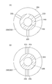
- FIG. 2 is a cross-sectional view showing a state in which the needle 200 is cut up and down at the position of the opening 250 and the cross section is viewed from the lower side.
- four openings 250 are formed in this embodiment. Further, the openings 250 are formed at equal intervals along the circumferential direction of the cylindrical portion 210. The effect of the formation of the opening 250 will be described later.
- the fixed core 400 is a cylindrical member fixed to the inside of the housing 100.
- the fixed core 400 is formed of ferritic stainless steel which is a magnetic material.
- the fixed core 400 is disposed so as to straddle both of the first cylindrical member 110 and the second cylindrical member 120, and is fixed to the respective inner surfaces.
- a space SP1 is formed so as to penetrate the fixed core 400 up and down.
- the space SP1 is a part of the flow path through which the fuel passes.
- the inner diameter of the fixed core 400 is slightly larger than the outer diameter of the flange 220 that the needle 200 has. As shown in FIG. 1, a part of the flange 220 is inserted into the space SP1 from the lower side.
- An adjustment member 600 is disposed at a position to be an upper side portion of the space SP1.
- the adjusting member 600 is a cylindrical member and is press-fitted and fixed to the inside of the fixed core 400.
- a through hole 610 is formed on the inside of the adjusting member 600 so as to penetrate the adjusting member 600 in the vertical direction.
- the through hole 610 is a part of the flow path through which the fuel passes.
- a spring 710 is disposed between the lower surface 601 of the adjustment member 600 and the upper surface 221 of the flange 220 in the space SP1.
- the spring 710 biases the needle 200 downward (ie, toward the valve seat 142).
- the magnitude of the biasing force of the spring 710 is adjusted by the height of the adjusting member 600.
- the movable core 300 is a cylindrical member disposed at a position below the fixed core 400.
- the movable core 300 is formed of ferritic stainless steel which is a magnetic material.
- the movable core 300 is disposed so as to be movable along the longitudinal direction (vertical direction in FIG. 1) of the housing 100 with the central axis of the movable core 300 moved to the central axis of the housing 100.
- the upper surface 301 of the movable core 300 is opposed to the lower surface 401 of the fixed core.
- the movable core 300 is provided as a member that moves up and down with the needle 200.
- the needle 200 and the movable core 300 are not integral members, and both are separated from each other. That is, the movable core 300 can move up and down relative to the needle 200.
- a through hole 310 is formed inside the movable core 300 so as to penetrate the movable core 300 in the vertical direction.
- the inner diameter of the through hole 310 is slightly larger than the outer diameter of the cylindrical portion 210 of the needle 200.
- a cylindrical portion 210 is inserted inside the through hole 310.
- the portion where the inner surface of the through hole 310 and the outer surface of the cylindrical portion 210 are facing is a portion where sliding occurs between the two when the fuel injection valve 10 performs the opening / closing operation, as will be described later. . Therefore, the portion (that is, the portion where the sliding occurs between the movable core 300 and the needle 200) is hereinafter also referred to as "sliding portion FR".
- the sliding portion FR the movable core 300 and the cylindrical portion 210 are not in close contact with each other as a whole, and a slight gap to the extent that fuel can pass is formed between the two.
- a spring 720 is disposed between the lower surface 302 of the movable core 300 and the reduced diameter portion 131 of the third cylindrical member 130.
- the spring 720 biases the movable core 300 upward (that is, opposite to the valve seat 142).
- the upper surface 301 of the movable core 300 is pressed against the lower surface 222 of the flange 220.
- the magnitude of the biasing force of the spring 720 is smaller than the magnitude of the biasing force of the spring 710. For this reason, in the state where current is not supplied to the coil 500 described later, the seal portion 211 of the needle 200 is in a state of being in contact with the valve seat 142 and pressed.
- the coil 500 generates a magnetic attraction between the fixed core 400 and the movable core 300.
- the coil 500 is disposed to surround the outside of the first tubular member 110, the second tubular member 120, and the third tubular member 130.
- the outer side of the coil 500 is surrounded by a holder 150.
- the holder 150 is a substantially cylindrical member, and is formed of ferritic stainless steel as a magnetic material.
- the holder 150 is fixed by welding to a portion of the third cylindrical member 130 which is on the lower side than the reduced diameter portion 131.
- the space around the coil 500, that is, the space between the holder 150 and the housing 100 is molded by the resin 160.
- a connecting member 800 is attached to the upper portion of the housing 100, that is, the upper portion of the first tubular member 110.
- the connecting member 800 is a portion connected to a delivery pipe (not shown) for distributing fuel to each cylinder.
- the connecting member 800 is formed with a through hole 801 penetrating the connecting member 800 in the vertical direction.
- the through hole 801 is a flow path through which the fuel supplied to the fuel injection valve 10 passes.
- the connection member 800 is fixed to the first cylindrical member 110 by welding in a state where the vicinity of the lower end portion of the connection member 800 is inserted into the inside of the first cylindrical member 110.
- the connecting member 800 is provided with an O-ring 810.
- the O-ring 810 is a seal member for preventing the fuel supplied from the delivery pipe to the fuel injection valve 10 from leaking out.
- a force is applied to the O-ring 810 due to the pressure of the fuel inside the delivery pipe. This force causes the O-ring 810 to be deformed, and a part thereof may be fitted between the connection member 800 and the delivery pipe. In order to prevent this, a backup ring 820 is provided below the O-ring 810.
- the reference numeral 830 in FIG. 1 is a ring-shaped member for preventing the O-ring 810 from coming upward.
- the movable core 300 starts moving upward by the magnetic attraction force.
- the needle 200 since the flange 220 of the needle 200 is in contact with the upper surface 301 of the movable core 300, the needle 200 also starts to move upward simultaneously. That is, the movable core 300 and the needle 200 start moving integrally upward.
- FIG. 3 What is shown in FIG. 3 is the state of the fuel injection valve 10 at the moment when the upper surface 301 of the movable core 300 moved upward as described above abuts on the lower surface 401 of the fixed core 400.
- a flow of fuel is generated inside the fuel injection valve 10.
- the fuel passes through the through hole 801, the through hole 610, the space SP1, and the internal flow passage 230 in order, and then flows into the space SP2 through the opening 240. Thereafter, fuel is injected from the injection holes 141 to the outside.
- Part of the fuel that has flowed into the internal flow passage 230 from the space SP1 is also supplied near the upper end of the sliding portion FR through the opening 250.
- the fuel flows downward through the sliding portion FR and then joins the fuel in the space SP2.
- the opening 250 in this embodiment functions as a "supply unit" for supplying fuel to the sliding unit FR.
- the flow of the fuel in the sliding portion FR as described above is generated due to the pressure difference of the fuel between the space SP1 and the space SP2.
- FIG. 4 shows the state after the needle 200 has moved further upward. Also in the state of FIG. 4, the same fuel flow as that indicated by the arrow in FIG. 3 is generated.
- FIG. 5 shows the state after the movable core 300 has moved further downward.
- the movable core 300 moved downward is moved upward again by the biasing force of the spring 720. Finally, the upper surface 301 of the movable core 300 is in contact with the lower surface 222 of the flange 220, that is, the condition shown in FIG.
- the occurrence of sliding between the movable core 300 and the needle 200 may generate new abrasion powder at the sliding portion FR.
- the wear powder is discharged from the sliding portion FR by the fuel flow as described above when the next valve opening is started.
- both the needle 200 and the movable core 300 move upward while the wear powder generated by the sliding at the time of valve closing remains in the sliding portion FR. Thereafter, due to sliding in the process of transitioning from the state of FIG. 3 to the state of FIG. In this case, since a wear powder of an amount corresponding to two slidings is deposited on the sliding portion FR, the possibility of problems such as aggregation increases. Furthermore, since the next sliding occurs in a state where a large amount of wear powder is present in the sliding portion FR, the possibility of accelerated wear in the sliding portion FR also increases.
- the second embodiment will be described with reference to FIGS. 6 and 7. In the following, differences from the first embodiment will be mainly described, and descriptions of points in common with the first embodiment will be omitted as appropriate.
- the needle 200 is not formed with the opening 250 as a supply portion, and instead, a through hole 320 is formed in the movable core 300.
- the through hole 320 is formed as a hole which obliquely penetrates from the upper surface 301 of the movable core 300 to the inner wall surface of the through hole 310.
- the position where the through hole 320 is open on the upper surface 301 is a position slightly outside the portion where the flange 220 abuts.
- FIG. 7 is a view of the movable core 300 as viewed from above. As shown in the figure, in the present embodiment, four through holes 320 are formed. In addition, the through holes 320 are formed at equal intervals along the circumferential direction of the cylindrical portion 210.
- each through hole 320 functions as a "supply unit" in the present embodiment. Even in a mode in which the supply portion is formed as the through hole 320 formed to penetrate a part of the movable core 300 as in the present embodiment, the same effects as those described in the first embodiment can be obtained. Play.
- the third embodiment will be described with reference to FIGS. 8 and 9. In the following, differences from the first embodiment will be mainly described, and descriptions of points in common with the first embodiment will be omitted as appropriate.
- the needle 200 is not formed with the opening 250 as a supply portion, and instead, a groove 223 is formed in the flange 220 of the needle 200.
- the groove 223 is formed at a portion where the movable core 300 and the flange 220 abut.
- the groove 223 is a linear groove formed in the lower surface 222 of the flange 220 so as to extend outward in the radial direction from the boundary with the cylindrical portion 210.
- the groove 223 extends to a position to be an outer peripheral end of the lower surface 222. Thereby, the space SP1 and the sliding portion FR are communicated by the groove 223.
- FIG. 9 is a cross-sectional view showing a state in which the needle 200 is cut up and down at a position in the middle of the cylindrical portion 210 and the cross section is viewed from the lower side. As shown in the figure, in the present embodiment, four grooves 223 are formed. Further, the grooves 223 are formed at equal intervals along the circumferential direction of the cylindrical portion 210.
- each groove 223 functions as a "supply unit" in the present embodiment. Even in the aspect in which the supply portion is formed as the groove 223 of the flange 220 as in the present embodiment, the same effects as those described in the first embodiment can be obtained.
- the fuel from the supply unit is supplied throughout the entire area including the vicinity of the upper end portion of the sliding portion FR, so the abrasion powder can be more reliably discharged from the sliding portion FR.
- the groove 223 for communicating the space SP1 with the sliding portion FR may be formed on the lower surface 222 of the flange 220 as described above, but a similar groove is formed on the upper surface 301 of the movable core 300. It may be done.
- grooves may be formed in both the lower surface 222 of the flange 220 and the upper surface 301 of the movable core 300 to communicate the space SP1 with the sliding portion FR.
- a groove functioning as a supply portion may be formed in the portion where the movable core 300 and the flange 220 abut.
- the needle 200 receives a force from the fuel in the groove 223.
- the direction of this force is the direction from the groove 223 toward the central axis of the cylindrical portion 210, respectively.
- the arrangement of the grooves 223 for balancing the force that the needle 200 receives from the fuel of each groove 223 is not limited to the arrangement as shown in FIG.
- three grooves 223 instead of four may be equally spaced.
- the grooves 223 are arranged so as to be symmetrical in the left-right direction in the drawing. Even with the arrangement of the grooves 223, the force received by the needle 200 from the fuel of each groove 223 (supply part) can be balanced.
- the arrangement of the supply units as described above can also be applied to the first embodiment and the second embodiment described above.
- the supply unit may be provided to both the movable core 300 and the needle 200.
- the opening 250 shown in FIG. 1 and the through hole 320 shown in FIG. 6 are provided.
Landscapes
- Engineering & Computer Science (AREA)
- Chemical & Material Sciences (AREA)
- Combustion & Propulsion (AREA)
- Mechanical Engineering (AREA)
- General Engineering & Computer Science (AREA)
- Physics & Mathematics (AREA)
- Electromagnetism (AREA)
- Chemical Kinetics & Catalysis (AREA)
- General Chemical & Material Sciences (AREA)
- Oil, Petroleum & Natural Gas (AREA)
- Fuel-Injection Apparatus (AREA)
Abstract
燃料噴射弁(10)は、燃料を噴射するための噴孔(141)が形成されたハウジング(100)と、前記ハウジングの内部において移動することにより、前記噴孔の開閉を切り換えるニードル(200)と、磁気吸引力を受けて前記ニードルと共に移動する可動コア(300)と、前記磁気吸引力を発生させるコイル(500)と、を備える。前記ニードル及び前記可動コアは互いに分離されている。前記可動コアと前記ニードルとの間で摺動が生じる部分を摺動部(FR)としたときに、前記可動コア及び前記ニードルが共に移動しているときに、前記摺動部において燃料の流れが生じるよう、前記可動コア及び前記ニードルのうち少なくとも一方には、前記摺動部に燃料を供給するための供給部(250,320,223)が形成されている。
Description
本出願は、2017年7月19日に出願された日本国特許出願2017-140092号に基づくものであって、その優先権の利益を主張するものであり、その特許出願の全ての内容が、参照により本明細書に組み込まれる。
本開示は燃料噴射弁に関する。
内燃機関に設けられる燃料噴射弁としては、磁気吸引力によって内部の可動コアをニードルと共に動作させることにより、燃料の出口である噴孔の開閉を切り換える構成のものが知られている。例えば下記特許文献1に記載の燃料噴射弁では、可動コアとニードルとが一体の部材として構成されている。コイルへの通電が行われると、発生した磁気吸引力によって可動コア及びニードルが動作し、これにより噴孔の開閉が切り換えられる。
また、下記特許文献1には、燃料と共に燃料噴射弁の内側に侵入し付着した異物を、ニードルの動作によって掻き落とすことのできる構造についても記載されている。当該構造によれば、異物の咬み込みに伴う燃料噴射弁の動作不良を防止することができる。
上記特許文献1に記載の燃料噴射弁では、上記のように、可動コアとニードルとが一体の部材として構成されている。近年ではこのような構成に換えて、可動コアとニードルとが互いに分離された構成とすることも行われている。両者が分離された構成においては、可動コアが固定コアに衝突する際の衝撃力が緩和されるため、燃料噴射弁の耐久性を向上させることができる。
ただし、このような構成の燃料噴射弁においては、噴孔の開閉が行われる度に、可動コアがニードルに対して相対的に移動し、短い期間ではあるが両者の間に摺動が生じてしまう。摺動により生じた摩耗粉が摺動部に残留すると、摩耗粉の凝集等により、可動コア及びニードルの動作に影響を及ぼしてしまうことがある。また、摩耗粉が摺動部に残留した状態のまま、可動コアがニードルに対して再び相対的に移動すると、摺動部における摩耗が促進されてしまい、更に多くの摩耗粉が生じることとなる。このような現象を防止するためには、発生した摩耗粉を、摺動部から可能な限り迅速に排出することが好ましい。
本開示は、可動コアとニードルとの間に生じた摩耗粉を迅速に排出することのできる燃料噴射弁、を提供することを目的とする。
本開示に係る燃料噴射弁は、燃料を噴射するための噴孔が形成されたハウジングと、ハウジングの内部において移動することにより、噴孔の開閉を切り換えるニードルと、磁気吸引力を受けてニードルと共に移動する可動コアと、磁気吸引力を発生させるコイルと、を備える。ニードル及び可動コアは互いに分離されている。可動コアとニードルとの間で摺動が生じる部分を摺動部としたときに、可動コア及びニードルが共に移動しているときに、摺動部において燃料の流れが生じるよう、可動コア及びニードルのうち少なくとも一方には、摺動部に燃料を供給するための供給部が形成されている。
このような構成の燃料噴射弁では、供給部から摺動部へと燃料が供給されることにより、摺動部においては燃料の流れが生じる。摺動部で摩耗粉が生じていた場合には、この燃料の流れによって摩耗粉が摺動部から排出される。燃料の噴射が行われる度に、摺動部から摩耗粉が排出されるので、摩耗粉が長期間に亘って摺動部に残留し続けることが無い。
また、このような摩耗粉の排出は、可動コア及びニードルが共に移動しているとき、すなわち、可動コアがニードルに対して相対的に移動し始めるよりも前の時点で行われる。換言すれば、可動コアがニードルに対して相対的に移動し始める際には、摺動部において生じていた摩耗粉は、燃料の流れによって予め排出された状態となっている。摩耗粉が摺動部に残留した状態のまま、可動コアがニードルに対して相対的に移動することが無いので、摺動部における摩耗が促進されてしまうことも無い。
本開示によれば、可動コアとニードルとの間に生じた摩耗粉を迅速に排出することのできる燃料噴射弁、が提供される。
以下、添付図面を参照しながら本実施形態について説明する。説明の理解を容易にするため、各図面において同一の構成要素に対しては可能な限り同一の符号を付して、重複する説明は省略する。
第1実施形態に係る燃料噴射弁10の構成について、図1を参照しながら説明する。燃料噴射弁10は、不図示の内燃機関に設けられ、当該内燃機関に燃料を噴射し供給するための装置である。本実施形態では、上記の燃料として気体燃料が用いられる。燃料噴射弁10は、ハウジング100と、ニードル200と、固定コア400と、可動コア300と、コイル500と、を備えている。
ハウジング100は、その全体が概ね筒状の容器として形成された部材である。図1では、ハウジング100がその長手方向を上下方向に沿わせた状態が描かれている。尚、以下においては説明の便宜上、図1における上方側を示すものとして、単に「上方側」等の語を用いることがある。また、図1における下方側を示すものとして、単に「下方側」等の語を用いることがある。
ただし、燃料噴射弁10が内燃機関に取り付けられた状態においては、燃料噴射弁10が図1に示される方向とは異なる方向を向いていてもよい。例えば、後述の噴孔141が図1のように鉛直下方を向いているのではなく、斜め下方を向いている状態で、燃料噴射弁10が内燃機関に取り付けられてもよい。
後に説明するように、燃料噴射弁10から噴射される燃料は、ハウジング100の内部を上方側から下方側に向かって流れる。後述のニードル200、可動コア300、及び固定コア400は、いずれのハウジング100の内部に収容されている。
ハウジング100は、第1筒状部材110と、第2筒状部材120と、第3筒状部材130と、噴射ノズル140と、を有している。これらはいずれも略円筒状の部材として形成されており、それぞれの中心軸を互いに一致させた状態で配置されている。
第1筒状部材110は、ハウジング100のうち、燃料の流れる方向に沿って最も上流側となる位置に配置されている。第1筒状部材110は、磁性材料であるフェライト系ステンレスによって形成されている。第1筒状部材110の上端部には、後述の接続部材800が接続されている。外部から燃料噴射弁10へと供給される燃料は、この接続部材800を介して第1筒状部材110の内側に流入する。
第2筒状部材120は、ハウジング100のうち、燃料の流れる方向に沿って第1筒状部材110の下流側となる位置に配置されている。第2筒状部材120は、非磁性材料であるオーステナイト系ステンレスによって形成されている。第2筒状部材120の内径は第1筒状部材110の内径に等しい。第2筒状部材120の上端は、第1筒状部材110の下端に対して溶接により固定されている。
第3筒状部材130は、ハウジング100のうち、燃料の流れる方向に沿って第2筒状部材120の下流側となる位置に配置されている。第3筒状部材130は、磁性材料であるフェライト系ステンレスによって形成されている。第3筒状部材130のうち上方側部分の内径は、第2筒状部材120の内径に等しい。第3筒状部材130の上端は、第2筒状部材120の下端に対して溶接により固定されている。
第3筒状部材130のうち符号131が付されている部分よりも下方側部分の内径は、第2筒状部材120の内径よりも小さくなっている。符号131が付されている部分のことを、以下では「縮径部131」とも表記する。
噴射ノズル140は、ハウジング100のうち、燃料の流れる方向に沿って最も下流側となる位置に配置されている。噴射ノズル140は、第3筒状部材130の内側に挿通された状態で、第3筒状部材130に対して溶接により固定されている。
噴射ノズル140には噴孔141が形成されている。噴孔141は、噴射ノズル140の中心を上下方向に貫くように形成されている。噴孔141は、燃料噴射弁10から噴射される燃料の出口として設けられた孔である。
噴射ノズル140の上方側部分のうち、噴孔141の縁となる部分には、弁座142が形成されている。弁座142は、内側に向けて下るような傾斜面となっている。弁座142は、噴孔141を内側から塞ぐために、ニードル200のシール部211(後述)が当接する部分である。
ニードル200は、ハウジング100の内部に配置された略円柱形状の部材である。ニードル200は、その中心軸をハウジング100の中心軸に移動させた状態で、ハウジング100の長手方向(図1では上下方向)に沿って移動可能な状態で配置されている。ニードル200はマルテンサイト系ステンレスによって形成されている。ニードル200のうち噴射ノズル140側の端部には、シール部211が形成されている。
ニードル200が可動範囲のうち最も下方側まで移動すると、図1に示されるようにシール部211が弁座142に当接し、噴孔141が閉じられた状態となる。これにより、噴孔141からの燃料の噴射が停止される。つまり、図1は燃料噴射弁10の閉弁状態を示している。ニードル200が上方側に移動し、シール部211が弁座142から離れると、噴孔141が開かれた状態となる。これにより、噴孔141からの燃料の噴射が行われる。このように、ニードル200は、ハウジング100の内部において上下に移動することにより、噴孔141の開閉を切り換えるための部材として設けられている。
ニードル200は、円柱部210と、フランジ220とを有している。円柱部210は、上下に伸びる円柱形状の部分であって、ニードル200の大部分を占めている。先に述べたシール部211は、円柱部210の下端に形成されている。フランジ220は、円柱部210の上端部から周囲(側方側)に突出するように形成された円板状の部分である。
円柱部210の内部には、内部流路230が形成されている。内部流路230は、燃料が通るための流路の一部として形成された空間である。内部流路230は、ニードル200の長手方向に沿った細長い空間として形成されており、その上端部はフランジ220の上面221において開放されている。
円柱部210の側面には、円柱部210の内側(つまり内部流路230)と外側とを繋ぐ開口240が複数形成されている。それぞれの開口240は、内部流路230の下端部近傍となる位置に形成されている。円柱部210の外面と、第3筒状部材130の内面と、の間に形成された空間のことを、以下では「空間SP2」とも表記する。開口240によって、内部流路230と空間SP2とが互いに連通されている。
円柱部210の側面には更に、円柱部210の内側(つまり内部流路230)と外側とを繋ぐ開口250が複数形成されている。それぞれの開口250は、内部流路230のうち、フランジ220よりも僅かに下方側となる位置に形成されている。開口250は、ニードル200の一部を貫くように形成された貫通穴、ということができる。
図2は、ニードル200を開口250の位置において上下に切断し、その断面を下方側から見た状態を示す断面図である。同図に示されるように、本実施形態では開口250が4つ形成されている。また、それぞれの開口250は、円柱部210の周方向に沿って等間隔に並ぶように形成されている。開口250が形成されていることの効果については後に説明する。
図1に戻って説明を続ける。固定コア400は、ハウジング100の内側に固定された円筒状の部材である。固定コア400は、磁性材料であるフェライト系ステンレスによって形成されている。固定コア400は、第1筒状部材110及び第2筒状部材120の両方を跨ぐように配置されており、それぞれの内面に対して固定されている。
固定コア400の内側には、固定コア400を上下に貫くように空間SP1が形成されている。空間SP1は、燃料が通る流路の一部となっている。固定コア400の内径は、ニードル200が有するフランジ220の外径よりも僅かに大きい。図1に示されるように、フランジ220の一部は、空間SP1に下方側から挿通されている。
空間SP1の上方側部分となる位置には、調整部材600が配置されている。調整部材600は円筒状の部材であって、固定コア400の内側に圧入され固定されている。調整部材600の内側には、調整部材600を上下に貫くように貫通穴610が形成されている。貫通穴610は、燃料が通る流路の一部となっている。
空間SP1のうち、調整部材600の下面601と、フランジ220の上面221との間には、バネ710が配置されている。バネ710によって、ニードル200は下方側(つまり弁座142側)に向けて付勢されている。バネ710の付勢力の大きさは、調整部材600の高さによって調整される。
可動コア300は、固定コア400の下方側となる位置に配置された円筒形状の部材である。可動コア300は、磁性材料であるフェライト系ステンレスによって形成されている。可動コア300は、その中心軸をハウジング100の中心軸に移動させた状態で、ハウジング100の長手方向(図1では上下方向)に沿って移動可能な状態で配置されている。可動コア300の上面301は、固定コアの下面401と対向している。
後に説明するように、可動コア300はニードル200と共に上下に移動する部材として設けられている。ただし、ニードル200及び可動コア300は一体の部材とはなっておらず、両者は互いに分離されている。つまり、ニードル200に対して、可動コア300が相対的に上下に移動することが可能となっている。
可動コア300の内側には、可動コア300を上下に貫くように貫通穴310が形成されている。貫通穴310の内径は、ニードル200が有する円柱部210の外径よりも僅かに大きい。貫通穴310の内側には円柱部210が挿通されている。貫通穴310の内面と、円柱部210の外面とが対向している部分は、後に説明するように、燃料噴射弁10が開閉動作を行う際において両者間の摺動が生じる部分となっている。このため、当該部分(つまり、可動コア300とニードル200との間で摺動が生じる部分)のことを以下では「摺動部FR」とも表記する。尚、摺動部FRにおいては、可動コア300と円柱部210とが全体において密に接しているのではなく、両者の間には燃料が通過し得る程度の僅かな隙間が形成されている。
可動コア300の下面302と、第3筒状部材130の縮径部131との間には、バネ720が配置されている。バネ720によって、可動コア300は上方側(つまり弁座142とは反対側)に向けて付勢されている。これにより、可動コア300の上面301は、フランジ220の下面222に対して押し付けられた状態となっている。
バネ720の付勢力の大きさは、バネ710の付勢力の大きさよりも小さい。このため、後述のコイル500に電流が供給されていない状態においては、ニードル200のシール部211は弁座142に当接し押し付けられた状態となっている。
コイル500は、固定コア400と可動コア300との間に磁気吸引力を発生させるものである。コイル500は、第1筒状部材110、第2筒状部材120、及び第3筒状部材130の外側を囲むように配置されている。
コイル500の更に外側は、ホルダ150によって囲まれている。ホルダ150は略円筒状の部材であって、磁性材料であるフェライト系ステンレスによって形成されている。ホルダ150は、第3筒状部材130のうち縮径部131よりも下方側となる部分に対し溶接により固定されている。コイル500の周囲の空間、すなわちホルダ150とハウジング100との間の空間は、樹脂160によってモールドされている。
コイル500に電流が供給されると、ホルダ150、第3筒状部材130、可動コア300、固定コア400、及び第1筒状部材110を磁束が通るような磁気回路が形成される。これにより、固定コア400と可動コア300との間に磁気吸引力が発生する。この磁気吸引力によって、可動コア300は上方側に移動する。このとき、フランジ220が可動コア300から上方に向かう力を受けるので、ニードル200も上方側(つまり開弁側)に移動する。このように、可動コア300は、磁気吸引力を受けてニードル200と共に移動する部材となっている。コイル500に電流が供給されなくなると、可動コア300及びニードル200は、バネ710の付勢力及び燃料の圧力によって下方側に移動する。開弁時及び閉弁時における可動コア300等の具体的な動作については、後にまた詳しく説明する。
燃料噴射弁10のその他の構成について説明する。ハウジング100の上部、すなわち第1筒状部材110の上部には、接続部材800が取り付けられている。接続部材800は、燃料を各気筒に分配するためのデリバリーパイプ(不図示)に接続される部分となっている。接続部材800には、これを上下方向に貫く貫通穴801が形成されている。貫通穴801は、燃料噴射弁10に供給される燃料が通る流路である。接続部材800は、その下端部近傍が第1筒状部材110の内側に挿通された状態で、第1筒状部材110に対して溶接により固定されている。
接続部材800にはOリング810が設けられている。Oリング810は、デリバリーパイプから燃料噴射弁10に供給される燃料が、外部に漏出してしまうことを防ぐためのシール部材である。
Oリング810には、デリバリーパイプの内側にある燃料の圧力に起因した力が加えられる。この力によりOリング810が変形し、その一部が接続部材800とデリバリーパイプとの間に嵌り込んでしまうおそれがある。これを防止するために、Oリング810の下方側にはバックアップリング820が設けられている。尚、図1において符号830が付されているのは、Oリング810が上方側に抜けてしまうことを防止するためのリング状の部材である。
燃料噴射弁10の具体的な動作について説明する。図1の閉弁状態から、コイル500に電流が供給されると、磁気吸引力によって可動コア300が上方側に移動し始める。このとき、ニードル200のフランジ220は可動コア300の上面301に当接しているので、ニードル200も同時に上方側に移動し始める。つまり、可動コア300とニードル200とが一体となって上方側に移動し始める。
図3に示されるのは、上記のように上方側に移動した可動コア300の上面301が、固定コア400の下面401に当接した瞬間における燃料噴射弁10の状態である。同図において複数の矢印で示されるように、シール部211が弁座142から離れた以降においては、燃料噴射弁10の内側では燃料の流れが生じている。燃料は、貫通穴801、貫通穴610、空間SP1、及び内部流路230を順に通った後、開口240を通って空間SP2に流入する。その後、燃料は噴孔141から外部へと噴射される。
空間SP1から内部流路230に流入した燃料の一部は、開口250を通って、摺動部FRの上端部近傍にも供給される。当該燃料は、摺動部FRを下方側に向かって流れた後、空間SP2の燃料に合流する。その際、摺動部FRに異物(例えば摺動によって生じた摩耗粉)が存在していた場合には、当該異物は上記の燃料の流れによって下方側に排出される。このように、本実施形態における開口250は、摺動部FRに燃料を供給するための「供給部」として機能する。尚、上記のような摺動部FRにおける燃料の流れは、空間SP1と空間SP2との間における燃料の圧力差に起因して生じる。
図3のように、可動コア300が固定コア400に下方側から当たると、その時点で可動コア300は停止する。一方、ニードル200はこの時点では停止せず、慣性によって更に上方側に移動する。図4には、ニードル200が更に上方側に移動した後の状態が示されている。図4の状態においても、図3において矢印で示されたものと同様の燃料の流れが生じている。
上方側に移動したニードル200は、バネ710の付勢力によって再び下方側に移動する。最終的には、フランジ220の下面222が可動コア300の上面301に当接した状態、すなわち図3に示される状態となる。
図3の状態から図4の状態に移行する過程、及び、図4の状態から再び図3の状態に移行する過程においては、可動コア300に対してニードル200が相対的に移動し、両者の間(つまり摺動部FR)で摺動が生じる。しかしながら、上記の摺動が生じるよりも前、すなわち、可動コア300及びニードル200が共に移動しているときから、摺動部FRにおいては燃料の流れが生じている。
このため、摺動部FRに存在していた摩耗粉等の異物は、開口250(供給部)からの燃料の流れによって、摺動が生じるよりも前に摺動部FRから予め排出されている。これにより、異物を挟んだ状態での摺動が防止されるので、摺動部FRにおける摩耗が促進されてしまうことが無い。
尚、可動コア300とニードル200との間で摺動が生じると、これにより新たな摩耗粉が生じることがある。しかしながら、燃料の噴射が行われている間は、摺動部FRにおいては常に燃料の流れが生じているので、新たに生じた摩耗粉は直ちに摺動部FRの外へと排出される。このように、本実施形態では、摺動部FRから摩耗粉が迅速に排出されるので、摺動部FRに摩耗粉が残留し続けてしまうことが無い。これにより、ニードル200の動作が摩耗粉の凝集等により妨げられてしまうような事態が防止されている。
閉弁時の動作について説明する。図3に示される開弁状態から、コイル500への電流の供給が行われなくなると、可動コア300には磁気吸引力が働かなくなる。このため、バネ710の付勢力等により、可動コア300は下方側に移動し始める。このとき、ニードル200のフランジ220は可動コア300の上面301に押し付けられているので、ニードル200も同時に上方側に移動し始める。つまり、可動コア300とニードル200とが一体となって下方側に移動し始める。
その後、ニードル200のシール部211が弁座142に当接すると、その時点でニードル200は停止し、噴孔141からの燃料の噴射も停止される。このようにニードル200が停止した瞬間においては、燃料噴射弁10は図1に示された状態となる。ただし、この時点では可動コア300は停止せず、慣性によって更に下方側に移動する。図5には、可動コア300が更に下方側に移動した後の状態が示されている。
下方側に移動した可動コア300は、バネ720の付勢力によって再び上方側に移動する。最終的には、可動コア300の上面301がフランジ220の下面222に当接した状態、すなわち図1に示される状態となる。
図1の状態から図5の状態に移行する過程、及び、図5の状態から再び図1の状態に移行する過程においては、可動コア300に対してニードル200が相対的に移動し、両者の間に摺動が生じる。しかしながら、摺動部FRからは、燃料の噴射中において予め摩耗粉などの異物が排出されている。異物を挟んだ状態での摺動が防止されるので、摺動部FRにおける摩耗が促進されてしまうことが無い。
尚、閉弁時においても、可動コア300とニードル200との間で摺動が生じることにより、摺動部FRにおいて新たな摩耗粉が生じることがある。当該摩耗粉は、次回の開弁が開始されたときに、既に述べたような燃料の流れによって摺動部FRから排出されることとなる。
仮に、ニードル200に開口250(供給部)が形成されていなかった場合には、図1の状態から開弁が開始されても、摺動部FRでは燃料の流れが生じない。このため、閉弁時の摺動によって生じた摩耗粉が摺動部FRに残留した状態のまま、ニードル200と可動コア300とが共に上方側に移動することになる。その後、図3の状態から図4の状態に移行する過程における摺動、すなわち開弁時の摺動により、摺動部FRでは更に摩耗粉が生じる。この場合、摺動部FRには2回の摺動分に相当する量の摩耗粉が堆積することとなるので、凝集等の問題が生じる可能性が高くなる。更に、摺動部FRに多くの摩耗粉が存在している状態で次の摺動が生じることとなるので、摺動部FRにおける摩耗が促進されてしまう可能性も高くなる。
これに対し、本実施形態に係る燃料噴射弁10では、開口250(供給部)が形成されていることにより、閉弁時で生じた摩耗粉は、次の開弁の開始直後において迅速に摺動部FRから排出される。このため、摺動部FRに存在する摩耗粉の量が増加し過ぎてしまうことはなく、摺動部FRに摩耗粉が存在する状態で次の摺動が生じることも無い。これにより、燃料噴射弁10を長期間に亘って使用することが可能となる。
第2実施形態について、図6及び図7を参照しながら説明する。以下では、第1実施形態と異なる点について主に説明し、第1実施形態と共通する点については適宜説明を省略する。
本実施形態では、ニードル200には供給部としての開口250が形成されておらず、代わりに、可動コア300に貫通穴320が形成されている。図6に示されるように、貫通穴320は、可動コア300の上面301から、貫通穴310の内壁面までを斜めに貫くような穴として形成されている。上面301において貫通穴320が開口している位置は、フランジ220が当接する部分よりも僅かに外側となる位置である。
図7は、可動コア300を上方側から見て描いた図である。同図に示されるように、本実施形態では貫通穴320が4つ形成されている。また、それぞれの貫通穴320は、円柱部210の周方向に沿って等間隔に並ぶように形成されている。
コイル500への通電が開始され噴孔141が開かれた状態、すなわち第1実施形態の図3に示されるような状態になると、空間SP1に存在する燃料の一部が、それぞれの貫通穴320を通って、摺動部FRのうち上方側部分に流入する。当該燃料は、図1において開口250を通った燃料と同様に、摺動部FRを下方側に向かって流れる。その際、摺動部FRに存在する摩耗粉などの異物は、燃料の流れによって摺動部FRから排出される。このように、それぞれの貫通穴320は、本実施形態における「供給部」として機能する。本実施形態のように、可動コア300の一部を貫くように形成された貫通穴320として供給部が形成されている態様であっても、第1実施形態で説明したものと同様の効果を奏する。
第3実施形態について、図8及び図9を参照しながら説明する。以下では、第1実施形態と異なる点について主に説明し、第1実施形態と共通する点については適宜説明を省略する。
本実施形態では、ニードル200には供給部としての開口250が形成されておらず、代わりに、ニードル200のフランジ220に溝223が形成されている。溝223は、可動コア300とフランジ220とが当接する部分に形成されている。図8に示されるように、溝223は、フランジ220の下面222において、円柱部210との境界部から径方向に沿って外側に伸びるように形成された直線状の溝となっている。溝223は、下面222の外周側端部となる位置まで伸びている。これにより、空間SP1と摺動部FRとの間が溝223によって連通されている。
図9は、ニードル200を円柱部210の途中となる位置において上下に切断し、その断面を下方側から見た状態を示す断面図である。同図に示されるように、本実施形態では溝223が4つ形成されている。また、それぞれの溝223は、円柱部210の周方向に沿って等間隔に並ぶように形成されている。
コイル500への通電が開始され噴孔141が開かれた状態、すなわち第1実施形態の図3に示されるような状態になると、空間SP1に存在する燃料の一部が、それぞれの溝223を通って、摺動部FRの上端部分に流入する。当該燃料は、図1において開口250を通った燃料と同様に、摺動部FRを下方側に向かって流れる。その際、摺動部FRに存在する摩耗粉などの異物は、燃料の流れによって摺動部FRから排出される。このように、それぞれの溝223は、本実施形態における「供給部」として機能する。本実施形態のように、フランジ220の溝223として供給部が形成されている態様であっても、第1実施形態で説明したものと同様の効果を奏する。本実施形態では、摺動部FRの上端部近傍を含む全体において供給部からの燃料が供給されるので、より確実に摺動部FRから摩耗粉を排出することができる。
尚、空間SP1と摺動部FRとを連通させる溝223は、上記のようにフランジ220の下面222に形成されていてもよいのであるが、同様の溝が、可動コア300の上面301に形成されていてもよい。また、フランジ220の下面222と、可動コア300の上面301と、の両方に、空間SP1と摺動部FRとを連通させる溝が形成されていてもよい。いずれにしても、可動コア300とフランジ220とが当接する部分に、供給部として機能する溝が形成されていればよい。
ところで、供給部である溝223の内側には、空間SP1と同様に高圧の燃料が存在している。このため、ニードル200には、溝223にある燃料から力を受けることとなる。この力の方向は、それぞれ溝223から円柱部210の中心軸に向かう方向となる。
仮に、それぞれの力が釣り合わない場合、すなわち、それぞれの力の合力が0とならない場合には、円柱部210には、その中心軸に対して垂直な方向の力が加えられることとなる。このような状態になると、摺動部FRにおいて局所的に大きな摩耗が生じてしまうこととなるので好ましくない。
しかしながら、本実施形態では図9に示されるように、複数の溝223が等間隔で並ぶように配置されているので、それぞれ溝223から円柱部210に加えられる力が釣り合うこととなる。つまり、上記のような問題が生じることが、本実施形態では溝223の配置を工夫することによって防止されている。
それぞれの溝223(供給部)の燃料からニードル200が受ける力、を釣り合わせるための溝223の配置は、図9に示されるような配置に限られない。例えば、図10(A)に示されるように、4つではなく3つの溝223が等間隔に配置されることとしてもよい。
図10(B)に示される例では、4つの溝223が等間隔には配置されていない一方で、同図における左右対称となるように溝223が配置されている。このような溝223の配置でも、それぞれの溝223(供給部)の燃料からニードル200が受ける力、を釣り合わせることができる。尚、以上に説明したような供給部の配置は、先に説明した第1実施形態や第2実施形態についても適用することができる。
以上においては、供給部が、可動コア300又はニードル200のうちいずれか一方のみに設けられている場合について説明した。しかしながら、供給部は、可動コア300及びニードル200の両方に設けられる態様としてもよい。例えば、図1に示される開口250と、図6に示される貫通穴320と、の両方が設けられているような態様としてもよい。
以上の説明においては、燃料噴射弁10から噴射される燃料として気体燃料が用いられる場合について説明したが、液体燃料が用いられることとしてもよい。ただし、気体燃料が用いられた場合には、摺動部FRにおける摺動が所謂「ドライ摺動」となり、より摩耗粉が発生しやすい。このため、以上に説明した構成とすることの効果は、気体燃料が用いられた場合の方がより大きくなる。
以上、具体例を参照しつつ本実施形態について説明した。しかし、本開示はこれらの具体例に限定されるものではない。これら具体例に、当業者が適宜設計変更を加えたものも、本開示の特徴を備えている限り、本開示の範囲に包含される。前述した各具体例が備える各要素およびその配置、条件、形状などは、例示したものに限定されるわけではなく適宜変更することができる。前述した各具体例が備える各要素は、技術的な矛盾が生じない限り、適宜組み合わせを変えることができる。
Claims (7)
- 燃料噴射弁(10)であって、
燃料を噴射するための噴孔(141)が形成されたハウジング(100)と、
前記ハウジングの内部において移動することにより、前記噴孔の開閉を切り換えるニードル(200)と、
磁気吸引力を受けて前記ニードルと共に移動する可動コア(300)と、
前記磁気吸引力を発生させるコイル(500)と、を備え、
前記ニードル及び前記可動コアは互いに分離されており、
前記可動コアと前記ニードルとの間で摺動が生じる部分を摺動部(FR)としたときに、
前記可動コア及び前記ニードルが共に移動しているときに、前記摺動部において燃料の流れが生じるよう、
前記可動コア及び前記ニードルのうち少なくとも一方には、前記摺動部に燃料を供給するための供給部(250,320,223)が形成されている燃料噴射弁。 - 前記供給部は、前記可動コアの一部を貫くように形成された貫通穴(320)である、請求項1に記載の燃料噴射弁。
- 前記供給部は、前記前記ニードルの一部を貫くように形成された貫通穴(250)である、請求項1に記載の燃料噴射弁。
- 前記ニードルには、前記可動コアから力を受けるためのフランジ(220)が形成されており、
前記供給部は、前記可動コアと前記フランジとが当接する部分に形成された溝(223)である、請求項1に記載の燃料噴射弁。 - 前記供給部は、前記ニードルの周方向に沿って並ぶように複数形成されている、請求項1乃至4のうちいずれか1項に記載の燃料噴射弁。
- それぞれの前記供給部の燃料から前記ニードルが受ける力、が釣り合うように、複数の前記供給部が配置されている、請求項5に記載の燃料噴射弁。
- 前記燃料として気体燃料が用いられる、請求項1乃至6のうちいずれか1項に記載の燃料噴射弁。
Priority Applications (1)
| Application Number | Priority Date | Filing Date | Title |
|---|---|---|---|
| DE112018003718.5T DE112018003718T5 (de) | 2017-07-19 | 2018-06-05 | Kraftstoffeinspritzventil |
Applications Claiming Priority (2)
| Application Number | Priority Date | Filing Date | Title |
|---|---|---|---|
| JP2017140092A JP2019019780A (ja) | 2017-07-19 | 2017-07-19 | 燃料噴射弁 |
| JP2017-140092 | 2017-07-19 |
Publications (1)
| Publication Number | Publication Date |
|---|---|
| WO2019017097A1 true WO2019017097A1 (ja) | 2019-01-24 |
Family
ID=65015223
Family Applications (1)
| Application Number | Title | Priority Date | Filing Date |
|---|---|---|---|
| PCT/JP2018/021489 WO2019017097A1 (ja) | 2017-07-19 | 2018-06-05 | 燃料噴射弁 |
Country Status (3)
| Country | Link |
|---|---|
| JP (1) | JP2019019780A (ja) |
| DE (1) | DE112018003718T5 (ja) |
| WO (1) | WO2019017097A1 (ja) |
Families Citing this family (1)
| Publication number | Priority date | Publication date | Assignee | Title |
|---|---|---|---|---|
| JP7068721B1 (ja) * | 2020-11-11 | 2022-05-17 | 株式会社アンクレス | 情報提供装置、情報提供方法、及びプログラム |
Citations (6)
| Publication number | Priority date | Publication date | Assignee | Title |
|---|---|---|---|---|
| JPH09273451A (ja) * | 1996-04-05 | 1997-10-21 | Keehin:Kk | 気体燃料噴射弁 |
| JP2011163242A (ja) * | 2010-02-11 | 2011-08-25 | Denso Corp | 燃料噴射弁 |
| JP2013100756A (ja) * | 2011-11-08 | 2013-05-23 | Denso Corp | 燃料噴射弁 |
| JP2014080964A (ja) * | 2012-09-26 | 2014-05-08 | Denso Corp | 燃料噴射弁 |
| JP2015218664A (ja) * | 2014-05-19 | 2015-12-07 | 株式会社デンソー | 燃料噴射弁 |
| JP2016065539A (ja) * | 2014-09-17 | 2016-04-28 | 株式会社デンソー | 燃料噴射弁 |
Family Cites Families (1)
| Publication number | Priority date | Publication date | Assignee | Title |
|---|---|---|---|---|
| JP5445429B2 (ja) * | 2010-11-12 | 2014-03-19 | 株式会社デンソー | 燃料噴射装置 |
-
2017
- 2017-07-19 JP JP2017140092A patent/JP2019019780A/ja active Pending
-
2018
- 2018-06-05 DE DE112018003718.5T patent/DE112018003718T5/de not_active Ceased
- 2018-06-05 WO PCT/JP2018/021489 patent/WO2019017097A1/ja active Application Filing
Patent Citations (6)
| Publication number | Priority date | Publication date | Assignee | Title |
|---|---|---|---|---|
| JPH09273451A (ja) * | 1996-04-05 | 1997-10-21 | Keehin:Kk | 気体燃料噴射弁 |
| JP2011163242A (ja) * | 2010-02-11 | 2011-08-25 | Denso Corp | 燃料噴射弁 |
| JP2013100756A (ja) * | 2011-11-08 | 2013-05-23 | Denso Corp | 燃料噴射弁 |
| JP2014080964A (ja) * | 2012-09-26 | 2014-05-08 | Denso Corp | 燃料噴射弁 |
| JP2015218664A (ja) * | 2014-05-19 | 2015-12-07 | 株式会社デンソー | 燃料噴射弁 |
| JP2016065539A (ja) * | 2014-09-17 | 2016-04-28 | 株式会社デンソー | 燃料噴射弁 |
Also Published As
| Publication number | Publication date |
|---|---|
| JP2019019780A (ja) | 2019-02-07 |
| DE112018003718T5 (de) | 2020-04-02 |
Similar Documents
| Publication | Publication Date | Title |
|---|---|---|
| JP6021785B2 (ja) | 燃料噴射弁 | |
| JP2006329204A (ja) | 燃料制御用のサーボバルブと、このようなサーボバルブが設けられた燃料噴射器 | |
| JP2017532502A (ja) | 燃焼機関のための燃料噴射バルブ | |
| US20210108603A1 (en) | Fuel injection valve | |
| WO2016121475A1 (ja) | 燃料噴射弁 | |
| WO2019017097A1 (ja) | 燃料噴射弁 | |
| KR102200623B1 (ko) | 유체 분사기 및 유체 분사기용 니들 | |
| JP6544416B2 (ja) | 燃料噴射弁 | |
| CN101614174B (zh) | 用于内燃机的设有平衡型计量伺服阀的燃料喷射器 | |
| KR102104189B1 (ko) | 밸브 조립체 및 유체 분사 밸브 | |
| US11168656B2 (en) | Fuel injection valve and method for manufacturing fuel injection valve | |
| CN110337538B (zh) | 燃料喷射阀 | |
| JP6733701B2 (ja) | インジェクタ | |
| US10260640B2 (en) | Valve apparatus | |
| EP3156638B1 (en) | Fuel injector | |
| JP7152274B2 (ja) | 燃料噴射装置 | |
| US20190003436A1 (en) | Fuel injection device | |
| JP2006214394A (ja) | 燃料噴射弁 | |
| WO2020039955A1 (ja) | 燃料噴射弁 | |
| JP7311315B2 (ja) | 燃料噴射弁 | |
| JP7116609B2 (ja) | 燃料噴射弁 | |
| WO2020246385A1 (ja) | 燃料噴射弁 | |
| CN110651116B (zh) | 喷射器 | |
| WO2018179575A1 (ja) | 燃料噴射弁 | |
| WO2018087849A1 (ja) | 燃料噴射弁 |
Legal Events
| Date | Code | Title | Description |
|---|---|---|---|
| 121 | Ep: the epo has been informed by wipo that ep was designated in this application |
Ref document number: 18835009 Country of ref document: EP Kind code of ref document: A1 |
|
| 122 | Ep: pct application non-entry in european phase |
Ref document number: 18835009 Country of ref document: EP Kind code of ref document: A1 |