WO2019009065A1 - 基板収納容器 - Google Patents
基板収納容器 Download PDFInfo
- Publication number
- WO2019009065A1 WO2019009065A1 PCT/JP2018/023311 JP2018023311W WO2019009065A1 WO 2019009065 A1 WO2019009065 A1 WO 2019009065A1 JP 2018023311 W JP2018023311 W JP 2018023311W WO 2019009065 A1 WO2019009065 A1 WO 2019009065A1
- Authority
- WO
- WIPO (PCT)
- Prior art keywords
- packing
- lid
- storage container
- substrate storage
- container body
- Prior art date
- Legal status (The legal status is an assumption and is not a legal conclusion. Google has not performed a legal analysis and makes no representation as to the accuracy of the status listed.)
- Ceased
Links
Images




Classifications
-
- H—ELECTRICITY
- H10—SEMICONDUCTOR DEVICES; ELECTRIC SOLID-STATE DEVICES NOT OTHERWISE PROVIDED FOR
- H10P—GENERIC PROCESSES OR APPARATUS FOR THE MANUFACTURE OR TREATMENT OF DEVICES COVERED BY CLASS H10
- H10P72/00—Handling or holding of wafers, substrates or devices during manufacture or treatment thereof
- H10P72/10—Handling or holding of wafers, substrates or devices during manufacture or treatment thereof using carriers specially adapted therefor, e.g. front opening unified pods [FOUP]
- H10P72/19—Handling or holding of wafers, substrates or devices during manufacture or treatment thereof using carriers specially adapted therefor, e.g. front opening unified pods [FOUP] closed carriers
- H10P72/1914—Handling or holding of wafers, substrates or devices during manufacture or treatment thereof using carriers specially adapted therefor, e.g. front opening unified pods [FOUP] closed carriers characterised by locking systems
-
- B—PERFORMING OPERATIONS; TRANSPORTING
- B65—CONVEYING; PACKING; STORING; HANDLING THIN OR FILAMENTARY MATERIAL
- B65D—CONTAINERS FOR STORAGE OR TRANSPORT OF ARTICLES OR MATERIALS, e.g. BAGS, BARRELS, BOTTLES, BOXES, CANS, CARTONS, CRATES, DRUMS, JARS, TANKS, HOPPERS, FORWARDING CONTAINERS; ACCESSORIES, CLOSURES, OR FITTINGS THEREFOR; PACKAGING ELEMENTS; PACKAGES
- B65D43/00—Lids or covers for rigid or semi-rigid containers
- B65D43/02—Removable lids or covers
-
- B—PERFORMING OPERATIONS; TRANSPORTING
- B65—CONVEYING; PACKING; STORING; HANDLING THIN OR FILAMENTARY MATERIAL
- B65D—CONTAINERS FOR STORAGE OR TRANSPORT OF ARTICLES OR MATERIALS, e.g. BAGS, BARRELS, BOTTLES, BOXES, CANS, CARTONS, CRATES, DRUMS, JARS, TANKS, HOPPERS, FORWARDING CONTAINERS; ACCESSORIES, CLOSURES, OR FITTINGS THEREFOR; PACKAGING ELEMENTS; PACKAGES
- B65D53/00—Sealing or packing elements; Sealings formed by liquid or plastics material
- B65D53/02—Collars or rings
-
- H—ELECTRICITY
- H10—SEMICONDUCTOR DEVICES; ELECTRIC SOLID-STATE DEVICES NOT OTHERWISE PROVIDED FOR
- H10P—GENERIC PROCESSES OR APPARATUS FOR THE MANUFACTURE OR TREATMENT OF DEVICES COVERED BY CLASS H10
- H10P72/00—Handling or holding of wafers, substrates or devices during manufacture or treatment thereof
- H10P72/10—Handling or holding of wafers, substrates or devices during manufacture or treatment thereof using carriers specially adapted therefor, e.g. front opening unified pods [FOUP]
- H10P72/19—Handling or holding of wafers, substrates or devices during manufacture or treatment thereof using carriers specially adapted therefor, e.g. front opening unified pods [FOUP] closed carriers
- H10P72/1916—Handling or holding of wafers, substrates or devices during manufacture or treatment thereof using carriers specially adapted therefor, e.g. front opening unified pods [FOUP] closed carriers characterised by sealing arrangements
-
- H—ELECTRICITY
- H10—SEMICONDUCTOR DEVICES; ELECTRIC SOLID-STATE DEVICES NOT OTHERWISE PROVIDED FOR
- H10P—GENERIC PROCESSES OR APPARATUS FOR THE MANUFACTURE OR TREATMENT OF DEVICES COVERED BY CLASS H10
- H10P72/00—Handling or holding of wafers, substrates or devices during manufacture or treatment thereof
- H10P72/10—Handling or holding of wafers, substrates or devices during manufacture or treatment thereof using carriers specially adapted therefor, e.g. front opening unified pods [FOUP]
- H10P72/19—Handling or holding of wafers, substrates or devices during manufacture or treatment thereof using carriers specially adapted therefor, e.g. front opening unified pods [FOUP] closed carriers
- H10P72/1921—Handling or holding of wafers, substrates or devices during manufacture or treatment thereof using carriers specially adapted therefor, e.g. front opening unified pods [FOUP] closed carriers characterised by substrate supports
Definitions
- the present invention relates to a substrate storage container for storing a substrate.
- the substrate storage container comprises a container body for storing a substrate, a lid for closing the opening of the container body, and an annular packing provided between the container body and the lid, and the substrate is airtight. It is stored by.
- the packing is provided on at least one of the container body or the lid.
- the inside of the substrate storage container is a negative pressure, in other words, when the external pressure is high, the extension piece 42 of the packing 40 is deformed in a direction to be pressed against the sealing surface 12 and the seal portion Since 43 contacts the sealing surface 12, a good sealing performance is exhibited, and the approach of dust from the outside is prevented (see FIG. 8).
- Patent Document 2 the packing is provided on both the container main body and the lid, and similarly to the substrate storage container of Patent Document 1, not only prevents entry of dust from the outside, but also further Also, it prevents the gas from flowing out (leakage) from the inside (see paragraphs 0041 and 0051).
- the present invention has been made in view of the above problems, and it is an object of the present invention to provide a substrate storage container that improves the sealing performance against the internal negative pressure and the positive pressure, and the internal cleanliness. .
- One aspect according to the present invention is provided on a container body for storing a substrate, a lid for closing the opening of the container body, and the lid, and is engaged with the engaged portion of the container body And a packing interposed between the container body and the lid, wherein the packing is a first packing attached to the container body, and the lid The first packing and the second packing, when viewed from a direction orthogonal to the closing direction of the lid, the container main body than the position of the locked portion Located inside the (2)
- the container body is formed with a first mounting groove for attaching the first packing and a second sealing surface for contacting the second packing
- the lid is A second mounting groove for attaching the second packing and a first sealing surface for contacting the first packing are formed, and the first sealing surface and the second sealing surface are orthogonal to the closing direction of the lid.
- the first packing and the second packing may be disposed so as to overlap each other when viewed from the closing direction of the lid.
- the first packing and the second packing may be formed of the same material.
- the first packing and the second packing may be formed of different materials.
- FIG. 1 is an exploded schematic perspective view showing a substrate storage container 1 according to an embodiment of the present invention.
- the substrate storage container 1 is provided between a container body 10 for storing a substrate W, a lid 20 for closing the opening 11 of the container body 10, and the container body 10 and the lid 20.
- an annular packing P (interposed).
- the 1st packing 30 attached to the container main body 10 and the 2nd packing 40 attached to the lid 20 are included so that it may mention later.
- the container main body 10 is a box-like body, and is a front open type in which the opening 11 is formed in the front.
- the container body 10 is preferably a front open type, since it is easy to insert the substrate W with a diameter of 300 mm or 450 mm, but it may be a bottom open type in which the opening 11 is formed on the lower surface.
- the opening 11 is formed by bending two steps so as to spread outward, and the surface of the step is annularly formed on the inner peripheral edge of the opening 11 as a second seal surface 12 with which the second packing 40 contacts.
- the second sealing surface 12 is formed to include a surface substantially orthogonal to the closing direction H of the lid 20.
- a first attachment groove 18 for attaching the first packing 30 is formed in an annular shape with a substantially U-shaped cross section.
- the locked portion 19 is a locking hole (hereinafter referred to as a "locking hole 19"), and when viewed from a direction perpendicular to the closing direction H, the locked portion 19 is outside the container body 10 than the first mounting groove 18. positioned.
- Supports 13 are disposed on the left and right sides of the inside of the container body 10.
- the support 13 has a function of placing and positioning the substrate W.
- a plurality of grooves are formed in the height direction, and so-called groove teeth are configured.
- the substrate W is placed on the two groove teeth at the same height.
- the material of the support 13 may be the same as that of the container body 10, but different materials may be used to enhance the cleaning property and the slidability.
- a rear retainer (not shown) is disposed at the rear (rear side) of the inside of the container body 10.
- the rear retainer is paired with a front retainer described later when the lid 20 is closed, and holds the substrate W.
- the support 13 has, for example, a “V” -shaped or linear substrate holding portion on the back side of the groove teeth, the front retainer and the substrate The substrate W may be held by the holding unit.
- the support 13 and the rear retainer are provided on the container body 10 by insert molding, fitting, or the like.
- the substrate W is supported by the support 13 and stored in the container body 10.
- a silicon wafer is mentioned as an example of the board
- a robotic flange 14 is detachably provided at the center of the ceiling of the container body 10.
- the substrate storage container 1 in a clean state is transported by the transport robot in the factory to the processing apparatus for each process of processing the substrate W with the robotic flange 14 held.
- an air supply unit 16 and an exhaust unit 17 having a check valve function are provided on the bottom surface of the container body 10. These are provided by supplying an inert gas such as nitrogen gas or dry air from the air supply unit 16 to the inside of the substrate storage container 1 closed by the lid 20 and discharging it from the exhaust unit 17 as necessary. The gas inside the substrate storage container 1 is replaced or the airtight state is maintained. It is preferable that the air supply unit 16 and the exhaust unit 17 be located at a position deviated from the position where the substrate W is projected to the bottom, but the numbers and positions of the air supply unit 16 and the exhaust unit 17 are limited to those illustrated. Absent. Moreover, the air supply part 16 and the exhaust part 17 have a filter which filters gas.
- the replacement of the internal gas is performed for the purpose of blowing off the impurities on the stored substrate W, reducing the internal humidity, etc., and maintaining the cleanliness of the inside of the substrate storage container 1 being transported. To be done. Then, by detecting the gas on the exhaust unit 17 side, it is possible to confirm whether the gas replacement has been performed reliably.
- the inside of the substrate storage container 1 becomes positive pressure, and conversely, the lid 20 is removed from the container body 10 At times, the inside of the substrate storage container 1 is under negative pressure.
- the lid 20 is a substantially rectangular shape attached to the front of the opening 11 of the container body 10. Further, one surface of the lid 20 is formed as a first seal surface 22 with which the first packing 30 contacts. That is, the first seal surface 22 is formed to include a surface substantially orthogonal to the closing direction H of the lid 20. Furthermore, an elastic front retainer (not shown) for horizontally holding the front peripheral edge of the substrate W is detachably mounted or integrally formed at the central portion on the first seal surface 22 side of the lid 20.
- the front retainer is a portion directly in contact with the substrate W, and therefore, a material having good cleaning property and slidability is used.
- the front retainer can also be provided on the lid 20 by insert molding, fitting, or the like.
- the 2nd attachment groove 28 which attaches the 2nd packing 40 is formed in lid 20 (also refer to Drawing 4). Specifically, a convex portion 29 smaller than the step portion of the opening 11 is annularly formed on the surface of the lid 20 on the container main body 10 side, so that the second attachment groove 28 has a substantially U-shaped cross section, and is annular. Is formed. When the lid 20 is attached to the container body 10, the convex portion 29 penetrates deeper than the step portion of the opening 11.
- locking mechanisms 23 for locking the lid 20 to the container main body 10 are provided at four places above and below the lid 20.
- the locking mechanism 23 has a locking claw 24 which can be retracted into and out of the locking hole 19.
- the locking claw 24 is inserted into the locking hole 19.
- the lid 20 is configured to be locked while being pressed against the container body 10 via the first packing 30 and the second packing 40.
- the locking mechanism 23 is located outside the second mounting groove 28 when viewed from the direction orthogonal to the closing direction H.
- thermoplastic resins such as polycarbonate, cycloolefin polymer, polyether imide, polyether sulfone, polyether ether ketone, liquid crystal polymer and the like.
- thermoplastic resin a conductive agent composed of conductive carbon, conductive fibers, metal fibers, conductive polymers, etc., various antistatic agents, ultraviolet absorbers and the like may be further appropriately added.
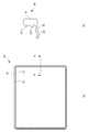
- FIG. 2 is a (a) rear view of the first packing 30, and (b) a sectional view taken along the line AA.
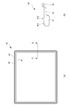
- FIG. 3 is a (a) rear view of the second packing 40 and (b) a sectional view taken along the line B-B.
- the 1st packing 30 and the 2nd packing 40 have a rectangular frame shape corresponding to the shape of opening 11 of lid 20 or container main part 10, as shown in Drawing 2 (a) and Drawing 3 (a).
- the present invention is not limited to this, and may be, for example, annular.
- the first packing 30 is positioned at the first body portion 31 fitted in the first mounting groove 18, the first extending piece 32 extended from the first body portion 31, and the tip of the first extending piece 32. , And the first seal portion 33 extending in a curved manner.
- the first main body portion 31 is formed in a frame shape similar to that of the first mounting groove 18, and has a substantially rectangular shape so that the cross section thereof substantially corresponds to the cross sectional shape of the first mounting groove 18. Further, the first fitting protrusion 311 and the second fitting protrusion 312 are respectively formed in the first main body portion 31 in a tapered manner, and at positions corresponding to the back side of the first attachment groove 18 The second fitting projections 312 are formed side by side at positions corresponding to the opening sides of the first attachment grooves 18.
- the first extension piece 32 is extended toward the inside of the rectangular frame so as to make a substantially right angle with the first main body portion 31.
- the first seal portion 33 reliably contacts the first seal surface 22, the first extension piece 32 is at the first main body portion at an angle other than a right angle. It may be extended from 31.
- the first seal portion 33 is bent and extended so as to be convex toward the lid 20 (see also FIG. 4).
- the first seal portion 33 preferably has a thickness of about 0.6 mm, but is not particularly limited as long as there is no problem in molding.
- the second packing 40 is provided at the tip of the second main body 41 fitted in the second mounting groove 28, the second extension piece 42 extending from the second main body 41, and the second extension piece 42. It is formed of a second seal portion 43 which is positioned and bent.
- the second main body portion 41 is formed in a frame shape similar to that of the second mounting groove 28, and has a substantially rectangular shape so that the cross section thereof substantially corresponds to the cross sectional shape of the second mounting groove 28.
- the first fitting projection 411 and the second fitting projection 412 are respectively formed in the second main body portion 41 in a tapered manner, and at a position corresponding to the back side of the second attachment groove 28.
- the second fitting projections 412 are formed side by side at positions corresponding to the opening sides of the second attachment grooves 28.
- the second extending pieces 42 extend outward in a rectangular frame shape substantially in parallel with the second main body portion 41. However, when the lid 20 is attached to the container main body 10, the second extending piece 42 is not parallel to the second main portion 41 if the second seal portion 43 reliably contacts the second sealing surface 12 It may be extended outside.
- the second seal portion 43 bends and extends so as to be convex toward the container body 10 (see also FIG. 4).
- the second seal portion 43 preferably has a thickness of about 0.6 mm, but is not particularly limited as long as there is no problem in molding.
- the heights of the first seal portion 33 and the second seal portion 43 can be obtained. So that the inner peripheral side of the first main body portion 31 is slightly smaller (approximately 1% to 5%) than the annular peripheral surface on the inner side of the first attachment groove 18, and the second main body The inner peripheral side of the portion 41 is formed to be slightly smaller (about 1 to 5%) than the annular peripheral surface of the bottom of the second mounting groove 28.
- thermoplastic elastomers composed of polyester-based elastomers, polyolefin-based elastomers, fluorine-based elastomers, urethane-based elastomers, fluororubbers, ethylene-propylene rubbers, silicone-baseds
- An elastic body such as rubber
- these materials include fillers such as carbon, glass fiber, mica, talc, silica, calcium carbonate, etc., and resins such as polyethylene, polyamide, polyacetal, fluorocarbon resin, silicone resin, etc. A predetermined amount may be selectively added.
- the hardness of the first packing 30 and the second packing 40 is preferably 40 degrees to 90 degrees in Shore A hardness, and more preferably 60 degrees to 90 degrees.
- the first packing 30 and the second packing 40 may be formed of the same material or may be formed of different materials.
- the sealing performance as the packing P can be improved to about twice.
- the function of the packing P can be improved by utilizing the characteristics possessed by the respective materials.
- Table 1 shows an example of the material.
- the packing P does not transmit water. And sealability can be improved.
- the second packing 40 is made of an olefin-based or styrene-based elastomer, even if the first packing 30 is made of a polyester-based elastomer, the inside of the substrate storage container 1 is cleaned as the packing P.
- the degree of deterioration may be a little worse as long as no problems occur, but the sealing performance can be improved without the permeation of water.
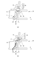
- FIG. 4 is an enlarged sectional view showing (a) a state immediately before closing and (b) a closed state in the vicinity of the opening 11 in the substrate storage container 1 of the embodiment.
- FIG. 5 is an enlarged sectional view showing (a) a state immediately before closing and (b) a closed state in the vicinity of the opening 11 in the conventional substrate storage container 1.
- the white arrows indicate the flow of gas when the inside of the substrate storage container 1 is positive pressure
- the solid arrows indicate the flow of gas when the inside is negative pressure.
- the lid 20 is attached so as to close the opening 11 of the container main body 10, and in the state of FIG. 4 (b), the first seal portion 33 of the first packing 30
- the first seal portion 33 is pressed against the first seal surface 22 while being in contact with the first seal surface 22 of the lid 20 and being deformed together with the first extending piece 32.
- the second seal portion 43 of the second packing 40 contacts the second seal surface 12 of the container main body 10 and deforms together with the second extension piece 42. It is pressed.
- the 2nd seal part 43 of the 2nd packing 40 is the 1st seal face which the 1st seal part 33 contacts.
- the first packing 30 and the second packing 40 are arranged so as to overlap each other.
- the first seal portion 33 of the first packing 30 is further pressed against the first seal surface 22 and closely adhered, so that the gas leaks from the inside. Can be reduced.
- the second seal portion 43 of the second packing 40 is further pressed against the second seal surface 12 and closely attached, so that dust, moisture, etc. from the outside Intrusion can be reduced.
- the sealing property of the substrate storage container 1 (the container main body 10 and the lid 20) can be maintained.
- first seal portion 33 and the second seal portion 43 are respectively displaced along the closing direction H of the lid 20 and come into contact with the first seal surface 22 or the second seal surface 12, the first seal portion 33 And the second seal portion 43 does not move substantially in the direction substantially orthogonal to the closing direction H, and the first packing 30 and the second packing 40 slide on the first sealing surface 22 or the second sealing surface 12 It is possible to reduce the generation of particles due to the phenomenon.
- the substrate storage container 1 includes the container body 10 for storing the substrate W, the lid 20 for closing the opening 11 of the container body 10, and the lid 20.
- the substrate storage container 1 includes the locking mechanism 23 locked to the locked portion 19 of the main body 10, and the packing P interposed between the container main body 10 and the lid 20, wherein the packing P is
- the first packing 30 and the second packing 40 include a first packing 30 attached to the container body 10 and a second packing 40 attached to the lid 20.
- the first packing 30 and the second packing 40 are perpendicular to the closing direction H of the lid 20. When viewed, it is located more inside the container body 10 than the position of the locked portion 19.
- the first seal portion 33 closely contacts the first seal surface 22 against the positive pressure inside the substrate storage container 1 to ensure the airtightness of the substrate storage container 1 from the inside. Gas leakage can be reduced.
- the second seal portion 43 against negative pressure inside the substrate storage container 1, the second seal portion 43 is in close contact with the second seal surface 12 to ensure the airtightness of the substrate storage container 1, and dust and moisture from the outside can be secured. Etc. can be reduced.
- the packing P is provided with the first packing 30 and the second packing 40, the function of the packing P, for example, the sealability and cleanliness against positive pressure or negative pressure, can be obtained by combining them taking advantage of the respective material characteristics.
- the adhesion of the packing P to the contact surface, the low permeability of water, and the like can be improved.
- FIG. 5 is an enlarged cross-sectional view showing a closed state in the vicinity of the opening in the substrate storage container 1 of the modification 1.
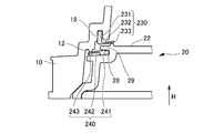
- FIG. 6 is an enlarged cross-sectional view showing a closed state in the vicinity of the opening in the substrate storage container 1 of the second modification.
- FIG. 7 is an enlarged sectional view showing a closed state in the vicinity of the opening in the substrate storage container 1 of the third modification.
- the first extension piece 132 and the first seal portion 133 of the first packing 130 and the second extension piece 142 and the second seal portion 143 of the second packing 140 are the above-described ones. It differs from the first packing 30 and the second packing 40 of the embodiment.
- the first extension piece 132 is extended toward the inside of the rectangular frame so as to make a substantially right angle with the first main body portion 131, and the first seal portion 133 is substantially perpendicular to the lid 20 ( That is, it is formed at the tip bent in the closing direction H) (see FIG. 5). Further, the second extending piece 142 extends outward substantially in parallel with the second main body portion 141, and the second seal portion 143 is substantially perpendicular to the lid 20 (that is, in the closing direction H). It is formed with a bent tip.
- the first seal portion 133 and the second seal portion 143 are respectively displaced along the closing direction H of the lid 20 and contact the first seal surface 22 or the second seal surface 12. Therefore, the first seal portion 133 and the second seal portion 143 do not move substantially in the direction substantially orthogonal to the closing direction H. Therefore, generation of particles due to the first packing 130 and the second packing 140 sliding on the first sealing surface 22 or the second sealing surface 12 can be reduced.
- the first extension piece 232 and the first seal portion 233 of the first packing 230, and the second extension piece 242 and the second seal portion 243 of the second packing 240 differs from the 1st packing 30 and the 2nd packing 40 of the above-mentioned embodiment, and also the 1st seal side 22 and the 2nd seal side 12 are formed in the tip of a projection, respectively.
- the first extending piece 232 is extended toward the inside of the rectangular frame so as to make a substantially right angle with the first main body portion 231, and the first seal portion contacts the second seal surface 12 at the tip thereof 233 are formed (see FIG. 6).
- the second extending piece 242 extends outward substantially in parallel with the second main body portion 241, and a second seal portion 143 contacting the first seal surface 22 is formed at the tip thereof. .
- the first seal portion 233 and the second seal portion 243 are respectively displaced along the closing direction H of the lid 20 and contact the first seal surface 22 or the second seal surface 12 Therefore, the first seal portion 233 and the second seal portion 243 do not move substantially in the direction substantially orthogonal to the closing direction H. Therefore, generation of particles due to the first packing 230 and the second packing 240 sliding on the first sealing surface 22 or the second sealing surface 12 can be reduced.
- the first packing 530 is attached to the first attachment groove 18 formed in the direction substantially orthogonal to the closing direction H of the lid 20, according to the above embodiment and the embodiment. It is different.
- the container body 10 of the third modification has a frame-shaped door flange 10A forming the opening 11 as a separate member, and a first attachment groove 18A is formed between the container body 10 and the door flange 10A. .
- a flange portion 18Fb which is partially recessed is formed on the front side of the container main body 10
- a flange portion 18Fa is formed on the back side of the door flange 10A.
- the front side of the flange portion 18Fa of the door flange 10A is formed as a second sealing surface 12A.
- the container body 10 and the door flange 10A are connected and fixed by a fitting unit, a locking unit, a fixing unit, and the like not shown.
- the first packing 530 is attached to a first mounting groove 18A formed between the flanges 18Fa and 18Fb, and also acts as a seal between the container body 10 and the door flange 10A.
- substrate storage container 1 of the modification 3 can arrange
- the second seal surface 12 and the first seal surface 22 may be subjected to embossing in order to prevent sticking of the first packing 30 and the second packing 40.
Landscapes
- Engineering & Computer Science (AREA)
- Mechanical Engineering (AREA)
- Packaging Frangible Articles (AREA)
- Container, Conveyance, Adherence, Positioning, Of Wafer (AREA)
Abstract
Description
(2)上記(1)の態様において、前記容器本体は、前記第1パッキンを取り付ける第1取付溝と、前記第2パッキンを接触させる第2シール面と、が形成され、前記蓋体は、前記第2パッキンを取り付ける第2取付溝と、前記第1パッキンを接触させる第1シール面と、が形成され、前記第1シール面及び前記第2シール面は、前記蓋体の閉止方向に直交する面で形成されてもよい。
(3)上記(1)又は(2)の態様において、前記第1パッキン及び前記第2パッキンは、前記蓋体の閉止方向から見たとき、互いに重なるように配置されてもよい。
(4)上記(1)から(3)までのいずれか1つの態様において、前記第1パッキンと前記第2パッキンとは、同じ材料で形成されてもよい。
(5)上記(1)から(3)までのいずれか1つの態様において、前記第1パッキンと前記第2パッキンとは、異なる材料で形成されてもよい。
図1に示すように、基板収納容器1は、基板Wを収納する容器本体10と、容器本体10の開口11を閉止する蓋体20と、容器本体10と蓋体20との間に設けられる(介在される)環状のパッキンPと、を備えている。なお、パッキンPについては、後述するように、容器本体10に取り付けられる第1パッキン30と、蓋体20に取り付けられる第2パッキン40と、を含んでいる。
第1パッキン30及び第2パッキン40は、図2(a)及び図3(a)に示すように、蓋体20又は容器本体10の開口11の形状に対応した矩形枠状を有しているが、これに限定されず、例えば、円環状であってもよい。

図4は、実施形態の基板収納容器1における開口11付近の、(a)閉止直前の状態、(b)閉止状態、を示す拡大断面図である。図5は、従来の基板収納容器1における開口11付近の、(a)閉止直前の状態、(b)閉止状態、を示す拡大断面図である。なお、白抜き矢印は、基板収納容器1の内部が陽圧であるときの気体の流れを示し、実線矢印は、内部が陰圧であるときの気体の流れを示している。
ここで、各種の変形例1から3について説明する、図5は、変形例1の基板収納容器1における開口付近の閉止状態を示す拡大断面図である。図6は、変形例2の基板収納容器1における開口付近の閉止状態を示す拡大断面図である。図7は、変形例3の基板収納容器1における開口付近の閉止状態を示す拡大断面図である。
10 容器本体
11 開口、12 第2シール面、13 支持体、14 ロボティックフランジ、15 マニュアルハンドル、16 給気部、17 排気部、18 第1取付溝、19 係止穴(被係止部)
20 蓋体、22 第1シール面、23 施錠機構、24 係止爪、28 第2取付溝、29 凸部
P パッキン、
30,130,230,30A 第1パッキン、31,131,231,531 第1本体部、32,132,232,532 第1延出片、33,133,233,533 第1シール部、311 第1の嵌合突起、312 第2の嵌合突起
40,140,240 第2パッキン、41,141,241,541 第2本体部、42,142,242,542 第2延出片、43,143,243,543 第2シール部、411 第1の嵌合突起、412 第2の嵌合突起
W 基板
H 閉止方向
Claims (5)
- 基板を収納する容器本体と、
前記容器本体の開口を閉止する蓋体と、
前記蓋体に設けられ、前記容器本体の被係止部に係止される施錠機構と、
前記容器本体及び前記蓋体との間に介在されるパッキンと、
を備える基板収納容器であって、
前記パッキンは、前記容器本体に取り付けられる第1パッキンと、前記蓋体に取り付けられる第2パッキンと、を含み、
前記第1パッキン及び前記第2パッキンは、前記蓋体の閉止方向に直交する方向から見たとき、前記被係止部の位置よりも、前記容器本体の内側に位置する
ことを特徴とする基板収納容器。 - 前記容器本体は、前記第1パッキンを取り付ける第1取付溝と、前記第2パッキンを接触させる第2シール面と、が形成され、
前記蓋体は、前記第2パッキンを取り付ける第2取付溝と、前記第1パッキンを接触させる第1シール面と、が形成され、
前記第1シール面及び前記第2シール面は、前記蓋体の閉止方向に直交する面で形成されている
ことを特徴とする請求項1に記載の基板収納容器。 - 前記第1パッキン及び前記第2パッキンは、前記蓋体の閉止方向から見たとき、互いに重なるように配置されている
ことを特徴とする請求項1又は2に記載の基板収納容器。 - 前記第1パッキンと前記第2パッキンとは、同じ材料で形成されている
ことを特徴とする請求項1から3までのいずれか1項に記載の基板収納容器。 - 前記第1パッキンと前記第2パッキンとは、異なる材料で形成されている
ことを特徴とする請求項1から3までのいずれか1項に記載の基板収納容器。
Priority Applications (4)
| Application Number | Priority Date | Filing Date | Title |
|---|---|---|---|
| KR1020207003259A KR102517257B1 (ko) | 2017-07-07 | 2018-06-19 | 기판 수납 용기 |
| US16/628,644 US11211275B2 (en) | 2017-07-07 | 2018-06-19 | Substrate storage container |
| JP2019527617A JP7143560B2 (ja) | 2017-07-07 | 2018-06-19 | 基板収納容器 |
| CN201880044858.4A CN110870055B (zh) | 2017-07-07 | 2018-06-19 | 基板收纳容器 |
Applications Claiming Priority (2)
| Application Number | Priority Date | Filing Date | Title |
|---|---|---|---|
| JP2017-133708 | 2017-07-07 | ||
| JP2017133708 | 2017-07-07 |
Publications (1)
| Publication Number | Publication Date |
|---|---|
| WO2019009065A1 true WO2019009065A1 (ja) | 2019-01-10 |
Family
ID=64949888
Family Applications (1)
| Application Number | Title | Priority Date | Filing Date |
|---|---|---|---|
| PCT/JP2018/023311 Ceased WO2019009065A1 (ja) | 2017-07-07 | 2018-06-19 | 基板収納容器 |
Country Status (6)
| Country | Link |
|---|---|
| US (1) | US11211275B2 (ja) |
| JP (1) | JP7143560B2 (ja) |
| KR (1) | KR102517257B1 (ja) |
| CN (1) | CN110870055B (ja) |
| TW (1) | TWI765065B (ja) |
| WO (1) | WO2019009065A1 (ja) |
Cited By (1)
| Publication number | Priority date | Publication date | Assignee | Title |
|---|---|---|---|---|
| WO2024029016A1 (ja) * | 2022-08-04 | 2024-02-08 | ミライアル株式会社 | 基板収納容器及びその蓋体 |
Families Citing this family (5)
| Publication number | Priority date | Publication date | Assignee | Title |
|---|---|---|---|---|
| CN110770889B (zh) * | 2017-04-06 | 2023-10-27 | 未来儿股份有限公司 | 基板收纳容器 |
| US11302548B2 (en) * | 2017-06-01 | 2022-04-12 | Shin-Etsu Polymer Co., Ltd. | Substrate storage container |
| EP4356420A4 (en) * | 2021-06-14 | 2025-06-11 | Entegris, Inc. | SUBSTRATE CONTAINER WITH DOOR SEAL |
| US12354897B2 (en) * | 2022-05-10 | 2025-07-08 | Entegris, Inc. | Substrate container with door gasket |
| TWI904751B (zh) * | 2024-02-06 | 2025-11-11 | 家登精密工業股份有限公司 | 半導體工件傳送箱 |
Citations (3)
| Publication number | Priority date | Publication date | Assignee | Title |
|---|---|---|---|---|
| JPS5695857A (en) * | 1979-12-14 | 1981-08-03 | Mauser Werke Gmbh | Vessel with cover |
| JPH10245066A (ja) * | 1997-03-06 | 1998-09-14 | Komatsu Kasei Kk | 合成樹脂製容器の密閉構造と密閉用ガスケット |
| JP2009302414A (ja) * | 2008-06-17 | 2009-12-24 | Shin Etsu Polymer Co Ltd | 基板収納容器 |
Family Cites Families (16)
| Publication number | Priority date | Publication date | Assignee | Title |
|---|---|---|---|---|
| US5469963A (en) * | 1992-04-08 | 1995-11-28 | Asyst Technologies, Inc. | Sealable transportable container having improved liner |
| JPH11154699A (ja) * | 1997-11-21 | 1999-06-08 | Shin Etsu Polymer Co Ltd | 容器の封止構造 |
| US6464081B2 (en) * | 1999-01-06 | 2002-10-15 | Entegris, Inc. | Door guide for a wafer container |
| JP3769417B2 (ja) * | 1999-06-30 | 2006-04-26 | 株式会社東芝 | 基板収納容器 |
| JP3556185B2 (ja) | 2000-06-13 | 2004-08-18 | 信越ポリマー株式会社 | シール部材、密封容器及びそのシール方法 |
| US7413099B2 (en) | 2001-06-08 | 2008-08-19 | Shin-Etsu Polymer Co., Ltd. | Sealing element with a protruding part approximately obliquely outward and a hermetic container using the same |
| JP4223715B2 (ja) * | 2001-12-04 | 2009-02-12 | ミライアル株式会社 | 薄板用収納・保管容器 |
| JP4482655B2 (ja) * | 2005-04-22 | 2010-06-16 | ゴールド工業株式会社 | 精密基板収納容器のガスケット |
| US20070175792A1 (en) * | 2006-02-02 | 2007-08-02 | Barry Gregerson | Magnetic seal for wafer containers |
| SG172631A1 (en) * | 2006-05-29 | 2011-07-28 | Shinetsu Polymer Co | Substrate storage container |
| JP2010003948A (ja) | 2008-06-23 | 2010-01-07 | Shin Etsu Polymer Co Ltd | 基板収納容器 |
| JP5281697B2 (ja) * | 2010-01-26 | 2013-09-04 | ミライアル株式会社 | 半導体ウエハ収納容器 |
| JP6114193B2 (ja) * | 2010-10-20 | 2017-04-12 | インテグリス・インコーポレーテッド | ドア・ガイドおよびシールを備えたウェーハ容器 |
| JP2015521377A (ja) * | 2012-05-04 | 2015-07-27 | インテグリス・インコーポレーテッド | ドア接点シールを有するウェハ容器 |
| JP5989110B2 (ja) * | 2012-06-15 | 2016-09-07 | ミライアル株式会社 | 埃などの侵入を抑制する基板収納容器 |
| JP6313873B2 (ja) * | 2017-02-27 | 2018-04-18 | 東京エレクトロン株式会社 | 密閉容器及び搬送システム |
-
2018
- 2018-06-19 KR KR1020207003259A patent/KR102517257B1/ko active Active
- 2018-06-19 US US16/628,644 patent/US11211275B2/en active Active
- 2018-06-19 CN CN201880044858.4A patent/CN110870055B/zh active Active
- 2018-06-19 JP JP2019527617A patent/JP7143560B2/ja active Active
- 2018-06-19 WO PCT/JP2018/023311 patent/WO2019009065A1/ja not_active Ceased
- 2018-07-05 TW TW107123260A patent/TWI765065B/zh active
Patent Citations (3)
| Publication number | Priority date | Publication date | Assignee | Title |
|---|---|---|---|---|
| JPS5695857A (en) * | 1979-12-14 | 1981-08-03 | Mauser Werke Gmbh | Vessel with cover |
| JPH10245066A (ja) * | 1997-03-06 | 1998-09-14 | Komatsu Kasei Kk | 合成樹脂製容器の密閉構造と密閉用ガスケット |
| JP2009302414A (ja) * | 2008-06-17 | 2009-12-24 | Shin Etsu Polymer Co Ltd | 基板収納容器 |
Cited By (1)
| Publication number | Priority date | Publication date | Assignee | Title |
|---|---|---|---|---|
| WO2024029016A1 (ja) * | 2022-08-04 | 2024-02-08 | ミライアル株式会社 | 基板収納容器及びその蓋体 |
Also Published As
| Publication number | Publication date |
|---|---|
| TW201906775A (zh) | 2019-02-16 |
| TWI765065B (zh) | 2022-05-21 |
| JP7143560B2 (ja) | 2022-09-29 |
| KR102517257B1 (ko) | 2023-04-04 |
| KR20200028409A (ko) | 2020-03-16 |
| CN110870055B (zh) | 2023-09-08 |
| JPWO2019009065A1 (ja) | 2020-04-30 |
| US20200185244A1 (en) | 2020-06-11 |
| US11211275B2 (en) | 2021-12-28 |
| CN110870055A (zh) | 2020-03-06 |
Similar Documents
| Publication | Publication Date | Title |
|---|---|---|
| WO2019009065A1 (ja) | 基板収納容器 | |
| CN110709981B (zh) | 基板收纳容器 | |
| KR100904799B1 (ko) | 밀봉 용기 | |
| US11450543B2 (en) | Substrate storage container | |
| TW201909318A (zh) | 基板收納容器 | |
| JP5888492B2 (ja) | 基板収納容器 | |
| US11230427B2 (en) | Substrate storage container with umbrella-shaped seal lip | |
| JPWO2019031142A1 (ja) | 基板収納容器及びその製造方法 | |
| JP6915203B2 (ja) | 基板収納容器 | |
| JP7073599B2 (ja) | 基板収納容器 | |
| JP7247439B2 (ja) | 基板収納容器 | |
| JP7607278B2 (ja) | 基板収納容器 | |
| JP7519281B2 (ja) | 基板収納容器 | |
| JP7247440B2 (ja) | 基板収納容器 | |
| TW202537912A (zh) | 基板收納容器以及基板收納容器用的密封構件 | |
| WO2026083716A1 (ja) | 基板収納容器 |
Legal Events
| Date | Code | Title | Description |
|---|---|---|---|
| 121 | Ep: the epo has been informed by wipo that ep was designated in this application |
Ref document number: 18828288 Country of ref document: EP Kind code of ref document: A1 |
|
| ENP | Entry into the national phase |
Ref document number: 2019527617 Country of ref document: JP Kind code of ref document: A |
|
| NENP | Non-entry into the national phase |
Ref country code: DE |
|
| ENP | Entry into the national phase |
Ref document number: 20207003259 Country of ref document: KR Kind code of ref document: A |
|
| 122 | Ep: pct application non-entry in european phase |
Ref document number: 18828288 Country of ref document: EP Kind code of ref document: A1 |