WO2019004177A1 - ヘリコプタ用の潤滑装置 - Google Patents
ヘリコプタ用の潤滑装置 Download PDFInfo
- Publication number
- WO2019004177A1 WO2019004177A1 PCT/JP2018/024131 JP2018024131W WO2019004177A1 WO 2019004177 A1 WO2019004177 A1 WO 2019004177A1 JP 2018024131 W JP2018024131 W JP 2018024131W WO 2019004177 A1 WO2019004177 A1 WO 2019004177A1
- Authority
- WO
- WIPO (PCT)
- Prior art keywords
- oil
- lubrication
- lubricating
- passage
- oil reservoir
- Prior art date
- Legal status (The legal status is an assumption and is not a legal conclusion. Google has not performed a legal analysis and makes no representation as to the accuracy of the status listed.)
- Ceased
Links
Images

Classifications
-
- F—MECHANICAL ENGINEERING; LIGHTING; HEATING; WEAPONS; BLASTING
- F16—ENGINEERING ELEMENTS AND UNITS; GENERAL MEASURES FOR PRODUCING AND MAINTAINING EFFECTIVE FUNCTIONING OF MACHINES OR INSTALLATIONS; THERMAL INSULATION IN GENERAL
- F16H—GEARING
- F16H57/00—General details of gearing
- F16H57/04—Features relating to lubrication or cooling or heating
- F16H57/0412—Cooling or heating; Control of temperature
- F16H57/0415—Air cooling or ventilation; Heat exchangers; Thermal insulations
- F16H57/0417—Heat exchangers adapted or integrated in the gearing
-
- F—MECHANICAL ENGINEERING; LIGHTING; HEATING; WEAPONS; BLASTING
- F16—ENGINEERING ELEMENTS AND UNITS; GENERAL MEASURES FOR PRODUCING AND MAINTAINING EFFECTIVE FUNCTIONING OF MACHINES OR INSTALLATIONS; THERMAL INSULATION IN GENERAL
- F16H—GEARING
- F16H57/00—General details of gearing
- F16H57/04—Features relating to lubrication or cooling or heating
- F16H57/0434—Features relating to lubrication or cooling or heating relating to lubrication supply, e.g. pumps; Pressure control
- F16H57/0442—Features relating to lubrication or cooling or heating relating to lubrication supply, e.g. pumps; Pressure control for supply in case of failure, i.e. auxiliary supply
-
- B—PERFORMING OPERATIONS; TRANSPORTING
- B64—AIRCRAFT; AVIATION; COSMONAUTICS
- B64C—AEROPLANES; HELICOPTERS
- B64C27/00—Rotorcraft; Rotors peculiar thereto
- B64C27/04—Helicopters
- B64C27/12—Rotor drives
-
- F—MECHANICAL ENGINEERING; LIGHTING; HEATING; WEAPONS; BLASTING
- F16—ENGINEERING ELEMENTS AND UNITS; GENERAL MEASURES FOR PRODUCING AND MAINTAINING EFFECTIVE FUNCTIONING OF MACHINES OR INSTALLATIONS; THERMAL INSULATION IN GENERAL
- F16H—GEARING
- F16H57/00—General details of gearing
- F16H57/04—Features relating to lubrication or cooling or heating
- F16H57/042—Guidance of lubricant
- F16H57/0421—Guidance of lubricant on or within the casing, e.g. shields or baffles for collecting lubricant, tubes, pipes, grooves, channels or the like
- F16H57/0423—Lubricant guiding means mounted or supported on the casing, e.g. shields or baffles for collecting lubricant, tubes or pipes
-
- F—MECHANICAL ENGINEERING; LIGHTING; HEATING; WEAPONS; BLASTING
- F16—ENGINEERING ELEMENTS AND UNITS; GENERAL MEASURES FOR PRODUCING AND MAINTAINING EFFECTIVE FUNCTIONING OF MACHINES OR INSTALLATIONS; THERMAL INSULATION IN GENERAL
- F16H—GEARING
- F16H57/00—General details of gearing
- F16H57/04—Features relating to lubrication or cooling or heating
- F16H57/0434—Features relating to lubrication or cooling or heating relating to lubrication supply, e.g. pumps; Pressure control
- F16H57/0441—Arrangements of pumps
-
- F—MECHANICAL ENGINEERING; LIGHTING; HEATING; WEAPONS; BLASTING
- F16—ENGINEERING ELEMENTS AND UNITS; GENERAL MEASURES FOR PRODUCING AND MAINTAINING EFFECTIVE FUNCTIONING OF MACHINES OR INSTALLATIONS; THERMAL INSULATION IN GENERAL
- F16H—GEARING
- F16H57/00—General details of gearing
- F16H57/04—Features relating to lubrication or cooling or heating
- F16H57/045—Lubricant storage reservoirs, e.g. reservoirs in addition to a gear sump for collecting lubricant in the upper part of a gear case
-
- F—MECHANICAL ENGINEERING; LIGHTING; HEATING; WEAPONS; BLASTING
- F16—ENGINEERING ELEMENTS AND UNITS; GENERAL MEASURES FOR PRODUCING AND MAINTAINING EFFECTIVE FUNCTIONING OF MACHINES OR INSTALLATIONS; THERMAL INSULATION IN GENERAL
- F16H—GEARING
- F16H57/00—General details of gearing
- F16H57/04—Features relating to lubrication or cooling or heating
- F16H57/0463—Grease lubrication; Drop-feed lubrication
- F16H57/0465—Drop-feed lubrication
-
- F—MECHANICAL ENGINEERING; LIGHTING; HEATING; WEAPONS; BLASTING
- F16—ENGINEERING ELEMENTS AND UNITS; GENERAL MEASURES FOR PRODUCING AND MAINTAINING EFFECTIVE FUNCTIONING OF MACHINES OR INSTALLATIONS; THERMAL INSULATION IN GENERAL
- F16H—GEARING
- F16H57/00—General details of gearing
- F16H57/04—Features relating to lubrication or cooling or heating
- F16H57/0467—Elements of gearings to be lubricated, cooled or heated
- F16H57/0469—Bearings or seals
- F16H57/0471—Bearing
Definitions
- the present invention relates to a lubricating device for a helicopter.
- a power transmission for a helicopter is required to have a dry run capability that can operate even when oil is shut off. Even with the current technology, the necessary dry run capacity is secured, but with recent trends such as the increase in on-shore operation, it is desirable to further improve the dry run capacity.
- Patent Document 1 As a measure against the current dry run, there is one in which oil for emergency is stored and replenishment is continued at the time of emergency (for example, Patent Document 1).
- the lubrication device includes a main lubrication system that is normally used and an auxiliary lubrication system that is used during dry running.
- the auxiliary lubrication system normally receives oil distribution from the main lubrication system, stores the oil in the tank, and discharges the oil little by little from the tank during dry running.
- the structure becomes complicated.
- an object of this invention is to provide the lubricating device which can aim at the improvement of dry run capability by easy structure.
- a lubricating device comprises an oil sump storing lubricating oil, a lubricating pump for sucking and discharging oil from the oil sump, and a first lubrication target from the lubricating pump. And a lubricating passage leading to the The lubrication passage is formed immediately above the first lubrication target, and a first supply port for supplying oil in the lubrication passage to the first lubrication target, and an oil reservoir provided on the upstream side of the first supply port And an opening provided upstream of the outlet of the oil reservoir and above the outlet of the oil reservoir.
- the oil in the lubrication passage is supplied to the first lubrication target from the first supply port via the oil reservoir. Also, at normal times, the oil reservoir holds a predetermined amount of oil.
- the oil pressure in the lubrication passage is lowered due to a failure such as oil leakage from the connector included in the lubrication passage and it becomes a dry run state, that is, when the oil pressure in the lubrication passage falls to the oil pressure of the oil sump, from the opening Air is taken into the lubricating passage. Then, the oil in the lubricating passage downstream of the opening, which contains the oil in the oil reservoir, is dripped to the first lubrication target directly below the first supply port under the influence of gravity.
- the oil pressure in the oil reservoir is maintained at the same state as the sump pressure of the lubricating device through the opening, so that stable dripping lubrication is realized.
- the common oil reservoir enables normal oil lubrication and dripping lubrication during dry running. Therefore, the dry run capability can be improved with a simple configuration.
- a case may be further provided which accommodates at least the oil sump, the lubrication pump, the first lubrication target, and the oil reservoir, and the opening may be formed in the internal space of the case. According to this configuration, at normal times, the oil can be supplied from the opening to another lubrication target disposed in the internal space of the case.
- the lubrication passage further includes an oil cooler provided on the outside of the case to cool oil in the lubrication passage, and the opening is provided on the downstream side of the oil cooler in the lubrication passage. It may be done. According to this configuration, even if an oil leak occurs from the connection portion of the oil cooler or the oil cooler, the oil is dropped from the first supply port to the first lubrication target immediately below. Therefore, the dry run ability can be improved.
- the lubrication passage may further have a second supply port upstream of the oil reservoir for supplying the oil of the lubrication passage to a second lubrication target.
- the first lubrication target and the second lubrication target may be a rotating member of a transmission, and the first lubrication target may be rotating at a higher speed than the second lubrication target. According to this configuration, it is possible to intensively lubricate the high-speed rotating member, which is particularly required to be lubricated, during the dry run.
- the opening may be provided above the oil reservoir on the upstream side of the oil reservoir in the lubrication passage.
- the oil on the downstream side of the opening on the upstream side of the oil reservoir can also be used for dripping lubrication.
- the opening may be provided between the second supply port and the oil reservoir. According to this configuration, by setting the portion of low priority of lubrication as the second lubrication target, it is possible to effectively lubricate the first lubrication target of high priority of lubrication during the dry run.
- the opening may be provided in the oil reservoir.
- the opening may be provided in the upper wall of the oil reservoir. According to this configuration, the air in the oil reservoir can be effectively exhausted from the opening when the lubricating device is started.
- an auxiliary oil sump for storing spare oil, an auxiliary lubrication pump for sucking and discharging the oil from the auxiliary oil sump, and an auxiliary lubrication passage for connecting the auxiliary lubrication pump and the oil reservoir May be provided.
- this configuration by providing the auxiliary oil sump, it is possible to increase the oil circulation amount at the time of dry run.
- the hydraulic pressure in the lubricating passage may be larger than the hydraulic pressure in the auxiliary lubricating passage when the hydraulic pressure in the lubricating passage is larger than the hydraulic pressure of the oil sump, that is, under normal conditions. .
- the oil pressure of the lubricating passage blocks the connection port to the oil reservoir of the auxiliary lubricating passage, so the auxiliary lubricating passage does not function. Therefore, since oil does not flow in the auxiliary lubricating passage under normal conditions, it is not necessary to provide an oil filter in the auxiliary lubricating passage.
- the auxiliary oil sump is a recess formed in the bottom of the oil sump, and the suction port of the lubricating pump is positioned above the recess in the oil sump.
- the suction port of the auxiliary lubrication pump may be located in the recess.
- At normal time means that the helicopter is operating in a state where lubricating oil is normally supplied and circulated in the power transmission device (transmission) of the helicopter.
- “Dry run time” means the time when the helicopter is operating with the lubricating oil contained in the power transmission device of the helicopter leaking.
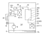
- FIG. 1 shows a lubrication system diagram of a power transmission device of a helicopter provided with a lubricating device LS according to a first embodiment of the present invention.
- the transmission 1 is provided with a transmission gear 4.
- the transmission gear 4 constitutes a rotating member of the transmission 1.
- the transmission gear 4 shifts the rotation of an engine (not shown) and transmits it to the main rotor (not shown) and the tail rotor (not shown).
- the lubrication target T of the lubrication device LS of the present embodiment is a rotating member of the transmission 1 of a helicopter.
- the lubrication target T is the transmission gear 4 and the bearing portion of the rotating shaft provided with the gear.
- the lubrication target T includes a first lubrication target 12 (FIG. 2) and a second lubrication target 14 (FIG. 2).
- the number of lubrication targets T is not limited to this.
- the second lubrication target 14 may be omitted. Further, the number of lubrication targets T may be three or more.
- the first lubrication target 12 rotates at a higher speed than the second lubrication target 14.
- the first lubrication target 12 be the portion of the transmission gear 4 that rotates at the highest speed.
- the first lubrication target 12 is preferably a gear to which rotation of an engine (not shown) is input, and its bearing.
- the lubricating device LS supplies lubricating oil OL to the lubrication target T.
- the lubricating device LS includes an oil sump 6, a lubricating pump 8, and a lubricating passage 10.
- the lubricating device LS includes a case 2 in which at least a part of the lubrication target T, the oil reservoir 26, and the lubricating passage 10 is accommodated.
- the oil sump 6 stores oil OL.
- the oil sump 6 is formed in the lower part of the case 2.
- the oil sump 6 is formed by denting a part (central part) of the bottom wall of the case 2 downward.
- the oil sump 6 is integrally formed with the case 2.
- the configuration of the oil sump 6 is not limited to this.
- a recess may be provided in a part of the side wall of the case 2 and the recess may be the oil sump 6.
- the lubrication pump 8 sucks and discharges the oil OL from the oil sump 6.
- the lubricating pump 8 is disposed in the oil sump 6.
- the lubricating pump 8 does not have to be disposed entirely in the oil sump 6, and a suction port or a pipe connected to the suction port may be disposed in the oil sump 6.
- the lubricating pump 8 is not particularly limited, and is, for example, a gear pump.
- the oil OL discharged from the lubricating pump 8 is supplied to the lubrication target T through the lubricating passage 10.
- the lubricating passage 10 is a passage of oil OL from the lubricating pump 8 to the first lubrication target 12.
- the lubrication passage 10 is provided with various devices in the middle thereof. Further, the lubricating passage 10 is mainly configured by piping.
- the lubricating passage 10 has a supply port 20, an oil reservoir 26, and an opening 28.
- the lubrication passage 10 further includes an oil filter 16 and an oil cooler 18.
- the oil filter 16 is disposed downstream of the lubricating pump 8 to filter the oil OL.
- the oil cooler 18 is disposed downstream of the oil filter 16 to cool the oil OL.
- the oil filter 16 and the oil cooler 18 may be omitted depending on the use conditions.
- the oil filter 16 and the oil cooler 18 are disposed outside the case 2. Specifically, a part of the lubricating passage 10 extending from the lubricating pump 8 penetrates the wall of the case 2 and extends outside the case 2. The oil filter 16 and the oil cooler 18 are provided at a portion of the lubrication passage 10 extending outside the case 2. The lubrication passage 10 extends outside the case 2 and then penetrates the wall of the case 2 to enter the inside of the case 2 to supply oil OL to the object T to be lubricated.
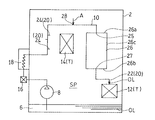
- FIG. 2 shows the lubrication system of FIG. 1 in a simplified manner.
- the supply port 20 supplies the oil OL to the lubrication target T.
- the supply port 20 is formed in the internal space SP of the case 2.
- the supply port 20 has a first supply port 22 for supplying the oil OL to the first lubrication target 12 and a second supply port 24 for supplying the oil OL to the second lubrication target 14.
- the number of supply ports 20 is not limited to this.
- the second lubrication target 14 is omitted, the second supply port 24 may be omitted.
- the supply ports 20 may be three or more.
- the first and second supply ports 22 and 24 are oil injection nozzles.
- the first and second supply ports 22 and 24 are not limited to this.
- the first and second supply ports 22 and 24 may be through holes formed in the pipe wall of the pipe constituting the lubrication passage 10.
- the first supply port 22 is disposed immediately above the first lubrication target 12.
- “disposed immediately above” means the oil OL, which is dropped above the first lubrication target 12 under the influence of gravity from the first supply port 22 during the dry run, to the first lubrication target 12. It means that the first supply port 22 is disposed within the reach range. That is, “directly on” includes a horizontal shift of the range in which the oil OL dropped by gravity reaches the first lubrication target 12. As described above, the first supply port 22 is configured to drop the oil OL onto the first lubrication target at the time of dry run.
- An oil reservoir 26 is provided upstream of the first supply port 22 in the lubrication passage 10. Specifically, an oil reservoir 26 is provided upstream of the first supply port 22 in the lubricating passage 10 and downstream of the second supply port 24. At normal times, the oil reservoir 26 holds the oil OL inside. At the time of dry run, the oil OL inside the oil reservoir 26 is dropped to the first lubrication target 12 via the first supply port 22.
- the volume of the oil reservoir 26 is appropriately set according to the required dry run capacity.
- the oil reservoir 26 is configured as a box-like tank. However, the configuration of the oil reservoir is not limited to this.
- the oil reservoir 26 may be formed by increasing the diameter of the pipe that constitutes the lubrication passage 10.
- the oil reservoir 26 is formed to have a larger passage area (cross-sectional area) than the pipes before and after it, and the storage amount of oil OL per unit length (the same length) is larger than that before and after the pipe It is formed large.
- the oil reservoir 26 may be provided integrally with the side wall or the upper wall of the case 2.
- the inlet 25 is formed in the upper wall 26 a of the box-like oil reservoir 26, and the outlet 27 is formed in the lower wall 26 b. That is, the lubricating passage 10 connected to the opening 28 is connected to the upper wall 26 a of the oil reservoir 26, and the lubricating passage 10 connected to the first supply port 22 is connected to the lower wall 26 b of the oil reservoir 26.
- the configuration of the oil reservoir is not limited to this.
- the outlet 27 of the oil reservoir 26 may be provided at the lower portion of the side wall 26c instead of the lower wall 26b.
- An opening 28 is provided upstream of the outlet 27 of the oil reservoir 26 in the lubricating passage 10 and above the outlet 27 of the oil reservoir 26.
- an opening 28 is provided on the upstream side of the oil reservoir 26 in the lubrication passage 10 and above the oil reservoir 26.
- the opening 28 may be located higher than the outlet 27 of the oil reservoir 26, and may be provided in the oil reservoir 26 itself. Even when the opening 28 is provided in the lubricating passage 10 upstream of the oil reservoir 26 as in the present embodiment, it is not necessary to be directly above the oil reservoir 26. That is, "upper” in this case means above (in the high position) in the vertical direction, and the oil reservoir 26 and the opening 28 may be arranged horizontally offset.
- the opening 28 is formed in the internal space SP of the case 2.
- the opening 28 is provided on the downstream side of the oil cooler 18 between the second supply port 24 and the oil reservoir 26.
- the opening 28 is normally configured to eject the oil OL. Therefore, if the lubrication target T is disposed downstream of the opening 28, the lubrication target T can be lubricated at normal times.
- the opening 28 Air is introduced into the lubricating passage 10.
- the opening 28 is a through hole provided in a pipe that constitutes the lubrication passage 10.
- the opening 28 is not limited to this.
- the opening 28 may be a hole of a projecting nozzle provided in a pipe. If the opening 28 is a nozzle, it is possible to accurately supply a part of the oil from the opening 28 to the lubrication target T at normal times.
- the opening 28 is disposed above at least the outlet 27 of the oil reservoir 26 and above the first supply port 22.
- the opening 28 is preferably disposed above the upper surface of the oil reservoir 26 (upper wall 26 a) or the upper surface of the oil reservoir 26.
- the lubrication passage 10 between the opening 28 and the oil reservoir 26 may be partially located above the opening 28.
- the oil OL in the portion located above the opening 28 in the lubricating passage 10 flows back and flows out from the opening 28.
- the lubricating passage 10 between the opening 28 and the oil reservoir 26 is preferably located below the opening 28.
- the first supply port 22 is disposed below at least the upper surface (upper wall 26 a) of the oil reservoir 26 and below the opening 28.
- the first supply port 22 is preferably disposed below the bottom surface (lower wall 26 b) of the oil reservoir 26. From the above, it is preferable that the opening 28 be disposed above the upper surface of the oil reservoir 26 or the upper surface of the oil reservoir 26, and the first supply port 22 be disposed below the bottom surface of the oil reservoir 26.
- FIG. 2 shows the flow of the oil OL at the normal time
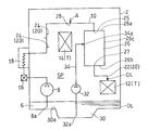
- FIG. 3 shows the flow of the oil OL at the dry run time.
- the oil OL in the oil sump 6 is sucked and discharged by the lubricating pump 8.
- the oil OL discharged from the lubricating pump 8 is supplied to the lubrication target T through the lubricating passage 10.
- the flow of the oil OL at the normal time in the present embodiment will be described in detail.
- the oil OL discharged by the lubricating pump 8 is filtered by the oil filter 16 outside the case 2 and then cooled by the oil cooler 18.
- the oil OL cooled by the oil cooler 18 is returned to the inside of the case 2 and a part thereof is supplied to the second lubrication target 14 from the second supply port 24.
- the oil OL is injected from the second supply port 24 in response to the oil pressure in the lubricating passage 10.
- the oil OL further flows in the lubricating passage 10 and a portion thereof is injected from the opening 28 into the internal space SP of the case 2.
- the remainder of the oil OL further flows in the lubricating passage 10 and reaches the oil reservoir 26.
- the oil reservoir 26 holds a predetermined amount of oil OL.
- the oil OL that has passed through the oil reservoir 26 is supplied from the first supply port 22 to the first lubrication target 12. Under normal conditions, the oil OL is injected from the first supply port 22 in response to the oil pressure in the lubricating passage 10.
- the oil OL supplied from the first and second supply ports 22 and 24 and the oil OL injected from the opening 28 are recovered in the oil sump 6 after lubricating the first lubrication target 12 and the second lubrication target 14 .
- the oil pressure P3 in the oil reservoir 26 is maintained in the same state as the pressure P2 of the oil sump 6 (internal space SP) through the opening 28, so that stable dripping lubrication is realized. At this time, since the pressure of the oil OL located upstream of the opening 28 of the lubricating passage 10 is reduced, the oil supply from the second supply port 24 to the second lubrication target 14 is stopped.
- the oil OL in the lubricating passage 10 is supplied to the first lubrication target 12 from the first supply port 22 via the oil reservoir 26 in the normal state of FIG. Also, at a normal time, the oil reservoir 26 holds a predetermined amount of oil OL.
- air A is taken into the lubricating passage 10 from the opening 28. Then, the oil OL in the oil reservoir 26 and the oil OL in the lubricating passage 10 between the opening 28 and the oil reservoir 26 are dropped from the first supply port 22 to the first lubrication target 12 under the influence of gravity. .
- the common oil reservoir 26 enables normal oil lubrication and dripping lubrication during dry running. Therefore, the dry run capability can be improved with a simple configuration.
- the oil sump 6, the lubrication pump 8, the lubrication target T, and the oil reservoir 26 are accommodated in the case 2, and an opening 28 is formed in the internal space SP of the case 2.
- the oil OL injected from the opening 28 can be supplied to the lubrication target T disposed in the internal space SP of the case 2.
- An opening 28 of the lubricating passage 10 is provided on the downstream side of an oil cooler 18 provided outside the case 2. Therefore, during normal times, the oil OL after cooling by the oil cooler 18 can be supplied to the first lubrication target 12, and from between the oil cooler 18 and the oil reservoir 26 in the lubrication passage 10 to the second lubrication target 14. The oil OL after cooling can be supplied.
- a second supply port 24 for supplying the oil OL to the second lubrication target 14 is provided on the upstream side of the oil reservoir 26 in the lubrication passage 10, and an opening 28 is provided between the second supply port 24 and the oil reservoir 26. ing. As a result, during the dry run, it is possible to effectively lubricate the first lubrication target 12 having a high degree of lubrication priority.
- the first lubrication target 12 and the second lubrication target 14 are rotation members of the transmission, and the high-speed rotation member rotating at a speed higher than that of the second lubrication target 14 is the first lubrication target 12. It is possible to intensively lubricate a high speed rotating member having a high priority of lubrication.
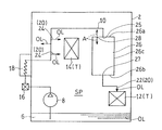
- FIG. 4 is a system diagram showing a lubricating system of a lubricating device according to a second embodiment of the present invention in a simplified manner.
- the lubricating device LS of the second embodiment differs from the first embodiment in that it includes an auxiliary oil sump 30, an auxiliary lubrication pump 32, and an auxiliary lubrication passage 34.
- the auxiliary oil sump 30 stores spare oil OL.
- the spare oil OL is supplied to the lubrication target T at the time of dry run.
- the auxiliary oil sump 30 of the present embodiment is formed below the bottom of the oil sump 6.
- the auxiliary oil sump 30 is composed of a recess formed in the bottom of the oil sump 6.
- the configuration of the auxiliary oil sump 30 is not limited to this.
- the suction port 8 a of the lubricating pump 8 is located above the upper edge 30 a (the same height as the bottom surface of the oil sump 6) of the recess 30 in the oil sump 6.
- the auxiliary lubrication pump 32 sucks and discharges the oil OL from the auxiliary oil sump 30.
- the suction port 32 a of the auxiliary lubrication pump 32 is located below the upper edge 30 a of the recess 30, that is, in the recess 30. Therefore, the upper edge 30 a of the recess 30 is located above the suction port 32 a of the auxiliary lubrication pump 32.
- the upper and lower portions herein refer to the upper and lower positions in the vertical direction, and the horizontal position does not matter.
- the auxiliary lubrication pump 32 may be a centrifugal centrifugal pump in order to suppress an increase in the hydraulic pressure P4 in the auxiliary lubrication passage 34.
- the auxiliary lubrication passage 34 connects the auxiliary lubrication pump 32 and the oil reservoir 26.
- the auxiliary lubrication passage 34 and the oil reservoir 26 are connected by the connection port 34 a.
- no oil filter is provided in the auxiliary lubrication passage 34.
- the oil pressure P1 in the lubrication passage 10 at the normal time is set larger than the oil pressure P4 in the auxiliary lubrication passage 34.
- the hydraulic pressure P4 in the auxiliary lubrication passage 34 is set to be larger than the pressure P2 of the oil sump 6 (the internal space SP).
- a relief valve may be provided in the auxiliary lubrication passage 34 in order to suppress an increase in the hydraulic pressure P4 in the auxiliary lubrication passage 34.
- the other configuration is the same as that of the first embodiment.
- the hydraulic pressure P1 in the lubricating passage 10 is larger than the pressure P2 of the oil sump 6 (internal space SP) and larger than the hydraulic pressure P4 in the auxiliary lubricating passage 34. That is, the discharge pressure of the lubrication pump 8 is larger than the discharge pressure of the auxiliary lubrication pump 32.
- the oil pressure P1 in the lubricating passage 10 is pushed to close the connection port 34a from the auxiliary lubricating passage 34 to the oil reservoir 26 so that oil is supplied to the oil reservoir 26. I can not do it. Therefore, the flow of the oil OL at the normal time is the same as that of the first embodiment described above.
- the auxiliary lubrication passage 34 is preferably configured to communicate with the oil reservoir 26 only during dry running.
- the oil OL is supplied from the auxiliary lubrication passage 34 to the oil reservoir 26 at the time of dry run, the oil circulation amount at the time of dry run can be increased. Therefore, the dry run ability can be further improved.
- the hydraulic pressure P1 in the lubricating passage 10 is set larger than the hydraulic pressure P4 in the auxiliary lubricating passage 34. That is, under normal conditions, the auxiliary lubricating passage 34 does not function due to the hydraulic pressure P1 of the lubricating passage 10. Therefore, it is not necessary to provide an oil filter in the auxiliary lubrication passage 34, and the number of parts can be reduced. In normal times, the clean oil OL that has passed through the oil filter 16 disposed downstream of the lubricating pump 8 is distributed to each part. The oil filter 16 contributes to prolonging the life of gears and bearings, but since the oil supply during dry run is extremely short, the omission of the oil filter has almost no influence on the life.
- the auxiliary oil sump 30 is formed of a recess formed in the bottom of the oil sump 6, the lubricating device LS can be made compact. By setting the depths of the oil sumps 6, 30 in two steps, it is easy to secure the oil OL at the dry run time.
- the auxiliary lubrication pump 32 can also reuse the oil OL recovered at the time of dry run.
- FIG. 5 is a system diagram showing a lubricating system of a lubricating device according to a third embodiment of the present invention in a simplified manner.
- the position of the opening 28 of the lubricating device LS of the third embodiment is different from that of the first embodiment.
- the opening 28 is formed in the upper surface (upper wall 26 a) of the oil reservoir 26.
- the opening 28 may be formed on the top of the side wall 26 c of the oil reservoir 26, preferably above 2/3 of the height of the oil reservoir 26.
- the other configuration is the same as that of the lubricating device LS of the first embodiment.
- one or more of the oil filter 16, the oil cooler 18, and the second supply port 24 may be omitted depending on the situation. Furthermore, the auxiliary oil sump 30, the auxiliary lubrication pump 32, and the auxiliary lubrication passage 34 of the second embodiment may be introduced into the lubricating device LS of the third embodiment.
- the oil reservoir 26 holds a predetermined amount of oil OL.
- the air A in the oil reservoir 26 is discharged from the opening 28 of the upper wall 26 a to the outside of the oil reservoir 26. Therefore, it is possible to prevent an air reservoir from being formed inside the oil reservoir 26. As a result, the volume of the oil reservoir 26 can be used effectively.
- the oil OL that has passed through the oil reservoir 26 is supplied from the first supply port 22 to the first lubrication target 12.
- the opening 28 is not limited to the through hole provided in the pipe that constitutes the lubricating passage 10, and may be a projecting nozzle.
- the oil OL can be supplied to the lubrication target T from the opening 28 at normal times. Therefore, such is also included in the scope of the present invention.
Landscapes
- Engineering & Computer Science (AREA)
- General Engineering & Computer Science (AREA)
- Mechanical Engineering (AREA)
- Aviation & Aerospace Engineering (AREA)
- General Details Of Gearings (AREA)
Priority Applications (3)
| Application Number | Priority Date | Filing Date | Title |
|---|---|---|---|
| EP18822926.4A EP3647189B1 (en) | 2017-06-27 | 2018-06-26 | Lubrication device for helicopter |
| US16/722,373 US11365800B2 (en) | 2017-06-27 | 2019-12-20 | Lubrication device for helicopter |
| US17/824,579 US11965591B2 (en) | 2017-06-27 | 2022-05-25 | Lubrication device for helicopter |
Applications Claiming Priority (2)
| Application Number | Priority Date | Filing Date | Title |
|---|---|---|---|
| JP2017124891A JP6929143B2 (ja) | 2017-06-27 | 2017-06-27 | ヘリコプタ用の潤滑装置 |
| JP2017-124891 | 2017-06-27 |
Related Child Applications (1)
| Application Number | Title | Priority Date | Filing Date |
|---|---|---|---|
| US16/722,373 Continuation US11365800B2 (en) | 2017-06-27 | 2019-12-20 | Lubrication device for helicopter |
Publications (1)
| Publication Number | Publication Date |
|---|---|
| WO2019004177A1 true WO2019004177A1 (ja) | 2019-01-03 |
Family
ID=64741606
Family Applications (1)
| Application Number | Title | Priority Date | Filing Date |
|---|---|---|---|
| PCT/JP2018/024131 Ceased WO2019004177A1 (ja) | 2017-06-27 | 2018-06-26 | ヘリコプタ用の潤滑装置 |
Country Status (4)
| Country | Link |
|---|---|
| US (2) | US11365800B2 (enExample) |
| EP (1) | EP3647189B1 (enExample) |
| JP (1) | JP6929143B2 (enExample) |
| WO (1) | WO2019004177A1 (enExample) |
Families Citing this family (5)
| Publication number | Priority date | Publication date | Assignee | Title |
|---|---|---|---|---|
| US11209079B2 (en) * | 2018-05-01 | 2021-12-28 | Textron Innovations Inc. | Bypass block for unregulated gearboxes |
| GB201816504D0 (en) * | 2018-10-10 | 2018-11-28 | Rolls Royce Plc | Lubrication system |
| JP6996474B2 (ja) * | 2018-10-31 | 2022-01-17 | トヨタ自動車株式会社 | 動力伝達装置の潤滑装置 |
| JP2025065664A (ja) * | 2023-10-10 | 2025-04-22 | 株式会社アイシン | 車両用駆動装置 |
| JP2025117791A (ja) * | 2024-01-31 | 2025-08-13 | 株式会社アイシン | 車両用駆動装置 |
Citations (4)
| Publication number | Priority date | Publication date | Assignee | Title |
|---|---|---|---|---|
| US5121815A (en) * | 1990-02-20 | 1992-06-16 | Aerospatiale Societe Nationale Industrielle | Emergency lubricating device for a reduction unit particularly for a main gear box of a rotary-wing aircraft |
| JPH07217725A (ja) * | 1994-02-04 | 1995-08-15 | Toyota Motor Corp | 差動装置の潤滑構造 |
| US20160369887A1 (en) * | 2015-06-19 | 2016-12-22 | Sikorsky Aircraft Corporation | Lubrication systems for gearbox assemblies |
| US20170175875A1 (en) * | 2015-12-17 | 2017-06-22 | Airbus Helicopters | Emergency lubrication device of simplified architecture for a power transmission main gearbox of an aircraft |
Family Cites Families (21)
| Publication number | Priority date | Publication date | Assignee | Title |
|---|---|---|---|---|
| FR1194993A (fr) * | 1958-04-22 | 1959-11-13 | Cie Int Machines Agricoles | Dispositif de lubrification par aspersion en circuit fermé des transmissions par engrenages |
| DE2042206A1 (de) * | 1970-08-26 | 1972-03-02 | Porsche Kg | Schmiervorrichtung fuer Geschwindigkeitswechselgetriebe |
| DE3209514C2 (de) * | 1982-03-16 | 1984-04-26 | BHS-Bayerische Berg-, Hütten- und Salzwerke AG, 8000 München | In sich geschlossene Getriebeanlage mit Druckschmierung |
| DE3516710A1 (de) * | 1985-05-09 | 1986-11-13 | Robert Bosch Gmbh, 7000 Stuttgart | Behaelteranordnung fuer fahrzeuge mit gemeinsamen oelhaushalt |
| US4922765A (en) * | 1985-07-25 | 1990-05-08 | Aisin-Warner Kabushiki Kaisha | Lubricating structure for transmission mechanism |
| IT1232583B (it) * | 1989-02-14 | 1992-02-26 | Fiat Aviazione | Impianto di lubrificazione di organi meccanici particolarmente di impigo aeronautico provvisto di un dispositivo di emergenza atto a garantire una fornitura minima di olio lubrificante |
| JP3322072B2 (ja) * | 1994-08-12 | 2002-09-09 | トヨタ自動車株式会社 | 動力伝達機構の潤滑装置 |
| DE10206019A1 (de) * | 2002-02-14 | 2003-08-28 | Zahnradfabrik Friedrichshafen | Getriebe |
| DE602005005658T2 (de) | 2005-06-30 | 2009-06-18 | Agusta S.P.A. | Hubschrauber mit Hilfschmierölkreislauf |
| US8602166B2 (en) * | 2006-01-05 | 2013-12-10 | Sikorsky Aircraft Corporation | Secondary lubrication system with injectable additive |
| WO2009147147A2 (en) * | 2008-06-02 | 2009-12-10 | Vestas Wind Systems A/S | A lubrication system for a gear system for a wind turbine |
| US8646313B2 (en) * | 2009-06-22 | 2014-02-11 | Ford Global Technologies, Llc | System and method to provide lubrication for a plug-in hybrid |
| EP2501983B1 (en) * | 2009-11-16 | 2013-09-04 | Bell Helicopter Textron Inc. | Emergency subsystem for a fluid system |
| US9970527B2 (en) * | 2013-06-27 | 2018-05-15 | Eaton Corporation | Transmission lubrication system and apparatus |
| US9810310B2 (en) * | 2014-04-07 | 2017-11-07 | Eaton Corporation | Multi-component fluid distribution system |
| US10746284B2 (en) * | 2015-04-21 | 2020-08-18 | Sikorsky Aircraft Corporation | Gearbox lubrication system for aircraft |
| FR3037355B1 (fr) * | 2015-06-11 | 2017-05-19 | Airbus Helicopters | Boite de transmission de puissance et aeronef |
| US10145276B2 (en) * | 2015-06-23 | 2018-12-04 | United Technologies Corporation | Lubricant valve monitoring method and assembly |
| JP6809393B2 (ja) * | 2017-06-20 | 2021-01-06 | トヨタ自動車株式会社 | 車両用動力伝達装置の潤滑装置 |
| US10697586B2 (en) * | 2017-08-23 | 2020-06-30 | Bell Helicopter Textron Inc. | Supplemental lubrication pressurized by component or reservoir rotation |
| JP7111006B2 (ja) * | 2019-01-25 | 2022-08-02 | トヨタ自動車株式会社 | 車両用動力伝達装置 |
-
2017
- 2017-06-27 JP JP2017124891A patent/JP6929143B2/ja active Active
-
2018
- 2018-06-26 EP EP18822926.4A patent/EP3647189B1/en active Active
- 2018-06-26 WO PCT/JP2018/024131 patent/WO2019004177A1/ja not_active Ceased
-
2019
- 2019-12-20 US US16/722,373 patent/US11365800B2/en active Active
-
2022
- 2022-05-25 US US17/824,579 patent/US11965591B2/en active Active
Patent Citations (4)
| Publication number | Priority date | Publication date | Assignee | Title |
|---|---|---|---|---|
| US5121815A (en) * | 1990-02-20 | 1992-06-16 | Aerospatiale Societe Nationale Industrielle | Emergency lubricating device for a reduction unit particularly for a main gear box of a rotary-wing aircraft |
| JPH07217725A (ja) * | 1994-02-04 | 1995-08-15 | Toyota Motor Corp | 差動装置の潤滑構造 |
| US20160369887A1 (en) * | 2015-06-19 | 2016-12-22 | Sikorsky Aircraft Corporation | Lubrication systems for gearbox assemblies |
| US20170175875A1 (en) * | 2015-12-17 | 2017-06-22 | Airbus Helicopters | Emergency lubrication device of simplified architecture for a power transmission main gearbox of an aircraft |
Non-Patent Citations (1)
| Title |
|---|
| See also references of EP3647189A4 * |
Also Published As
| Publication number | Publication date |
|---|---|
| US20200124162A1 (en) | 2020-04-23 |
| US20220282782A1 (en) | 2022-09-08 |
| JP6929143B2 (ja) | 2021-09-01 |
| EP3647189A4 (en) | 2021-03-31 |
| US11365800B2 (en) | 2022-06-21 |
| US11965591B2 (en) | 2024-04-23 |
| EP3647189B1 (en) | 2023-05-03 |
| EP3647189A1 (en) | 2020-05-06 |
| JP2019006291A (ja) | 2019-01-17 |
Similar Documents
| Publication | Publication Date | Title |
|---|---|---|
| WO2019004177A1 (ja) | ヘリコプタ用の潤滑装置 | |
| CN204716945U (zh) | 具有电机和传动组件的驱动电动机 | |
| US8602165B2 (en) | Continuous supply fluid reservoir | |
| US20230137698A1 (en) | Power transmission device for helicopter | |
| JP7222639B2 (ja) | ヘリコプターのトランスミッション潤滑構造 | |
| EP0801594B1 (en) | Fluid circulation centrifugal cleaner | |
| JP2005220900A (ja) | 「戻り」型オイル供給・排出システム | |
| US20120080272A1 (en) | Reduced gulp fluid reservoir | |
| US3786901A (en) | Sealed lubricating system module | |
| JP7112922B2 (ja) | ヘリコプターのトランスミッション潤滑構造 | |
| JP4973167B2 (ja) | コイル冷却装置 | |
| JP5116703B2 (ja) | スクリュー圧縮機 | |
| IT201800003467A1 (it) | Gruppo di trasmissione con rotismo ordinario e asse di uscita verticale. | |
| JP2019011759A (ja) | チャンバ型オイル分配空間を有する排気タービン過給機 | |
| JP5937130B2 (ja) | 油供給システム | |
| JP7278248B2 (ja) | トランスアクスル | |
| FR3107737A1 (fr) | Sélecteur hydraulique utilisable dans un circuit de lubrification de moteur d’aéronef | |
| JP2023003579A (ja) | オイル潤滑装置 | |
| JPS582131Y2 (ja) | 推力軸受の油供給装置 | |
| JP2020133604A (ja) | 遠心圧縮機 | |
| US20030146052A1 (en) | Oil system and a generator including such an oil system |
Legal Events
| Date | Code | Title | Description |
|---|---|---|---|
| 121 | Ep: the epo has been informed by wipo that ep was designated in this application |
Ref document number: 18822926 Country of ref document: EP Kind code of ref document: A1 |
|
| NENP | Non-entry into the national phase |
Ref country code: DE |
|
| ENP | Entry into the national phase |
Ref document number: 2018822926 Country of ref document: EP Effective date: 20200127 |